Series and Parallel Circuits
|
|
|
- Charlotte Nash
- 9 years ago
- Views:
Transcription
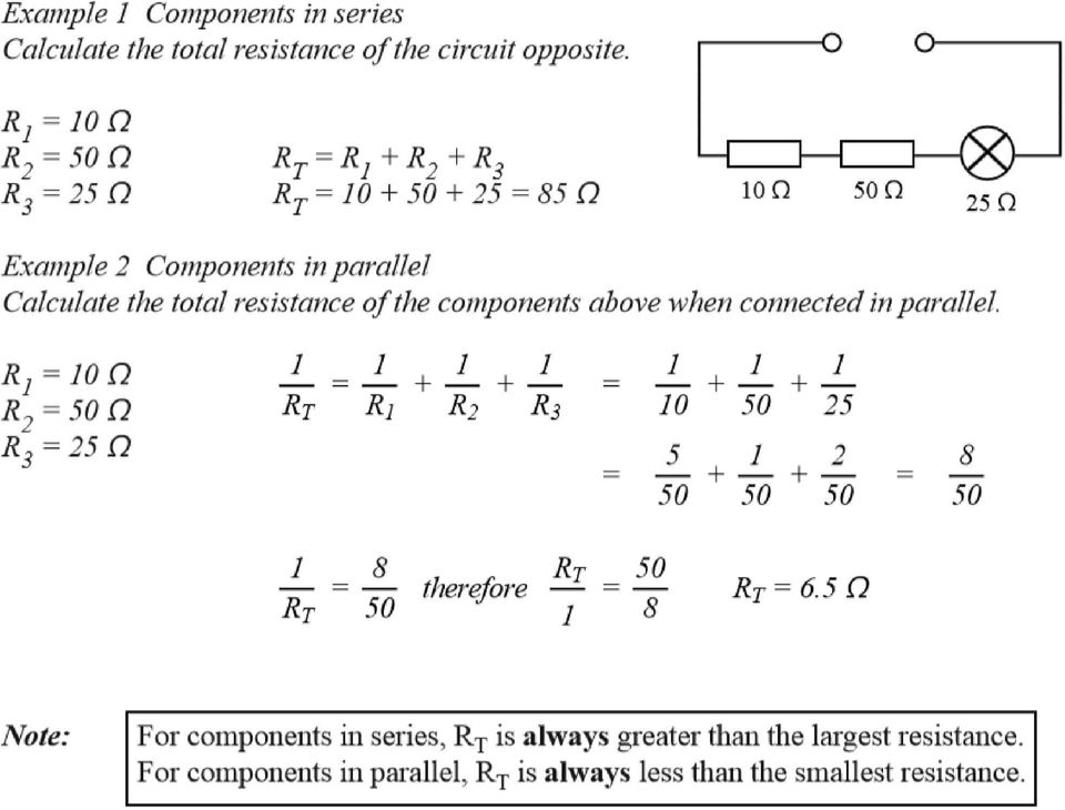
1 Series and Parallel Circuits Components in a circuit can be connected in series or parallel. A series arrangement of components is where they are inline with each other, i.e. connected end-to-end. A parallel arrangement of components is where they are connected across each other where the current has more than one path through that part of the circuit. Measuring Current and Potential Difference or oltage Electric current is measured using an ammeter which is connected in series with the component. Potential difference (p.d.), or voltage, is measured using a voltmeter which is connected in parallel with the component. Current and oltage (p.d.) Series Circuits The current is the same at all points in a series circuit. The sum of the potential differences across the components in a series circuit is equal to the voltage of the supply.
 Series Circuits The current is the same at all points in a series circuit.")
2 Current and voltage (p.d) Parallel Circuits The potential difference across components in parallel is the same for all components. The sum of the currents in parallel branches is equal to the current drawn from the supply. Resistors in Series When more than one component is connected in series, the total resistance of all the components is equivalent to one single resistor, R T, calculated using the relationship Resistors in Parallel When more than one component is connected in parallel, the total resistance of all the components is equivalent to one single resistor, R T, calculated using the relationship

3
4 Example mixed series and parallel circuit Calculate the total resistance of this circuit ) Work out which resistors are in series and which are in parallel Simplify one step at a time 2) Deal with series combination R 2 and R 3 first R T = R 2 + R 3 = = 2 Ω 3) Simplified version looks like this The combined resistance, R A of 2 Ω is in parallel with resistor R 4 This combination is in series with resistor R = which means 4) This is the same as R T = R + R comb = = 2 Ω A single resistance of 2 Ω is equivalent to the 4 resistor combination.
 This is the same as R T = R + R comb = 6 + 6 = 2 Ω A single resistance of 2 Ω is equivalent to the 4 resistor")
5 Advantages of parallel circuits If one component stops working the rest keep working Can have combinations of components switched on and off as desired All components connected in parallel will have the same voltage across them o Connecting components to the mains supply of 230 means that all components receive the full 230 Potential divider circuits A potential divider is a device or a circuit that uses two (or more) resistors in series, or a variable resistor (potentiometer) to o provide a fraction of the available voltage (p.d.) from the supply. The supply voltage is shared (divided up) between the components The larger resistance takes the larger share of the supply voltage in direct proportion o The ratio of resistances = the ratio of voltage shared between the resistors
 between the components The larger resistance takes the larger share of the supply voltage in direct proportion o The ratio of resistances = the ratio of")
6 Example 2 Consider the following voltage divider circuit: 20 kω 2 Y 0 kω X (a) Calculate the p.d. across X Y. R = 0 kω R 2 = 20 kω R R R 2 S S = 2 =? (b) Another 0 k resistor is added as shown. Calculate = 4 the new p.d. across X Y. 20 kω 2 0 kω Y 0 kω X R = 5 kω R 2 = 20 kω S = 2 =? R R R 2 S = 2.4

7 Electrical Energy and Power When there is current in a component, an energy change takes place. o e.g. when there is current in the filament in a lamp, the electrical energy is converted to heat and light. o In an electrical heating element, the energy change takes place in the resistance wire Electrical energy, like all types of energy is measured in Joules. Power is the rate of energy transfer (same definition as on page 4 for mechanical power) Energy (J) Power (W) time (s) The units of power are Watts (W). Watt means Joule of energy is transferred every second. Power, current and voltage The power (P) is also equal to the current (I) in Amps multiplied by the voltage () in volts. voltage () power (W) current (A) Example An electric heater operates on the mains voltage of 230. The heating elements operate at a current of 8 A. Calculate the power developed by the heater. = 230 I = 8 A P =? P = I = 8 x 230 = 840 W
 is also equal to the current (I) in Amps multiplied by the voltage () in volts.")
8 More Power equations The equations P = I and = IR can be combined by substitution to form two other equations. P = I 2 R P = I and substitute = IR into the equation for gives P = I IR = I 2 R P = 2 /R P = I and substitute I = into the equation for I gives P = x = This means there are three expressions for the power which are equivalent to each other Example An electric heater operates on the mains voltage of 230. The heater has a power rating of 2 0 kw. Calculate the resistance of the heating element of the heater. P = 2 kw P = R = = 230 R =?

9 Example 2 In the circuit shown opposite calculate: (a) the current in each resistor 40 (b) the p.d. across each resistor (c) the power dissipated in each resistor. 4 Ω 6 Ω 5 Ω 0 Ω (a) R S = R + R 2 = = 0 Ω R p R P = 5 Ω R T = = 0 Ω I 40 T T 4 A (current through 5 Ω) RT 0 The resistance of each parallel section is 0 so current through 6, 4 and 0 resistors all = 2 A (b) For the 5 Ω resistor: = IR = 4 5 = 20 for the 4 Ω resistor: = IR = 2 4 = 8 for the 6 Ω resistor: = IR = 2 6 = 2 for the 0 Ω resistor: = IR = 2 0 = 20 (c) For 5 Ω: P = I 2 R = = 80 W for 4 Ω: P = I 2 R = = 6 W for 6 Ω: P = I 2 R = = 24 W for 0 Ω: P = I 2 R = = 40 W
 For 5 Ω: P = I 2 R = 4 2 5 = 80 W for 4 Ω: P = I 2 R = 2 2 4 = 6 W for 6 Ω: P = I 2 R = 2 2 6 = 24 W for 0 Ω: P = I 2 R = 2 2 0")
13.10: How Series and Parallel Circuits Differ pg. 571
 13.10: How Series and Parallel Circuits Differ pg. 571 Key Concepts: 5. Connecting loads in series and parallel affects the current, potential difference, and total resistance. - Using your knowledge of
Student Exploration: Circuits
 Name: Date: Student Exploration: Circuits Vocabulary: ammeter, circuit, current, ohmmeter, Ohm s law, parallel circuit, resistance, resistor, series circuit, voltage Prior Knowledge Questions (Do these
Chapter 5. Parallel Circuits ISU EE. C.Y. Lee
 Chapter 5 Parallel Circuits Objectives Identify a parallel circuit Determine the voltage across each parallel branch Apply Kirchhoff s current law Determine total parallel resistance Apply Ohm s law in
Resistors in Series and Parallel Circuits
 69 Resistors in Series and Parallel Circuits E&M: Series and parallel circuits Equipment List DataStudio file: Not Required Qty s Part Numbers 1 C/DC Electronics Lab EM-8656 2 D cell 1.5 volt Introduction
Series and Parallel Circuits
 Direct Current (DC) Direct current (DC) is the unidirectional flow of electric charge. The term DC is used to refer to power systems that use refer to the constant (not changing with time), mean (average)
THE BREADBOARD; DC POWER SUPPLY; RESISTANCE OF METERS; NODE VOLTAGES AND EQUIVALENT RESISTANCE; THÉVENIN EQUIVALENT CIRCUIT
 THE BREADBOARD; DC POWER SUPPLY; RESISTANCE OF METERS; NODE VOLTAGES AND EQUIVALENT RESISTANCE; THÉVENIN EQUIVALENT CIRCUIT YOUR NAME LAB MEETING TIME Reference: C.W. Alexander and M.N.O Sadiku, Fundamentals
Chapter 13: Electric Circuits
 Chapter 13: Electric Circuits 1. A household circuit rated at 120 Volts is protected by a fuse rated at 15 amps. What is the maximum number of 100 watt light bulbs which can be lit simultaneously in parallel
Circuit symbol. Each of the cells has a potential difference of 1.5 volts. Figure 1. Use the correct answer from the box to complete the sentence.
 Q.(a) Draw one line from each circuit symbol to its correct name. Circuit symbol Name Diode Light-dependent resistor (LDR) Lamp Light-emitting diode (LED) (3) Figure shows three circuits. The resistors
People s Physics Book
 The Big Ideas: The name electric current is given to the phenomenon that occurs when an electric field moves down a wire at close to the speed of light. Voltage is the electrical energy density (energy
= (0.400 A) (4.80 V) = 1.92 W = (0.400 A) (7.20 V) = 2.88 W
 (4.80 V) = 1.92 W = (0.400 A) (7.20 V) = 2.88 W") Physics 2220 Module 06 Homework 0. What are the magnitude and direction of the current in the 8 Ω resister in the figure? Assume the current is moving clockwise. Then use Kirchhoff's second rule: 3.00
Physics 2220 Module 06 Homework 0. What are the magnitude and direction of the current in the 8 Ω resister in the figure? Assume the current is moving clockwise. Then use Kirchhoff's second rule: 3.00
Tutorial 12 Solutions
 PHYS000 Tutorial 2 solutions Tutorial 2 Solutions. Two resistors, of 00 Ω and 200 Ω, are connected in series to a 6.0 V DC power supply. (a) Draw a circuit diagram. 6 V 00 Ω 200 Ω (b) What is the total
Experiment NO.3 Series and parallel connection
 Experiment NO.3 Series and parallel connection Object To study the properties of series and parallel connection. Apparatus 1. DC circuit training system 2. Set of wires. 3. DC Power supply 4. Digital A.V.O.
Σ I in = Σ I out E = IR 1 + IR 2 FXA 2008 KIRCHHOFF S LAWS 1. Candidates should be able to : LAW 1 (K1)
") UNT G482 Module 3 2.3.1 Series & Parallel Circuits Candidates should be able to : KRCHHOFF S LAWS 1 LAW 1 (K1) State Kirchhoff s second law and appreciate that it is a consequence of conservation of energy.
UNT G482 Module 3 2.3.1 Series & Parallel Circuits Candidates should be able to : KRCHHOFF S LAWS 1 LAW 1 (K1) State Kirchhoff s second law and appreciate that it is a consequence of conservation of energy.
Preamble. Kirchoff Voltage Law (KVL) Series Resistors. In this section of my lectures we will be. resistor arrangements; series and
 Series Resistors. In this section of my lectures we will be. resistor arrangements; series and") Preamble Series and Parallel Circuits Physics, 8th Edition Custom Edition Cutnell & Johnson Chapter 0.6-0.8, 0.0 Pages 60-68, 69-6 n this section of my lectures we will be developing the two common types
Preamble Series and Parallel Circuits Physics, 8th Edition Custom Edition Cutnell & Johnson Chapter 0.6-0.8, 0.0 Pages 60-68, 69-6 n this section of my lectures we will be developing the two common types
7. What is the current in a circuit if 15 coulombs of electric charge move past a given point in 3 seconds? (1) 5 A (3) 18 A (2) 12 A (4) 45 A
 5 A (3) 18 A (2) 12 A (4) 45 A") 1. Compared to the number of free electrons in a conductor, the number of free electrons in an insulator of the same volume is less the same greater 2. Most metals are good electrical conductors because
1. Compared to the number of free electrons in a conductor, the number of free electrons in an insulator of the same volume is less the same greater 2. Most metals are good electrical conductors because
Parallel DC circuits
 Parallel DC circuits This worksheet and all related files are licensed under the Creative Commons Attribution License, version 1.0. To view a copy of this license, visit http://creativecommons.org/licenses/by/1.0/,
PHYSICS 111 LABORATORY Experiment #3 Current, Voltage and Resistance in Series and Parallel Circuits
 PHYSCS 111 LABORATORY Experiment #3 Current, Voltage and Resistance in Series and Parallel Circuits This experiment is designed to investigate the relationship between current and potential in simple series
Tristan s Guide to: Solving Series Circuits. Version: 1.0 Written in 2006. Written By: Tristan Miller [email protected]
 Tristan s Guide to: Solving Series Circuits. Version: 1.0 Written in 2006 Written By: Tristan Miller [email protected] Series Circuits. A Series circuit, in my opinion, is the simplest circuit
Light Bulbs in Parallel Circuits
 Light Bulbs in Parallel Circuits In the last activity, we analyzed several different series circuits. In a series circuit, there is only one complete pathway for the charge to travel. Here are the basic
Transformer circuit calculations
 Transformer circuit calculations This worksheet and all related files are licensed under the Creative Commons Attribution License, version 1.0. To view a copy of this license, visit http://creativecommons.org/licenses/by/1.0/,
Resistors in Series and Parallel
 Resistors in Series and Parallel Bởi: OpenStaxCollege Most circuits have more than one component, called a resistor that limits the flow of charge in the circuit. A measure of this limit on charge flow
Series and Parallel Resistive Circuits Physics Lab VIII
 Series and Parallel Resistive Circuits Physics Lab VIII Objective In the set of experiments, the theoretical expressions used to calculate the total resistance in a combination of resistors will be tested
AP1 Electricity. 1. A student wearing shoes stands on a tile floor. The students shoes do not fall into the tile floor due to
 1. A student wearing shoes stands on a tile floor. The students shoes do not fall into the tile floor due to (A) a force of repulsion between the shoes and the floor due to macroscopic gravitational forces.
Objectives 200 CHAPTER 4 RESISTANCE
 Objectives Explain the differences among conductors, insulators, and semiconductors. Define electrical resistance. Solve problems using resistance, voltage, and current. Describe a material that obeys
Equipment: Power Supply, DAI, Variable resistance (8311), Variable inductance (8321)
, Variable inductance (8321)") Lab 4: 3-phase circuits. Objective: to study voltage-current relationships in 3-phase circuits; to learn to make delta and Y connections; to calculate and measure real, apparent, and reactive powers. Equipment:
Lab 4: 3-phase circuits. Objective: to study voltage-current relationships in 3-phase circuits; to learn to make delta and Y connections; to calculate and measure real, apparent, and reactive powers. Equipment:
Chapter 19. Electric Circuits
 Chapter 9 Electric Circuits Series Wiring There are many circuits in which more than one device is connected to a voltage source. Series wiring means that the devices are connected in such a way that there
CHAPTER 28 ELECTRIC CIRCUITS
 CHAPTER 8 ELECTRIC CIRCUITS 1. Sketch a circuit diagram for a circuit that includes a resistor R 1 connected to the positive terminal of a battery, a pair of parallel resistors R and R connected to the
Ohm s Law. George Simon Ohm
 Ohm s Law George Simon Ohm The law which governs most simple and many complex electrical phenomena is known as Ohm s Law. It is the most important law in electricity. In 1827, a German locksmith and mathematician
V out. Figure 1: A voltage divider on the left, and potentiometer on the right.
 Living with the Lab Fall 202 Voltage Dividers and Potentiometers Gerald Recktenwald v: November 26, 202 [email protected] Introduction Voltage dividers and potentiometers are passive circuit components
Experiment 4: Sensor Bridge Circuits (tbc 1/11/2007, revised 2/20/2007, 2/28/2007) I. Introduction. From Voltage Dividers to Wheatstone Bridges
 I. Introduction. From Voltage Dividers to Wheatstone Bridges") Experiment 4: Sensor Bridge Circuits (tbc //2007, revised 2/20/2007, 2/28/2007) Objective: To implement Wheatstone bridge circuits for temperature measurements using thermistors. I. Introduction. From
Experiment 4: Sensor Bridge Circuits (tbc //2007, revised 2/20/2007, 2/28/2007) Objective: To implement Wheatstone bridge circuits for temperature measurements using thermistors. I. Introduction. From
OHM S LAW AND RESISTANCE
 OHM S LAW AND RESISTANCE Resistance is one of the basic principles of Ohm s law, and can be found in virtually any device used to conduct electricity. Georg Simon Ohm was a German physicist who conducted
Physics 133: tutorial week 4 Ohm s law, electrical power, emf and internal resistance.
 Physics 133: tutorial week 4 Ohm s law, electrical power, emf and internal resistance. 41. The heating element of a clothes drier has a resistance of 11Ïand is connected across a 240V electrical outlet.
Physics, Chapter 27: Direct-Current Circuits
 University of Nebraska - Lincoln DigitalCommons@University of Nebraska - Lincoln Robert Katz Publications Research Papers in Physics and Astronomy 1-1-1958 Physics, Chapter 27: Direct-Current Circuits
Method 1: 30x50 30 50 18.75 15 18.75 0.8. 80 Method 2: 15
 The University of New South Wales School of Electrical Engineering and Telecommunications ELEC Electrical and Telecommunications Engineering Tutorial Solutions Q. In the figure below a voltage source and
V out = V in x R 2 (R 1 + R 2 ) V o = V i R 1 FXA 2008 POTENTIAL DIVIDER CIRCUIT 1. Candidates should be able to : SUPPLYING A FIXED PD
 V o = V i R 1 FXA 2008 POTENTIAL DIVIDER CIRCUIT 1. Candidates should be able to : SUPPLYING A FIXED PD") POTENTIAL DIIDER CIRCUIT 1 Candidates should be able to : SUPPLYING A FIXED PD Draw a simple potential divider circuit. Explain how a potential divider circuit can be used to produce a variable pd. The
POTENTIAL DIIDER CIRCUIT 1 Candidates should be able to : SUPPLYING A FIXED PD Draw a simple potential divider circuit. Explain how a potential divider circuit can be used to produce a variable pd. The
Lab 3 - DC Circuits and Ohm s Law
 Lab 3 DC Circuits and Ohm s Law L3-1 Name Date Partners Lab 3 - DC Circuits and Ohm s Law OBJECTIES To learn to apply the concept of potential difference (voltage) to explain the action of a battery in
Electronics. Basic Concepts. Yrd. Doç. Dr. Aytaç GÖREN Yrd. Doç. Dr. Levent ÇETİN
 Electronics Basic Concepts Electric charge Ordinary matter is made up of atoms which have positively charged nuclei and negatively charged electrons surrounding them. Charge is quantized as the subtraction
Chapter 7 Direct-Current Circuits
 Chapter 7 Direct-Current Circuits 7. Introduction...7-7. Electromotive Force...7-3 7.3 Resistors in Series and in Parallel...7-5 7.4 Kirchhoff s Circuit Rules...7-7 7.5 Voltage-Current Measurements...7-9
Experiment 6 ~ Joule Heating of a Resistor
 Experiment 6 ~ Joule Heating of a Resistor Introduction: The power P absorbed in an electrical resistor of resistance R, current I, and voltage V is given by P = I 2 R = V 2 /R = VI. Despite the fact that
Current, Resistance and Electromotive Force. Young and Freedman Chapter 25
 Current, Resistance and Electromotive Force Young and Freedman Chapter 25 Electric Current: Analogy, water flowing in a pipe H 2 0 gallons/minute Flow Rate is the NET amount of water passing through a
Electrical Fundamentals Module 3: Parallel Circuits
 Electrical Fundamentals Module 3: Parallel Circuits PREPARED BY IAT Curriculum Unit August 2008 Institute of Applied Technology, 2008 ATE310- Electrical Fundamentals 2 Module 3 Parallel Circuits Module
Parallel and Series Resistors, Kirchoff s Law
 Experiment 2 31 Kuwait University Physics 107 Physics Department Parallel and Series Resistors, Kirchoff s Law Introduction In this experiment the relations among voltages, currents and resistances for
Analysis of a single-loop circuit using the KVL method
 Analysis of a single-loop circuit using the KVL method Figure 1 is our circuit to analyze. We shall attempt to determine the current through each element, the voltage across each element, and the power
FB-DC3 Electric Circuits: Series and Parallel Circuits
 CREST Foundation Electrical Engineering: DC Electric Circuits Kuphaldt FB-DC3 Electric Circuits: Series and Parallel Circuits Contents 1. What are "series" and "parallel"? 2. Simple series circuits 3.
Resistance, Ohm s Law, and the Temperature of a Light Bulb Filament
 Resistance, Ohm s Law, and the Temperature of a Light Bulb Filament Name Partner Date Introduction Carbon resistors are the kind typically used in wiring circuits. They are made from a small cylinder of
Electrical Circuit Theory
 Electrical Circuit Theory Learning Objectives: 1. Review the basic electrical concepts of voltage, amperage, and resistance. 2. Review the components of a basic automotive electrical circuit. 3. Introduce
TECH TIP # 37 SOLVING SERIES/PARALLEL CIRCUITS THREE LAWS --- SERIES CIRCUITS LAW # 1 --- THE SAME CURRENT FLOWS THROUGH ALL PARTS OF THE CIRCUIT
 TECH TIP # 37 SOLVING SERIES/PARALLEL CIRCUITS Please study this Tech Tip along with assignment 4 in Basic Electricity. Parallel circuits differ from series circuits in that the current divides into a
Experiment 4 ~ Resistors in Series & Parallel
 Experiment 4 ~ Resistors in Series & Parallel Objective: In this experiment you will set up three circuits: one with resistors in series, one with resistors in parallel, and one with some of each. You
Circuits. The light bulbs in the circuits below are identical. Which configuration produces more light? (a) circuit I (b) circuit II (c) both the same
 circuit I (b) circuit II (c) both the same") Circuits The light bulbs in the circuits below are identical. Which configuration produces more light? (a) circuit I (b) circuit II (c) both the same Circuit II has ½ current of each branch of circuit
Circuits The light bulbs in the circuits below are identical. Which configuration produces more light? (a) circuit I (b) circuit II (c) both the same Circuit II has ½ current of each branch of circuit
ELECTRICAL CIRCUITS. Electrical Circuits
 Electrical Circuits A complete path, or circuit, is needed before voltage can cause a current flow through resistances to perform work. There are several types of circuits, but all require the same basic
Joule Equivalent of Electrical Energy
 by Dr. James E. Parks Department of Physics and Astronomy 401 Nielsen Physics Building The University of Tennessee Knoxville, Tennessee 37996-1200 Copyright October, 2013 by James Edgar Parks* *All rights
Resistors in Series and Parallel
 OpenStax-CNX module: m42356 1 Resistors in Series and Parallel OpenStax College This work is produced by OpenStax-CNX and licensed under the Creative Commons Attribution License 3.0 Abstract Draw a circuit
101 BASICS SERIES LEARNING MODULE 2: FUNDAMENTALS OF ELECTRICITY. Cutler-Hammer
 101 BASICS SERIES LEARNING MODULE 2: FUNDAMENTALS OF ELECTRICITY Cutler-Hammer WELCOME Welcome to Module 2, Fundamentals of Electricity. This module will cover the fundamentals of electricity in a practical
LAB2 Resistors, Simple Resistive Circuits in Series and Parallel Objective:
 LAB2 Resistors, Simple Resistive Circuits in Series and Parallel Objective: In this lab, you will become familiar with resistors and potentiometers and will learn how to measure resistance. You will also
Three-phase AC circuits
 Three-phase AC circuits This worksheet and all related files are licensed under the Creative Commons Attribution License, version 1.0. To view a copy of this license, visit http://creativecommons.org/licenses/by/1.0/,
Experiment 8 Series-Parallel Circuits
 Experiment 8 Series-Parallel Circuits EL 111 - DC Fundamentals By: Walter Banzhaf, E.K. Smith, and Winfield Young University of Hartford Ward College of Technology Objectives: 1. For the student to measure
CURRENT ELECTRICITY INTRODUCTION TO RESISTANCE, CAPACITANCE AND INDUCTANCE
 CURRENT ELECTRICITY INTRODUCTION TO RESI STANCE, CAPACITANCE AND INDUCTANCE P R E A M B L E This problem is adapted from an on-line knowledge enhancement module for a PGCE programme. It is used to cover
Resistors. Some substances are insulators. A battery will not make detectible current flow through them.
 Resistors Some substances are insulators. A battery will not make detectible current flow through them. Many substances (lead, iron, graphite, etc.) will let current flow. For most substances that are
Solutions to Bulb questions
 Solutions to Bulb questions Note: We did some basic circuits with bulbs in fact three main ones I can think of I have summarized our results below. For the final exam, you must have an understanding of
Fig. 1 Analogue Multimeter Fig.2 Digital Multimeter
 ELECTRICAL INSTRUMENT AND MEASUREMENT Electrical measuring instruments are devices used to measure electrical quantities such as electric current, voltage, resistance, electrical power and energy. MULTIMETERS
Example: Determine the power supplied by each of the sources, independent and dependent, in this circuit:
 Example: Determine the power supplied by each of the sources, independent and dependent, in this circuit: Solution: We ll begin by choosing the bottom node to be the reference node. Next we ll label the
Ohm's Law and Circuits
 2. Conductance, Insulators and Resistance A. A conductor in electricity is a material that allows electrons to flow through it easily. Metals, in general, are good conductors. Why? The property of conductance
Lecture Notes: ECS 203 Basic Electrical Engineering Semester 1/2010. Dr.Prapun Suksompong 1 June 16, 2010
 Sirindhorn International Institute of Technology Thammasat University School of Information, Computer and Communication Technology Lecture Notes: ECS 203 Basic Electrical Engineering Semester 1/2010 Dr.Prapun
Cornerstone Electronics Technology and Robotics I Week 15 Combination Circuits (Series-Parallel Circuits)
") Cornerstone Electronics Technology and Robotics I Week 15 Combination Circuits (Series-Parallel Circuits) Administration: o Prayer o Turn in quiz Electricity and Electronics, Chapter 8, Introduction: o
Cornerstone Electronics Technology and Robotics I Week 15 Combination Circuits (Series-Parallel Circuits) Administration: o Prayer o Turn in quiz Electricity and Electronics, Chapter 8, Introduction: o
COMPOUND CIRCUITS. Voltage (volts) Across Bulb B. Across the Battery. Across Bulb A. Current (amperes) Between A & B. Between Battery & B
 Across Bulb B. Across the Battery. Across Bulb A. Current (amperes) Between A & B. Between Battery & B") OMPOUN IUITS LOGGING ON Go to www.explorelearning.com and log in using your Username and Password. Select rowse Gizmos icon at the upper left. Select Grades 9 2 Physics Select Electricity and Magnetism
OMPOUN IUITS LOGGING ON Go to www.explorelearning.com and log in using your Username and Password. Select rowse Gizmos icon at the upper left. Select Grades 9 2 Physics Select Electricity and Magnetism
PROCEDURE: 1. Measure and record the actual values of the four resistors listed in Table 10-1.
 The answer to two questions will help you identify a series or parallel connection: (1) Will the identical current go through both components? f the answer is yes, the components are in series. (2) Are
Tristan s Guide to: Solving Parallel Circuits. Version: 1.0 Written in 2006. Written By: Tristan Miller [email protected]
 Tristan s Guide to: Solving Parallel Circuits. Version: 1.0 Written in 2006 Written By: Tristan Miller [email protected] Parallel Circuits. Parallel Circuits are a little bit more complicated
Lesson Plan. Parallel Resistive Circuits Part 1 Electronics
 Parallel Resistive Circuits Part 1 Electronics Lesson Plan Performance Objective At the end of the lesson, students will demonstrate the ability to apply problem solving and analytical techniques to calculate
After completing this chapter, the student should be able to:
 DC Circuits OBJECTIVES After completing this chapter, the student should be able to: Solve for all unknown values (current, voltage, resistance, and power) in a series, parallel, or series-parallel circuit.
Apprentice Telecommunications Technician Test (CTT) Study Guide
 Study Guide") Apprentice Telecommunications Technician Test (CTT) Study Guide 1 05/2014 Study Guide for Pacific Gas & Electric Company Apprentice Telecommunications Technician Qualifying Test (CTT) About the Test The
Apprentice Telecommunications Technician Test (CTT) Study Guide 1 05/2014 Study Guide for Pacific Gas & Electric Company Apprentice Telecommunications Technician Qualifying Test (CTT) About the Test The
AP Physics Electricity and Magnetism #4 Electrical Circuits, Kirchoff s Rules
 Name Period AP Physics Electricity and Magnetism #4 Electrical Circuits, Kirchoff s Rules Dr. Campbell 1. Four 240 Ω light bulbs are connected in series. What is the total resistance of the circuit? What
Introduction to Electricity & Magnetism. Dr Lisa Jardine-Wright Cavendish Laboratory
 Introduction to Electricity & Magnetism Dr Lisa Jardine-Wright Cavendish Laboratory Examples of uses of electricity Christmas lights Cars Electronic devices Human body Electricity? Electricity is the presence
CLASS TEST GRADE 11. PHYSICAL SCIENCES: PHYSICS Test 3: Electricity and magnetism
 CLASS TEST GRADE 11 PHYSICAL SCIENCES: PHYSICS Test 3: Electricity and magnetism MARKS: 45 TIME: 1 hour INSTRUCTIONS AND INFORMATION 1. Answer ALL the questions. 2. You may use non-programmable calculators.
How To Wire A Three Phase, Single Phase, Wye Transformer
 Three-Phase Transformers When more power is needed - three transformers can be tied together. This is called three-phase. Here s a simple way of comparing single-phase to threephase power. Single-Phase
Series and Parallel Resistive Circuits
 Series and Parallel Resistive Circuits The configuration of circuit elements clearly affects the behaviour of a circuit. Resistors connected in series or in parallel are very common in a circuit and act
Eðlisfræði 2, vor 2007
 [ Assignment View ] [ Print ] Eðlisfræði 2, vor 2007 30. Inductance Assignment is due at 2:00am on Wednesday, March 14, 2007 Credit for problems submitted late will decrease to 0% after the deadline has
PS-6.2 Explain the factors that determine potential and kinetic energy and the transformation of one to the other.
 PS-6.1 Explain how the law of conservation of energy applies to the transformation of various forms of energy (including mechanical energy, electrical energy, chemical energy, light energy, sound energy,
Energy, Work, and Power
 Energy, Work, and Power This worksheet and all related files are licensed under the Creative Commons Attribution License, version 1.0. To view a copy of this license, visit http://creativecommons.org/licenses/by/1.0/,
Chapter 11. Inductors ISU EE. C.Y. Lee
 Chapter 11 Inductors Objectives Describe the basic structure and characteristics of an inductor Discuss various types of inductors Analyze series inductors Analyze parallel inductors Analyze inductive
EDEXCEL NATIONAL CERTIFICATE/DIPLOMA UNIT 67 - FURTHER ELECTRICAL PRINCIPLES NQF LEVEL 3 OUTCOME 1 TUTORIAL 1 - DIRECT CURRENT CIRCUIT THEOREMS
 EDEXCE NATIONA CERTIFICATE/DIPOMA UNIT 67 - FURTHER EECTRICA PRINCIPES NQF EVE 3 OUTCOME 1 TUTORIA 1 - DIRECT CURRENT CIRCUIT THEOREMS Unit content 1 Be able to apply direct current (DC) circuit analysis
LM 358 Op Amp. If you have small signals and need a more useful reading we could amplify it using the op amp, this is commonly used in sensors.
 LM 358 Op Amp S k i l l L e v e l : I n t e r m e d i a t e OVERVIEW The LM 358 is a duel single supply operational amplifier. As it is a single supply it eliminates the need for a duel power supply, thus
Basic Laws Circuit Theorems Methods of Network Analysis Non-Linear Devices and Simulation Models
 EE Modul 1: Electric Circuits Theory Basic Laws Circuit Theorems Methods of Network Analysis Non-Linear Devices and Simulation Models EE Modul 1: Electric Circuits Theory Current, Voltage, Impedance Ohm
Experiment #3, Ohm s Law
 Experiment #3, Ohm s Law 1 Purpose Physics 182 - Summer 2013 - Experiment #3 1 To investigate the -oltage, -, characteristics of a carbon resistor at room temperature and at liquid nitrogen temperature,
Unit: Charge Differentiated Task Light it Up!
 The following instructional plan is part of a GaDOE collection of Unit Frameworks, Performance Tasks, examples of Student Work, and Teacher Commentary. Many more GaDOE approved instructional plans are
Experiment #5, Series and Parallel Circuits, Kirchhoff s Laws
 Physics 182 Summer 2013 Experiment #5 1 Experiment #5, Series and Parallel Circuits, Kirchhoff s Laws 1 Purpose Our purpose is to explore and validate Kirchhoff s laws as a way to better understanding
Which Bulb Burns Brighter? One is a 60-watt bulb and the other a 100-watt bulb, and they are connected in an electric circuit.
 Which Bulb Burns Brighter? One is a 60-watt bulb and the other a 100-watt bulb, and they are connected in an electric circuit. Look at the text on page 541 for the answer. CHPTE 23 Series and Parallel
Module 2. DC Circuit. Version 2 EE IIT, Kharagpur
 Module DC Circuit Lesson 4 Loop Analysis of resistive circuit in the context of dc voltages and currents Objectives Meaning of circuit analysis; distinguish between the terms mesh and loop. To provide
Power Factor Correction for Power Systems First Semester Report Spring Semester 2007
 Power Factor Correction for Power Systems First Semester Report Spring Semester 2007 by Pamela Ackerman Prepared to partially fulfill the requirements for EE401 Department of Electrical and Computer Engineering
Current and Voltage Measurements. Current measurement
 Current and oltage easurements Current measurement ccording to current continuity (i.e. charge conservation) law, the current can be measured in any portion of a single loop circuit. B Circuit Element
Electrical Resistance Resistance (R)
") Electrical Resistance Resistance (R) Any device in a circuit which converts electrical energy into some other form impedes the current. The device which converts electrical energy to heat energy is termed
Electrical Resistance Resistance (R) Any device in a circuit which converts electrical energy into some other form impedes the current. The device which converts electrical energy to heat energy is termed
Q1. The graph below shows how a sinusoidal alternating voltage varies with time when connected across a resistor, R.
 Q1. The graph below shows how a sinusoidal alternating voltage varies with time when connected across a resistor, R. (a) (i) State the peak-to-peak voltage. peak-to-peak voltage...v (1) (ii) State the
CURRENT ELECTRICITY - I
 CURRNT LCTRCTY - 1. lectric Current 2. Conventional Current 3. Drift elocity of electrons and current 4. Current Density 5. Ohm s Law 6. Resistance, Resistivity, Conductance & Conductivity 7. Temperature
3.- What atom s particle moves through a conductor material? 4.- Which are the electric components of an elemental electric circuit?
 1.- What is electricity? 2.- Write down the name of the atom s particles. 3.- What atom s particle moves through a conductor material? 4.- Which are the electric components of an elemental electric circuit?
Section B: Electricity
 Section B: Electricity We use mains electricity, supplied by power stations, for all kinds of appliances in our homes, so it is very important to know how to use it safely. In this chapter you will learn
Voltage Drop (Single-Phase)
") Voltage Drop (Single-Phase) To Find: To Find Voltage Drop Formula: 2 x K x L x I V.D. = ------------------- C.M. Variables: C.M. = Circular Mill Area (Chapter 9, Table 8) To Find Voltage Drop Percentage
Voltage Drop (Single-Phase) To Find: To Find Voltage Drop Formula: 2 x K x L x I V.D. = ------------------- C.M. Variables: C.M. = Circular Mill Area (Chapter 9, Table 8) To Find Voltage Drop Percentage
Current Electricity Lab Series/Parallel Circuits. Safety and Equipment Precautions!
 Current Electricity Lab Series/Parallel Circuits Name Safety and Equipment Precautions! Plug in your power supply and use ONLY the D.C. terminals of the power source, NOT the A. C. terminals. DO NOT touch
NAME: DATE: (Please Print) RESISTOR NETWORK AND OHMS LAW PRACTICE EXAM (See formulas at the back of this exam) 120 Volts AC 35 Ohms
 RESISTOR NETWORK AND OHMS LAW PRACTICE EXAM (See formulas at the back of this exam) 120 Volts AC 35 Ohms") NAM: DAT: (lease rint) RSISTOR NTWORK AND OHMS LAW RACTIC XAM (See formulas at the back of this exam) 25 Ohms 120 Volts AC 35 Ohms 1. Based on the drawing above, what is the total circuit resistance? This
NAM: DAT: (lease rint) RSISTOR NTWORK AND OHMS LAW RACTIC XAM (See formulas at the back of this exam) 25 Ohms 120 Volts AC 35 Ohms 1. Based on the drawing above, what is the total circuit resistance? This
Electric Potential Difference
 Name: Electric Potential Difference Read from Lesson 1 of the Current Electricity chapter at The Physics Classroom: http://www.physicsclassroom.com/class/circuits/u9l1a.html http://www.physicsclassroom.com/class/circuits/u9l1b.html
Chapter 1. Fundamental Electrical Concepts
 Chapter 1 Fundamental Electrical Concepts Charge, current, voltage, power circuits, nodes, branches Branch and node voltages, Kirchhoff Laws Basic circuit elements, combinations 01 fundamental 1 1.3 Electrical
Series and Parallel Circuits
 Series and Parallel Circuits Direct-Current Series Circuits A series circuit is a circuit in which the components are connected in a line, one after the other, like railroad cars on a single track. There