Electronics. Basic Concepts. Yrd. Doç. Dr. Aytaç GÖREN Yrd. Doç. Dr. Levent ÇETİN
|
|
|
- Kathlyn Floyd
- 8 years ago
- Views:
Transcription
1 Electronics Basic Concepts

2 Electric charge Ordinary matter is made up of atoms which have positively charged nuclei and negatively charged electrons surrounding them. Charge is quantized as the subtraction of number of protons from number of electrons. (Unit: Coulombs)

3 Electric charge The influence of charges is characterized in terms of the forces between them (Coulomb's law) and the electric field and voltage produced by them. F e k e k e q 1 d q 2 2 N 1 9 Nm C 2


4 Electric Current The rate of flow of electric charge is called electric current (I) and is measured in Coulombs/second which is named Amperes. Since electric charge is quantized in discrete multiples of the electron charge, it is instructive to look at electric current as the movement of multiple microscopic charge carriers in a conductor


5 Direction of Electric Current The conventional current direction is the direction from high voltage to low voltage, high energy to low energy, and thus has some appeal in its parallel to the flow of water from high pressure to low The flow of electrons around the circuit is opposite to the direction of the conventional current flow. This is because the charge on an electron is negative by definition and so is attracted to the positive terminal.

6 Ammeter An ammeter is an instrument for measuring the electric current in amperes in a branch of an electric circuit. It must be placed in series with the measured branch, and must have very low resistance to avoid significant alteration of the current it is to measure.


7 Electrical Potential Difference or Voltage Voltage, ( V ) is the potential energy of an electrical supply stored in the form of an electrical charge. Voltage can be thought of as the force that pushes electrons through a conductor and the greater the voltage the greater is its ability to "push" the electrons through a given circuit.


8 Voltmeter A voltmeter measures the change in voltage between two points in an electric circuit and therefore must be connected in parallel with the portion of the circuit on which the measurement is made.

9 Electric Circuit Most practical applications of electricity involve the flow of electric current in a closed path under the influence of a driving voltage, analogous to the flow in a water circuit under the influence of a driving pressure. A complete path, typically through conductors such as wires and through circuit elements, is called an electric circuit.


10 Resistance The Resistance, ( R ) of a circuit or an element of the circuit is its ability to resist or prevent the flow of current (electron flow) through itself making it necessary to apply a greater voltage to the electrical circuit to cause the current to flow again. Resistance is measured in Ohms, Greek symbol ( Ω, Omega ) with prefixes used to denote Kilo-ohms (kω = 10 3 Ω) and Mega-ohms (MΩ = 10 6 Ω). Resistance cannot be negative only positive.
 with prefixes used to denote Kilo-ohms (kω = 10 3 Ω)")
 is a")
11 Resistivity The resistance of a given sample will increase with the length, but decrease with greater cross-sectional area. Resistance is measured in ohms. Length over area has units of 1/distance. To end up with ohms, resistivity must be in the units of "ohms distance" R L m Ωm A m 2 Electrical resistivity (also known as resistivity, specific electrical resistance, or volume resistivity) is a measure of how strongly a material opposes the flow of electric current.
 is a measure of how strongly a material")

12 Relationship between Voltage and Current Relationship between Voltage and Current in a circuit of constant resistance: Quantity Symbol Unit of Measure Abbreviati on Voltage V or E Volt V Current I Amp A Resistance R Ohms Ω


13 Ohmmeter The standard way to measure resistance in ohms is to supply a constant voltage to the resistance and measure the current through it. That current is of course inversely proportional to the resistance. Multimeter video

, the movement of electric charge periodically reverses direction.")
14 Alternating or Direct The source of an electric circuit may be an Alternating or Direct current or voltage supply. In alternating current (AC, also ac), the movement of electric charge periodically reverses direction. In direct current (DC, also dc), the flow of electric charge is only in one direction.

15 Alternating Current or Voltage AC is the form in which electric power is delivered to businesses and residences. The usual waveform of an AC power circuit is a sine wave.


16 The AC Waveform
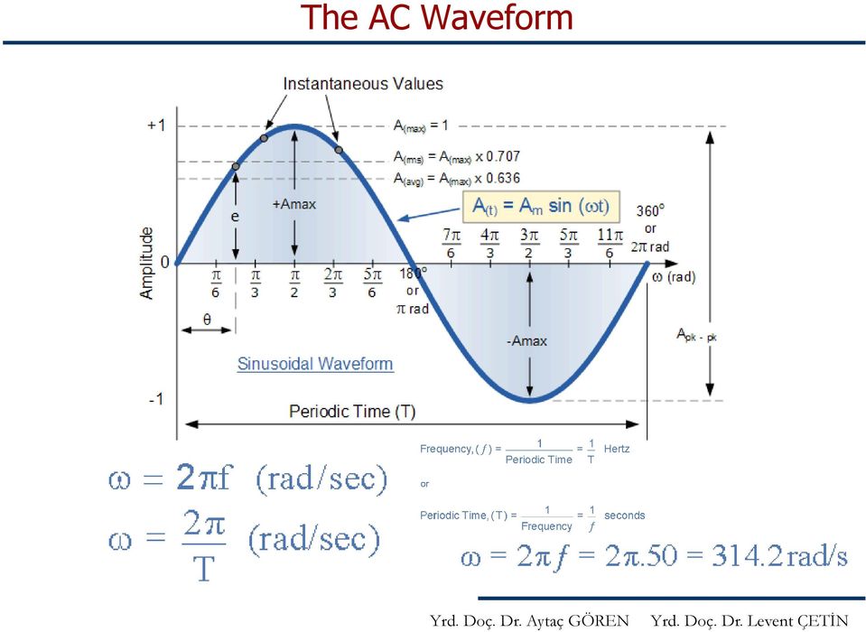

17 The AC Waveform There are 3 ways to quantify the magnitude of a sine wave. Peak voltage determines how far the voltage swings, either positive or negative, from the point of reference. Peak-Peak Voltage represents how far the voltage swings, from positive to negative max values. The RMS Voltage represents the effective voltage in an AC system. The RMS values of AC voltages are the DC equivalent values that provide the same power to the load. For sinusoidal network voltage: V V max RMS. 707 V max 2 0


18 Measurement of AC Waveform An instrument called an oscilloscope is used to display a changing voltage over time on a graphical screen. Oscilloscope video

19 Osciloscope

20 Osciloscope

21 Resistance in AC Circuits The circuits elements, under the effect of AC sources, demonstrate a complex oppositon effect against the electron flow. This oppositon is called impedance. The impedance is used to describe voltage current relationship in AC circuits.
22 Power in Electric Circuits The electric power in watts associated with a complete electric circuit or a circuit component represents the rate at which energy is converted from the electrical energy of the moving charges to some other form, e.g., heat, mechanical energy, or energy stored in electric fields or magnetic fields. In a DC Circuit the power is given by the product of applied voltage and the electric current: P = VI [Watt]
23 Power in Electric Circuits As in DC circuits, the instantaneous electric power in an AC circuit is given by P=VI where V and I are the instantaneous voltage and current.
24
25 References - Hyperphysics website. -
Fig. 1 Analogue Multimeter Fig.2 Digital Multimeter
 ELECTRICAL INSTRUMENT AND MEASUREMENT Electrical measuring instruments are devices used to measure electrical quantities such as electric current, voltage, resistance, electrical power and energy. MULTIMETERS
13.10: How Series and Parallel Circuits Differ pg. 571
 13.10: How Series and Parallel Circuits Differ pg. 571 Key Concepts: 5. Connecting loads in series and parallel affects the current, potential difference, and total resistance. - Using your knowledge of
Series and Parallel Circuits
 Series and Parallel Circuits Components in a circuit can be connected in series or parallel. A series arrangement of components is where they are inline with each other, i.e. connected end-to-end. A parallel
101 BASICS SERIES LEARNING MODULE 2: FUNDAMENTALS OF ELECTRICITY. Cutler-Hammer
 101 BASICS SERIES LEARNING MODULE 2: FUNDAMENTALS OF ELECTRICITY Cutler-Hammer WELCOME Welcome to Module 2, Fundamentals of Electricity. This module will cover the fundamentals of electricity in a practical
Aircraft Electrical System
 Chapter 9 Aircraft Electrical System Introduction The satisfactory performance of any modern aircraft depends to a very great degree on the continuing reliability of electrical systems and subsystems.
Introduction to Electricity & Magnetism. Dr Lisa Jardine-Wright Cavendish Laboratory
 Introduction to Electricity & Magnetism Dr Lisa Jardine-Wright Cavendish Laboratory Examples of uses of electricity Christmas lights Cars Electronic devices Human body Electricity? Electricity is the presence
PS-6.2 Explain the factors that determine potential and kinetic energy and the transformation of one to the other.
 PS-6.1 Explain how the law of conservation of energy applies to the transformation of various forms of energy (including mechanical energy, electrical energy, chemical energy, light energy, sound energy,
Lecture Notes: ECS 203 Basic Electrical Engineering Semester 1/2010. Dr.Prapun Suksompong 1 June 16, 2010
 Sirindhorn International Institute of Technology Thammasat University School of Information, Computer and Communication Technology Lecture Notes: ECS 203 Basic Electrical Engineering Semester 1/2010 Dr.Prapun
STUDY GUIDE: ELECTRICITY AND MAGNETISM
 319 S. Naperville Road Wheaton, IL 60187 www.questionsgalore.net Phone: (630) 580-5735 E-Mail: info@questionsgalore.net Fax: (630) 580-5765 STUDY GUIDE: ELECTRICITY AND MAGNETISM An atom is made of three
David L. Senasack June, 2006 Dale Jackson Career Center, Lewisville Texas. The PN Junction
 David L. Senasack June, 2006 Dale Jackson Career Center, Lewisville Texas The PN Junction Objectives: Upon the completion of this unit, the student will be able to; name the two categories of integrated
Experiment NO.3 Series and parallel connection
 Experiment NO.3 Series and parallel connection Object To study the properties of series and parallel connection. Apparatus 1. DC circuit training system 2. Set of wires. 3. DC Power supply 4. Digital A.V.O.
Chapter 13: Electric Circuits
 Chapter 13: Electric Circuits 1. A household circuit rated at 120 Volts is protected by a fuse rated at 15 amps. What is the maximum number of 100 watt light bulbs which can be lit simultaneously in parallel
3.- What atom s particle moves through a conductor material? 4.- Which are the electric components of an elemental electric circuit?
 1.- What is electricity? 2.- Write down the name of the atom s particles. 3.- What atom s particle moves through a conductor material? 4.- Which are the electric components of an elemental electric circuit?
Series and Parallel Circuits
 Direct Current (DC) Direct current (DC) is the unidirectional flow of electric charge. The term DC is used to refer to power systems that use refer to the constant (not changing with time), mean (average)
Basic Laws Circuit Theorems Methods of Network Analysis Non-Linear Devices and Simulation Models
 EE Modul 1: Electric Circuits Theory Basic Laws Circuit Theorems Methods of Network Analysis Non-Linear Devices and Simulation Models EE Modul 1: Electric Circuits Theory Current, Voltage, Impedance Ohm
THE BREADBOARD; DC POWER SUPPLY; RESISTANCE OF METERS; NODE VOLTAGES AND EQUIVALENT RESISTANCE; THÉVENIN EQUIVALENT CIRCUIT
 THE BREADBOARD; DC POWER SUPPLY; RESISTANCE OF METERS; NODE VOLTAGES AND EQUIVALENT RESISTANCE; THÉVENIN EQUIVALENT CIRCUIT YOUR NAME LAB MEETING TIME Reference: C.W. Alexander and M.N.O Sadiku, Fundamentals
HOW TO USE MULTIMETER. COMPILE BY: Dzulautotech
 HOW TO USE MULTIMETER COMPILE BY: Dzulautotech 1. GENERAL Electricity is absolutely necessary for an automobile. It is indispensable when the engine is started, the air fuel mixture is ignited and exploded,
Electronics Technology Fundamentals
 Lindem 11. jan 09 Electronics Technology Fundamentals Chapter 1 Principles of Electricity 1 1.1 The Starting Point Atomic Structure Atom smallest particle of matter that retains the physical characteristics
7. What is the current in a circuit if 15 coulombs of electric charge move past a given point in 3 seconds? (1) 5 A (3) 18 A (2) 12 A (4) 45 A
 5 A (3) 18 A (2) 12 A (4) 45 A") 1. Compared to the number of free electrons in a conductor, the number of free electrons in an insulator of the same volume is less the same greater 2. Most metals are good electrical conductors because
1. Compared to the number of free electrons in a conductor, the number of free electrons in an insulator of the same volume is less the same greater 2. Most metals are good electrical conductors because
Student Exploration: Circuits
 Name: Date: Student Exploration: Circuits Vocabulary: ammeter, circuit, current, ohmmeter, Ohm s law, parallel circuit, resistance, resistor, series circuit, voltage Prior Knowledge Questions (Do these
Electrical Circuit Theory
 Electrical Circuit Theory Learning Objectives: 1. Review the basic electrical concepts of voltage, amperage, and resistance. 2. Review the components of a basic automotive electrical circuit. 3. Introduce
Chapter 11. Inductors ISU EE. C.Y. Lee
 Chapter 11 Inductors Objectives Describe the basic structure and characteristics of an inductor Discuss various types of inductors Analyze series inductors Analyze parallel inductors Analyze inductive
Math for the General Class Ham Radio Operator. A prerequisite math refresher for the math phobic ham
 Math for the General Class Ham Radio Operator A prerequisite math refresher for the math phobic ham What We Will Cover Write these down! Ohm s Law Power Circle What We Will Cover Write these down! What
Inductors in AC Circuits
 Inductors in AC Circuits Name Section Resistors, inductors, and capacitors all have the effect of modifying the size of the current in an AC circuit and the time at which the current reaches its maximum
Circuits with inductors and alternating currents. Chapter 20 #45, 46, 47, 49
 Circuits with inductors and alternating currents Chapter 20 #45, 46, 47, 49 RL circuits Ch. 20 (last section) Symbol for inductor looks like a spring. An inductor is a circuit element that has a large
BSNL TTA Question Paper-Instruments and Measurement Specialization 2007
 BSNL TTA Question Paper-Instruments and Measurement Specialization 2007 (1) Instrument is a device for determining (a) the magnitude of a quantity (b) the physics of a variable (c) either of the above
Objectives. Electric Current
 Objectives Define electrical current as a rate. Describe what is measured by ammeters and voltmeters. Explain how to connect an ammeter and a voltmeter in an electrical circuit. Explain why electrons travel
Lab 2: Resistance, Current, and Voltage
 2 Lab 2: Resistance, Current, and Voltage I. Before you come to la.. A. Read the following chapters from the text (Giancoli): 1. Chapter 25, sections 1, 2, 3, 5 2. Chapter 26, sections 1, 2, 3 B. Read
Diode Applications. As we have already seen the diode can act as a switch Forward biased or reverse biased - On or Off.
 Diode Applications Diode Switching As we have already seen the diode can act as a switch Forward biased or reverse biased - On or Off. Voltage Rectifier A voltage rectifier is a circuit that converts an
The Basics of Digital Multimeters
 IDEAL INDUSTRIES INC. The Basics of Digital Multimeters A guide to help you understand the basic Features and Functions of a Digital Multimeter. Author: Patrick C Elliott Field Sales Engineer IDEAL Industries,
Circuit symbol. Each of the cells has a potential difference of 1.5 volts. Figure 1. Use the correct answer from the box to complete the sentence.
 Q.(a) Draw one line from each circuit symbol to its correct name. Circuit symbol Name Diode Light-dependent resistor (LDR) Lamp Light-emitting diode (LED) (3) Figure shows three circuits. The resistors
1. The diagram below represents magnetic lines of force within a region of space.
 1. The diagram below represents magnetic lines of force within a region of space. 4. In which diagram below is the magnetic flux density at point P greatest? (1) (3) (2) (4) The magnetic field is strongest
People s Physics Book
 The Big Ideas: The name electric current is given to the phenomenon that occurs when an electric field moves down a wire at close to the speed of light. Voltage is the electrical energy density (energy
PHYSICS 111 LABORATORY Experiment #3 Current, Voltage and Resistance in Series and Parallel Circuits
 PHYSCS 111 LABORATORY Experiment #3 Current, Voltage and Resistance in Series and Parallel Circuits This experiment is designed to investigate the relationship between current and potential in simple series
2 A bank account for electricity II: flows and taxes
 PHYS 189 Lecture problems outline Feb 3, 2014 Resistors and Circuits Having introduced capacitors, we now expand our focus to another very important component of a circuit resistors. This entails more
Current, Resistance and Electromotive Force. Young and Freedman Chapter 25
 Current, Resistance and Electromotive Force Young and Freedman Chapter 25 Electric Current: Analogy, water flowing in a pipe H 2 0 gallons/minute Flow Rate is the NET amount of water passing through a
GenTech Practice Questions
 GenTech Practice Questions Basic Electronics Test: This test will assess your knowledge of and ability to apply the principles of Basic Electronics. This test is comprised of 90 questions in the following
Three phase circuits
 Three phase circuits THREE PHASE CIRCUITS THREE-PHASE ADVANTAGES 1. The horsepower rating of three-phase motors and the kva rating of three-phase transformers are 150% greater than single-phase motors
AP Physics Electricity and Magnetism #4 Electrical Circuits, Kirchoff s Rules
 Name Period AP Physics Electricity and Magnetism #4 Electrical Circuits, Kirchoff s Rules Dr. Campbell 1. Four 240 Ω light bulbs are connected in series. What is the total resistance of the circuit? What
6/14/02 Chapter 14: Use of Electrical Test Equipment 1/20
 USE OF ELECTRICAL TEST EQUIPMENT Test equipment is necessary for determining proper set-up, adjustment, operation, and maintenance of electrical systems and control panels. The following is a general procedure
PHYSICAL METHODS, INSTRUMENTS AND MEASUREMENTS - Measurements Of Electrical Quantities - Ján Šaliga MEASUREMENTS OF ELECTRICAL QUANTITIES
 MEASUREMENTS OF ELECTRICAL QUANTITIES Ján Šaliga Department of Electronics and Multimedia Telecommunication, Technical University of Košice, Košice, Slovak Republic Keywords: basic electrical quantities,
= V peak 2 = 0.707V peak
 BASIC ELECTRONICS - RECTIFICATION AND FILTERING PURPOSE Suppose that you wanted to build a simple DC electronic power supply, which operated off of an AC input (e.g., something you might plug into a standard
ELECTRICAL FUNDAMENTALS
 General Electricity is a form of energy called electrical energy. It is sometimes called an "unseen" force because the energy itself cannot be seen, heard, touched, or smelled. However, the effects of
EXPERIMENT NUMBER 8 CAPACITOR CURRENT-VOLTAGE RELATIONSHIP
 1 EXPERIMENT NUMBER 8 CAPACITOR CURRENT-VOLTAGE RELATIONSHIP Purpose: To demonstrate the relationship between the voltage and current of a capacitor. Theory: A capacitor is a linear circuit element whose
What is a multimeter?
 What is a multimeter? A multimeter is a devise used to measure voltage, resistance and current in electronics & electrical equipment It is also used to test continuity between to 2 points to verify if
Table of Contents 1. Introduction 2. Electrical Fundamentals Electron Theory Matter 4 MOLECULE
 Table of Contents 1. Introduction 3 2. Electrical Fundamentals 4 Electron Theory 4 Matter 4 MOLECULE 5 The atom 6 Atom construction 7 Electrical charges 11 Balanced atoms 12 Ions 13 Electron orbits 15
The Importance of the X/R Ratio in Low-Voltage Short Circuit Studies
 The Importance of the X/R Ratio in Low-Voltage Short Circuit Studies DATE: November 17, 1999 REVISION: AUTHOR: John Merrell Introduction In some short circuit studies, the X/R ratio is ignored when comparing
EDEXCEL NATIONAL CERTIFICATE/DIPLOMA UNIT 5 - ELECTRICAL AND ELECTRONIC PRINCIPLES NQF LEVEL 3 OUTCOME 4 - ALTERNATING CURRENT
 EDEXCEL NATIONAL CERTIFICATE/DIPLOMA UNIT 5 - ELECTRICAL AND ELECTRONIC PRINCIPLES NQF LEVEL 3 OUTCOME 4 - ALTERNATING CURRENT 4 Understand single-phase alternating current (ac) theory Single phase AC
Experiment #3, Ohm s Law
 Experiment #3, Ohm s Law 1 Purpose Physics 182 - Summer 2013 - Experiment #3 1 To investigate the -oltage, -, characteristics of a carbon resistor at room temperature and at liquid nitrogen temperature,
Objectives 200 CHAPTER 4 RESISTANCE
 Objectives Explain the differences among conductors, insulators, and semiconductors. Define electrical resistance. Solve problems using resistance, voltage, and current. Describe a material that obeys
General Physics (PHY 2140)
") General Physics (PHY 2140) Lecture 12 Electricity and Magnetism Magnetism Magnetic fields and force Application of magnetic forces http://www.physics.wayne.edu/~apetrov/phy2140/ Chapter 19 1 Department
General Physics (PHY 2140) Lecture 12 Electricity and Magnetism Magnetism Magnetic fields and force Application of magnetic forces http://www.physics.wayne.edu/~apetrov/phy2140/ Chapter 19 1 Department
ANALOG AND DIGITAL METERS ANALOG VS. DIGITAL METERS VOLTMETERS ANALOG AND DIGITAL
 ANALOG VS. DIGITAL METERS Ultimately, your diagnosis of vehicle electrical system problems will come down to using a voltmeter, ammeter, or ohmmeter to pinpoint the exact location of the problem. There
POWER AND VOLTAGE RATING
 POWER AND VOLTAGE RATING SCOPE: The purpose of this document is to take the confusion out of power and voltage ratings in specifications and in product information publications. This will be accomplished
AP1 Electricity. 1. A student wearing shoes stands on a tile floor. The students shoes do not fall into the tile floor due to
 1. A student wearing shoes stands on a tile floor. The students shoes do not fall into the tile floor due to (A) a force of repulsion between the shoes and the floor due to macroscopic gravitational forces.
Chapter 1. Fundamental Electrical Concepts
 Chapter 1 Fundamental Electrical Concepts Charge, current, voltage, power circuits, nodes, branches Branch and node voltages, Kirchhoff Laws Basic circuit elements, combinations 01 fundamental 1 1.3 Electrical
Current Electricity Lab Series/Parallel Circuits. Safety and Equipment Precautions!
 Current Electricity Lab Series/Parallel Circuits Name Safety and Equipment Precautions! Plug in your power supply and use ONLY the D.C. terminals of the power source, NOT the A. C. terminals. DO NOT touch
Essential Electrical Concepts
 Essential Electrical Concepts Introduction Modern vehicles incorporate many electrical and electronic components and systems: Audio Lights Navigation Engine control Transmission control Braking and traction
Voltage, Current, Resistance, Capacitance and Inductance
 Voltage, Current, Resistance, Capacitance and Inductance Really basic electrical engineering. 1 Electricity and conductors Electricity is the movement of electrons. Electrons move easily through a conductor
Ohm's Law and Circuits
 2. Conductance, Insulators and Resistance A. A conductor in electricity is a material that allows electrons to flow through it easily. Metals, in general, are good conductors. Why? The property of conductance
Understanding Power Factor and How it Affects Your Electric Bill. Presented by Scott Peele PE
 Understanding Power Factor and How it Affects Your Electric Bill Presented by Scott Peele PE Understanding Power Factor Definitions kva, kvar, kw, Apparent Power vs. True Power Calculations Measurements
Transformer circuit calculations
 Transformer circuit calculations This worksheet and all related files are licensed under the Creative Commons Attribution License, version 1.0. To view a copy of this license, visit http://creativecommons.org/licenses/by/1.0/,
AC Generators. Basic Generator
 AC Generators Basic Generator A basic generator consists of a magnetic field, an armature, slip rings, brushes and a resistive load. The magnetic field is usually an electromagnet. An armature is any number
First Year (Electrical & Electronics Engineering)
") Z PRACTICAL WORK BOOK For The Course EE-113 Basic Electrical Engineering For First Year (Electrical & Electronics Engineering) Name of Student: Class: Batch : Discipline: Class Roll No.: Examination Seat
Z PRACTICAL WORK BOOK For The Course EE-113 Basic Electrical Engineering For First Year (Electrical & Electronics Engineering) Name of Student: Class: Batch : Discipline: Class Roll No.: Examination Seat
Review Questions PHYS 2426 Exam 2
 Review Questions PHYS 2426 Exam 2 1. If 4.7 x 10 16 electrons pass a particular point in a wire every second, what is the current in the wire? A) 4.7 ma B) 7.5 A C) 2.9 A D) 7.5 ma E) 0.29 A Ans: D 2.
VOLTAGE REGULATOR AND PARALLEL OPERATION
 VOLTAGE REGULATOR AND PARALLEL OPERATION Generator sets are operated in parallel to improve fuel economy and reliability of the power supply. Economy is improved with multiple paralleled generators by
BASIC ELECTRONICS AC CIRCUIT ANALYSIS. December 2011
 AM 5-202 BASIC ELECTRONICS AC CIRCUIT ANALYSIS December 2011 DISTRIBUTION RESTRICTION: Approved for Pubic Release. Distribution is unlimited. DEPARTMENT OF THE ARMY MILITARY AUXILIARY RADIO SYSTEM FORT
Critical thin-film processes such as deposition and etching take place in a vacuum
 WHITEPAPER INTRODUCING POWER SUPPLIES AND PLASMA Critical thin-film processes such as deposition and etching take place in a vacuum SYSTEMS chamber in the presence of a plasma. A plasma is an electrically
Experiment 4 ~ Resistors in Series & Parallel
 Experiment 4 ~ Resistors in Series & Parallel Objective: In this experiment you will set up three circuits: one with resistors in series, one with resistors in parallel, and one with some of each. You
W03 Analysis of DC Circuits. Yrd. Doç. Dr. Aytaç Gören
 W03 Analysis of DC Circuits Yrd. Doç. Dr. Aytaç Gören ELK 2018 - Contents W01 Basic Concepts in Electronics W02 AC to DC Conversion W03 Analysis of DC Circuits (self and condenser) W04 Transistors and
Lab E1: Introduction to Circuits
 E1.1 Lab E1: Introduction to Circuits The purpose of the this lab is to introduce you to some basic instrumentation used in electrical circuits. You will learn to use a DC power supply, a digital multimeter
Objectives. Capacitors 262 CHAPTER 5 ENERGY
 Objectives Describe a capacitor. Explain how a capacitor stores energy. Define capacitance. Calculate the electrical energy stored in a capacitor. Describe an inductor. Explain how an inductor stores energy.
Table of Contents. The Basics of Electricity 2. Using a Digital Multimeter 4. Testing Voltage 8. Testing Current 10. Testing Resistance 12
 Table of Contents The Basics of Electricity 2 Using a Digital Multimeter 4 IDEAL Digital Multimeters An Introduction The Basics of Digital Multimeters is designed to give you a fundamental knowledge of
Chapter 5. Parallel Circuits ISU EE. C.Y. Lee
 Chapter 5 Parallel Circuits Objectives Identify a parallel circuit Determine the voltage across each parallel branch Apply Kirchhoff s current law Determine total parallel resistance Apply Ohm s law in
COMPOUND CIRCUITS. Voltage (volts) Across Bulb B. Across the Battery. Across Bulb A. Current (amperes) Between A & B. Between Battery & B
 Across Bulb B. Across the Battery. Across Bulb A. Current (amperes) Between A & B. Between Battery & B") OMPOUN IUITS LOGGING ON Go to www.explorelearning.com and log in using your Username and Password. Select rowse Gizmos icon at the upper left. Select Grades 9 2 Physics Select Electricity and Magnetism
OMPOUN IUITS LOGGING ON Go to www.explorelearning.com and log in using your Username and Password. Select rowse Gizmos icon at the upper left. Select Grades 9 2 Physics Select Electricity and Magnetism
Amplifier Teaching Aid
 Amplifier Teaching Aid Table of Contents Amplifier Teaching Aid...1 Preface...1 Introduction...1 Lesson 1 Semiconductor Review...2 Lesson Plan...2 Worksheet No. 1...7 Experiment No. 1...7 Lesson 2 Bipolar
Voltage, Current, and Resistance
 Voltage, Current, and Resistance This worksheet and all related files are licensed under the Creative Commons Attribution License, version 1.0. To view a copy of this license, visit http://creativecommons.org/licenses/by/1.0/,
Current and Temperature Ratings
 Document 361-1 Current and Temperature Ratings Introduction This application note describes: How to interpret Coilcraft inductor current and temperature ratings Our current ratings measurement method and
Magnetism Basics. Magnetic Domains: atomic regions of aligned magnetic poles Random Alignment Ferromagnetic Alignment. Net Effect = Zero!
 Magnetism Basics Source: electric currents Magnetic Domains: atomic regions of aligned magnetic poles Random Alignment Ferromagnetic Alignment Net Effect = Zero! Net Effect = Additive! Bipolar: all magnets
Course description: Introduces the student to basic electricity with an emphasis on Ohms Law.
 The following is presented for information purposes only and comes with no warranty. See http://www.bristolwatch.com/ Course Title: Basic Electricity and Ohms Law Course description: Introduces the student
Line Reactors and AC Drives
 Line Reactors and AC Drives Rockwell Automation Mequon Wisconsin Quite often, line and load reactors are installed on AC drives without a solid understanding of why or what the positive and negative consequences
The W5JCK Guide to the Mathematic Equations Required for the Amateur Extra Class Exam
 The W5JCK Guide to the Mathematic Equations Required for the Amateur Extra Class Exam This document contains every question from the Extra Class (Element 4) Question Pool* that requires one or more mathematical
Electrical Installation Calculations: Advanced
 Electrical Installation Calculations: Advanced This page intentionally left blank Electrical Installation Calculations: Advanced FOR TECHNICAL CERTIFICATE AND NVQ LEVEL 3 SEVENTH EDITION A. J. WATKINS
SERIES-PARALLEL DC CIRCUITS
 Name: Date: Course and Section: Instructor: EXPERIMENT 1 SERIES-PARALLEL DC CIRCUITS OBJECTIVES 1. Test the theoretical analysis of series-parallel networks through direct measurements. 2. Improve skills
Lab 3 - DC Circuits and Ohm s Law
 Lab 3 DC Circuits and Ohm s Law L3-1 Name Date Partners Lab 3 - DC Circuits and Ohm s Law OBJECTIES To learn to apply the concept of potential difference (voltage) to explain the action of a battery in
Basic Electrical Technology Dr. L. Umanand Department of Electrical Engineering Indian Institute of Science, Bangalore. Lecture - 33 3 phase System 4
 Basic Electrical Technology Dr. L. Umanand Department of Electrical Engineering Indian Institute of Science, Bangalore Lecture - 33 3 phase System 4 Hello everybody. So, in the last class we have been
Eðlisfræði 2, vor 2007
 [ Assignment View ] [ Print ] Eðlisfræði 2, vor 2007 30. Inductance Assignment is due at 2:00am on Wednesday, March 14, 2007 Credit for problems submitted late will decrease to 0% after the deadline has
12. Transformers, Impedance Matching and Maximum Power Transfer
 1 1. Transformers, Impedance Matching and Maximum Power Transfer Introduction The transformer is a device that takes AC at one voltage and transforms it into another voltage either higher or lower than
Equipment: Power Supply, DAI, Variable resistance (8311), Variable inductance (8321)
, Variable inductance (8321)") Lab 4: 3-phase circuits. Objective: to study voltage-current relationships in 3-phase circuits; to learn to make delta and Y connections; to calculate and measure real, apparent, and reactive powers. Equipment:
Lab 4: 3-phase circuits. Objective: to study voltage-current relationships in 3-phase circuits; to learn to make delta and Y connections; to calculate and measure real, apparent, and reactive powers. Equipment:
The rate of change of velocity with respect to time. The average rate of change of distance/displacement with respect to time.
 H2 PHYSICS DEFINITIONS LIST Scalar Vector Term Displacement, s Speed Velocity, v Acceleration, a Average speed/velocity Instantaneous Velocity Newton s First Law Newton s Second Law Newton s Third Law
Power System Harmonics
 Pacific Gas and Electric Company Power System Harmonics What are power system harmonics? Ideally, voltage and current waveforms are perfect sinusoids. However, because of the increased popularity of electronic
UT202A Operating Manual. Contents
 Title Contents Page Overview Unpacking Inspection Safety Information Rules for Safe Operation International Electrical Symbols The Meter Structure Functional Buttons and auto power off Display Symbols
DIODE CIRCUITS LABORATORY. Fig. 8.1a Fig 8.1b
 DIODE CIRCUITS LABORATORY A solid state diode consists of a junction of either dissimilar semiconductors (pn junction diode) or a metal and a semiconductor (Schottky barrier diode). Regardless of the type,
Lecture - 4 Diode Rectifier Circuits
 Basic Electronics (Module 1 Semiconductor Diodes) Dr. Chitralekha Mahanta Department of Electronics and Communication Engineering Indian Institute of Technology, Guwahati Lecture - 4 Diode Rectifier Circuits
Understanding Delta Conversion Online "Power Regulation" - Part 2
 Application Note #40 Understanding Delta Conversion Online "Power Regulation" - Part 2 Introduction This application note is the second in a series on delta conversion theory of operation. For complete
CURRENT ELECTRICITY INTRODUCTION TO RESISTANCE, CAPACITANCE AND INDUCTANCE
 CURRENT ELECTRICITY INTRODUCTION TO RESI STANCE, CAPACITANCE AND INDUCTANCE P R E A M B L E This problem is adapted from an on-line knowledge enhancement module for a PGCE programme. It is used to cover
Tutorial 12 Solutions
 PHYS000 Tutorial 2 solutions Tutorial 2 Solutions. Two resistors, of 00 Ω and 200 Ω, are connected in series to a 6.0 V DC power supply. (a) Draw a circuit diagram. 6 V 00 Ω 200 Ω (b) What is the total
Electronics Technology
 Teacher Assessment Blueprint Electronics Technology Test Code: 5907 / Version: 01 Copyright 2011 NOCTI. All Rights Reserved. General Assessment Information Blueprint Contents General Assessment Information
How To Use Multiisim On A Computer Or A Circuit Design Suite 10.0 (Aero)
") MULTISIM TUTORIAL Start Click on Start All Programs National Instruments Circuit Design Suite 10.0 Multisim. Component Toolbar Ammeter/ Voltmeter Toolbar Virtual Component Toolbar Simulation Toolbar Instrument
MULTISIM TUTORIAL Start Click on Start All Programs National Instruments Circuit Design Suite 10.0 Multisim. Component Toolbar Ammeter/ Voltmeter Toolbar Virtual Component Toolbar Simulation Toolbar Instrument
CLASS TEST GRADE 11. PHYSICAL SCIENCES: PHYSICS Test 3: Electricity and magnetism
 CLASS TEST GRADE 11 PHYSICAL SCIENCES: PHYSICS Test 3: Electricity and magnetism MARKS: 45 TIME: 1 hour INSTRUCTIONS AND INFORMATION 1. Answer ALL the questions. 2. You may use non-programmable calculators.