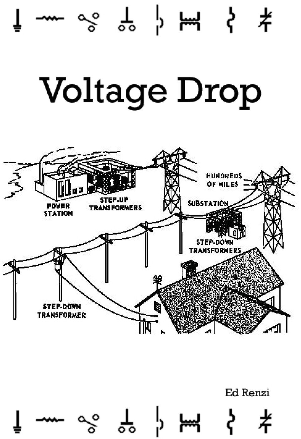
Voltage Drop (Single-Phase)
|
|
|
- Opal Adams
- 10 years ago
- Views:
Transcription
1
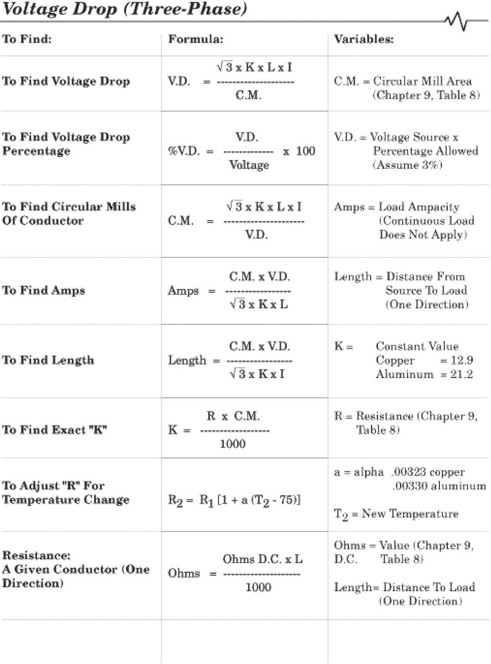
2 Voltage Drop (Single-Phase) To Find: To Find Voltage Drop Formula: 2 x K x L x I V.D. = C.M. Variables: C.M. = Circular Mill Area (Chapter 9, Table 8) To Find Voltage Drop Percentage V.D. %V.D. = x 100 Voltage V.D. = Voltage Source x Percentage Allowed (Assume 3%) To Find Circular Mills Of Conductor 2 x K x L x I C.M. = V.D. Amps = Load Ampacity (Continuous Load Does Not Apply) To Find Amps C.M. x V.D. Amps = x K x L Length = Distance From Source To Load (One Direction) To Find Length C.M. x V.D. Length = x K x I K = Constant Value Copper = 12.9 Aluminum = 21.2 To Find Exact "K": R x C.M. K = R = Resistance (Chapter 9, Table 8) Resistance: A Given Conductor (One Direction) Ohms D.C. x L Ohms = Ohms = Value (Chapter 9, D.C. Table 8) Length= Distance To Load (One Direction)
 Resistance: A Given Conductor (One Direction) Ohms D.C. x L Ohms = -------------------- 1000 Ohms = Value (Chapter 9, D.")
3 Voltage Drop Calculations Series Circuit In a series circuit, voltage (electro-motive force) pushes current (electrons) through a single path (conductor) around a circuit and back to its power source. A portion of this voltage is dropped off at each resistor and, by the time all of the voltage passes through all of the resistors, the total voltage is used up. This is consistent with Kirchoff s Law, which states that the sum of the voltages dropped at each resistor is equal to the source voltage. Notice the series circuit below, all of the voltages used at all of the resistors add up to 24 volts. Also, all of the resistances add up to the total resistance of the circuit, This is because all of the resistance in a series circuit is accumulated along a single path. In this case 12 ohms. 4 volts 2 ohms Parallel Circuit 24 volts 12 ohms 8 volts 4 ohms 12 volts 6 ohms In a parallel circuit, all of the voltage at the source is available to each resistor, even though there are several paths for current to travel. Notice in the parallel circuit below; the entire 12 volts at the source is available at each resistor. Resistance in a parallel circuit is not accumulated, or added together along one path, like a series circuit. The reason why is that the voltage, or force, is the same everywhere in the circuit. 12 volts 1.1 ohms 12 volts 2 ohms 12 volts 4 ohms 12 volts 6 ohms Resistance (Good And Bad) Up to now we have been talking about resistors as symbols in a circuit diagram. Most resistors, like light bulbs, toasters and electric heaters, in reality, are very useful devices. Even though these gizmos serve useful purposes by using electricity to do actual work, they aren t perfect, and to some extent waste energy. A light bulb for instance gives off light but, at the same time gives off unneeded (wasted) heat. Copper and aluminum conductors also are a little imperfect and contain some resistance. Chapter 9, Table 8 in the National Electrical Code gives us the actual resistance of conductors (per 1000 feet).

4 Notice the three columns on the right side of the Table. Copper Uncoated, Copper Coated and Aluminum. Copper Uncoated includes most conductors, like thermoplastic insulated and others. Copper Coated conductors includes rubber insulated (R-series) conductors which require an outer coating to keep the insulation from stretching. Aluminum conductors are listed on the last column. Remember, the resistances given in Chapter 9, Table 8 are per 1000 feet. The resistance per 1000 feet of #14 stranded copper wire (quantity 7, i.e. strands) for instance is 3.14 ohms, while the resistance of #14 solid copper wire (quantity 1) is 3.07 ohms. As you can see, there is less resistance in a solid wire than in a stranded. As you know, most conductors come in rolls of 500 feet, so the values in the Table will have to be adjusted for different lengths. Here s a formula for finding resistance for conductors of varying lengths: R = Ω (Table 8) x Length 1000
 is 3.07 ohms. As you can see, there is less resistance in a solid wire than in a stranded.")
5 Keep in mind that this formula calculates the resistance of one conductor only. To find the resistance of two conductors you ll have to double the resistance, etc. For conductors in parallel, you must halve the resistance, (or divide by 2). This is because two conductors in parallel are taking the place of one conductor. Conductor Resistance Problems... (1) The resistance of 500 feet of #4/0 copper wire is ohms? (a).1 Ω (b).528 Ω (c).0608 Ω (d).0304 Ω (2) The resistance of parallel 500 kcmil THW conductors located 250 feet from a panel is nearest to ohms. (a) Ω (c) Ω (b) Ω (d) Ω Calculating Voltage Drop The simplest way to calculate the voltage drop on conductors in a circuit you can use the formula... Check the following circuit... V.D. = I x R 120 Volts 3 Amp Load 175 #14 solid copper wire In the above circuit the amps (I) equals 3. The resistance (R) for 350 ( 175 times two conductors) of #14 copper wire (3.07 x 350 )/1000 = 1.07 ohms. The V.D. = I x R formula should look like this... V.D. = 3 x 1.07 or 3.21 volts dropped
 The resistance of parallel 500 kcmil THW conductors located 250 feet from a panel is nearest to ohms. (a).00645 Ω (c).00323 Ω (b).00581 Ω (d).")
6 How about this one Volts 20 Amp Load 250 #12 stranded copper wire In this circuit there are 20 amps (I). The resistance (R) for 500 ( 250 times two conductors) of #12 copper wire (1.98 x 500 )/1000 = 0.99 ohms. The V.D. = I x R formula should look like this... V.D. = 20 x 0.99 or 19.8 volts dropped Voltage Drop Allowed The National Electrical Code has some recommendations as to how much voltage drop loss can be tolerated on conductors. Here they are... For Branch Circuits , FPN No. 4: Conductors for Branch Circuits (as defined in Article 100), sized to prevent a voltage drop exceeding 3 percent (at the farthest outlet of power, heating, and lighting loads, or combinations of such loads) and a maximum total voltage drop on both feeders and branch circuits (to the farthest outlet) not to exceed 5 percent, will provide reasonable efficiency of operation. See FPN No. 2 of (A)(3) for voltage drop on feeder conductors. 5% Total 2% Feeder 3% Branch Circuit Between the power source (or service) and the farthest outlet of power, the Code allows a 5% voltage drop loss. So if we have 240 volts at the service, we would be allowed a 12 volt loss (or a minimum of 228 volts) at the farthest outlet. But, only a 3% voltage drop loss would be allowed between the panel and the last outlet. That s a maximum of 7.2 volts dropped on the branch circuit.

7 As far as Feeders are concerned FPN No. 2: Conductors for Feeders (as defined in Article 100), sized to prevent a voltage drop exceeding 3 percent (at the farthest outlet of power, heating, and lighting loads, or combinations of such loads) and a maximum total voltage drop on both feeders and branch circuits (to the farthest outlet) not to exceed 5 percent, will provide reasonable efficiency of operation. 5% Total 3% Feeder 2% Branch Circuit As before, between the power source or service and the farthest outlet of power, the Code allows a 5% voltage drop loss. But, in this case only a 3% voltage drop loss would be allowed between the service and the panel. So if we had 240 volts at the service, we would still be allowed a 12 volt loss (or 228 volts at the last outlet). But, a maximum 3% voltage drop loss would be allowed between the service and the panel. That s a maximum of 7.2 volts dropped on the feeder. Voltage Drop Problems... (3) The required diameter of an electrical conductor is determined by. (a) voltage (b) amperage (c) length (d) all of these (4) The branch circuit allowable voltage drop of a 230 volt circuit is. 2 x R x L 2 x R x I (a) C.M. (b) 230 x.03 (c) 5% (d) 6.9 volts 240 Volts (5) What does the National Electrical Code recommend for the voltage at the load in the above circuit? (a) (c) (b) (d) 228

8 Assume: On all branch circuits a 3% voltage drop is allowed unless we are given enough information as to what the actual voltage drop is. Voltage Drop Formulas Voltage drop can be lowered several ways. One way is to use a larger wire gauge because larger conductors have less resistance. Another way to lower resistance is to shorten the distance to the load. Also, increasing voltage will allow more volts to be dropped. Decreasing amps reduces the amount of current flowing on a circuit requiring a smaller wire size. To calculate how much voltage is dropped on the conductors of a circuit we use the following formula... 2 x K x L x I VD = CM Your probably wondering what all those letters (variables) stand for... VD of course stands for voltage drop. 2 represents the two conductors in a circuit. K is the constant or resistance factor (copper = 12.9, aluminum = 21.2). L is the length of the conductor in one direction (we automatically multiply that by 2). I stands for amps of the load. CM is the circular mill (thickness) of the conductor from Chapter 9, Table 8. Let s put this formula to work in a problem... A 240 volt, 25 amp heater is located 135 feet from a panel fed with two #10 THW conductors. Let s find the voltage drop of the circuit. Remember, we are trying to find the voltage drop of the circuit not the load. This is the wasted energy of the circuit not the energy used by the heater to do useful work, which is to keep us warm. Also, assume the conductor in the problem is copper, unless otherwise stated, (Article 110.5). O.K., the formula for voltage drop is: The variables are: VD = 2 x K x L x I CM K = 12.9 (copper) L = 135 I = 25 amps CM = 10,380 Chapter 9, Table 8 Plugging these values into the formula: 2 x 12.9 x 135 x 25 VD = 10,380 VD = 8.39

9 Remember, we re only allowed 3% voltage drop on our branch circuit. Here s a formula for finding percentage of voltage drop. VD %VD = Voltage x %VD = 240 x 100 %VD = 3.5% As you can see the percentage of voltage drop exceeds the 3% allowed for branch circuits. In fact 3% of 240 volts is only 7.2 volts, so we are 1.19 volts over the limit. We can solve this dilemma by choosing a new (larger conductor). Here s the formula for finding a new conductor... CM = 2 x K x L x I VD Now, let s remove the #10 THW conductors feeding the heater and find some new ones based on a voltage drop of 3% or 7.2 volts: The variables are: K = 12.9 (copper) L = 135 I = 25 amps VD = 7.2 (240 x.03) CM = 2 x K x L x I VD Plugging these values into the formula: 2 x 12.9 x 135 x 25 CM = 7.2 CM = If we use #8 copper conductors (Chapter 9, Table 8) we would have a total of 16,510 circular mills to work with. This would meet the requirement of at least 12,094 required by the formula.

10 More Voltage Drop Problems... (6) The voltage drop on two #12 THW solid copper conductors 150 feet long connecting a 1/2 horsepower (9.8 amp), single-phase motor to a 115 volt source would be volts. (a) 3.45 (c) 5.8 (b) 5 (d) 7.2 (7) The size wire is needed for a 115 volt, 30 amp load, located 120' from its voltage source is? (a) #4 (c) #8 (b) #6 (d) # Volts 1,265 Watts 115 Volts (8) The copper conductor size for the circuit diagram above is. (a) #4 (c) #8 (b) #6 (d) # Volts Amps (9) What is the circular mills with a voltage drop of 3% in the above diagram? (a) 21,000-25,000 (c) 221, ,000 (b) 200, ,000 (d) 231, ,000 (10) What size conductor is required for question (9)? (a) #250 kcmil (c) #3/0 (b) #4/0 (d) #2/0 (11) An 80' deep well is located 160' from the house panel. in the well is a 1/2 horsepower (9.8 amp), 115 volt pump. What copper wire size is required? (a) #10 (c) #6 (b) #8 (d) #4
 #4 (c) #8 (b) #6 (d) #10 220 Volts 350 180 Amps (9) What is the circular mills with a voltage drop of 3% in the above diagram?")
11 Finding Amps And Length Using The Voltage Drop Formulas... Here are some other related formulas: CM x VD This one determines conductor length... L = 2 x K x I CM x VD This one determines conductor amps... I = 2 x K x L Let s use these formulas in some problems... A short circuit has developed in a #14 copper wire. All 6 volts applied to the circuit are dropped and an amp meter reads 2 amps. Can you find the length of the conductor to the short? CM x VD Let s apply the formula for conductor length... L = 2 x K x I CM = 4,110 (#14) 4,110 x 6 VD = 6 (100% voltage drop) L = 2 x 12.9 x 2 K = 12.9 (copper) I = 2 amps L = feet Good luck tracking that short down! How about another one... Can you find the amps at the load of a 120 volt circuit, 143 feet long, using #12 THW aluminum conductors? CM x VD Let s apply the formula for amps at the load: I = 2 x K x L CM = 6,530 (#12) 6,530 x 3.6 VD = 3.6 (120 x.03) I = 2 x 21.2 x 143 K = 21.2 (aluminum) L = 143 I = 3.88 amps As you can see voltage drop can pay a high toll! A Mor e Precise K You might be wondering about K and where it came from? Well, K is based on the resistance of a circular mill of a conductor (copper or aluminum) by the foot. You can find it by this formula... R x CM K = 1000 Let s find K for a #14 stranded copper conductor x K = 1000 R = 3.14 (#14 stranded copper uncoated) CM = 4110 (#14 AWG) K = If we guessed 12.9 we would have been pretty close.
 I = 2 amps L = 477.9 feet Good luck tracking that short down! How about another one.")
12 Voltage Drop Sample Problem... There are two #1/0 THW aluminum wires feeding a 100 amp panel at a distance of 200 feet. What size copper wire could be used in order to have an equal voltage drop to the existing aluminum wires? Solution: To find the voltage drop of the #1/0 aluminum conductor: K (al) = 21.2 V.D. = 2 x K x L x I L = 200 C.M. I = 100 C.M. = 105,600 V.D. = 2 x 21.2 x 200 x ,600 V.D. = 8.03 (volts dropped) To find circular mills of equal copper wire: K(cu) = 12.9 C.M. = 2 x K x L x I L = 200 V.D. I = 100 V.D. = 8.03 C.M. = 2 x 12.9 x 200 x C.M. = 64,259 (Chapter 9, Table 8) #2 copper (66,360 C.M.) Replace the 1/0 aluminum wires with #2 copper wires.
 To find circular mills of equal copper wire: K(cu) = 12.9 C.M. = 2 x K x L x I L = 200 V.D. I = 100 V.D. = 8.03 C.M. = 2 x 12.")
13 More Voltage Drop Problems... (12) A load at 115 volts located 250 feet from a panel is fed with a #14 conductor. The amps at the load is approximately. (a) 8.2 amps (b) 3.5 amps (c) 2.2 amps (d) 1.7 amps (13) A #12 two conductor cable carrying 115 volts from the source is buried underground, it feeds a 16 amp motor. A reading shows volts at 16 amps at the motor. The length of the conductor is approximately feet. (a) 35 (c) 74 (b) 48 (d) 96 (14) A 45 amp load at 120 volts is located 400 feet from a panel. What size copper wire will be required? (a) #1/0 (c) #3/0 (b) #2/0 (d) #4/0 (15) A 3/4 horsepower pool pump (13.8 amps), rated 115 volts, is located 124 feet from the panel. What size copper wire is recommended? (a) #10 (c) #6 (b) #8 (d) #4
 #1/0 (c) #3/0 (b) #2/0 (d) #4/0 (15) A 3/4 horsepower pool pump (13.8 amps), rated 115 volts, is located 124 feet from the panel. What size copper wire is recommended?")
14 Voltage Drop Answers (1) B (3%) (2) D (3) D (240v x.03 = 12) (240v - 12v = 228v) (4) D (R =.0608 x 500) 1000 (5) A (CM = 2 x 12.9 x 120 x 30) 3.45 (6) D (CM = 2 x 12.9 x 180 x 11) 5 (7) D (CM = 2 x 12.9 x 350 x 180) 6.6 (8) A (9) B (Amps = 4110 x 3.45 ) 2 x 12.9 x 250 (10) C (Length = 6530 x 4.7 ) 2 x 12.9 x 16 (11) B (CM = 2 x 12.9 x 400 x 45) 3.6 (12) C (CM = 2 x 12.9 x 240 x 9.8) 3.45 (13) C (CM = 2 x 12.9 x 124 x 13.8) 3.45 (14) C (R =.0129 x 250) 1000
 B (CM = 2 x 12.9 x 400 x 45) 3.6 (12) C (CM = 2 x 12.9 x 240 x 9.8) 3.45 (13) C (CM = 2 x 12.")
15 Voltage Drop (New Method) To Find: Formula: Variables: To Find Voltage Drop 75 o C.) 2 x R x L x I V.D. = V.D. = Voltage Source x Percentage Allowed (Assume 3%) To Find Voltage Drop Percentage (@ 75 o C.) V.D. %V.D. = X 100 Voltage To Find Circular Mills Of Conductor (@ 75 o C.) V.D. x 1000 R = x L x I R = Resistance Value (Chapter 9, Table 8) To Find Amps (@ 75 o C.) V.D. x 1000 I = x R x L I = Load Ampacity (Continuous Load Does Not Apply) To Find Length (@ 75 o C.) V.D. x 1000 L = x R x I L = Distance From Source To Load (One Direction) Temperature Change Formula R2 = R1 [1 + a ( T2-75 )] R1 = Temperature Of Conductor At 75 o 75 o C.) T2 = New Temperature a = Copper Aluminum
![) V.D. x 1000 I = ----------------- 2 x R x L I = Load Ampacity (Continuous Load Does Not Apply) To Find Length (@ 75 o C.) V.D. x 1000 L = ----------------- 2 x R x I L = Distance From Source To Load (One Direction) Temperature Change Formula R2 = R1 [1 + a ( T2-75 )] R1 = Temperature Of Conductor At 75 o (Not @ 75 o C.](/docs-images/43/6038362/images/page_15.jpg ") T2 = New Temperature a =.00323 Copper.00330 Aluminum")
16
Voltage Loss Formula s
 www.litz-wire.com HM Wire International Inc. Phone: 330-244-8501 Fax: 330-244-8561 Voltage Loss Formula s www.hmwire.com Voltage loss in a wire is synonymous to pressure loss in a pipe. Electric current
Voltage Drop. Voltage Drop 1
 Voltage Drop The technical information provided herein is to assist qualifi ed persons in planning and installing electric service to farms and residences. Qualified person is defi ned in Article 100 of
CHAPTER 2 EXAMPLES AND TABLES
 CHAPTER 2 EXAMPLES AND TABLES COMMENTARY AT 210.20(A) EXCEPTION An overcurrent device that supplies continuous and noncontinuous loads must have a rating that is not less than the sum of 100 percent of
Line Loss WSDOT Winter 2008 BZA
 Electrical Design Training Class Line Loss WSDOT Winter 2008 BZA Presented by: Keith Calais 1 OHM S LAW P = Watts (Power) I = CURRENT (AMPERES) R = RESISTANCE (OHMS) E = ELECTROMOTIVE FORCE (VOLTS) P =
I = V/r P = VI. I = P/V = 100 W / 6 V = 16.66 amps. What would happen if you use a 12-volt battery and a 12-volt light bulb to get 100 watts of power?
 Volts, Amps and Ohms Measuring Electricity The three most basic units in electricity are voltage (V), current (I) and resistance (r). Voltage is measured in volts, current is measured in amps and resistance
7. What is the current in a circuit if 15 coulombs of electric charge move past a given point in 3 seconds? (1) 5 A (3) 18 A (2) 12 A (4) 45 A
 5 A (3) 18 A (2) 12 A (4) 45 A") 1. Compared to the number of free electrons in a conductor, the number of free electrons in an insulator of the same volume is less the same greater 2. Most metals are good electrical conductors because
1. Compared to the number of free electrons in a conductor, the number of free electrons in an insulator of the same volume is less the same greater 2. Most metals are good electrical conductors because
Short Circuit Current Calculations
 Introduction Several sections of the National Electrical Code relate to proper overcurrent protection. Safe and reliable application of overcurrent protective devices based on these sections mandate that
Copper wire figures. AWG Table
 Tyco Electronics Corporation Crompton Instruments 1610 Cobb International Parkway, Unit #4 Kennesaw, GA 30152 Tel. 770-425-8903 Fax. 770-423-7194 Copper wire figures NOTE: This information and the circuits
rpsa FIRE PROTECTION ENGINEERS
 R.P. SCHIFILITI ASSOCIATES, INC. P.O. Box 297 Reading, Massachusetts 01867-0497 USA 781.944.9300 Fax / Data 781.942.7500 Telephone Sample Fire Alarm System Calculations 1. A fire alarm manufacturer specifies
Ohm's Law and Circuits
 2. Conductance, Insulators and Resistance A. A conductor in electricity is a material that allows electrons to flow through it easily. Metals, in general, are good conductors. Why? The property of conductance
GENERATOR SELECTION. a. Three phase - 120/208V, 3 phase, 4W wye; 277/408, 3 phase, 4W wye; * 120/240V 3 phase, 4W Delta
 GENERATOR SELECTION Generators must be sized to handle their load based on the continuous KW, kilowatt load, and KVA, kilovoltamp load, and the worst case starting load KW + KVA. They must be derated for
Objectives 200 CHAPTER 4 RESISTANCE
 Objectives Explain the differences among conductors, insulators, and semiconductors. Define electrical resistance. Solve problems using resistance, voltage, and current. Describe a material that obeys
BASIC NEC CODE RULES AND DESIGN PRACTICE
 BASIC NEC CODE RULES AND DESIGN PRACTICE Wire Ampacity and Size Circuit Breaker Size 1. Maximum loading for any branch circuit is 80% of rating of circuit for ampacity of wire for any load. NEC 220-2,
People s Physics Book
 The Big Ideas: The name electric current is given to the phenomenon that occurs when an electric field moves down a wire at close to the speed of light. Voltage is the electrical energy density (energy
HOW TO CORRECTLY CONNECT DEEP CYCLE BATTERIES AND CHOOSE THE RIGHT CABLE SIZING
 HOW TO CORRECTLY CONNECT DEEP CYCLE BATTERIES AND CHOOSE THE RIGHT CABLE SIZING There are several ways to wire multiple batteries to achieve the correct battery voltage or capacity for a particular DC
Department of Labor and Industry Electrical Licensing
 Department of Labor and Industry Electrical Licensing License Examination Guide The information in this guide is provided by the Licensing Unit of the Department of Labor and Industry to ensure that applicants
An Electrical Lab Exercise on Voltage Drop
 An Electrical Lab Exercise on Voltage Drop Mark C. Tatum, P.E. Auburn University Auburn, AL Lab exercises are an excellent way to give students hands on experiences. Practice by doing has been demonstrated
Current Transformer (CT) Selection Guide
 Selection Guide") Current Transformer (CT) Selection Guide Article ESA-1008D December 5, 2014 Contents 1 Introduction.............................................. 3 1.1 Extending CT leads.......................................
Current Transformer (CT) Selection Guide Article ESA-1008D December 5, 2014 Contents 1 Introduction.............................................. 3 1.1 Extending CT leads.......................................
Series and Parallel Circuits
 Series and Parallel Circuits Direct-Current Series Circuits A series circuit is a circuit in which the components are connected in a line, one after the other, like railroad cars on a single track. There
ELECTRICAL CIRCUITS. Electrical Circuits
 Electrical Circuits A complete path, or circuit, is needed before voltage can cause a current flow through resistances to perform work. There are several types of circuits, but all require the same basic
PS-6.2 Explain the factors that determine potential and kinetic energy and the transformation of one to the other.
 PS-6.1 Explain how the law of conservation of energy applies to the transformation of various forms of energy (including mechanical energy, electrical energy, chemical energy, light energy, sound energy,
Electrical Fundamentals Module 3: Parallel Circuits
 Electrical Fundamentals Module 3: Parallel Circuits PREPARED BY IAT Curriculum Unit August 2008 Institute of Applied Technology, 2008 ATE310- Electrical Fundamentals 2 Module 3 Parallel Circuits Module
Errors Related to Cable Resistance Imbalance in Three Wire RTDs
 Errors Related to Cable Resistance Imbalance in Three Wire RTDs 1.0 Introduction There are multiple sources of error that can impact the accuracy of an RTD measurement. The cable incorporated into the
Wire types and sizes
 Wire types and sizes This worksheet and all related files are licensed under the Creative Commons Attribution License, version 1.0. To view a copy of this license, visit http://creativecommons.org/licenses/by/1.0/,
Electrical Design TABLE OF CONTENTS FOREWORD... 1. BASIC ELEMENTS OF ELECTRICITY... 2 Electricity works much like water Ohm s Law
 TABLE OF CONTENTS Electrical Design TABLE OF CONTENTS FOREWORD.......................................................................... 1 BASIC ELEMENTS OF ELECTRICITY..................................................
Student Exploration: Circuits
 Name: Date: Student Exploration: Circuits Vocabulary: ammeter, circuit, current, ohmmeter, Ohm s law, parallel circuit, resistance, resistor, series circuit, voltage Prior Knowledge Questions (Do these
East Central College 14434.03 HANSEN HALL LEVEL 300/400 RENOVATIONS PACKAGE
 SECTION 260519 - BUILDING WIRE AND CABLE PART 1 - GENERAL 1.1 WORK INCLUDES A. Base and Alternate Bids: 1. Contractor Provide: a. Building wire and cable as shown on drawings or specified including feeders,
Series and Parallel Circuits
 Series and Parallel Circuits Components in a circuit can be connected in series or parallel. A series arrangement of components is where they are inline with each other, i.e. connected end-to-end. A parallel
Beware of Simplistic Voltage Drop Calculations. By Aaron Hesse, PE, Coffman Engineers, Spokane, Washington INTRODUCTION
 Subject: Beware of Simplistic Voltage Drop Calculations By Aaron Hesse, PE, Coffman Engineers, Spokane, Washington INTRODUCTION Iterative voltage drop calculations are some of the most tedious and time
Physics 3330 Experiment #2 Fall 1999. DC techniques, dividers, and bridges R 2 =(1-S)R P R 1 =SR P. R P =10kΩ 10-turn pot.
R P R 1 =SR P. R P =10kΩ 10-turn pot.") Physics 3330 Experiment #2 Fall 1999 DC techniques, dividers, and bridges Purpose You will gain a familiarity with the circuit board and work with a variety of DC techniques, including voltage dividers,
Physics 3330 Experiment #2 Fall 1999 DC techniques, dividers, and bridges Purpose You will gain a familiarity with the circuit board and work with a variety of DC techniques, including voltage dividers,
Chapter 9. Bonding and Grounding
 Chapter 9 Bonding and Grounding Objectives Describe why the cable should be bonded Describe bonding and grounding procedures Define Bonding and Grounding Explain Safety Benefits and intent of bonding and
Experiment NO.3 Series and parallel connection
 Experiment NO.3 Series and parallel connection Object To study the properties of series and parallel connection. Apparatus 1. DC circuit training system 2. Set of wires. 3. DC Power supply 4. Digital A.V.O.
OHM S LAW AND RESISTANCE
 OHM S LAW AND RESISTANCE Resistance is one of the basic principles of Ohm s law, and can be found in virtually any device used to conduct electricity. Georg Simon Ohm was a German physicist who conducted
AJ s Technical Tips: Designing a Small Solar PV System Part IV; Selecting Wires for the System
 AJ s Technical Tips: Designing a Small Solar PV System Part IV; Selecting Wires for the System A little while back Simon Nyukuri of Kitale wrote to ask me about sizing wires and cables for solar PV systems.
Electrician s Math and Basic Electrical Formulas
 UNIT 1 Electrician s Math and Basic Electrical Formulas INTRODUCTION TO UNIT 1 ELECTRICIAN S MATH AND BASIC ELECTRICAL FORMULAS In order to construct a building that will last into the future, a strong
How Much Voltage Drop Is Acceptable?
 How Much Voltage Drop Is Acceptable? Article supplied by Ideal The National Electrical Code (NEC) recommends that the combined voltage drop of the electrical system (branch circuit and feeders) not exceed
Branch Circuit Calculations
 Branch Circuit Calculations by Gerald Newton October 31, 1999 1. A 20 ampere, 120 volt, 2-wire branch circuit has a maximum load capacity of watts or volt-amperes. Reference: Using the following for Single
Three-Phase Electric Power Distribution for Computer Data Centers
 Three-hase Electric ower Distribution for Computer Data Centers WHITE AER E901 Geist January 008 Summary This paper will describe the characteristics of three-phase power and outline the advantages of
Electrical Design Training Class Ampacity WSDOT Winter 2008 BZA
 Electrical Design Training Class Ampacity WSDOT Winter 2008 BZA presented by: Keith Calais 1 What is it? Ampacity is the current, in Amperes, that a conductor can carry continuously under the conditions
Section B: Electricity
 Section B: Electricity We use mains electricity, supplied by power stations, for all kinds of appliances in our homes, so it is very important to know how to use it safely. In this chapter you will learn
PHYSICS 111 LABORATORY Experiment #3 Current, Voltage and Resistance in Series and Parallel Circuits
 PHYSCS 111 LABORATORY Experiment #3 Current, Voltage and Resistance in Series and Parallel Circuits This experiment is designed to investigate the relationship between current and potential in simple series
How To Wire A Three Phase, Single Phase, Wye Transformer
 Three-Phase Transformers When more power is needed - three transformers can be tied together. This is called three-phase. Here s a simple way of comparing single-phase to threephase power. Single-Phase
AP Physics Electricity and Magnetism #4 Electrical Circuits, Kirchoff s Rules
 Name Period AP Physics Electricity and Magnetism #4 Electrical Circuits, Kirchoff s Rules Dr. Campbell 1. Four 240 Ω light bulbs are connected in series. What is the total resistance of the circuit? What
Introduction to Electricity & Magnetism. Dr Lisa Jardine-Wright Cavendish Laboratory
 Introduction to Electricity & Magnetism Dr Lisa Jardine-Wright Cavendish Laboratory Examples of uses of electricity Christmas lights Cars Electronic devices Human body Electricity? Electricity is the presence
Resistors. Some substances are insulators. A battery will not make detectible current flow through them.
 Resistors Some substances are insulators. A battery will not make detectible current flow through them. Many substances (lead, iron, graphite, etc.) will let current flow. For most substances that are
ELECTRICAL FUNDAMENTALS
 General Electricity is a form of energy called electrical energy. It is sometimes called an "unseen" force because the energy itself cannot be seen, heard, touched, or smelled. However, the effects of
PS4-24 OWNERS MANUAL 24 VAC 90 WATT WALL MOUNTED CCTV POWER SUPPLY
 PS4-24 OWNERS MANUAL 24 VAC 90 WATT WALL MOUNTED CCTV POWER SUPPLY 7320 Ashcroft, Suite 104 Houston, Texas 77081 p: 713-772-1404 f: 713-772-7360 e: [email protected] www.juicegoose.com 06-06 CONGRATULATIONS
POWER AND VOLTAGE RATING
 POWER AND VOLTAGE RATING SCOPE: The purpose of this document is to take the confusion out of power and voltage ratings in specifications and in product information publications. This will be accomplished
6/14/02 Chapter 14: Use of Electrical Test Equipment 1/20
 USE OF ELECTRICAL TEST EQUIPMENT Test equipment is necessary for determining proper set-up, adjustment, operation, and maintenance of electrical systems and control panels. The following is a general procedure
ELECTRICITY (E) So, what is this mysterious stuff that we call E? Where does it come from? Where does it go and why is it
 So, what is this mysterious stuff that we call E? Where does it come from? Where does it go and why is it") ELECTRICITY (E) Electricity how it works, how we measure and pay for it. INTRODUCTION: HOW ELECTRICITY WORKS: E completely surrounds us. Modern life would be rather primitive without it. A few examples
ELECTRICITY (E) Electricity how it works, how we measure and pay for it. INTRODUCTION: HOW ELECTRICITY WORKS: E completely surrounds us. Modern life would be rather primitive without it. A few examples
NAME: DATE: (Please Print) RESISTOR NETWORK AND OHMS LAW PRACTICE EXAM (See formulas at the back of this exam) 120 Volts AC 35 Ohms
 RESISTOR NETWORK AND OHMS LAW PRACTICE EXAM (See formulas at the back of this exam) 120 Volts AC 35 Ohms") NAM: DAT: (lease rint) RSISTOR NTWORK AND OHMS LAW RACTIC XAM (See formulas at the back of this exam) 25 Ohms 120 Volts AC 35 Ohms 1. Based on the drawing above, what is the total circuit resistance? This
NAM: DAT: (lease rint) RSISTOR NTWORK AND OHMS LAW RACTIC XAM (See formulas at the back of this exam) 25 Ohms 120 Volts AC 35 Ohms 1. Based on the drawing above, what is the total circuit resistance? This
Odyssey of the Mind Technology Fair. Simple Electronics
 Simple Electronics 1. Terms volts, amps, ohms, watts, positive, negative, AC, DC 2. Matching voltages a. Series vs. parallel 3. Battery capacity 4. Simple electronic circuit light bulb 5. Chose the right
TECH TIP # 37 SOLVING SERIES/PARALLEL CIRCUITS THREE LAWS --- SERIES CIRCUITS LAW # 1 --- THE SAME CURRENT FLOWS THROUGH ALL PARTS OF THE CIRCUIT
 TECH TIP # 37 SOLVING SERIES/PARALLEL CIRCUITS Please study this Tech Tip along with assignment 4 in Basic Electricity. Parallel circuits differ from series circuits in that the current divides into a
Tutorial 12 Solutions
 PHYS000 Tutorial 2 solutions Tutorial 2 Solutions. Two resistors, of 00 Ω and 200 Ω, are connected in series to a 6.0 V DC power supply. (a) Draw a circuit diagram. 6 V 00 Ω 200 Ω (b) What is the total
Constant Current Electronic Power Supply Load By Jeff K. Steinkamp N7YG April 3, 2012
 Constant Current Electronic Power Supply Load By Jeff K. Steinkamp N7YG April 3, 2012 Power supplies, especially external units, have become an ever increasing necessity in today s world of electronic
BRANCH CIRCUIT AND FEEDER REQUIREMENTS
 CHAPTER 36 BRANCH CIRCUIT AND FEEDER REQUIREMENTS SECTION E3601 GENERAL E3601.1 Scope. This chapter covers branch circuits and feeders and specifies the minimum required branch circuits, the allowable
FB-DC3 Electric Circuits: Series and Parallel Circuits
 CREST Foundation Electrical Engineering: DC Electric Circuits Kuphaldt FB-DC3 Electric Circuits: Series and Parallel Circuits Contents 1. What are "series" and "parallel"? 2. Simple series circuits 3.
SOLAR PV STANDARD ELECTRICAL PLAN Microinverter Systems for Single Family Dwellings
 *** Provide this document to the inspector along with ALL system installation instructions *** Project Address: Scope: Standard plan for the installation of grounded microinverter solar PV systems, not
3.- What atom s particle moves through a conductor material? 4.- Which are the electric components of an elemental electric circuit?
 1.- What is electricity? 2.- Write down the name of the atom s particles. 3.- What atom s particle moves through a conductor material? 4.- Which are the electric components of an elemental electric circuit?
Parallel Circuits. Objectives After studying this chapter, you will be able to answer these questions: 1. How are electrical components connected
 This sample chapter is for review purposes only. Copyright The Goodheart-Willcox Co., Inc. All rights reserved. Electricity Objectives After studying this chapter, you will be able to answer these questions:.
Electrical Circuit Theory
 Electrical Circuit Theory Learning Objectives: 1. Review the basic electrical concepts of voltage, amperage, and resistance. 2. Review the components of a basic automotive electrical circuit. 3. Introduce
INSTALLATION GUIDE LOW VOLTAGE TRANSFORMER
 INSTALLATION GUIDE LOW VOLTAGE TRANSFORMER 300W 600W 900W 1200W ATTENTION: Please read and understand thoroughly this installation guide to ensure safe and efficient operation of this Power Module 1 Open
Table of Contents. The Basics of Electricity 2. Using a Digital Multimeter 4. Testing Voltage 8. Testing Current 10. Testing Resistance 12
 Table of Contents The Basics of Electricity 2 Using a Digital Multimeter 4 IDEAL Digital Multimeters An Introduction The Basics of Digital Multimeters is designed to give you a fundamental knowledge of
WIRE, TERMINAL AND CONNECTOR REPAIR CONDUCTORS
 CONDUCTORS Conductors are needed to complete the path for electrical current to flow from the power source to the working devices and back to the power source. Special wiring is needed for battery cables
CHAPTER 4 UTILITY SYSTEMS ELECTRICAL. Utility Systems Electrical. Main Panel
 CHAPTER 4 UTILITY SYSTEMS ELECTRICAL Utility Systems Electrical The electrical supply to your home begins outside, where you will see either an overhead feed and piping down the side of your home or (if
Parallel DC circuits
 Parallel DC circuits This worksheet and all related files are licensed under the Creative Commons Attribution License, version 1.0. To view a copy of this license, visit http://creativecommons.org/licenses/by/1.0/,
A Learning Guide for Model Rocket Launch Systems
 A Learning Guide for Model Rocket Launch Systems Including: Schematics, Electrical Theory and Study Problems Edited and updated by Ann Grimm EstesEducator.com [email protected] 800.820.0202 2012
STUDY GUIDE: ELECTRICITY AND MAGNETISM
 319 S. Naperville Road Wheaton, IL 60187 www.questionsgalore.net Phone: (630) 580-5735 E-Mail: [email protected] Fax: (630) 580-5765 STUDY GUIDE: ELECTRICITY AND MAGNETISM An atom is made of three
Electric Motor Brake Horsepower Calculations
 Electric Motor Brake Horsepower Calculations By Norm Christopherson These motor calculations are contained here as they apply to the changing conditions of the blower motor when pulley adjustments are
Ohm s Law. George Simon Ohm
 Ohm s Law George Simon Ohm The law which governs most simple and many complex electrical phenomena is known as Ohm s Law. It is the most important law in electricity. In 1827, a German locksmith and mathematician
Forms of Energy. Freshman Seminar
 Forms of Energy Freshman Seminar Energy Energy The ability & capacity to do work Energy can take many different forms Energy can be quantified Law of Conservation of energy In any change from one form
1. The diagram below represents magnetic lines of force within a region of space.
 1. The diagram below represents magnetic lines of force within a region of space. 4. In which diagram below is the magnetic flux density at point P greatest? (1) (3) (2) (4) The magnetic field is strongest
Fundamentals of Power
 Fundamentals of Power Fundamentals of Power 2008 American Power Conversion Corporation. All rights reserved. All trademarks provided are the property of their respective owners. Learning Objectives At
Radial Distribution Test Feeders
 Radial Distribution Test Feeders Distribution System Analysis Subcommittee Report Abstract: Many computer programs are available for the analysis of radial distribution feeders. In 1992 a paper was published
13.10: How Series and Parallel Circuits Differ pg. 571
 13.10: How Series and Parallel Circuits Differ pg. 571 Key Concepts: 5. Connecting loads in series and parallel affects the current, potential difference, and total resistance. - Using your knowledge of
Lab 3 - DC Circuits and Ohm s Law
 Lab 3 DC Circuits and Ohm s Law L3-1 Name Date Partners Lab 3 - DC Circuits and Ohm s Law OBJECTIES To learn to apply the concept of potential difference (voltage) to explain the action of a battery in
Current Electricity Lab Series/Parallel Circuits. Safety and Equipment Precautions!
 Current Electricity Lab Series/Parallel Circuits Name Safety and Equipment Precautions! Plug in your power supply and use ONLY the D.C. terminals of the power source, NOT the A. C. terminals. DO NOT touch
Conductor Sizing and the National Electrical Code
 Conductor Sizing and the National Electrical Code The National Electrical Code requirements for conductor sizing and overcurrent protection have always been confusing and complex. Factors that must be
Chapter 13: Electric Circuits
 Chapter 13: Electric Circuits 1. A household circuit rated at 120 Volts is protected by a fuse rated at 15 amps. What is the maximum number of 100 watt light bulbs which can be lit simultaneously in parallel
Cable Tray Selection-
 Cable Selection- For allowable cable types see the Appendix page A-9. The following guidelines are based on the 2002 National Electrical Code, Article 392. I) Number of Multiconductor Cables rated 2000
MULTIPLE CHOICE. Choose the one alternative that best completes the statement or answers the question.
 MULTIPLE CHOICE. Choose the one alternative that best completes the statement or answers the question. 1) If the voltage at a point in space is zero, then the electric field must be A) zero. B) positive.
Circuits and the Flow of Electricity
 Lesson Overview This lesson helps Girl Scouts learn about how electricity works within a simple circuit. Many vocabulary words must be introduced (located under things for the leader to know). This lesson
SECTION 4 ELECTRIC MOTORS UNIT 17: TYPES OF ELECTRIC MOTORS
 SECTION 4 ELECTRIC MOTORS UNIT 17: TYPES OF ELECTRIC MOTORS UNIT OBJECTIVES After studying this unit, the reader should be able to Describe the different types of open single-phase motors used to drive
Electrical for Detached Garages: Updated Feb 19, 2016 for 2015 CE Code in force Jan. 1, 2016. Underground branch circuit feeding a detached garage:
 Electrical for Detached Garages: Updated Feb 19, 2016 for 2015 CE Code in force Jan. 1, 2016 * Garage construction requires permits (electrical, building) * Permits must be applied for at the time. * Dial
BERTHOLD ELECTRIC GENERATOR CONNECTION CABINET
 BERTHOLD ELECTRIC GENERATOR CONNECTION CABINET Berthold Electric Company s Generator Connection Cabinet provides a quick and convenient station to connect a portable generator to a facility s main service
Current, Resistance and Electromotive Force. Young and Freedman Chapter 25
 Current, Resistance and Electromotive Force Young and Freedman Chapter 25 Electric Current: Analogy, water flowing in a pipe H 2 0 gallons/minute Flow Rate is the NET amount of water passing through a
Lab 2: Resistance, Current, and Voltage
 2 Lab 2: Resistance, Current, and Voltage I. Before you come to la.. A. Read the following chapters from the text (Giancoli): 1. Chapter 25, sections 1, 2, 3, 5 2. Chapter 26, sections 1, 2, 3 B. Read
Current Transformers
 Tyco Electronics Corporation Crompton Instruments 1610 Cobb International Parkway, Unit #4 Kennesaw, GA 30152 Tel. 770-425-8903 Fax. 770-423-7194 Current Transformers Current transformers (CT's) provide
GUIDELINES FOR WIRING SINGLE FAMILY DWELLING UNITS
 GUIDELINES FOR WIRING SINGLE FAMILY DWELLING UNITS This guideline has been prepared to assist the owner/occupant of a single family dwelling with compliance to the requirements of the National Electrical
Home Build Solar System is the website where you can get the information you need to build your own solar system.
 Home Build Solar System Home Build Solar System is the website where you can get the information you need to build your own solar system. The initial intention I could see that my electricity bill was
Resistors in Series and Parallel
 Resistors in Series and Parallel Bởi: OpenStaxCollege Most circuits have more than one component, called a resistor that limits the flow of charge in the circuit. A measure of this limit on charge flow
Measurement of Capacitance
 Measurement of Capacitance Pre-Lab Questions Page Name: Class: Roster Number: Instructor:. A capacitor is used to store. 2. What is the SI unit for capacitance? 3. A capacitor basically consists of two
Tristan s Guide to: Solving Series Circuits. Version: 1.0 Written in 2006. Written By: Tristan Miller [email protected]
 Tristan s Guide to: Solving Series Circuits. Version: 1.0 Written in 2006 Written By: Tristan Miller [email protected] Series Circuits. A Series circuit, in my opinion, is the simplest circuit
Cable Selection for Medium Voltage Capacitor Banks and Harmonic Filter Banks
 Cable Selection for Medium Voltage Capacitor Banks and Harmonic Filter Banks Introduction This document presents the fundamental aspects of cable and conductor selection for connecting pad mounted shunt
ELECTRIC FIELD LINES AND EQUIPOTENTIAL SURFACES
 ELECTRIC FIELD LINES AND EQUIPOTENTIAL SURFACES The purpose of this lab session is to experimentally investigate the relation between electric field lines of force and equipotential surfaces in two dimensions.
Self-Regulating Low Temperature Heating Cable
 PDS SRL Self-Regulating Low Temperature Heating Cable Self-Regulating, Energy Efficient 16 AWG Buss Wire Circuit Lengths to 660 Feet Process Temperature Maintenance to 150 F (65 C) Maximum Continuous Exposure
Electrical Drawings - Table of Contents
 Electrical Drawings - Table of Contents E1.0 Lighting Plan E1.1 Power Plan E2.0 Electrical Specifications E2.1 Electrical Specifications E3.0 Panel Schedule E3.1 Load Summary 1 2 1 Panel Schedule LP1