AutoCAD Electrical Symbol Libraries
|
|
|
- Noel Morgan
- 9 years ago
- Views:
Transcription
1 AutoCAD Electrical Symbol Libraries AutoCAD Electrical 2005 Symbol file names should conform to the AutoCAD Electrical naming convention. Though not mandatory, you are encouraged to follow the convention in order to take full advantage of the AutoCAD Electrical features. Library Symbol Naming Conventions Using Multiple Symbol Libraries Substituting Symbols in the Library Schematic Library Symbols The following pages describe the naming conventions that should be followed when you create or modify library symbols.

2 Library Symbol Naming Conventions The default symbol subdirectory, jic1, and a companion uniform text height library, jic125, each contain many hundreds of component symbols in standard AutoCAD ".dwg" file format. These are referenced by AutoCAD Electrical and its icon menuing system and are inserted as standard AutoCAD blocks with attributes. Cable Marker Symbols AutoCAD Electrical cable conductor marker symbols follow this convention: The first character is H or V for horizontal or vertical wire insertion. The next two characters are W0. A zero (0) means that the symbol does not trigger a wire number change through it. The fourth character is 1 or 2. 1 = parent marker; 2 = child marker The remaining characters are not specified. Examples HW01.dwg HW02.dwg VW01.dwg VW02.dwg parent cable conductor marker, horizontal wire insertion child cable marker, horizontal wire insertion parent cable conductor marker, vertical wire insertion child cable marker, vertical wire insertion Component Location Mark Symbols AutoCAD Electrical expects the location symbol names to begin with the characters WDXX. 2

3 Configuration and Ladder Master Line Reference Symbols AutoCAD Electrical expects to find these block inserts: WD_M.dwg WD_PNLM. dwg WD_MLRH. dwg WD_MLRV.dwg WD_MLRHX. dwg WD_MLRVX. dwg block insert consisting of about 50 invisible attributes. These carry the drawing s settings. optional block insert consisting of several invisible attributes. These carry the drawing s settings for panel layout functions. block insert that carries a ladder s first line reference number and additional information such as rung spacing and ladder length. same as above but for a ladder that lies on its side. optional, user-defined alternative to WD_MLRH.dwg. This symbol name is used by AutoCAD Electrical when you select User Block from the Referencing tab on the Drawing Configuration dialog box. same as above but for a ladder that lies on its side. NOTE The ladder line reference block used by AutoCAD Electrical is determined by the ladder reference configuration selected in the Referencing tab on the Drawing Configuration dialog box. Dumb In-Line Wire Marker Symbols Dumb in-line wire marker symbols must be constructed with a tiny piece of "pigtail" line entity at each connection point. This can be very small but it needs to be present for AutoCAD Electrical to correctly see the in-line inserted block as it traces the wire network. In-line wire marker symbols follow this naming convention: The first character is H or V for horizontal wire or vertical wire insertion. The next three characters are T0_. The remaining characters are undefined. Example HT0_RED.dwg red in-line marker, horizontal wire insert 3

4 General Components Schematic components such as relays, switches, pilot lights, and discrete motor control devices (but not PLC I/O symbols) follow this naming convention: 32 character block name maximum; the first character is either H or V for horizontal or vertical wire insertion. The next two characters are reserved for family type (such as PB for push buttons, CR for control relays, or LS for limit switches). A zero (0) as the second character of the family type means that the symbol does not trigger a wire number change through it (for example, T0 for terminals, W0 for cable markers, and so on). The fourth character is generally a 1 or 2. 1 = parent or stand-alone components; 2 = child contacts If the symbol is a contact, the fifth character is a 1 or 2. 1 = normally open; 2 = normally closed. The remaining characters are not specified. They are used to keep names unique. Examples HCR1.dwg VCR1.dwg HCR21.dwg HCR22.dwg HCR22T.dwg VPB11.dwg VPB21.dwg HLS11.dwg HLS11H.dwg VLT1RP.dwg HW01.dwg control relay coil, horizontal rung insertion control relay coil, vertical rung insertion horizontal relay contact, N.O. horizontal relay contact, N.C. horizontal relay contact, N.C. with in-line terminal numbers vertical push button, parent contact, N.O. vertical push button, child contact, N.O. horizontal limit switch, parent, N.O. horizontal limit switch, parent, N.O. Held closed vertical pilot light, red, press-to-test horizontal cable marker, no wire number change through it 4
 as the second character of the family type means that the symbol does not trigger a wire number change through it (for example, T0 for terminals, W0 for cable markers, and so on).")
5 Panel Layout Footprint Symbols There isn t a required naming convention to follow, but the name must adhere to the AutoCAD 32-character block name limit. PLC I/O Parametric Build Symbols These symbols begin with "HP" or "VP" (horizontal rung versus vertical) followed by a digit 1 through 9. The digit corresponds to the selected PLC module style or "look" (1 through 5 are provided in the AutoCAD Electrical library, 6 through 9 can be user-defined). Plug/Jack Connector Pin Symbols AutoCAD Electrical connector symbols follow this convention: The first character is H or V for horizontal or vertical wire insertion. The next two characters are C0 if the connector doesn t trigger a wire number change through it, or CN if the connector triggers a wire number change. The fourth character is 1 or 2. 1 = parent marker; 2 = child marker The remaining characters are not specified. Source/Destination Wire Signal Arrow Symbols AutoCAD Electrical wire signal arrow symbols follow this convention: The first four characters of these symbol names are either "HA?S" for source signal arrows or "HA?D" for destination symbol arrows. The "?" character is the arrow style digit (1 through 4 are provided in the AutoCAD Electrical library; 5 through 9 can be user-defined). Characters 5 through 11 can be user defined. You can create your own arrow styles using these unused digits (ex: HA5S and HA5D ). For example, copy Autodesk\Acade {version number}\libs\jic1\ha1s*.dwg to ha5s*.dwg and Autodesk\Acade {version number}\libs\jic1\ha1d*.dwg to ha1d*.dwg. Call up each of the copied arrow symbols in AutoCAD and edit to suit. Then, to access your new arrow style, set the default arrow style to "5" in the Drawing Configuration dialog box. 5

6 Stand-Alone Cross-Reference Symbols Same naming convention as the Source/Destination Signal symbols (i.e. HA?S* and HA?D*) but without a WIRENO attribute present on the symbol. Stand-Alone PLC I/O Point Symbols These symbols begin with "PLCIO" and can be up to 32 characters long. There is no naming convention referenced by AutoCAD Electrical other than the "PLCIO" prefix. Examples PLC1050E1761 -L16AWA.dwg PLCIOI1T.dwg AB 1761 model L16-AWA with 0.5 unit rung spacing Stand-alone input point, single wire connection Stand-Alone Terminal Symbols Stand-alone terminals follow this naming convention: The first two characters are HT. The third character is a 0 if the wire number does not change through the terminal or 1 if the terminal symbol should trigger a wire number change. The fourth character is an underscore (_)if the terminal carries no attributes for AutoCAD Electrical to process (such as a dumb, unannotated terminal symbol). Otherwise the 4 th -8 th character positions of the symbol file name are userdefined. Examples HT0001.dwg HT1001.dwg HT0_01.dwg square terminal with annotation, wire number does not change square terminal with annotation, wire number changes through the terminal dumb, square terminal with no annotation, no wire number change 6

7 Wire Dot Symbols AutoCAD Electrical expects this symbol name to be WDDOT.dwg. Wire Number Symbols An AutoCAD Electrical wire number is a block insert consisting of a single wire number attribute. The origin of the block insert lies on its wire with the wire number attribute floating above, below, or off to the side of the block s insertion point. Examples WD_WNH.dwg WD_WNV.dwg WD_WCH.dwg WD_WCV.dwg wire number for horizontal wire insertion wire number for vertical wire insertion extra wire number copy for horizontal wire extra wire number copy for vertical wire AutoCAD Electrical also supports in-line wire numbers that follow the value of the main wire number. An in-line wire marker has a block name that follows that of a terminal symbol that does not trigger a wire number change. Examples HT0_W1.dwg HT0_W3.dwg VT0_W1.dwg VT0_W2.dwg in-line wire number marker, horizontal wire insertion, short wire number length in-line wire number marker, horizontal wire insertion, longer wire number length in-line wire number marker, vertical wire insertion, short wire number length in-line wire number, vertical wire insertion, medium wire number length 7

8 Using Multiple Symbol Libraries You can select the library you want to use for each project. One project might require a JIC-style library and another an IEC-style library. Each symbol library set must be in its own subdirectory but adhere to the AutoCAD Electrical file naming convention. To set a symbol library to use for a particular project, enter the library s path into the Projects > Projects > Project New/Existing > Symbol Library subdialog box. Enter the library s path into the upper input box. NOTE You can include electrical, pneumatic, or other schematic libraries in the path. You can also include a series of library paths for AutoCAD Electrical to use. To do this, enter the names of the libraries (in order) with a semicolon between them. For example, C:/Program Files/Autodesk/Acade {version number}/libs/;c:/user path/userlibrary. NOTE You cannot have duplicate symbols in the various symbol libraries. Substituting Symbols in the Library You can temporarily substitute an altered symbol for a symbol that is found in the standard library. Put the altered symbol s ".dwg" file in your USER subdirectory (select the Projects > Project > Project New/Existing > Settings button to find the full path). The AutoCAD Electrical component insertion command always looks at this directory for the requested symbol prior to going to the selected symbol library. NOTE AutoCAD Electrical deals with regular AutoCAD blocks. If you insert a block from one library and then try to insert the same block name, but from a different library, you ll just get a copy of the original version of the block. Use the AutoCAD Electrical SWAP BLOCK command to make the change. 8

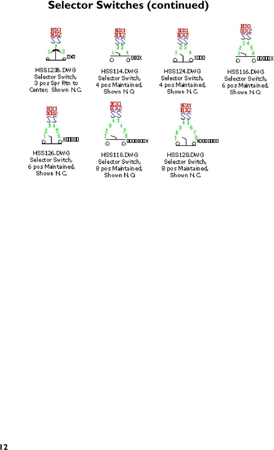
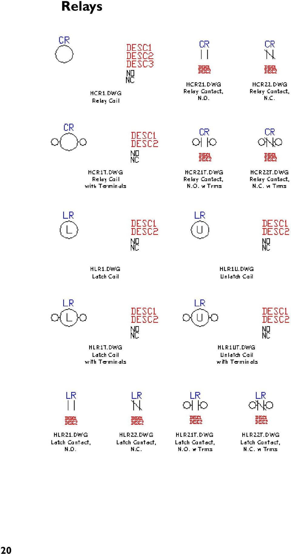
9 Schematic Library Symbols Below is an illustrated listing of the schematic symbols (along with the appropriate block name) supplied with AutoCAD Electrical. The schematic symbols are illustrated here along with the appropriate block name. Push Buttons 9

10 10 Illuminated Push Buttons

11 Selector Switches 11
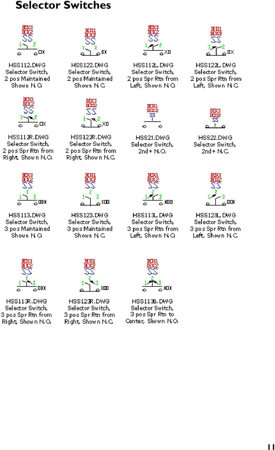
12 12 Selector Switches (continued)
13 Illuminated Selector Switches 13

14 Limit Switches Pressure Switches Temperature Switches 14

15 Flow Switches Level Switches Proximity Switches 15

16 Foot Switches Pull Cord Switches Anti-Plugging Switches 16

17 Toggle Switches 17

18 Photo Eyes Power Distribution Blocks 18

19 Timers 19

20 20 Relays
21 Wire Markers 21
22 22 Terminals
23 Connectors - Wire Number Change 23
24 24 Connectors - Wire Number Change (continued)
25 Connectors - No Wire Number Change 25
26 26 Connectors - No Wire Number Change (continued)
27 Standard Pilot Lights 27
28 Press to Test Pilot Lights Neon Pilot Lights 28
29 Master Test Pilot Lights 29
30 30 Miscellaneous
31 Electronics 31
32 Receptacles Generic Boxes 32
33 Stand-Alone Cross Reference Wire Arrows - Reference Only 33
34 Fuses Disconnect Switches 34
35 Circuit Breakers 35
36 Motor Control Capacitors 36
37 Transformers Solenoids 37
38 38 Instruments
AutoCAD Electrical Fundamentals - NFPA Course Length: 3 days
 AutoCAD Electrical Fundamentals - NFPA Course Length: 3 days The AutoCAD Electrical Fundamentals training course (three days) covers the indispensable core topics for working with the AutoCAD Electrical
Programming A PLC. Standard Instructions
 Programming A PLC STEP 7-Micro/WIN32 is the program software used with the S7-2 PLC to create the PLC operating program. STEP 7 consists of a number of instructions that must be arranged in a logical order
Comparison of NEMA and IEC schematic diagrams
 Cross-Reference MZ081001EN Comparison of NEMA and IEC schematic diagrams General With the increasing emphasis on globalization, many industries are now looking to all parts of the world to produce, market,
Creating Relay Logic Diagrams
 This sample chapter is for review purposes only. Copyright The Goodheart-Willcox Co., Inc. All rights reserved. Creating elay Logic Diagrams Chapter Outline 5. Introduction 5. elay Logic Diagrams 5.3 ules
TRILOGI 5.3 PLC Ladder Diagram Programmer and Simulator. A tutorial prepared for IE 575 by Dr. T.C. Chang. Use On-Line Help
 TRILOGI 5.3 PLC Ladder Diagram Programmer and Simulator A tutorial prepared for IE 575 by Dr. T.C. Chang 1 Use On-Line Help Use on-line help for program editing and TBasic function definitions. 2 Open
How to read this guide
 How to read this guide The following shows the symbols used in this Quick start guide with descriptions and examples. Symbol Description Example P oint Reference Caution [ ] This symbol explains information
2011, The McGraw-Hill Companies, Inc. Chapter 5
 Chapter 5 5.1 Processor Memory Organization The memory structure for a PLC processor consists of several areas, some of these having specific roles. With rack-based memory structures addresses are derived
Autodesk WikiHelp Build your own symbols
 Build your own symbols Procedures You can use the Symbol Builder to create an AutoCAD Electrical symbol or to convert existing non- AutoCAD Electrical symbols. This utility builds an AutoCAD Electrical
Taco Hydronic System Solutions Quick Start Guide
 QUICK START GUIDE Taco Hydronic System Solutions Quick Start Guide Contents Help Resources...3 Introduction...4 Taco Hydronic System Solutions Work Screen Introduction...5 The basics...6 Getting Started
Get wired. AutoCAD. Electrical
 Get wired. AutoCAD Electrical The AutoCAD Electrical Advantage To succeed in today s global marketplace, electrical controls designers can no longer afford to rely on generic software applications to get
PUSH BUTTON START INSTALLATION MANUAL
 PUSH BUTTON START INSTALLATION MANUAL ALTHOUGH THIS PRODUCT HAS BEEN THOROUGHLY TESTED KPIERSON TECHNOLOGIES ASSUMES NO RESPONSIBILITY FOR ANY DAMAGE THAT MAY RESULT BY THE INSTALLATION OF THIS PRODUCT.
Chapter 5. Components, Symbols, and Circuitry of Air-Conditioning Wiring Diagrams
 Chapter 5 Components, Symbols, and Circuitry of Air-Conditioning Wiring Diagrams Objectives Upon completion of this course, you will be able to: Explain what electrical loads are and their general purpose
TUTORIAL 4 Building a Navigation Bar with Fireworks
 TUTORIAL 4 Building a Navigation Bar with Fireworks This tutorial shows you how to build a Macromedia Fireworks MX 2004 navigation bar that you can use on multiple pages of your website. A navigation bar
Introduction to LogixPro - Lab
 Programmable Logic and Automation Controllers Industrial Control Systems I Introduction to LogixPro - Lab Purpose This is a self-paced lab that will introduce the student to the LogixPro PLC Simulator
Electrical Symbols and Line Diagrams
 Electrical Symbols and Line Diagrams Chapter 3 Material taken from Chapter 3 of One-Line Diagrams One-line diagram a diagram that uses single lines and graphic symbols to indicate the path and components
LADDER LOGIC/ FLOWCHART PROGRAMMING DIFFERENCES AND EXAMPLES
 page 1/10 This document is designed as a quick-start primer to assist industrial automation programmers who are familiar with PLCs and Relay Ladder Logic programming to better understand the corresponding
 Control Technology Corporation CTC Monitor User Guide Doc. No. MAN-1030A Copyright 2001 Control Technology Corporation All Rights Reserved Printed in USA The information in this document is subject to
Programming Timers CHAPTER 4-1 GOALS AND OBJECTIVES 4-2 MECHANICAL TIMING RELAYS
 CHAPTER 4 4-1 GOALS AND OBJECTIVES There are two principal goals of this chapter. The first goal is to provide the student with information on the operation and functions of hardware timers both mechanical
Trimble R8 Base and Rover Quick Setup Guide. Inland GPS Inc.
 Trimble R8 Base and Rover Quick Setup Guide Inland GPS Inc. Setting up the GPS Base Equipment Hardware First Find the best, most advantageous secure place to setup the GPS base equipment. Look for a high
TABLE OF CONTENTS. INTRODUCTION... 5 Advance Concrete... 5 Where to find information?... 6 INSTALLATION... 7 STARTING ADVANCE CONCRETE...
 Starting Guide TABLE OF CONTENTS INTRODUCTION... 5 Advance Concrete... 5 Where to find information?... 6 INSTALLATION... 7 STARTING ADVANCE CONCRETE... 7 ADVANCE CONCRETE USER INTERFACE... 7 Other important
ELECTRICAL Designer the solution for electrical engineering, design, hydraulics & pneumatics
 ELECTRICAL Designer the solution for electrical engineering, design, hydraulics & pneumatics Benefits Easy to learn & use, ensuring a rapid return on investment Increased productivity and supporting documentation
Building an Auto-Start Rotary Three Phase Converter. by: Matt Isserstedt
 Building an Auto-Start Rotary Three Phase Converter by: Matt Isserstedt Disclaimer: Electrical wiring is inherently dangerous. No warranties are issued or implied about the safety or success of this system.
PCB Design with Altium: Schematic Entry, Libraries, and Designing Components
 PCB Design with Altium: Schematic Entry, Libraries, and Designing Components Alex Fosdick Capstone Senior Design Instructor: Tom Brown Edited: Jan 30th 2011 Description: This document is the first of two
TIMING, COUNTING, AND DATA-HANDLING INSTRUCTIONS. Key Points
 M O D U L E F O U R TIMING, 4 COUNTING, AND DATA-HANDLING INSTRUCTIONS Key Points This module is a further exploration of the MicroLogix s programming instructions. Module 3 covered basic relay instructions,
Abstract. For notes detailing the changes in each release, see the MySQL for Excel Release Notes. For legal information, see the Legal Notices.
 MySQL for Excel Abstract This is the MySQL for Excel Reference Manual. It documents MySQL for Excel 1.3 through 1.3.6. Much of the documentation also applies to the previous 1.2 series. For notes detailing
Recognizing and understanding schematic symbols will enable you to comprehend a circuit s function.
 Schematic symbols are used to identify and graphically depict the function of fluid power components. Recognizing and understanding schematic symbols will enable you to comprehend a circuit s function.
Module 1: Getting Started With Altium Designer
 Module 1: Getting Started With Altium Designer Module 1: Getting Started With Altium Designer 1.1 Introduction to Altium Designer... 1-1 1.1.1 The Altium Designer Integration Platform...1-1 1.2 The Altium
98371000 REV. REL 1302 WEST BEARDSLEY AVENUE P.O. BOX 1127 ELKHART IN 46515 (574) 295-8330 FAX (574) 293-9914 2011 ELKHART BRASS MFG. CO., INC.
 295-8330 FAX (574) 293-9914 2011 ELKHART BRASS MFG. CO., INC.") 81471067 Electric Monitor Motor Control Panel For use with Model 8394059 SPIT-FIRE Monitor Installation, Operation, and Maintenance Instructions FOR ATEX APPLICATIONS 1302 WEST BEARDSLEY AVENUE P.O. BOX
81471067 Electric Monitor Motor Control Panel For use with Model 8394059 SPIT-FIRE Monitor Installation, Operation, and Maintenance Instructions FOR ATEX APPLICATIONS 1302 WEST BEARDSLEY AVENUE P.O. BOX
Manual Password Depot Server 8
 Manual Password Depot Server 8 Table of Contents Introduction 4 Installation and running 6 Installation as Windows service or as Windows application... 6 Control Panel... 6 Control Panel 8 Control Panel...
MT-350 SMS. Operation Manual. PORTech Communications Inc.
 MT-350 SMS Operation Manual PORTech Communications Inc. Index 1.Hardware Setup...1 2.Software Setup...1 3.Operation Guide...2 4.How to send out a short message...3 5.Report File...6 6.Q & A...6 MT-350
Bank Account 1 September 2015
 Chapter 8 Training Notes Bank Account 1 September 2015 BANK ACCOUNTS Bank Accounts, or Bank Records, are typically setup in PrintBoss after the application is installed and provide options to work with
Chapter 23: Drafting in Worksheet View
 Chapter 23: Drafting in Worksheet View Worksheet View is a powerful, 2D production drafting module. Here you can find all of the drawing and editing tools needed to create fast, accurate, detailed working
INSTALLATION MANUAL XM3 Reader
 INSTALLATION MANUAL XM3 Reader Conditions Transactions, deliveries et cetera will be according to the general terms of delivery as deposited at the Chamber of Commerce at Meppel, The Netherlands. Registration
INTRODUCTION INSTALLING THE SCSI CARD 2940UW PRO
 2940UWPro-ig.qxd 12/21/98 9:55 AM Page 1 INTRODUCTION With the SCSI Card 2940UW Pro, you can connect up to 15 SCSI devices to any IBM-compatible computer with PCI expansion slots. This installation guide
Recording Supervisor Manual Presence Software
 Presence Software Version 9.2 Date: 09/2014 2 Contents... 3 1. Introduction... 4 2. Installation and configuration... 5 3. Presence Recording architectures Operating modes... 5 Integrated... with Presence
Making Basic Measurements. Publication Number 16700-97020 August 2001. Training Kit for the Agilent Technologies 16700-Series Logic Analysis System
 Making Basic Measurements Publication Number 16700-97020 August 2001 Training Kit for the Agilent Technologies 16700-Series Logic Analysis System Making Basic Measurements: a self-paced training guide
How To Create A View Frame In 3D
 12/4/2008-10:00 am - 11:30 am Room:Palazzo O-P (5th) The Secrets of Cutting Plan and Profile Sheets in AutoCAD Civil 3D Michelle Rasmussen - Application Engineer, IMAGINiT Technologies CV304-1P In this
Fireworks 3 Animation and Rollovers
 Fireworks 3 Animation and Rollovers What is Fireworks Fireworks is Web graphics program designed by Macromedia. It enables users to create any sort of graphics as well as to import GIF, JPEG, PNG photos
3BASIC RELAY INSTRUCTIONS
 M O D U L E T H R E E 3BASIC RELAY INSTRUCTIONS Key Points So far, you have learned about the components of the MicroLogix 1000 PLC, including the CPU, the memory system, the power supply, and the input/output
KiCad Step by Step Tutorial
 KiCad Step by Step Tutorial Copyright 2006 David Jahshan: kicad at iridec.com.au 2011 Update Copyright 2011 Phil Hutchinson Copyright: Please freely copy and distribute (sell or give away) this document
Component, Model and Library Concepts. Components - the Basic Building Blocks. Modified by on 2-Jul-2014
 Component, Model and Library Concepts Modified by on 2-Jul-2014 This article explains Altium Designer components, models and libraries, and their relationships. Approaches for identifying and managing
Lesson 1 - Creating a Project
 Lesson 1 - Creating a Project The goals for this lesson are: Create a project A project is a collection entity for an HDL design under specification or test. Projects ease interaction with the tool and
Troubleshooting Guide for Jacks Down LED Lights
 Troubleshooting Guide for Jacks Down LED Lights Equalizer Systems Auto-Level systems manufactured after 2005 feature a pressure switch system that monitors the retracted state of leveling jacks and any
How to set up a database in Microsoft Access
 Contents Contents... 1 How to set up a database in Microsoft Access... 1 Creating a new database... 3 Enter field names and select data types... 4 Format date fields: how do you want fields with date data
Handout: Word 2010 Tips and Shortcuts
 Word 2010: Tips and Shortcuts Table of Contents EXPORT A CUSTOMIZED QUICK ACCESS TOOLBAR... 2 IMPORT A CUSTOMIZED QUICK ACCESS TOOLBAR... 2 USE THE FORMAT PAINTER... 3 REPEAT THE LAST ACTION... 3 SHOW
SIS-PM / SiS-PM-841 / SIS-PMS User Manual. Table of contents
 Silver Shield Power Manager Silver Shield Power Manager 841 Silver Shield Power Manager S (With built-in power supply unit) 2 Table of contents 1. Introduction and features of the SiS-PM/SiS-PM-841/SiS-PMS
AXIS 1440 Print Server For EPSON Printers: Product Update. Important Information for Windows
 Important Information for Windows AXIS 1440 Print Server For EPSON Printers: Product Update Important Information for Windows If you are using Windows 95, Windows 98, or Windows NT 4.0, you need to turn
The corresponding control ladder program is shown at below: The content of element comment will be built is shown below
 Introduction This tutorial explains how to build an application by using the Winproladder programming package to write a ladder control program. In this tutorial we will not tackle the advanced features
PRODUCTIVITY THROUGH INNOVATION 600 CONTROL DIRECT DRIVE TECHNICAL/OPERATION MANUAL
 Rev. D PRODUCTIVITY THROUGH INNOVATION 600 CONTROL DIRECT DRIVE TECHNICAL/OPERATION MANUAL 10 BORIGHT AVENUE, KENILWORTH NEW JERSEY 07033 TELEPHONE: 800-524-0273 FAX: 908-686-9317 TABLE OF CONTENTS Page
WHAT S NEW IN WORD 2010 & HOW TO CUSTOMIZE IT
 WHAT S NEW IN WORD 2010 & HOW TO CUSTOMIZE IT The Ribbon... 2 Default Tabs... 2 Contextual Tabs... 2 Minimizing and Restoring the Ribbon... 3 Customizing the Ribbon... 3 A New Graphic Interface... 5 Live
Tutorials. If you have any questions, comments, or suggestions about these lessons, don't hesitate to contact us at [email protected].
 Tutorials The lesson schedules for these tutorials were installed when you installed Milestones Professional 2010. They can be accessed under File Open a File Lesson Chart. If you have any questions, comments,
Keep it Simple Timing
 Keep it Simple Timing Support... 1 Introduction... 2 Turn On and Go... 3 Start Clock for Orienteering... 3 Pre Start Clock for Orienteering... 3 Real Time / Finish Clock... 3 Timer Clock... 4 Configuring
Using Microsoft Word. Working With Objects
 Using Microsoft Word Many Word documents will require elements that were created in programs other than Word, such as the picture to the right. Nontext elements in a document are referred to as Objects
Welcome to icue! Version 4
 Welcome to icue! Version 4 icue is a fully configurable teleprompter for ipad. icue can be used with an external monitor, controlled by remote and can easily share files in a variety of fashions. 1 of
I ntroduction. Accessing Microsoft PowerPoint. Anatomy of a PowerPoint Window
 Accessing Microsoft PowerPoint To access Microsoft PowerPoint from your home computer, you will probably either use the Start menu to select the program or double-click on an icon on the Desktop. To open
2 Wire Electronic Time Delay Switch. 2 Wire Slave Switch. 3 Wire Electronic Time Delay Switch
 2 Wire Electronic Time Delay Switch Cat No. DS1 2 Wire Slave Switch Cat No. DSS 3 Wire Electronic Time Delay Switch Cat No. DS2 Installation & Operating Instructions DS1/DSS Instructions for Installation
JustClust User Manual
 JustClust User Manual Contents 1. Installing JustClust 2. Running JustClust 3. Basic Usage of JustClust 3.1. Creating a Network 3.2. Clustering a Network 3.3. Applying a Layout 3.4. Saving and Loading
Promethean Trouble Shooting Tips v 2.0. A quick guide for the most common problems
 Promethean Trouble Shooting Tips v 2.0 A quick guide for the most common problems [Type the abstract of the document here. The abstract is typically a short summary of the contents of the document. Type
PM1122 INT DIGITAL INTERFACE REMOTE
 PM1122 INT DIGITAL INTERFACE REMOTE PM1122 INT front panel description: 1. Clear wireless remotes knob: push this button for more than 2 seconds to clear the list of all assigned wireless remote settings
ExpertCAD Release Summary March 2010
 Overview ExpertCAD Release Summary March 2010 ExpertCAD 2010 is major release that includes significant enhancements as well as customer requested software modifications and corrections. This release summary
Eventia Log Parsing Editor 1.0 Administration Guide
 Eventia Log Parsing Editor 1.0 Administration Guide Revised: November 28, 2007 In This Document Overview page 2 Installation and Supported Platforms page 4 Menus and Main Window page 5 Creating Parsing
Advanced Programming with LEGO NXT MindStorms
 Advanced Programming with LEGO NXT MindStorms Presented by Tom Bickford Executive Director Maine Robotics Advanced topics in MindStorms Loops Switches Nested Loops and Switches Data Wires Program view
Michelin North America
 www.centecinc.com SC Telephone: 864.527.7750 Outside SC: 800.227.0855 Michelin North America Industrial Maintenance Technical Interview Outline Industrial Maintenance Technical Interview Outline The Technical
ABB Drives. User s Manual. Pulse Encoder Interface Module RTAC-01
 ABB Drives User s Manual Pulse Encoder Interface Module RTAC-0 Pulse Encoder Interface Module RTAC-0 User s Manual 3AFE 64486853 REV A EN EFFECTIVE:.5.00 00 ABB Oy. All Rights Reserved. Safety instructions
A This panel lists all the IVR queues you have built so far. This is where you start the creation of a IVR
 IVR The IVR (Interactive Voice Response) feature allows you to automate some or all of your inbound call handling. At its simplest, you can implement an IVR that routes calls to a specific department selected
EPM Performance Suite Profitability Administration & Security Guide
 BusinessObjects XI R2 11.20 EPM Performance Suite Profitability Administration & Security Guide BusinessObjects XI R2 11.20 Windows Patents Trademarks Copyright Third-party Contributors Business Objects
Hypercosm. Studio. www.hypercosm.com
 Hypercosm Studio www.hypercosm.com Hypercosm Studio Guide 3 Revision: November 2005 Copyright 2005 Hypercosm LLC All rights reserved. Hypercosm, OMAR, Hypercosm 3D Player, and Hypercosm Studio are trademarks
MAC-821SC-E. Centralized On-Off Remote Controller. English ÏÏËÓÈÎ. Русский [FOR INSTALLER] INSTALLATION MANUAL
![MAC-821SC-E. Centralized On-Off Remote Controller. English ÏÏËÓÈÎ. Русский [FOR INSTALLER] INSTALLATION MANUAL](/thumbs/24/3019861.jpg "MAC-821SC-E. Centralized On-Off Remote Controller. English ÏÏËÓÈÎ. Русский [FOR INSTALLER] INSTALLATION MANUAL") Centralized On-Off Remote Controller MC-821SC-E [FOR INSTLLER] INSTLLTION MNUL English [ [ π À À π ] E XEIPI IO O H IøN E KT T H [ [MONTÖR Ç N] MONTJ ELK TBI ÏÏËÓÈÎ [ДЛЯ УСТАНОВИТЕЛЯ] РУКОВОДСТВО ПО УСТАНОВКЕ
Centralized On-Off Remote Controller MC-821SC-E [FOR INSTLLER] INSTLLTION MNUL English [ [ π À À π ] E XEIPI IO O H IøN E KT T H [ [MONTÖR Ç N] MONTJ ELK TBI ÏÏËÓÈÎ [ДЛЯ УСТАНОВИТЕЛЯ] РУКОВОДСТВО ПО УСТАНОВКЕ
SECTION 13XXX CONTROL DESCRIPTION (DICP Models 02-412NC, 412, 622, 826, 1030)
") PART 1 - GENERAL SECTION 13XXX CONTROL DESCRIPTION (DICP Models 02-412NC, 412, 622, 826, 1030) 1.01 SUMMARY This section describes the operation and control of a drip irrigation system. The major components
PART 1 - GENERAL SECTION 13XXX CONTROL DESCRIPTION (DICP Models 02-412NC, 412, 622, 826, 1030) 1.01 SUMMARY This section describes the operation and control of a drip irrigation system. The major components
Objectives: Part 1: Build a simple power supply. CS99S Laboratory 1
 CS99S Laboratory 1 Objectives: 1. Become familiar with the breadboard 2. Build a logic power supply 3. Use switches to make 1s and 0s 4. Use LEDs to observe 1s and 0s 5. Make a simple oscillator 6. Use
Rako Lighting Driver. For use with: Driver software written and provided by:
 Rako Lighting Driver For use with: Driver software written and provided by: Introduction This document is a guide to integrating a Rako Lighting system with an RTI control system, via a Rako Ethernet bridge.
Executive Summary. Table of Contents
 Executive Summary How to Create a Printed Circuit Board (PCB) Department of Electrical & Computer Engineering Michigan State University Prepared by: John Kelley Revision: 4/06/00 This application note
TYPING IN ARABIC (WINDOWS XP)
") TYPING IN ARABIC (WINDOWS XP) There are two steps involved in setting up your Windows XP computer for Arabic. You must first install support for right-to-left languages; then you must enable Arabic input.
TYPING IN ARABIC (WINDOWS XP) There are two steps involved in setting up your Windows XP computer for Arabic. You must first install support for right-to-left languages; then you must enable Arabic input.
Form Builder Manual. A brief overview of your website s Form Builder with screenshots.
 A brief overview of your website s with screenshots. 1 Table of Contents:...1...3 Creating a New Web Form...4 Editing a Form Element...7 Creating a Form Action...9 Adding a Form Layout to an Action...11
Microsoft Word 2010. Revising Word Documents Using Markup Tools
 Microsoft Word 2010 Revising Word Documents Using Markup Tools Preface Word provides several markup tools that make document collaboration easy. Color coding, highlighting, and the ability maintain multiple
How To Run A Factory I/O On A Microsoft Gpu 2.5 (Sdk) On A Computer Or Microsoft Powerbook 2.3 (Powerpoint) On An Android Computer Or Macbook 2 (Powerstation) On
 On A Computer Or Microsoft Powerbook 2.3 (Powerpoint) On An Android Computer Or Macbook 2 (Powerstation) On") User Guide November 19, 2014 Contents 3 Welcome 3 What Is FACTORY I/O 3 How Does It Work 4 I/O Drivers: Connecting To External Technologies 5 System Requirements 6 Run Mode And Edit Mode 7 Controls 8 Cameras
User Guide November 19, 2014 Contents 3 Welcome 3 What Is FACTORY I/O 3 How Does It Work 4 I/O Drivers: Connecting To External Technologies 5 System Requirements 6 Run Mode And Edit Mode 7 Controls 8 Cameras
PROGRAMMABLE LOGIC CONTROLLERS Unit code: A/601/1625 QCF level: 4 Credit value: 15 OUTCOME 3 PART 1
 UNIT 22: PROGRAMMABLE LOGIC CONTROLLERS Unit code: A/601/1625 QCF level: 4 Credit value: 15 OUTCOME 3 PART 1 This work covers part of outcome 3 of the Edexcel standard module: Outcome 3 is the most demanding
PROGRAMMABLE LOGIC CONTROLLERS Unit code: A/601/1625 QCF level: 4 Credit value: 15
 UNIT 22: PROGRAMMABLE LOGIC CONTROLLERS Unit code: A/601/1625 QCF level: 4 Credit value: 15 ASSIGNMENT 3 DESIGN AND OPERATIONAL CHARACTERISTICS NAME: I agree to the assessment as contained in this assignment.
Introduction to Microsoft Word 2008
 1. Launch Microsoft Word icon in Applications > Microsoft Office 2008 (or on the Dock). 2. When the Project Gallery opens, view some of the available Word templates by clicking to expand the Groups, and
Fig 3. PLC Relay Output
 1. Function of a PLC PLC Basics A PLC is a microprocessor-based controller with multiple inputs and outputs. It uses a programmable memory to store instructions and carry out functions to control machines
Microsoft Excel 2013 Tutorial
 Microsoft Excel 2013 Tutorial TABLE OF CONTENTS 1. Getting Started Pg. 3 2. Creating A New Document Pg. 3 3. Saving Your Document Pg. 4 4. Toolbars Pg. 4 5. Formatting Pg. 6 Working With Cells Pg. 6 Changing
Creating Hyperlinks & Buttons InDesign CS6
 Creating Hyperlinks & Buttons Adobe DPS, InDesign CS6 1 Creating Hyperlinks & Buttons InDesign CS6 Hyperlinks panel overview You can create hyperlinks so that when you export to Adobe PDF or SWF in InDesign,
Content Author's Reference and Cookbook
 Sitecore CMS 6.5 Content Author's Reference and Cookbook Rev. 110621 Sitecore CMS 6.5 Content Author's Reference and Cookbook A Conceptual Overview and Practical Guide to Using Sitecore Table of Contents
Scientific Graphing in Excel 2010
 Scientific Graphing in Excel 2010 When you start Excel, you will see the screen below. Various parts of the display are labelled in red, with arrows, to define the terms used in the remainder of this overview.
Xcode Project Management Guide. (Legacy)
") Xcode Project Management Guide (Legacy) Contents Introduction 10 Organization of This Document 10 See Also 11 Part I: Project Organization 12 Overview of an Xcode Project 13 Components of an Xcode Project
Xcode Project Management Guide (Legacy) Contents Introduction 10 Organization of This Document 10 See Also 11 Part I: Project Organization 12 Overview of an Xcode Project 13 Components of an Xcode Project
PROGRAMMABLE LOGIC CONTROL
 PROGRAMMABLE LOGIC CONTROL James Vernon: control systems principles.co.uk ABSTRACT: This is one of a series of white papers on systems modelling, analysis and control, prepared by Control Systems Principles.co.uk
Operating Systems. and Windows
 Operating Systems and Windows What is an Operating System? The most important program that runs on your computer. It manages all other programs on the machine. Every PC has to have one to run other applications
Windows 8.1 Update 1 Supplement
 Illustrated Series Guide to Windows 8.1 Update 1 Changes June 2014 Table of Contents (CTRL+Click a link to navigate directly to Part 1, 2, 3, or 4.) Part 1: What Version of Windows Am I Using? Part 2:
EDGE FX Network configuration
 Page 1 of 16 TITLE: Category: EDGE FX Network configuration GERBER EDGE Document Number: 4280 Supplied by: Gerber Service Last Modified: April 14, 2011 Summary: In order to connect an EDGE FX to your PC
Layouts, Plotting, Printing
 Layouts, Plotting, Printing Sacramento City College Engineering Design Technology Layouts, Plotting, Printing 1 Objectives Print and plot a drawing. Set up layouts using title blocks and viewports. Create
Introduction. - Please be sure to read and understand Precautions and Introductions in CX-Simulator Operation Manual and
 Introduction - Please be sure to read and understand Precautions and Introductions in CX-Simulator Operation Manual and CX-Programmer Operation Manual before using the product. - This guide describes the
SoftChalk. Level 1. University Information Technology Services. Training, SoftChalk Level Outreach, 1 Learning Technologies and Video Production
 SoftChalk Level 1 University Information Technology Services Training, SoftChalk Level Outreach, 1 Learning Technologies and Video Production Page 1 of 49 Copyright 2013 KSU Department of University Information
Creating tables of contents and figures in Word 2013
 Creating tables of contents and figures in Word 2013 Information Services Creating tables of contents and figures in Word 2013 This note shows you how to create a table of contents or a table of figures
Content Builder: How-To Guide
 Content Builder: How-To Guide In-Line Editing Several of the components have in-line editing where you can format the text and include hyperlinks. To access the in-line editing, click the pencil button
Radio Control System
 Radio Control System The Radio Control System consists of the control transmitter unit held by the operator and the receiver with its associated components in the robot. The Radio Control Transmitter converts
Electronically Controlled Air Suspension (ECAS) for Trucks
 for Trucks") $2.50 Electronically Controlled Air Suspension (ECAS) for Trucks Maintenance Manual No. 36 Issued 7-99 ECAS System for 6 x 2 and 6 x 4 Vehicles with Rear Air Suspensions Service Notes Service Notes This
$2.50 Electronically Controlled Air Suspension (ECAS) for Trucks Maintenance Manual No. 36 Issued 7-99 ECAS System for 6 x 2 and 6 x 4 Vehicles with Rear Air Suspensions Service Notes Service Notes This
RACEAIR REMOTE PAGER SYSTEM
 Computech Systems, Inc. 301-884-5712 30071 Business Center Dr. Charlotte Hall, MD 20622 RACEAIR REMOTE PAGER SYSTEM TM Introduction: Computech s RaceAir Remote Competition Weather Station with the Data
Table of Contents. Introduction... 1 Technical Support... 1
 E-commerce Table of Contents Introduction... 1 Technical Support... 1 Introduction... 1 Getting Started... 2 Data Synchronization... 2 General Website Settings... 2 Customer Groups Settings... 3 New Accounts
ENET-710. ENET-710 - Ethernet Module ENET-710 JAN / 06 FOUNDATION
 ENET-710 ENET-710 - Ethernet Module JAN / 06 ENET-710 FOUNDATION E N E T 7 1 0 ME smar www.smar.com Specifications and information are subject to change without notice. Up-to-date address information is