2011, The McGraw-Hill Companies, Inc. Chapter 5
|
|
|
- Pierce Phelps
- 7 years ago
- Views:
Transcription
1 Chapter 5
2 5.1 Processor Memory Organization

3 The memory structure for a PLC processor consists of several areas, some of these having specific roles. With rack-based memory structures addresses are derived using the rack number, the I/O module slot number and the screw terminal number where the I/O device is wired. With tag-based memory structures all data are assigned a variable name called a tag. A program can be developed using only tag names but you must assign input and output terminals to input and output tags before the program can be executed


4 The memory space can be divided into two broad categories: program files and Data files. Program and Data file organization for the SLC 500 controller.

5 Program files are the areas of processor memory where ladder logic programming is stored. Program files are the part of the processor memory that stores the user ladder logic program. The program accounts for most of the total memory of a given PLC system.


6 The Data file portion of the processor s memory stores input and output status, processor status, the status of various bits, and numerical data. These files are organized by the type of data they contain.

7 I/O address format for the SLC family of PLCs.


8 Simulated I/O addressing format for the SLC family of PLCs.

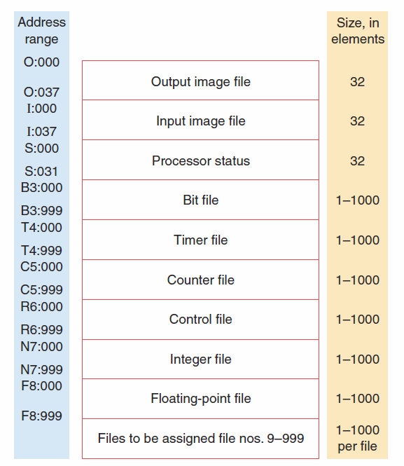
9 Memory organization for a PLC-5 controller.
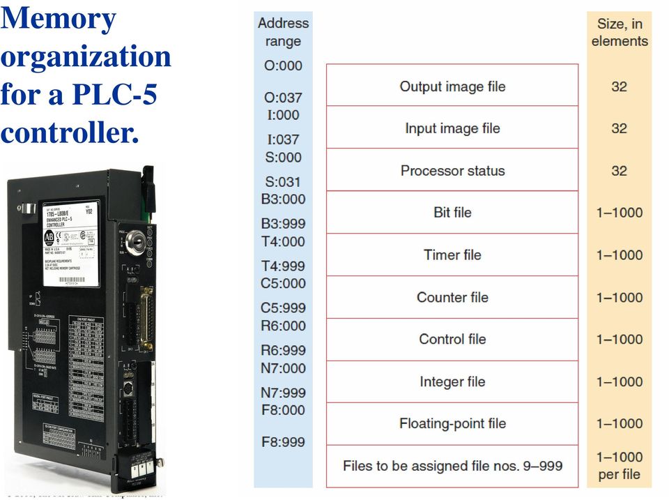

10 The PLC-5 and SLC 500 store all data in global data tables and are based on 16-bit operations. You access these data by specifying the address of the data you want. The addresses in the output data file and the input data file are potential locations for I/O modules mounted in the chassis.

11 The status data file contains information about the processor status The bit data file stores bit status and frequently serves for storage when using internal outputs.

12 The timer file stores the timer status and timer data. The counter file stores the counter status and counter data.


13 The integer file stores integer data values. The floating point file can store data that requires a decimal point.

14 The input image table is allocated to storing the on/off status of connected discrete inputs. If the input is on (switch closed), its corresponding bit in the table is set to 1. If the input is off (switch open), the corresponding bit is cleared, or reset to 0.

15 Simulated operation of the input image table on/off status of connected discrete inputs.


16 The output image table is allocated to storing the on/off status of connected discrete outputs. If the program calls for an output to be ON, its corresponding bit in the table is set to 1. If the program calls for an output to be OFF, its corresponding bit in the table is set to 0.


17 Simulated operation of the output image table on/off status of connected discrete outputs.


18 Typically, micro PLCs have a fixed number of inputs and outputs. This controller has 20 discrete inputs with addresses I/0 through I/19 and 12 discrete outputs with addresses O/1 through O/11.

19 5.2 Program Scan


20 During each program scan cycle, the processor reads all the inputs, takes these values, and energizes or de-energizes the outputs according to the user program.

21 The time it takes to complete a scan cycle is a measure of how fast the controller can react to changes in inputs. If a controller has to react to an input signal that changes states twice during the scan time, it is possible that the PLC will never be able to detect this change.

22 The scan time is a function of: The speed of the processor module The length of the ladder program The type of instructions executed The actual ladder true/false conditions The PLC computes the scan time each time the END instruction is executed. Typical scan time data include the maximum scan time and the last scan time.

23 Overview of the data flow during the scan process.

24 Scan process applied to a single rung program.

25 Scan process applied to a multiple rung program.
26 Vertical versus horizontal scan patterns.
27 5.3 PLC Programming Languages

28 PLC programming language refers to the method by which the user communicates information to the PLC. Standard PLC programming languages
29 Ladder diagram language is the most commonly used PLC language and is designed to mimic hardwired relay logic. Hardwired relay control circuit Equivalent ladder diagram program

30 Instruction list programming language consists of a series of instructions that refer to the basic AND, OR, and NOT logic gate functions. Hardwired relay control circuit Equivalent instruction list program

31 Functional block diagram programming uses instructions that are programmed as blocks wired together to accomplish certain functions.
32 Ladder diagram and functional block diagram programming used to produce the same logical output. Ladder diagram Equivalent function block diagram.
33 Sequential function chart programming language is similar to a flowchart of your process. The program is split into steps with multiple operations happening in parallel branches.

34 Structured text is a high level language primarily used to implement more complex procedures. Ladder diagram Equivalent structured text program.
35 5.4 Relay Type Instructions
36 The ladder diagram language is a symbolic set of instructions used to create the controller program. Representations of contacts and coils are the basic symbols of the logic ladder diagram instruction set.

37 The Examine If Closed (XIC) instruction looks and operates like a normally open relay contact. Associated with each XIC instruction is a memory bit linked to the status of an input device or an internal logical condition in a rung.
38 The memory bit is set to 1 or 0 depending on the status of the input. A 1 corresponds to a true status or on condition. If the instruction memory bit is a 1 (true) this instruction will allow rung continuity through itself, like a closed relay contact.
39 A 0 corresponds to a false status or off condition. If the instruction memory bit is a 0 (false) this instruction will not allow rung continuity through itself and will assume a normally open state just like an open relay contact.
40 Simulated Examine If Closed (XIC) instruction operation.
41 The Examine If Open (XIO) instruction looks and operates like a normally closed relay contact. This instruction asks the PLC s processor to examine if the contact is open. It does this by examining the bit at the memory location specified by the address for a 0 or 1.
42 As with any other input the memory bit is set to 1 or 0 depending on the status of the input. A 1 corresponds to a true status or on condition. The instruction is interpreted as false when the bit is 1 and will not allow rung continuity through itself.
43 A 0 corresponds to a off condition. The instruction is interpreted as true when the bit is 0 and will not allow rung continuity through itself.
 instruction")
44 Simulated Examine If Open (XIO) instruction operation.
45 The Output Energize (OTE) instruction looks and operates like a relay coil. This instruction signals the PLC to energize (switch on) or de-energize (switch off ) the output. The instruction is associated with a memory bit that energizes the output when set to 1 and de-energizes the output when reset to 0.
46 OTE instruction is set to 1 to energize the output. A true logic path is established by the input instructions in the rung.
47 Simulated Output Energize (OTE) instruction operation.
 true; a signal absent makes the NO bit (0)")
48 Action of the field device and PLC bit. A signal present makes the NO bit (1) true; a signal absent makes the NO bit (0) false. The reverse is true for an NC bit.

49 Simulated operation of the field input device and the PLC bit.
50 The main function of the ladder logic diagram program is to control outputs based on input conditions. Each contact or coil symbol is referenced with an address that identifies what is being evaluated and what is being controlled. The same contact instruction can be used throughout the program whenever that condition needs to be evaluated.
51 For an output to be activated or energized, at least one left-to-right true logical path must exist. A complete closed path is referred to as having logical continuity. When logical continuity exists in at least one path, the rung condition and Output Energize instruction are said to be true.

52 Simulated operation of logic continuity.
53 5.5 Instruction Addressing

54 To complete the entry of a relay-type instruction, you must assign an address to each instruction. Address indicates what input is connected to what input device Address indicates what output is connected to what output device

55 Simulated operation of instruction addressing.
56 The assignment of an I/O address can be included in the I/O connection diagram. Inputs and outputs are typically represented by squares and diamonds, respectively.
57 5.6 Branch Instructions
58 Branch instructions are used to create parallel paths of input condition instructions. The rung will be true if either instruction A or B is true.

59 Simulated branch instructions.
60 Parallel branches can be used to allow more than one combination of input conditions. Either A and not B, or C provides logical continuity and energizes output D.
61 Simulated program, either A and not B, or C provides logical continuity and energizes output D.
62 Output branching allows a true logic path to control multiple outputs Either A or B provides a true logical path to all three output instructions: C, D, and E. Additional input instructions can be programmed in the output branches.

63 Simulated program, either A or B provides a true logical path to all three output instructions: C, D, and E.
64 Input and output branches can be nested to avoid redundant instructions and to speed up processor scan time. A nested branch starts or ends within another branch.
65 In some PLC models, the programming of a nested branch cannot be done directly. It is possible, however, to program a logically equivalent branching condition.
66 There may be limitations to the number of series contact instructions that can be included in one rung of a ladder diagram as well as limitations to the number of parallel branches.

67 The PLC will not allow for programming of vertical contacts. Reprogrammed to eliminate vertical contact.
68 The processor examines the ladder logic rung for logic continuity from left to right. If programmed as shown, contact combination FDBC would be ignored. Reprogrammed circuit.
69 5.7 Internal Relay Instructions

70 An internal output does not directly control an output field device. The advantage of using internal outputs is that there are many situations in which an output instruction is required in a program but no physical connection to a field device is needed.

71 SLC 500 controllers use bit file B3 for internal bit addressing.
72 Internal relay used for a program that requires more series contacts than the rung allows. This PLC allows for only 7 series contacts when 12 are actually required for the programmed logic.

73 Simulated internal relay program.
74 5.8 Programming Examine If Closed and Examine If Open Instructions
75 Examine If Closed (XIC) instruction Both the NO and the NC pushbuttons are represented in the program by the Examine If Closed instruction. The normal state of the field input device (NO or NC) does not matter to the controller. What matters is that contacts need to closed to energize the output.
")
76 Simulated Examine If Closed (XIC) instruction
77 Examine If Open (XIO) instruction The pushbutton is represented in the user program by an Examine If Open instruction. This is because the rung must be true when the external pushbutton is open and false when the pushbutton is closed.
")
78 Simulated Examine If Open (XIO) instruction

79 The logic states (0 or 1) indicate whether an instruction is true or false and is the basis of controller operation.

80 The time aspect relates to the repeated scans of the program, wherein the input table is updated with the most current status bits.
81 5.9 Entering The Ladder Diagram


82 Allen-Bradley s RSLogix software packages are windows programming packages used to develop ladder logic programs. Software, in various versions, can be used to program the PLC-5, SLC 500, ControlLogix, and MicroLogic family of processors. A personal computer is most often used and is adapted to the particular PLC model through the use of the relevant programmable controller software.
83 RSLogix SLC 500 main window.

84 Instruction toolbar with bit instructions selected. To place an instruction on a rung, click its icon on the toolbar and simply drag the instruction straight off the toolbar onto the rung of the ladder.
85 The programming software needs to know what processor is being used in conjunction with the user program. The Select Processor Type screen contains a list of the different processors that the RSLogix software can program.

86 The I/O Configuration screen lets you double click or drag-and-drop a module from an allinclusive list to assign it to a slot in your configuration.

87 Data File screens contain data that are used in conjunction with ladder program instructions and include input and output files as well as timer, counter, integer, and bit files. The bit file B3 is used for internal relays.
88 Relay ladder logic is a graphical programming language designed to closely represent the appearance of a wired relay system. The logic is apparent from the highlighting which identifies the logic state of contacts in real time and which rungs have logic continuity.
89 5.10 Modes Of Operation

90 A processor has basically two modes of operation: the program mode and some variation of the run mode. A three-position keyswitch may be used to select different processor modes of operation.
91 The program mode is used to enter a new program, edit or update an existing program, upload files and download files. The run mode is used to execute the user program. The test mode is used to operate or monitor the user program without energizing any outputs. The remote position allows the PLC to be remotely changed between program and run mode by a personal computer connected to the PLC processor.
Programmable Logic Controllers
 Programmable Logic Controllers PLC Addressing and Basic Instructions Dr. D. J. Jackson Lecture 3-1 Basic addressing For the Allen-Bradley PLCs and the simulator used, the input and output image areas (in
Programming A PLC. Standard Instructions
 Programming A PLC STEP 7-Micro/WIN32 is the program software used with the S7-2 PLC to create the PLC operating program. STEP 7 consists of a number of instructions that must be arranged in a logical order
Introduction to LogixPro - Lab
 Programmable Logic and Automation Controllers Industrial Control Systems I Introduction to LogixPro - Lab Purpose This is a self-paced lab that will introduce the student to the LogixPro PLC Simulator
3BASIC RELAY INSTRUCTIONS
 M O D U L E T H R E E 3BASIC RELAY INSTRUCTIONS Key Points So far, you have learned about the components of the MicroLogix 1000 PLC, including the CPU, the memory system, the power supply, and the input/output
Programmable Logic Controllers
 Programmable Logic Controllers PLC Basics Dr. D. J. Jackson Lecture 2-1 Operating systems and application programs A PLC contains a basic operating system that allows for: Downloading and executing user
Programming Logic controllers
 Programming Logic controllers Programmable Logic Controller (PLC) is a microprocessor based system that uses programmable memory to store instructions and implement functions such as logic, sequencing,
2011, The McGraw-Hill Companies, Inc. Chapter 9
 Chapter 9 9.1 Master Control Reset Instruction Program control instructions are used to enable or disable a block of logic program or to move execution of a program from one place to another place. Program
Electrical Symbols and Line Diagrams
 Electrical Symbols and Line Diagrams Chapter 3 Material taken from Chapter 3 of One-Line Diagrams One-line diagram a diagram that uses single lines and graphic symbols to indicate the path and components
TIMING, COUNTING, AND DATA-HANDLING INSTRUCTIONS. Key Points
 M O D U L E F O U R TIMING, 4 COUNTING, AND DATA-HANDLING INSTRUCTIONS Key Points This module is a further exploration of the MicroLogix s programming instructions. Module 3 covered basic relay instructions,
Programming Timers CHAPTER 4-1 GOALS AND OBJECTIVES 4-2 MECHANICAL TIMING RELAYS
 CHAPTER 4 4-1 GOALS AND OBJECTIVES There are two principal goals of this chapter. The first goal is to provide the student with information on the operation and functions of hardware timers both mechanical
SHORT TRAINING COURSES
 Post Office Box SR 95, Spintex Road, Ghana Tel: +233 302 812680, Fax: +233 302 814709 E mail: contact@automationghana.com Website: www.automationghana.com SHORT TRAINING COURSES Equipping industries with
Programmable Logic Controllers Definition. Programmable Logic Controllers History
 Definition A digitally operated electronic apparatus which uses a programmable memory for the internal storage of instructions for implementing specific functions such as logic, sequencing, timing, counting,
LADDER LOGIC/ FLOWCHART PROGRAMMING DIFFERENCES AND EXAMPLES
 page 1/10 This document is designed as a quick-start primer to assist industrial automation programmers who are familiar with PLCs and Relay Ladder Logic programming to better understand the corresponding
TRILOGI 5.3 PLC Ladder Diagram Programmer and Simulator. A tutorial prepared for IE 575 by Dr. T.C. Chang. Use On-Line Help
 TRILOGI 5.3 PLC Ladder Diagram Programmer and Simulator A tutorial prepared for IE 575 by Dr. T.C. Chang 1 Use On-Line Help Use on-line help for program editing and TBasic function definitions. 2 Open
Using Ladder Logic Instructions to Communicate with an Ethernet IP Nexus Unit
 Communicating to an AMCI Ethernet IP Nexus unit is typically accomplished by using a scanner module in the PLC rack. However, it is also possible to communicate with these units directly using instructions
(Cat. No. 1775-L3) Product Data
 Product Data") (Cat. No. 1775-L3) Product Data When it comes to programmable controllers, the more power you can put into a chassis slot, the more control potential you have. The PLC-3 programmable controller, already
(Cat. No. 1775-L3) Product Data When it comes to programmable controllers, the more power you can put into a chassis slot, the more control potential you have. The PLC-3 programmable controller, already
STEP 7 MICRO/WIN TUTORIAL. Step-1: How to open Step 7 Micro/WIN
 STEP 7 MICRO/WIN TUTORIAL Step7 Micro/WIN makes programming of S7-200 easier. Programming of S7-200 by using Step 7 Micro/WIN will be introduced in a simple example. Inputs will be defined as IX.X, outputs
Creating Relay Logic Diagrams
 This sample chapter is for review purposes only. Copyright The Goodheart-Willcox Co., Inc. All rights reserved. Creating elay Logic Diagrams Chapter Outline 5. Introduction 5. elay Logic Diagrams 5.3 ules
PLC SW and Programming. Nagy István, BMF BGK MEI
 PLC SW and Programming Introduction: In the PLCs is usually running 2 Programs: Basic Software: what is the operating system User Program what is the code of instructions written by programators. The PLC
EXPERIMENT 2 TRAFFIC LIGHT CONTROL SYSTEM FOR AN INTERSECTION USING S7-300 PLC
 YEDITEPE UNIVERSITY ENGINEERING & ARCHITECTURE FACULTY INDUSTRIAL ELECTRONICS LABORATORY EE 432 INDUSTRIAL ELECTRONICS EXPERIMENT 2 TRAFFIC LIGHT CONTROL SYSTEM FOR AN INTERSECTION USING S7-300 PLC Introduction:
QUICK START GUIDE. SG2 Client - Programming Software SG2 Series Programmable Logic Relay
 QUICK START GUIDE SG2 Client - Programming Software SG2 Series Programmable Logic Relay SG2 Client Programming Software T he SG2 Client software is the program editor for the SG2 Series Programmable Logic
PROGRAMMABLE LOGIC CONTROL
 PROGRAMMABLE LOGIC CONTROL James Vernon: control systems principles.co.uk ABSTRACT: This is one of a series of white papers on systems modelling, analysis and control, prepared by Control Systems Principles.co.uk
ControlLogix Remote I/O Communication Module
 User Manual ControlLogix Remote I/O Communication Module Catalog Number 1756-RIO Important User Information Solid-state equipment has operational characteristics differing from those of electromechanical
Fig 3. PLC Relay Output
 1. Function of a PLC PLC Basics A PLC is a microprocessor-based controller with multiple inputs and outputs. It uses a programmable memory to store instructions and carry out functions to control machines
Analog Inputs and Outputs
 Analog Inputs and Outputs PLCs must also work with continuous or analog signals. Typical analog signals are 0-10 VDC or 4-20 ma. Analog signals are used to represent changing values such as speed, temperature,
SIMATIC. S7-1200 Getting started with S7-1200. Preface. Quick review 1. Installation 2. Create a simple latch circuit 3. Complete the user program 4
 Preface S7-1200 SIMATIC S7-1200 Getting Started Quick review 1 Installation 2 Create a simple latch circuit 3 Complete the user program 4 Use a watch table for monitoring 5 11/2009 A5E02486791-01 Legal
How to read this guide
 How to read this guide The following shows the symbols used in this Quick start guide with descriptions and examples. Symbol Description Example P oint Reference Caution [ ] This symbol explains information
PROGRAMMABLE LOGIC CONTROLLERS Unit code: A/601/1625 QCF level: 4 Credit value: 15 OUTCOME 3 PART 1
 UNIT 22: PROGRAMMABLE LOGIC CONTROLLERS Unit code: A/601/1625 QCF level: 4 Credit value: 15 OUTCOME 3 PART 1 This work covers part of outcome 3 of the Edexcel standard module: Outcome 3 is the most demanding
The goal is to program the PLC and HMI to count with the following behaviors:
 PLC and HMI Counting Lab The goal is to program the PLC and HMI to count with the following behaviors: 1. The counting should be started and stopped from buttons on the HMI 2. The direction of the count
2011, The McGraw-Hill Companies, Inc. Chapter 3
 Chapter 3 3.1 Decimal System The radix or base of a number system determines the total number of different symbols or digits used by that system. The decimal system has a base of 10 with the digits 0 through
Export and Importing Tags DirectSoft, KEPDirect, Allen-Bradley, C-more Application Note
 Product Family: C-more Number: AN-EA-003 Subject: Exporting and Importing Tags Date Issued: 3-18-2010 Revision: 2 Export and Importing Tags DirectSoft, KEPDirect, Allen-Bradley, C-more Application Note
Module 1 Overview ControlLogix5000
 Module 1 Overview ControlLogix5000 Module Overview This module takes a fundamental approach to a ControlLogix system. It begins with an overview of the architecture and migrates into an introduction of
The 104 Duke_ACC Machine
 The 104 Duke_ACC Machine The goal of the next two lessons is to design and simulate a simple accumulator-based processor. The specifications for this processor and some of the QuartusII design components
Ladder and Functional Block Programming
 CHPTER 11 Ladder and Functional lock Programming W. olton This (and the following) chapter comes from the book Programmable Logic Controllers by W. olton, ISN: 9780750681124. The first edition of the book
Configuring Allen-Brandly ControlLogix PLC with Moxa MGate 5105-MB-EIP. 1 Application Description... 3. 1.1 Objective... 3 1.2 Goals...
 Moxa MGate 5105-MB-EIP Contents Moxa Technical Support Team support@moxa.com 1 Application Description... 3 1.1 Objective... 3 1.2 Goals... 3 2 System Topology... 3 3 Hardware and Software Requirements...
Building a groov HMI for Allen-Bradley Logix Systems. About groov. Building a groov HMI for Allen-Bradley Logix. A-B Systems and groov
 About groov Opto 22 s groov makes it easy to build and deploy simple, effective operator interfaces for your system. groov is browser-based and uses only Internet standards (HTML5, CSS3, SVG, SSL). That
Programmable Logic Controller PLC
 Programmable Logic Controller PLC UPCO ICAI Departamento de Electrónica y Automática 1 PLC Definition PLC is a user friendly, microprocessor based, specialized computer that carries out control functions
Chapter. Getting Started. In This Chapter...
 Getting Started hapter In This hapter... Introduction... Purpose of this Manual... bout Getting Started... Online Help Files and Other ocumentation... Technical Support... onventions Used... Key Topics
Configuring SMC-Flex for Communications over Remote I/O Network using 20-COMM-R Card This document is intended to be used for reference purposes only.
 Configuring SMC-Flex for Communications over Remote I/O Network using 20-COMM-R Card This document is intended to be used for reference purposes only. Objective: This document is intended to provide an
THE INPUT/OUTPUT SYSTEM. Key Points
 M O D U L E T W O THE 2 INPUT/OUTPUT SYSTEM Key Points In the first module, you learned about the basic architecture and operation of the Allen-Bradley Micrologix 1000, including a brief introduction to
Understanding the IEC61131-3 Programming Languages
 profile Drive & Control Technical Article Understanding the IEC61131-3 Programming Languages It was about 120 years ago when Mark Twain used the phrase more than one way to skin a cat. In the world of
Application Technique. Safety Function: Door Monitoring
 Application Technique Safety Function: Door Monitoring Products: Trojan 5 Interlock Switch, GuardLogix Controller, PowerFlex 525 Drive with Safe Torque-off Safety Rating: CAT. 3, PLd to EN ISO 13849-1:
S7 for Windows S7-300/400
 S7 for Windows S7-300/400 A Programming System for the Siemens S7 300 / 400 PLC s IBHsoftec has an efficient and straight-forward programming system for the Simatic S7-300 and ern controller concept can
ControlNet PLC-5 Hot Backup System
 ControlNet PLC-5 Hot Backup System Cat. No. 1785-CHBM User Manual Important User Information Because of the variety of uses for the products described in this publication, those responsible for the application
Safety Function: Door Monitoring
 Application Technique Safety Function: Door Monitoring Products: Trojan 5 Switch, GuardLogix Controller Safety Rating: CAT. 3, PLd to ISO 13849-1: 2008 Topic Page Important User Information 2 General Safety
Logix5000 Controllers
 Logix5000 Controllers Catalog Numbers 1756 ControlLogix, 1756 GuardLogix, 1768 CompactLogix, 1768 Compact GuardLogix, 1769 CompactLogix, 1789 SoftLogix, PowerFlex with DriveLogix Quick Start Important
11. FLOWCHART BASED DESIGN
 plc flowchart - 11.1 Topics: Describing process control using flowcharts Conversion of flowcharts to ladder logic Objectives: Ba able to describe a process with a flowchart. Be able to convert a flowchart
Programming Manual Catalog Numbers 1756 ControlLogix, 1769 CompactLogix, 1789 SoftLogix, 1794 FlexLogix, PowerFlex 700S with DriveLogix
 Logix5000 Controllers Sequential Function Charts Programming Manual Catalog Numbers 1756 ControlLogix, 1769 CompactLogix, 1789 SoftLogix, 1794 FlexLogix, PowerFlex 700S with DriveLogix Important User Information
101 BASICS SERIES LEARNING MODULE 24: PROGRAMMABLE LOGIC CONTROLLERS (PLCS) Cutler-Hammer
 Cutler-Hammer") 101 BASICS SERIES LEARNING MODULE 24: PROGRAMMABLE LOGIC CONTROLLERS (PLCS) Cutler-Hammer WELCOME Welcome to Module 24, which covers Programmable Logic Controllers, or PLCs. The Programmable Logic Controller
101 BASICS SERIES LEARNING MODULE 24: PROGRAMMABLE LOGIC CONTROLLERS (PLCS) Cutler-Hammer WELCOME Welcome to Module 24, which covers Programmable Logic Controllers, or PLCs. The Programmable Logic Controller
Introduction: Implementation of the MVI56-MCM module for modbus communications:
 Introduction: Implementation of the MVI56-MCM module for modbus communications: Initial configuration of the module should be done using the sample ladder file for the mvi56mcm module. This can be obtained
SECTION 13XXX CONTROL DESCRIPTION (DICP Models 02-412NC, 412, 622, 826, 1030)
") PART 1 - GENERAL SECTION 13XXX CONTROL DESCRIPTION (DICP Models 02-412NC, 412, 622, 826, 1030) 1.01 SUMMARY This section describes the operation and control of a drip irrigation system. The major components
PART 1 - GENERAL SECTION 13XXX CONTROL DESCRIPTION (DICP Models 02-412NC, 412, 622, 826, 1030) 1.01 SUMMARY This section describes the operation and control of a drip irrigation system. The major components
Linear Motion and Assembly Technologies Pneumatics Service. Understanding the IEC61131-3 Programming Languages
 Electric Drives and Controls Hydraulics Linear Motion and Assembly Technologies Pneumatics Service profile Drive & Control Understanding the IEC61131-3 Programming Languages It was about 120 years ago
Technical Training Module ( 30 Days)
") Annexure - I Technical Training Module ( 30 Days) Section 1 : Programmable Logic Controller (PLC) 1. Introduction to Programmable Logic Controller - A Brief History, Need and advantages of PLC, PLC configuration,
Annexure - I Technical Training Module ( 30 Days) Section 1 : Programmable Logic Controller (PLC) 1. Introduction to Programmable Logic Controller - A Brief History, Need and advantages of PLC, PLC configuration,
EDI Distributor Control Interface Wiring and Setup Instructions
 Universal I/O EDI Distributor Control Interface Wiring and Setup Instructions EDI UNIVERSAL I/O INTERFACE MODULE The only interface needed for EDI-V5 controls Network compatible with all older EDI controls
SCADAPack E ISaGRAF 3 User Manual
 SCADAPack E ISaGRAF 3 User Manual 2 SCADAPack E ISaGRAF 3 User Manual Table of Contents Part I ISaGRAF 3 User Manual 3 1 Technical... Support 3 2 Safety... Information 4 3 Preface... 6 4 Overview... 8
Allen-Bradley/Rockwell
 MANUFACTURER DATA SHEET High Speed Counter Manufacturer: Allen-radley/Rockwell Model Number: 1746-HSCE See www.geomartin.com for additional PDF datasheets Martin Part Number: E-014901-03 VendorPartNumber:
Control of Boiler Operation using PLC SCADA
 Control of Boiler Operation using PLC SCADA K. Gowri Shankar Abstract This paper outlines the various stages of operation involved in the conversion of a manually operated boiler towards a fully automated
Industrial Process Controllers
 Unit 50: Industrial Process Controllers Unit code: QCF Level 3: Credit value: 10 Guided learning hours: 60 Aim and purpose Y/600/0339 BTEC Nationals This unit provides learners with an opportunity to gain
for both the Verbatim Gateway and Catalyst Autodialer EtherNet Options
 RSLogix 5000 Configuration for both the Verbatim Gateway and Catalyst Autodialer EtherNet Options Addendum 1.0 Revision History Rev # Description Author/Editor Date 1.0 Original Davey Hudson 05/01/2015
L5354 ControlNet Communications Interface
 L5354 ControlNet Communications Interface Technical Manual HA470733 Issue 2 Copyright SSD Drives Inc 2005 All rights strictly reserved. No part of this document may be stored in a retrieval system, or
EnerVista TM Viewpoint Monitoring v7.10
 EnerVista TM Viewpoint Monitoring v7.10 Guideform Specifications July 7, 2014 Page 1 of 14 1 - Product Overview 1.1 Viewpoint Monitoring Scope EnerVista Viewpoint Monitoring is an easy to setup, powerful
SIEMENS S7-300 www.plc-training.co.uk
 2004 Equinox Training Solutions Ltd 1 FAULT DIAGNOSTICS...3 ACCESSING DIAGNOSTICS BUFFER...5 LINK BETWEEN THE PC AND THE PLC....6 BACKING UP A PROGRAM IN THE PLC....7 ONLINE AND OFFLINE...ERROR! BOOKMARK
Analog Input Module Cat. No. 1771 IFE User Manual
 User Manual Because of the variety of uses for the products described in this publication, those responsible for the application and use of this control equipment must satisfy themselves that all necessary
QuickPanel Control DeviceNet Master Communications Card (IC754DVNM01) Quick Start Guide. Thursday September 20, 2007
 Quick Start Guide. Thursday September 20, 2007") QuickPanel Control DeviceNet Master Communications Card (IC754DVNM01) Quick Start Guide Thursday September 20, 2007 Introduction: This document is a brief introduction to the configuration of the QuickPanel
QuickPanel Control DeviceNet Master Communications Card (IC754DVNM01) Quick Start Guide Thursday September 20, 2007 Introduction: This document is a brief introduction to the configuration of the QuickPanel
Chapter 2 Logic Gates and Introduction to Computer Architecture
 Chapter 2 Logic Gates and Introduction to Computer Architecture 2.1 Introduction The basic components of an Integrated Circuit (IC) is logic gates which made of transistors, in digital system there are
Introduction. - Please be sure to read and understand Precautions and Introductions in CX-Simulator Operation Manual and
 Introduction - Please be sure to read and understand Precautions and Introductions in CX-Simulator Operation Manual and CX-Programmer Operation Manual before using the product. - This guide describes the
FLEX I/O Isolated Analog Modules
 FLEX I/O Isolated Analog Modules 1794-IF4I, -OF4I, IF2XOF2I, -IF4IXT, -IF4ICFXT, -OF4IXT, IF2XOF2IXT User Manual Important User Information Solid state equipment has operational characteristics differing
Automating with STEP7 in LAD and FBD
 bisk Automating with STEP7 in LAD and FBD Programmable Controllers SIMATIC S7-300/400 by Hans Berger Publicis MCD Verlag Contents Indroduction 19 1 SIMATIC S7-300/400 Programmable Controller... 20 1.1
ECIO40P ECIO28P ECRM40. Page 1. USB programmable microcontrollers. 0.6 DIP footprint. Supplied with a free version of Flowcode. E-blocks compatible
 Page 1 USB programmable microcontrollers 0.6 DIP footprint Supplied with a free version of Flowcode E-blocks compatible ECIO40P ECIO28P ECRM40 trademarks of. Page 2 What does it do? ECIO devices are powerful
EZ-ZONE RMA & EtherNet/IP Configuration & Startup Using an Allen-Bradley CompactLogix PLC EtherNet/IP Fundamentals
 EtherNet/IP Fundamentals EtherNet/IP is built on the Common Industrial Protocol (CIP) at a foundational level. When communicating using CIP there are two ways to communicate to/from the Master and Slave
Modbus RTU Communications RX/WX and MRX/MWX
 15 Modbus RTU Communications RX/WX and MRX/MWX In This Chapter.... Network Slave Operation Network Master Operation: RX / WX Network Master Operation: DL06 MRX / MWX 5 2 D0 Modbus Network Slave Operation
PROGRAMMABLE LOGIC CONTROLLERS Unit code: A/601/1625 QCF level: 4 Credit value: 15 TUTORIAL OUTCOME 2 Part 1
 UNIT 22: PROGRAMMABLE LOGIC CONTROLLERS Unit code: A/601/1625 QCF level: 4 Credit value: 15 TUTORIAL OUTCOME 2 Part 1 This work covers part of outcome 2 of the Edexcel standard module. The material is
Chapter 8: Ladder Logic Language Reference
 Chapter 8: Ladder Logic Language Reference I. Ladder Logic Fundamentals: Contacts, Coils, Timers and Counters 1. Contacts Ladder logic programs mimic the electrical circuit diagrams used for wiring control
GENERATOR START CONTROL MODULE - MINI (2 Wire to 3 Wire)
") FEATURES & APPLICATIONS Inexpensive 2 wire to 3 wire start controller for electric start high speed gas generators. Optimized for use with Outback Invertors. Supports three types of 3 wire generator control
FEATURES & APPLICATIONS Inexpensive 2 wire to 3 wire start controller for electric start high speed gas generators. Optimized for use with Outback Invertors. Supports three types of 3 wire generator control
Bristol ControlWave Redundant Control
 October 19, 2007 - Page 1 Bristol ControlWave Redundant Control Redundant systems are offered for critical processes and harsh applications that require maximum operational readiness and system availability.
2 SYSTEM DESCRIPTION TECHNIQUES
 2 SYSTEM DESCRIPTION TECHNIQUES 2.1 INTRODUCTION Graphical representation of any process is always better and more meaningful than its representation in words. Moreover, it is very difficult to arrange
Accessing EtherNet/IP Network Variables in a WAGO 750-841 with a ControlLogix PLC Application note
 Accessing EtherNet/IP Network Variables in a WAGO 750-841 with a ControlLogix PLC, English Version 1.0.0 2 General Copyright 2002 by WAGO Kontakttechnik GmbH All rights reserved. WAGO Kontakttechnik GmbH
Part Number 129777-01 Revision A, January 1996. 3500 Monitoring System Rack Configuration and Utilities Guide
 Part Number 129777-01 Revision A, January 1996 3500 Monitoring System Rack Configuration and Utilities Guide Copyright 1995 Bently Nevada Corporation All Rights Reserved. No part of this publication may
Modbus and ION Technology
 70072-0104-14 TECHNICAL 06/2009 Modbus and ION Technology Modicon Modbus is a communications protocol widely used in process control industries such as manufacturing. PowerLogic ION meters are compatible
PLCs and SCADA Systems
 Hands-On Programmable Logic Controllers and Supervisory Control / Data Acquisition Course Description This extensive course covers the essentials of SCADA and PLC systems, which are often used in close
Straton and Zenon for Advantech ADAM-5550. Copalp integrates the straton runtime into the ADAM-5550 device from Advantech
 Straton and Zenon for Advantech ADAM-5550 Copalp integrates the straton runtime into the ADAM-5550 device from Advantech Project Introduction: Programmable Application Controllers (PAC) are powerful and
PLC Based Liquid Filling and Mixing
 PLC Based Liquid Filling and Mixing 1 Mihir Panchal, 2 Aashish Panaskar. 3 Prof. Lalit Kumar KJ College of Engineering and Management Research, Pune, India Abstract: The objective of this paper is to design,
Ethernet/IP Explicit Messaging Using Unity Software
 Data Bulletin 8000DB1025 07/2010 Raleigh, NC, USA Ethernet/IP Explicit Messaging Using Unity Software Retain for future use. Overview Presumption Requirements This data bulletin illustrates how to setup
Digital Systems Based on Principles and Applications of Electrical Engineering/Rizzoni (McGraw Hill
 Digital Systems Based on Principles and Applications of Electrical Engineering/Rizzoni (McGraw Hill Objectives: Analyze the operation of sequential logic circuits. Understand the operation of digital counters.
PLC Support Software at Jefferson Lab
 PLC Support Software at Jefferson Lab Presented by P. Chevtsov ( chevtsov@jlab.org ) - PLC introduction - PLCs at Jefferson Lab - New PLC support software - Conclusions Electromagnetic Relay Encyclopedia
2 Basic Ladder Logic Programming
 2 asic Ladder Logic Programming Chapter Topics: asic ladder logic symbols Ladder logic diagram Ladder logic evaluati Cverting relay logic to ladder logic OJECTIVES Up completi of this chapter, you will
Application Note Profinet Modules
 BusWorks XT Series XT1xx3-000 I/O Models for Profinet 10/100MB Industrial Ethernet I/O Modules Application Note Profinet Modules Communicating with Acromag Model XTxxx3-000 Profinet I/O Modules From a
Automating witfi STEP7 in LAD and FBD
 Automating witfi STEP7 in LAD and FBD Programmable Controllers SIMATIC S7-300/400 by Hans Berger 2nd revised edition, 2001 Publicis MCD Corporate Publishing Contents Contents Indroduction 19 1 SIMATIC
Logix5000 Controllers Nonvolatile Memory Card
 Programming Manual Logix5000 Controllers Nonvolatile Memory Card Catalog Numbers 1756 ControlLogix, 1756 GuardLogix, 1768 CompactLogix, 1768 Compact GuardLogix, 1769 CompactLogix, 1789 SoftLogix, PowerFlex
Candle Plant process automation based on ABB 800xA Distributed Control Systems
 Candle Plant process automation based on ABB 800xA Distributed Control Systems Yousef Iskandarani and Karina Nohammer Department of Engineering University of Agder Jon Lilletuns vei 9, 4879 Grimstad Norway
Training document for the company-wide automation solution Totally Integrated Automation (T I A) MODULE A5. PLC-Simulation with S7-PLCSIM
 MODULE A5. PLC-Simulation with S7-PLCSIM") Training document for the company-wide automation solution Totally Integrated Automation (T I A) MODULE A5 PLC- Simulation with S7-PLCSIM T I A Training document Page 1 of 14 Module A5 This document was
Training document for the company-wide automation solution Totally Integrated Automation (T I A) MODULE A5 PLC- Simulation with S7-PLCSIM T I A Training document Page 1 of 14 Module A5 This document was
The following shows the symbols used in this Quick start guide with descriptions and examples. Symbol Description Example. Select [Project] [New].
![The following shows the symbols used in this Quick start guide with descriptions and examples. Symbol Description Example. Select [Project] [New].](/thumbs/39/18407968.jpg "The following shows the symbols used in this Quick start guide with descriptions and examples. Symbol Description Example. Select [Project] [New].") How to read this guide The following shows the symbols used in this Quick start guide with descriptions and examples. Symbol Description Example P oint Caution This symbol explains information you need
How to read this guide The following shows the symbols used in this Quick start guide with descriptions and examples. Symbol Description Example P oint Caution This symbol explains information you need
PLC Programming for Industrial Automation. Kevin Collins
 PLC Programming for Industrial Automation Kevin Collins Contents Introduction PLC Basics Function of a PLC Inputs and Outputs PLC Architecture and Wiring Diagrams Network Protocols Questions Ladder Programming
Programmable Logic Controllers Basic Level Textbook TP 301
 Programmable Logic Controllers Basic Level Textbook TP 301 Festo Didactic 093311 en B-II Authorised applications and liability The Learning System for Automation and Technology has been developed and prepared
8.1 The Structure and Features of Programmable Logic Controller
 Chapter 8 : Programmable Logic Controller (PLC) 8.1 The Structure and Features of Programmable Logic Controller Programmable logic controllers (PLCs) have been used in industry in one form or another for
Programming software the Windows based solution for Modicon Micro/Compact/ Quantum/Momentum/584/984
 Programming software the Windows based solution for Modicon Micro/Compact/ Quantum/Momentum/584/984 We do more with electricity 2 If you are like other loyal Modicon PLC owners, chances are you have a
First Steps with CoDeSys. Last update: 05.03.2004
 Last update: 05.03.2004 CONTENT 1 STARTING CODESYS 3 2 WRITING THE FIRST PROGRAM 3 3 A VISUALIZATION FOR THIS 7 4 START THE TARGET SYSTEM 9 5 SETTINGS FOR ESTABLISHING THE CONNECTION 9 6 START THE PROJECT
ZEN-SOFT01-V3. Cat.No.W386-E1-03
 ZEN-SOFT01-V3 Cat.No.W386-E1-03 ZEN-SOFT01-V3 ZEN Support Software Operation Manual Revised April 2003 iv Notice: OMRON products are manufactured for use according to proper procedures by a qualified operator
IPX AUTOMATIC IP NETWORK LOSS BACKUP A/B SWITCH INSTRUCTION BOOK IB6444-02
 IPX AUTOMATIC IP NETWORK LOSS BACKUP A/B SWITCH INSTRUCTION BOOK IB6444-02 TABLE OF CONTENTS DESCRIPTION 2 MOUNTING INSTRUCTIONS 2 HOW TO CABLE THE IPX 2/3 POWER SUPPLY INSTALLATION 3 OPERATION 3 CARE