Programming Timers CHAPTER 4-1 GOALS AND OBJECTIVES 4-2 MECHANICAL TIMING RELAYS
|
|
|
- Eileen Little
- 7 years ago
- Views:
Transcription
1 CHAPTER GOALS AND OBJECTIVES There are two principal goals of this chapter. The first goal is to provide the student with information on the operation and functions of hardware timers both mechanical and electronic. The second goal is to show how the programmable timer instructions are applied in Allen-Bradley PLCs that are used in industrial automation systems. After completing this chapter you should be able to: Describe the operation of a mechanical timing relay. Explain the differences between timed contacts and instantaneous contacts of a timing relay. Describe the difference between mechanical and electronic timing relays. Compare and contrast retentive timers to non-retentive timers. Describe the operation of TON, TOF, and RTO timer instructions. Describe the operation of cascading timers. Develop ladder logic solutions using timer instructions for the Allen-Bradley PLC 5, SLC 500, and ControlLogix series of PLCs. Convert relay ladder logic timer rungs to their PLC equivalent. Troubleshoot system problems associated with I/O modules and ladder rungs with timer instructions. 4-2 MECHANICAL TIMING RELAYS Mechanical timing or time delay relays, as the name implies, have fixed or variable delay incorporated into their design that suspends the movement of the contacts when the coil is energized, de-energized, or both. Timers are a critical part of industrial automation and are necessary in sequential processes where a machine follows a set operational sequence with some steps assigned a specific time span. In relay ladder logic the timers are called timing relays because a contact closure is associated with the timing function. Knowledge of timing relays is important because relay ladder logic implementations continue to be used in small control applications and where higher current levels must be switched. In addition, relay ladder logic program with mechanical timers must be converted to a PLC implementation; as a result, an understanding of mechanical timer operation is necessary for a successful conversion. The schematic symbols for the four basic types of timing relays are illustrated in Figure 4-1. Chapter 4 141

2 FIGURE 4-1: Schematic symbols for timing relays. Description Control International/British Electronic Normally open timed closed NOTC (a) TC or Normally closed timed open NCTO (b) TO or Normally open timed open NOTO (c) TO or Normally closed timed closed NCTC (d) TC or Rehg and Sartori, Industrial Electronics, 1 st Edition, 2006, Reprinted by permission of Pearson Education, Inc., Upper Saddle River, NJ Mechanical timing relays use pneumatics to develop the time delay by the controlled release of air through an orifice during the expansion or compression of a bellows. The time delay period is set by positioning a needle valve to vary the amount of orifice restriction. The pneumatic timing relay provides on-delay and off-delay timing options with a range of 0.05 to 180 seconds and an accuracy of plus or minus 10 percent of the set time. However, pneumatic timers tend to drift over time, thus requiring periodic adjustment. Both AC and DC switching types are available with a typical switching current range of 6 to 12 amps and a voltage range of 120 to 600 volts. The continuous current is typically 10 amps Timed Contacts Timed contacts have a fixed or adjustable delay action set by the pneumatic timing process. Time delay relay contacts are specified as either normally open (NO) or normally closed (NC), with the additional requirement that the delay operates in the direction of closing or in the direction of opening. The four basic types of time delay relay contacts fall into two groups: on delay and off delay. On-delay timing relays. The normally open and normally closed timed contacts for on-delay timing relays have special names. The normally open are called normally open, timed close (NOTC) contacts, and the normally closed are called normally closed, timed open (NCTO) contacts. The two types of contacts operate as follows: Normally open, timed closed (NOTC): The control and electronic symbols and the timing diagram for normally open, timed closed on-delay timing relays are shown in Figures 4-1(a) and 4-2(a), respectively. After the relay coil is energized, the timed normally open (NO) contacts remain open until after the time delay value. After the time delay (5 seconds in the figure), the timed contacts change state (NO contacts close) and remain in that new state as long as the coil is energized. When the coil is de-energized, the timed contacts immediately return to their initial state (NO contacts open). Normally closed, timed open (NCTO): The symbols and timing diagram for normally closed, timed open on-delay time delays are shown in Figures 4-1(b) and 4-2(b), respectively. After the relay coil is energized, the timed normally closed (NC) contacts remain closed until after the time delay value. After 142 Chapter 4

3 the time delay (5 seconds in the figure), the timed contacts change state (NC contacts open) and remain in that new state as long as the coil is energized. When the coil is deenergized, the timed contacts immediately return to their initial state (NC contacts closed). The action of the NOTC and NCTO contacts could also be described as the action of an NO and an NC contact on an on-delay time relay. Off-delay timing relays. The normally open and normally closed timed contacts for off-delay timing relays also have special names. The normally open are called normally open, timed open (NOTO) contacts, and the normally closed are called normally closed, timed closed (NCTC) contacts. The two types of contacts operate as follows: Normally open, timed open (NOTO): The control and electronic symbols and the timing diagram for normally open, timed open off-delay timing relays are shown in Figures 4-1(c) and 4-2(c), respectively. After the relay coil is energized, the timed NO contacts immediately close and remain in that new state as long as the coil is energized. When the coil is de-energized, the timed contacts remain in the changed state (the NO contacts close) until the set time delay value is reached. At the end of the time delay (5 seconds in the figure), the timed contacts return to their initial state (NO contacts open). Note that the delay starts after power is removed from the coil. Normally closed, timed close (NCTC): The symbols and timing diagram for normally closed, timed closed off-delay timing relays are shown in Figures 4-1(d) and 4-2(d), respectively. After the relay coil is energized, the timed NC contacts immediately open and remain in that new state as long as the coil is energized. When the coil is de-energized, the timed contacts remain in the changed state (NC contacts open) until the set time delay value is reached. At the end of the time delay (5 seconds in the figure), timed contacts return to their initial state (NC contacts closed). Note that the delay starts after power is removed from the coil. The action of the NOTO and NCTC contacts could also be described as the action of an NO and an NC contact on an off-delay time relay. In addition to the timed contacts on timing relays, instantaneous contacts are also present Instantaneous Contacts Instantaneous contacts operate independently from the timing process, like standard control relay contacts. When the coil is energized the contacts change states; when the coil is de-energized they return to their normal states. An illustration of the instantaneous contact on each type of delay is provided in Figure 4-2; the schematic symbols are the same as a basic relay contact. Note that the contact state change coincides with the waveform of the coil voltage. EXAMPLE 4-1 Draw the relay ladder diagram for an application where a motor is started 10 seconds after a start momentary push button is depressed and is stopped when a stop momentary push button is depressed. Solution Figure 4-3 illustrates the solution, where TMR1 is the NOTC time delay coil, contact TMR1-1 is an instantaneous contact, and contact TMR1-2 is a timed contact. The instantaneous contact seals in the momentary start push button after it s released, and the normally open, timed closed contact activates the motor after the 10-second delay. Both TMR1 contacts are associated with one timer. Chapter 4 143

4 FIGURE 4-2: Timing relay timing diagrams. On delay (a) NOTC Coil power Off On 5 seconds Close Contact status Open (b) NCTO Coil power Contact status Off Close On 5 seconds Open Close Instantaneous contact Open Off delay (c) NOTO Coil power Off On Close 5 seconds Contact status Open (d) NCTC Coil power Contact status Off On Close Open 5 seconds Close Instantaneous contact Open Rehg and Sartori, Industrial Electronics, 1 st Edition, 2006, Reprinted by permission of Pearson Education, Inc., Upper Saddle River, NJ FIGURE 4-3: Relay ladder diagram for Example 4-1. L1 L2 Start Stop TMR Timing Relay Operation The operation is based on the pneumatic control illustrated in Figure 4-4. Study the drawing until all the components are familiar, and refer to the figure as you read the following description. TMR1-1 TMR1-2 10s M When the solenoid plunger (10) is retracted from the push rod (11), it allows the spring (3) located inside the synthetic rubber bellows (1) to push the timing mechanism plunger (4) upward. As the plunger rises, it causes the over-center toggle mechanism (5) to move the snap-action 144 Chapter 4

5 FIGURE 4-4: Pneumatic timing mechanism. Source: (a) Courtesy of Square D/Schneider Electric and (b) Courtesy of Rockwell Automation, Inc. toggle blade (6) upward, which in turn picks up the push plate (7), which carries the movable contacts (8). The speed with which the bellows can expand is determined by the setting of the needle valve (2). If this needle valve is nearly closed, a maximum length of time will be required for air to pass it and permit the bellows to expand. The needle valve setting determines the time interval that must elapse between the release of the solenoid actuator and expansion of the bellows to switch the contact. When the push rod (11) is again depressed by the solenoid plunger (10), it forces the timing mechanism plunger (4) to the lower position, exhausting the air through the release valve (9) and resetting the timer almost instantaneously Selecting Timing Relays Timing relays are selected based on the following operational characteristics: 4-3 ELECTRONIC TIMING RELAYS Electronic timing relays are more accurate and repeatable than pneumatic timing relays, plus they provide an economical solution for applications requiring basic timing functions. Figure 4-5(a) depicts a typical electronic timing relay, and Figure 4-5(b) depicts a multifunctional timing relay. The typical timing relays provide the timing functions as described in the previous section and operate with a supply voltage in the 24 to 48 VDC range or the 24 to 240 VAC range. The solid-state electronics provide timing settings from 0.05 seconds to 60 hours with a timing accuracy of plus or minus 5 percent of the set time and an excellent repeatability of plus or minus 0.2 percent. The multifunction electronic timing relay is typically microprocessor controlled and provides 10 or more timing functions, which are variations of the on-delay and off-delay timed outputs plus FIGURE 4-5: Timing relays. Length of time delay required Range of timing values required for the machine or process Timing options required for the process Repeatability and accuracy of the timed delay required for the process Current rating, configuration, and quantity of timed contacts and/or instantaneous contacts required for the control (a) Electronic timing relay Courtesy of Rockwell Automation, Inc. (b) Multifunction timing relay Chapter 4 145

6 some pulsed output options. With the variety of timing functions and ranges available, the multifunction relay eliminates the need for additional auxiliary relays in complex applications, saving installation time and reducing parts and labor costs. Go to the Allen-Bradley Web site at and select timers to see the numerous output combinations that are available for electronic timers. These electronic timing relays are stand-alone devices and not a part of a PLC. FIGURE 4-6: PLC timer block. (a) Allen Bradley 4-4 PLC TIMER INSTRUCTIONS T45 K2 Timer instructions are important in PLC applications where the time for a machine s cycle times is critical, or when some time delay is needed between process sequences. PLC timers are output instructions that provide the same functions as on-delay and off-delay mechanical timing relays and electronic time delay relays. PLC timers offer numerous advantages over their mechanical and electronic counterparts. PLC time settings can be easily changed and the quantity of timers can be changed through programming without wiring modifications. In addition, the PLC timer is highly accurate and repeatable because its time delays are generated in the PLC processor. The accuracy of the timed event may be affected, however, if the program has a large number of rungs and therefore a long scan time. 4-5 ALLEN-BRADLEY TIMER INSTRUCTIONS The timer instructions for the Allen-Bradley (AB) PLC 5, SLC 500, and Logix processors operate in nearly identical fashion. Therefore, most of the example solutions in this chapter use the SLC 500 instructions; however, PLC 5 and ControlLogix instructions are used in a few examples to illustrate the differences in the three systems. AB has three timer instructions discussed in this chapter: timer on-delay (TON), timer offdelay (TOF), and retentive timer on-delay (RTO). The next sections prepare for the discussion of these instructions by introducing the timer ladder logic symbol, timer parameters, and the function of the timer Boolean bits and integer registers. (b) Mitsubishi Allen-Bradley Timer Symbol and Parameters All three AB timer instructions are represented as blocks in the ladder logic with three (Control- Logix) or four (PLC 5 and SLC 500) data parameters. Figure 4-6(a) shows the TON timer instructional block for the PLC 5 and SLC 500. In other PLC brands the timer uses a symbol like that in Figure 4-6(b), and in some cases they use the symbol of a timing relay discussed in Section 4-2. Each PLC manufacturer represents the data inside the block slightly differently, but the parameters generally include the same information. The timer blocks for the PLC 5 and SLC 500 are illustrated in Figure 4-7 and the block for the Control- Logix processor is illustrated in Figure 4-8. The four parameters required for a timer include timer number, time base, preset value, and accumulator value. Refer to Figures 4-7 and 4-8 as you read the following descriptions. Timer Number and Tag Name: The Allen- Bradley PLC 5 and SLC 500 timer instructions, Figure 4-7(a) and (b), use a timer file, T4, for all timers and attach a unique number to identify the specific timer. For example, T4:0, T4:1, and T4:2 are three timers numbered 0, 1, and 2. The colon (:) is a delimiter used to separate the file number and the timer number. The number of timers allowed in file T4 is 256 (numbers 0 to 255); if more timers 146 Chapter 4

7 FIGURE 4-7: PLC 5 and SLC 500 TON timer instructions. (a) SLC 500 timer instruction (b) PLC 5 timer instruction (c) Timer date file for SLC 500 and PLC 5 are needed files T10 through T255 can be used, with each holding 256 timers. The timer database file is shown in Figure 4-7(c) with the current value of all parameters displayed for each timer. Timer parameters can be entered directly into the timer instructions or into this database file dialog box. The Logix processors, Figure 4-8(a), use a tag name for the timers, such as Pump_timer. The descriptive tag name makes it easier to know what function the timer serves in the control system. Any valid tag name (see Chapter 3 for tag name rules) can be used, but the name must be declared using the programming software tag properties dialog boxes illustrated in Figure 4-8(b). The tag name typed into the timer instruction appears at the top of the dialog box when the tag is validated. The description (optional), tag type, and data type are added to complete the validation. The description can be any text desired, and the tag type used most often is Base. The data type, TIMER, must be selected or typed. A pop-up Select Data Type dialog box appears when the selection box button at the right of the data type line is double-clicked. The timer tag database is shown in Figure 4-8(c). The database is accessed by doubleclicking the Program Tags file in the file menu. This dialog box offers two views of the timer database: monitor tags or edit tags. To view tag values the monitor tags tab is selected at the lower left of the dialog box and the display in Figure 4-8(c) is displayed. The values for all timer variables are displayed. Note that the Logix system has some additional variables compared to the PLC 5 and SLC 500 Chapter 4 147
, use a tag name for the timers, such as Pump_timer.")
8 FIGURE 4-8: ControlLogix timer instruction. systems. If the other tab, edit tags, is selected then changes to the timer database are entered. Time Base: PLC timers increment from 0 to a preset value in time segments of 1, 0.1, 0.01, and seconds. The time base indicates the incremental change in the accumulator value when the timer instruction is active. For example, if the preset holds 1000 and the time base is 0.01, then the time delay is configured for 10 seconds ( ). Figure 4-7(a) illustrates the time base options for the SLC 500 and Figure 4-7(b) shows the options for the PLC 5. Note that the SLC 500 has a time base value of seconds listed, but it is not supported and cannot be used. The ControlLogix timer, Figure 4-8(a), has two variations from the PLC 5 and SLC 500 models. First, the time base selection field is absent since it has a fixed time base of seconds, and second, the timer number is replaced by a tag name. Preset Value (PRE): This integer value is the number of time increments that the timer must accumulate to reach the desired time 148 Chapter 4
. Figure 4-7(a) illustrates the time base options for the SLC 500 and Figure 4-7(b) shows the options for the PLC 5.")
9 delay. For example, if the time base is 0.01 and the preset value is 200, then the time delay is 2 seconds ( ). The range of preset value for the PLC 5 and SLC 500 timers is from 0 to 32,767. If a timer preset value is a negative number, a runtime error occurs. The preset value for the ControlLogix timer in Figure 4-8(a) and (c) is The timer time is 3 seconds ( ) since the time base is fixed at seconds for each increment of the accumulator. The range for the ControlLogix preset value is 32,768 to 32,767 for integers, but it is in the 2 million range for double integers. Accumulator Value (ACC): The accumulator value indicates the number of increments that the timer has accumulated while the timer rung and instruction are active. The ranges of values permitted for the accumulator are the same as those given for the preset value. The accumulator value is reset to zero when the timer is reset, and the non-retentive timers are reset when the rung and instruction are false. Configuring a timer includes: selecting the timer number or tag name, selecting a time base (SLC 500 and PLC 5 only), and entering a preset value for the time delay required. In rare situations an accumulator value other than zero is entered. The three timer bits used in timer ladder logic control are described next Allen-Bradley Timer Bits The three AB timer models (PLC 5, SLC 500, and Logix) and all three Allen Bradley timer types have the same three Boolean bits for ladder logic control. Their names and descriptions follow. Timer Enable Bit (EN): The enable bit is true when the rung input logic is true, and the enable bit is false when the rung input logic is false. When the EN bit is true the timer accumulator is incrementing at the rate set by the timer time base. Timer Timing Bit (TT): The timer timing bit is true only when the accumulator is incrementing. TT remains true until the accumulator reaches the preset value. When the accumulator value is equal to or greater than the preset value, the timer timing bit is returned to a false condition. In other words, the TT bit indicates when timing action is occurring and can be used to control timed events in automation applications. Timer Done Bit (DN): The DN bit signals the end of the timing process by changing states from false to true or from true to false depending on the type of timer instruction used Allen-Bradley TON, TOF, and RTO Instructions The three types of Allen-Bradley timer instructions include: on-delay timer (TON), off-delay timer (TOF), and retentive timer (RTO). The truth tables in Table 4-1 describe the conditions that cause a true or false state on the timer output bits (EN, TT, and DN) for each timer type. This truth table applies to timers from all three Allen-Bradley processors. Read the truth table before continuing. The action of the timer enable bit is the same for all three types; namely, it is true if the timer instruction rung logic is true and false if the logic is false. However, the timer action created by the enable varies with the three different timer types. Review Table 4-1 to verify this operation. The timer timing (TT) bits of TON and RTO are true when the accumulator (ACC) is less than the preset value AND the timer is enabled. The TOF has the same operation except that the enable bit is false. All three of the timers have a different logic requirement for the TT to be false. Also, the done bit on each timer has unique true and false conditions. Review TT and DN bit operation in the table. The most frequently used timer instruction, TON, has an active DN bit if the ACC is equal to or greater than the preset (PRE) value AND the timer enable bit remains true. Compare this with the logic for the other two. The timing diagrams of the TON, TOF, and RTO timers are illustrated in Figure 4-9. Study each timer in the figure and note the condition of the TT and DN bits as the EN bit transitions from false to true and back to false. Compare the operation illustrated in the timing diagram with the description of the output bit operation in Table 4-1. Note the operation of the TT and DN bits if the EN Chapter 4 149

10 TABLE 4-1 Timer output bit truth table. On-delay timer output bits are TRUE if are FALSE if Timer enable Timer rung is true. Timer rung is false. Timer timing Timer rung is true AND the accumulator Timer rung is false OR the value is less than the preset value. accumulator value is equal to or greater than the preset value OR the timer done bit is true. Timer done Timer rung is true AND the accumulator Timer rung is false OR the timer value is equal to or greater than the rung is less than the preset value. preset value. (a) Truth table for the on-delay timer output bits (TON) Off-delay timer output bits are TRUE if are FALSE if Timer enable Timer rung is true. Timer rung is false. Timer timing Timer rung is false AND the accumulator Timer rung is true OR the value is less than the preset value. accumulator is equal to or greater than the preset value OR the done bit is false. Timer done Timer rung is true OR the timer timing Timer rung is false AND the bit is true. accumulator value is equal to or greater than the preset value. (b) Truth table for the off-delay timer output bits (TOF) Retentive timer output bits are TRUE if are FALSE if Timer enable Timer rung is true. Timer rung is false. Timer timing Timer rung is true AND the accumulator Timer rung is false OR the value is less than the preset value. accumulator value is equal to or greater than the preset value. Timer done The accumulator value is equal to or Reset instruction is initiated OR greater than the preset value. the timer rung is true but the accumulator is less than the preset value. (c) Truth table for the retentive timer output bits (RTO) bit changes before the preset value is reached by the accumulator. A summary of the general operation of a TON, TOF, and RTO timer with a 15-second preset value follows. The description applies to timers from all three Allen-Bradley processors. Refer to Table 4-1 and Figure 4-9 as you read each timer s description. On-delay Timer. The on-delay timer (TON) in Figure 4-9(a) starts timing (15 second delay) when the timer s ladder rung becomes true. The true rung forces the enable (EN) bit to true, causes the accumulator to start incrementing by the values set in the time base, and makes the timer timing (TT) bit true. The done 150 Chapter 4

11 FIGURE 4-9: Timing diagrams. Input True False Enable bit Timing bit Done bit True False True False False 7s True Note: When the enable bit was true for only 7 seconds, the done bit remains false since the ACC never equaled the PRE value. 15s (a) On-delay timer timing diagram Input Enable bit Timing bit 5s Note: If the EN bit goes true before the accumulator reaches the preset value, then the timer is reset. Done bit 15s (b) Off-delay timer timing diagram (DN) bit becomes true when the accumulator value reaches the preset time value. The DN bit remains true until the timer s rung returns to the false state, making the EN bit false. This reset action also returns the accumulator to a zero value. The condition of the timer instruction is determined by the input logic on the rung; therefore, timer operation is controlled by the associated input field device(s). If the EN bit returns to a false condition before the accumulator reaches the preset value [the 7 second pulse in Figure 4-9(a)], then the timer is reset and the DN bit remains false (no change). A photocopier is an example of an on-delay timing function. When the print button is pressed, the operation of the photocopier is not started for some time period (an on-delay) to permit the copier to heat up before starting to make copies. Off-delay Timer. For the off-delay timer (TOF) in Figure 4-9(b), the done bit is true and the accumulator is set to zero when the ladder rung and enable bit are true. No changes in the timer bits occur until the ladder rung and enable bit return to the false state in Figure 4-9(b). At this point the accumulator starts incrementing toward the 15 second preset value with the increment set by the time base. When the accumulator value equals the preset value, the timer done bit goes from true to false. If the EN bit returns to a true condition, [the 5 second pulse in Figure 4-9(b)], before the accumulator reaches the preset value, then the timer is reset and the DN bit remains true (no change). As an example of an off-delay timing function, think about the light in an automatic garage door opener. When the garage door opener is activated, the light comes on when the door starts to open. The door motor turns off when it is open, but the light remains on (an off-delay) a preset period of time before it is extinguished. Retentive Timer. The retentive timer, RTO, accumulates time whenever it is active, which means that the timer retains the accumulated Chapter 4 151
 Off-delay timer timing diagram (DN) bit becomes true when the accumulator value reaches the preset time value.")
12 FIGURE 4-9: (Continued). Input Enable bit Preset (11 sec) Accumulator value 0 Accumulator value retained when rung condition is false Timing bit Done bit Reset (c) Retentive timer timing diagram time even if the rung is not active or power to the PLC is lost. As a result, the accumulator retains the current time value and starts incrementing from that value when the ladder rung and enable bit once again go true. The time base sets the time increment for the accumulator change and the preset value indicates the desired time delay. The done bit goes true and the timer timing bit goes false when the accumulator value is equal to or greater than the preset value. The retentive timer retains its current time when power is lost or when the timer rung is false. The only method of resetting a retentive timer is by a reset instruction that has the address as the timer. Figure 4-9(c) illustrates the operation of a retentive timer with a preset value of 11 seconds. When the timer rung becomes active, the enable bit is true and the timer accumulator (ACC) begins to increment. When the rung is false, the ACC holds the current value, which is 4 in the figure. When the input returns to a true state, the ACC begins incrementing from 4 until it reaches the preset value of 11. At the preset value, the ACC stops incrementing and the retentive timer done bit (DN) is true. The figure shows how a reset (RES) instruction is used to reset the ACC to zero and return the timer done bit to a false state. The accumulator of the retentive timer operates like the trip mileage indicator on the instrument panel in your car. As you drive, the indicator displays your accumulated miles. When you stop for gas the display holds the number. It then continues accumulating as you start driving again. When you finish the trip, you manually reset the display to zero. With the operation of the TON, TOF, and RTO timer instruction covered, the next section describes how each timer parameter and bit is addressed. 152 Chapter 4

13 4-6 ALLEN-BRADLEY TIMER PARAMETER AND BIT ADDRESSING The timer parameters and control bits described in the last two sections are stored in the processor memory. The format for storing the PLC 5 and SLC 500 parameters is the same, but is quite different for the Logix family of processors PLC 5 and SLC 500 Timer Memory Map The PLC 5 and SLC 500 processors use three words in memory to store control bit values and operational parameters. Figure 4-10 illustrates how the timer memory for these processors is organized. Each block of words is identified with the timer number; for example, a three-word block would be addressed as T4:5. This threeword block holds the data for timer 5. Word 0 is the control word with the control or timer output bits (EN, TT, and DN) stored in the three most significant bits. These output bits are Boolean data types, so their values in the timer memory map are either 0 or 1. The preset value is stored in word 1 and the accumulator value is stored in word 2. Figure 4-10 illustrates the layout of the three bits (EN, TT, and DN) and two words (PRE and ACC) that can be addressed for system control. The address structure for timers in the PLC 5 and SLC 500 processors uses the following format: Tf:e.s/b Each element in the timer address format is defined in the following table. Element T f Description The T indicates that the address is a timer file. The default value for f is 4. File 4 supports 256 timer instructions (T4:0 to T4:255). If more than 256 timers are needed in a program, then additional files (9 to 255) are available. Each of these files supports 256 timers (T9:0 to T9:255). : Element delimiter e Element number, e, is the number of the timer. For file 4, e has a range of 0 to 255 timers. The same range is used for e if files 9 to 255 are used.. Word delimiter s Word number, S, indicates one of the three The value of S ranges from 0 to 2 timer words. because each timer has three addressable words. / Bit delimiter b Bit number, b, is the bit location in the The range is 0 to 15 for all three timer words. timer words, but bits 13, 14, and 15 are the only ones used for word 0. Example timer data addresses are listed in the following table. Study the timer address structure (Tf:e.s/b) and the description of each address element in the previous table, and then verify that you understand what timer data is being addressed by each of the following examples. Chapter 4 153

14 T4:0/15 or T4:0/EN Enable bit of timer number 0 T4:2/14 or T4:2/TT Timer timing bit of timer number 2 T4:15/13 or T4:15/DN Done bit of timer number 15 T4:5.1 or T4:5.PRE Preset value of timer number 5 T4:10.2 or T4:10.ACC Accumulator value of timer number 10 T4:20.1/0 or T4:20.PRE/0 Bit 0 of the preset value of timer number 20 T4:3.2/11 or T4:3.ACC/11 Bit 11 of the accumulator value of timer number 3 T4:25/DN The done bit for timer 25 in timer file 4 T4:255/TT The timer timing bit for the last timer (255) in timer file 4 T9:0.ACC The accumulator word for timer 0 in timer file 9 T9:255.PRE The preset word for the last timer (255) in timer file 9 T255:255/EN The enable bit for last available timer in the system FIGURE 4-10: Timer output bit image map EN TT DN Timer element Internal use Word 0 Preset value PRE Accumulated value ACC 1 2 Addressable bits EN = Bit 15 enable TT = Bit 14 timer timing DN = Bit 13 done Addressable words PRE = Preset value ACC = Accumulated value Timers are 3-word elements. Word 0 is the control word, word 1 stores the preset value, and word 2 stores the accumulated value. These addressing examples indicate all of the possible addressing modes that are available for PLC 5 and SLC 500 timers. Note that parameters are addressed based on the bit or word number or with the mnemonic for that bit or word. For example, in the first example bit 15 is also the enable (EN) bit. Also, in the fourth example the preset is addressed as a.1 for word 1 or as.pre for preset word. These bit and word addresses are used in any other PLC instruction where a timer bit or word address is permitted. For example, in Chapter 6, move instructions will use the corresponding word addresses which are used with counters to transfer preset values to counters ControlLogix Timer Addressing The format for addressing ControlLogix timers is simplified with the use of tag names for each timer. Figure 4-11 illustrates how the data for timer, running_seconds, is displayed in the Program Tags dialog box. Note that the Edit Tags tab is selected at the bottom of the dialog box, so this box could be used to enter parameter data. The Monitor Tags tab could be selected to examine the value of timer bits and words. The ControlLogix timers have the EN, TT, and DN output bits and PRE and ACC parameter words found in the PLC 5 and SLC 500 PLCs plus the four other data values displayed in Figure Chapter 4

15 FIGURE 4-11: ControlLogix output bit and parameter addressing Timer Contacts versus PLC Instructions An important distinction was made in Chapter 3 between the normally open and normally closed physical contacts on input field devices, and the XIC and XIO instructions used for ladder input logic. This distinction is also carried over to the timers. Mechanical timing relays have physical contacts and electronic timers have either physical contacts or solid-state switches to control output devices. However, the virtual timers in PLCs are created in software; as a result, they have memory bit outputs and the PLC timer is called an instruction. There is, however, a relationship between the mechanical and electronic timers and their PLC counterparts. The PLC TON timer is the same as an on-delay timing relay, and the TOF timer is the same as the off-delay timing relay. The TON done bit is like a normally open, timer closed timing relay contact, and the TOF done bit is like the normally open, timed opened relay contact. The instantaneous contacts on the timing relays are equivalent to the enable bit on both types of PLC timers. 4-7 PROGRAMMING ALLEN-BRADLEY TON AND TOF TIMER LADDER LOGIC Sections 4-5 and 4-6 presented an overview of timer instructions, including setting timing parameters and addressing timer data. This section uses that information to develop timer ladder logic for machine and system control. The first section looks at six ladder configurations that are used to build most timer ladder logic. Learning this standard timer ladder logic is important because most timer ladder solutions are just variations from these six standard ladder configurations. The second half of this section covers a number of example problems that demonstrate how the three Allen-Bradley timer instructions are used for automation control Standard Ladder Logic for Allen-Bradley TON Timers Automation programs that include timers use a standard set of timer ladder logic configurations. Learning these common timer ladder solutions is a great way to start the study of timer applications. The standard TON solutions for common control problems are listed in Figure The first set of standard rungs, Figure 4-12(a) through (d), illustrates timer ladder configurations triggered by field device switches with momentary or continuous types of contacts. This set also covers the different output options for TON timers. Read the description of the timer operation in the figure as you study the standard timer ladder logic. It is clear that the simplest timer applications require two rungs, one for the timer instruction and one for the output device being controlled. In addition, a maintain contact input for the timer is the simplest to implement. The momentary contact inputs Chapter 4 155

16 M04_REHG8818_02_SE_C04.QXD 5/29/08 8:22 PM Page 156 FIGURE 4-12: Standard ladder logic rungs for TON timers. 156 Chapter 4 GRIDLINE SET IN 1ST-PP TO INDICATE SAFE AREA; TO BE REMOVED AFTER 1ST-PP

17 FIGURE 4-12: (Continued). Chapter 4 157
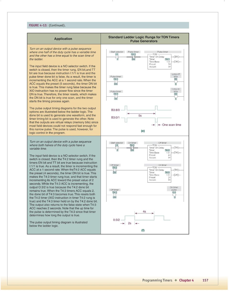
18 requires a sealing instruction because the TON timer instruction must be true until the timer reaches the preset value. The timer s TT bit is used to perform the required sealing of the input. The standard circuits in Figure 4-12(c and d) also demonstrate how a timer is used to turn on an output for a set time period or turn on one after a set time period. The second set, Figure 4-12(e) and (f), features two configurations for using timers to create pulse generators. The pulse generator in Figure 4-12(e) is called a regenerative clock because it uses an output of the timer reset itself. The XIO instruction in the timer rung is addressed with the timer done to reset the timer whenever the done bit changes from false to true. The TON instruction is reset whenever the timer rung is false; as a result, the false done bit resets this regenerative circuit so the timer instruction done bit is true for only one scan time. This output pulse (one scan time wide) is too narrow to drive most field devices, so this ladder configuration is used most often for logic control within the PLC program. This configuration is used in the next two chapters for control of other PLC instructions. The other pulse generator, Figure 4-12(f), provides a variable duty cycle that is a function of the preset values for the two timers. The done bit from the first timer, T4:2, is used to control the output, O:3/2, and to make the second timer, T4:3, active. T4:3 determines how long the output is on before it resets the system and timing sequence is restarted. Therefore, the second timer controls the on time for the pulse and the first timer controls the off time. This is a regenerative timer using two timer instructions. Note that other program rungs can be inserted between the timer rungs and the output rung. Read the description of the pulse generator operation in the figure as you study the standard pulse generator ladder logic. The Allen-Bradley SLC 500 timer is used to create the example solutions in all six TON ladders. However, PLC 5 and ControlLogix timers could be used and the operation of the ladder logic would be unchanged. The only difference would be the addresses used for the input logic for the PLC 5 and the use of tags for the ControlLogix Standard Ladder Logic for Allen- Bradley TOF Timers The standard TOF solutions used in control problems are listed in Figure The standard rungs illustrate how the TOF timer performs with a selector switch for the input field device. The selector contacts, used in Figure 4-13(a), remain in the open position long enough for the timer to time out or complete the timing process. The field device in Figure 4-13(b) could be either a selector with maintain contacts or a push button with momentary contacts. The time duration for a true done bit is the sum of the time the input is held closed and the preset time value. The choice is dictated by the system control requirements. The timing diagrams are included because the operation of TOF timers is often more difficult to understand than their TON counterparts. Note that other program rungs can be inserted between the timer rung and the output rung. Read the description of the timer operation in the figure as you study the standard timer ladder logic. The Allen-Bradley SLC 500 timer is used to create both TOF example solutions; however, PLC 5 and ControlLogix TOF timers could be used and the operation of the ladder logic would be unchanged. The only difference would be the addresses used for the input logic in the PLC 5 and the use of tags for the ControlLogix Allen-Bradley TON and TOF Timer Applicat ions This section includes a number of timer applications and example problems that demonstrate how TON and TOF timers for the three Allen-Bradley processors are used. The applications describe the use of a timer in a control requirement, and the examples show you how a control problem is stated and illustrate one workable solution. In addition, the standard time ladder logic, which is the basis for the solution, is indicated. What becomes clear is that just a few timer configurations are used to solve most of the timer problems in automation control. Pump delay control logic application. In some large pump applications power to the pump motor is delayed while auxiliary circuits open valves or initiate priming operations. The ladder logic in Figures 4-14(a and b) illustrates a pump 158 Chapter 4
 is called a regenerative clock because it uses an output of the timer reset itself.")
19 FIGURE 4-13: Standard ladder logic rungs for TOF timers. start delay timer using a TON PLC timer instruction and the associated timing diagram. When selector A, an input field device switch, is active the timer begins incrementing toward the preset value in 0.01 second increments. Two seconds later, when the preset value is reached ( seconds), the timer done bit becomes active and the pump contactor is turned on. When SS1 is opened, the timer resets and the pump turns off. As in all TON timers, the accumulated value Chapter 4 159

20 FIGURE 4-14: On-delay timer diagrams. is automatically reset to zero when the enable bit goes from a 1 to a 0. Note that this timer example is the standard configuration shown in Figure 4-12(b). All of the timer applications are either one of the standard timer ladder logic configurations or some combination of those configurations. Traffic Light Control Application. Figure 4-15 depicts a ladder diagram where the active and done bits from three on-delay timers are used to turn on and off traffic lights the red light is on for 32 seconds, the green light is on for 27 seconds, and the amber light is on for 5 seconds. Note that the timers are numbered T4:0, T4:1, and T4:2; their preset times are 32, 27, and 5 seconds, respectively. Refer to Figure 4-15 as you read the following operation of the timers. 1. Before power is applied, all timer EN, TT, and DN bits are false, all examine if closed (XIC) instructions (- -) are not active (no continuity), and all examine if open (XIO) instructions (- -) are not active (continuity). 2. At power on the T4:2/DN bit is false, so the examine if open instruction in rung 0 is true, which makes the rung true. Since rung 0 is true, the T4:0/EN bit is true, and the T4:0/TT timing cycle is started. The two input instructions in rung 3 are true (T4:0/EN bit is true and the T4:0/DN false), so output O:2/0 is true and the red light is turned on. 3. After 32 seconds, the T4:0/DN done bit is a 1, making rung 3 and output O:2/0 false. When the address on an examine if open instruction is a 1, the instruction is false 160 Chapter 4

21 FIGURE 4-15: Ladder diagram for traffic light control. and continuity is removed, which turns off the red light. In addition, the T4:0/DN addressed XIC instruction in rung 1 is true, which starts the green light timer. Rung 4 is also true because the T4:1 timer enable bit is true and the T4:1 done bit is false. This makes output O:2/1 active and turns on the green light. 4. After an additional 27 seconds, the T4:1/DN bit goes true, making rung 4 false and extinguishing the green light. In addition, rung 2 is true, which starts the amber timer. As a result, rung 5 and the O:2/2 output are true, thus illuminating the amber light. 5. After an additional 5 seconds, the T4:2 done bit goes true, making rung 5 false and extinguishing the amber light. Also, the true T4:2/DN bit makes rung 0 and the T4:0 timer false. This causes the T4:0 done bit to go false, which makes rung 1 false, causing the T4:1 timer and T4:1/DN bit to go false. The change in T4:1/DN makes rung 2 and T4:2 false. With this change in T4:2 and an active start selector, rung 0 returns to the active state. 6. With rung 0 true again, the previous timing sequence is repeated. All of the timers in this example are modifications of the standard timer ladder logic in Figure 4-12(b). Machine guard lock and indicator application. Production machines often lock out the operator while the machine is processing parts plus a fixed time for the machine to come to a stop. The ladder logic in Figure 4-16(a) uses the selector switch, which starts the process and triggers a TOF timer. The timer controls an output that Chapter 4 161
22 FIGURE 4-16: Off-delay timer diagrams. locks the machine doors at the start of the process and lights a doors locked indicator. The operator turns off the machine when the part is finished and the TOF timer keeps the doors locked for an additional 5 seconds for the motor to come to a stop. Figure 4-16(b) displays the timing diagram for this operation. When the NO selector switch is true, the machine start input instruction is true, the T4:0/EN and T4:0/DN bits are true, the accumulator value is reset to zero, and rung 0 becomes active. As a result, rung 1 is true because T4:0/DN is true and the machine door is locked and the process light is illuminated. When the machine is turned off, the switch contacts return to the NO state, rung 0 returns to the false state, and the timer accumulator begins incrementing toward the preset value while T4:0/DN remains true. When the preset value is reached ( seconds), the timer output (T4:0/DN) becomes false and the door is unlocked and the process light is extinguished. Note that this timer example is the standard configuration in Figure 4-13(b), but it has a maintain contact switch. Compare the ladder logic and the timing diagrams for the TOF timer in Figures 4-13(b) and 4-16 to see how the standard ladder logic was adapted to this application. 162 Chapter 4
23 EXAMPLE 4-2 Draw a ladder diagram for a pumping system where the pump requires a 5-second delay before pumping; when the pump is shut off, it requires a 15-second delay before it can be restarted. Start and stop switches are NO momentary contact push buttons. Solution Refer to Figure 4-17(a), the ladder solution, and 4-17(b), the timing diagram, as you read the following description. The pump control is implemented with T4:0, an on-delay timer, and T4:1, an off-delay timer. The activation of the momentary start switch makes rung 0 true, which initiates the on-delay timer (T4:0/EN and T4:0/TT are true). Since the start switch is FIGURE 4-17: Pumping system ladder diagram for Example 4-2. Chapter 4 163
24 a momentary contact type, the I:1/10 instruction must be sealed with the T4:0 timer timing bit (T4:0/TT) to keep the rung active while the timer is incrementing the accumulator for the on-delay time of 5 seconds. Upon completion of the on-delay time of 5 seconds, the T4:0 timer done bit (T4:0/DN) is active, which makes the XIC instruction in rung 2 true. The XIO instruction in rung 2 is also true (continuity) because the T4:1 timer done bit (T4:0/DN) addressing the XIO instruction is false or 0. As a result, the pump output, O:2/5, is true, so the pump starts 5 seconds after the start switch is pressed. The sealing instruction (O:2/5 around T4:0/DN in rung 2) is necessary because the T4:0/DN bit starts the pump after 5 seconds but is a 1 or true for only one scan. The sealing instruction in rung 2 keeps the pump on after the delayed start. T4:0/DN is true for only one scan because the timer resets immediately after the preset time is reached. This occurs because T4:0/TT bit is used to seal the XIC start instruction in rung 0, which is a momentary start push button. At 5 seconds the timer timing bit becomes false, which makes the T4:0 timer rung false and the timer resets. As a result, one scan after the done bit is true it returns to the false or 0 state. Review the operation of the standard ladder logic in Figure 4-12(c), which is used for this pump delay timer. Now when the stop PB is pressed, the I:1/11 instruction in rung 1 is true, and the T4:1/DN bit of the TOF timer in rung 1 is true. When the stop switch is released, the T4:1 TOF timer starts timing and keeps the T4:1/DN bit true for 15 seconds. Thus the initiation of the stop push button makes the XIO instruction in rung 2 false because the T4:1/DN output is true. This action stops the pump because output O:2/5 false. Rung 2 is held in this false condition by the XIO instruction for the duration of the T4:1 time, so the start push button cannot restart the pump for 15 seconds. Upon completion of the off-delay time of 15 seconds, the T4:1/DN output becomes false, the XIO instructions returns to true state, and the pump can be restarted. Note that this example uses standard timer ladder logic from Figures 4-12(c) and 4-13(b). 4-8 ALLEN-BRADLEY RETENTIVE TIMERS Review the operation of the retentive timer in Table 4-1(c) on page 158 and Figure 4-9(c). The retentive timer (RTO) operates the same as a TON timer, except the accumulator (ACC) is not reset when the timer enable returns to the false state. The accumulator will continue to increment from the previous value whenever the EN bit goes from false to true. When the ACC equals the PRE value the timer timing bit goes false and the done bit becomes true. The done bit remains in that state until a reset (RES) instruction for the timer is executed. The reset instruction is covered in the next section. Compare and study Table 4-1(c) and Figure 4-9(c) until you understand the logical operation of an RTO timer instruction. The RTO instruction operates the same for all three Allen-Bradley processors. The RTO ladder logic symbol for the PLC 5, SLC 500, and ControlLogix systems is the same as their TON symbol. After the reset instruction is introduced in the next section, an example is used to illustrate how the RTO and RES instructions operate Reset Instruction for RTO Timer and Other Allen-Bradley Instructions Since the retentive timer does not automatically reset itself, a reset instruction is used to return the timer accumulator to zero and turn off the done bit. The reset (RES) instruction must have the same program address as the timer you want to reset. The reset instruction can reset the timer at any time during its operation and is independent of the input conditions. The reset instruction is also used for the TON and TOF timers and with other Allen-Bradley instructions covered in later chapters. The operation of the reset instruction is the same for all three types of Allen-Bradley PLC processors. Example 4-3 illustrates the operation of an RTO and RES instruction in an automation system. Heater sequential control application. In large furnaces the electric heaters are often turned on or off in a sequence to control the heating and cooling of the product. In this application three heaters come on at the same time and remain on as long as the momentary start switch is held. When the switch is released the heaters turn off in sequence at 30-second 164 Chapter 4
LADDER LOGIC/ FLOWCHART PROGRAMMING DIFFERENCES AND EXAMPLES
 page 1/10 This document is designed as a quick-start primer to assist industrial automation programmers who are familiar with PLCs and Relay Ladder Logic programming to better understand the corresponding
Programming A PLC. Standard Instructions
 Programming A PLC STEP 7-Micro/WIN32 is the program software used with the S7-2 PLC to create the PLC operating program. STEP 7 consists of a number of instructions that must be arranged in a logical order
2011, The McGraw-Hill Companies, Inc. Chapter 5
 Chapter 5 5.1 Processor Memory Organization The memory structure for a PLC processor consists of several areas, some of these having specific roles. With rack-based memory structures addresses are derived
TIMING, COUNTING, AND DATA-HANDLING INSTRUCTIONS. Key Points
 M O D U L E F O U R TIMING, 4 COUNTING, AND DATA-HANDLING INSTRUCTIONS Key Points This module is a further exploration of the MicroLogix s programming instructions. Module 3 covered basic relay instructions,
3BASIC RELAY INSTRUCTIONS
 M O D U L E T H R E E 3BASIC RELAY INSTRUCTIONS Key Points So far, you have learned about the components of the MicroLogix 1000 PLC, including the CPU, the memory system, the power supply, and the input/output
Fig 3. PLC Relay Output
 1. Function of a PLC PLC Basics A PLC is a microprocessor-based controller with multiple inputs and outputs. It uses a programmable memory to store instructions and carry out functions to control machines
Introduction to LogixPro - Lab
 Programmable Logic and Automation Controllers Industrial Control Systems I Introduction to LogixPro - Lab Purpose This is a self-paced lab that will introduce the student to the LogixPro PLC Simulator
Programming Logic controllers
 Programming Logic controllers Programmable Logic Controller (PLC) is a microprocessor based system that uses programmable memory to store instructions and implement functions such as logic, sequencing,
How to read this guide
 How to read this guide The following shows the symbols used in this Quick start guide with descriptions and examples. Symbol Description Example P oint Reference Caution [ ] This symbol explains information
Electrical Symbols and Line Diagrams
 Electrical Symbols and Line Diagrams Chapter 3 Material taken from Chapter 3 of One-Line Diagrams One-line diagram a diagram that uses single lines and graphic symbols to indicate the path and components
PROGRAMMABLE LOGIC CONTROLLERS Unit code: A/601/1625 QCF level: 4 Credit value: 15 OUTCOME 3 PART 1
 UNIT 22: PROGRAMMABLE LOGIC CONTROLLERS Unit code: A/601/1625 QCF level: 4 Credit value: 15 OUTCOME 3 PART 1 This work covers part of outcome 3 of the Edexcel standard module: Outcome 3 is the most demanding
EXPERIMENT 2 TRAFFIC LIGHT CONTROL SYSTEM FOR AN INTERSECTION USING S7-300 PLC
 YEDITEPE UNIVERSITY ENGINEERING & ARCHITECTURE FACULTY INDUSTRIAL ELECTRONICS LABORATORY EE 432 INDUSTRIAL ELECTRONICS EXPERIMENT 2 TRAFFIC LIGHT CONTROL SYSTEM FOR AN INTERSECTION USING S7-300 PLC Introduction:
11. FLOWCHART BASED DESIGN
 plc flowchart - 11.1 Topics: Describing process control using flowcharts Conversion of flowcharts to ladder logic Objectives: Ba able to describe a process with a flowchart. Be able to convert a flowchart
2011, The McGraw-Hill Companies, Inc. Chapter 9
 Chapter 9 9.1 Master Control Reset Instruction Program control instructions are used to enable or disable a block of logic program or to move execution of a program from one place to another place. Program
Creating Relay Logic Diagrams
 This sample chapter is for review purposes only. Copyright The Goodheart-Willcox Co., Inc. All rights reserved. Creating elay Logic Diagrams Chapter Outline 5. Introduction 5. elay Logic Diagrams 5.3 ules
Programmable Logic Controllers
 Programmable Logic Controllers PLC Addressing and Basic Instructions Dr. D. J. Jackson Lecture 3-1 Basic addressing For the Allen-Bradley PLCs and the simulator used, the input and output image areas (in
Programmable Logic Controllers
 Programmable Logic Controllers PLC Basics Dr. D. J. Jackson Lecture 2-1 Operating systems and application programs A PLC contains a basic operating system that allows for: Downloading and executing user
Analog Inputs and Outputs
 Analog Inputs and Outputs PLCs must also work with continuous or analog signals. Typical analog signals are 0-10 VDC or 4-20 ma. Analog signals are used to represent changing values such as speed, temperature,
TRILOGI 5.3 PLC Ladder Diagram Programmer and Simulator. A tutorial prepared for IE 575 by Dr. T.C. Chang. Use On-Line Help
 TRILOGI 5.3 PLC Ladder Diagram Programmer and Simulator A tutorial prepared for IE 575 by Dr. T.C. Chang 1 Use On-Line Help Use on-line help for program editing and TBasic function definitions. 2 Open
PUSH BUTTON START INSTALLATION MANUAL
 PUSH BUTTON START INSTALLATION MANUAL ALTHOUGH THIS PRODUCT HAS BEEN THOROUGHLY TESTED KPIERSON TECHNOLOGIES ASSUMES NO RESPONSIBILITY FOR ANY DAMAGE THAT MAY RESULT BY THE INSTALLATION OF THIS PRODUCT.
Operational Overview and Controls Guide
 DOCUMENT: ECSEQ2-1 EFFECTIVE: 02/14/07 SUPERSEDES: 02/26/03 Operational Overview and Controls Guide Standard Two or Three Pump Type VFD Booster Controls 6700 Best Friend Road. Norcross, GA 30071. (770)
GENERATOR START CONTROL MODULE - MINI (2 Wire to 3 Wire)
") FEATURES & APPLICATIONS Inexpensive 2 wire to 3 wire start controller for electric start high speed gas generators. Optimized for use with Outback Invertors. Supports three types of 3 wire generator control
FEATURES & APPLICATIONS Inexpensive 2 wire to 3 wire start controller for electric start high speed gas generators. Optimized for use with Outback Invertors. Supports three types of 3 wire generator control
Signature and ISX CM870 Electronics
 Signature and ISX CM870 Electronics Cummins West Training Center System Description General Information The Signature and ISX CM870 engine control system is an electronically operated fuel control system
AUTOMATIC TRANSFER SWITCH CONTROL UNIT OPERATOR S MANUAL
 ATS-220 AUTOMATIC TRANSFER SWITCH CONTROL UNIT OPERATOR S MANUAL For Use in 208 to 240 Volts Single and 3 Phase ATS Systems With 110Volt AC or DC Control Motors and selenoids 4501 NW 27 ave Miami FL 33142
Programmable Logic Controller PLC
 Programmable Logic Controller PLC UPCO ICAI Departamento de Electrónica y Automática 1 PLC Definition PLC is a user friendly, microprocessor based, specialized computer that carries out control functions
Chapter 5. Components, Symbols, and Circuitry of Air-Conditioning Wiring Diagrams
 Chapter 5 Components, Symbols, and Circuitry of Air-Conditioning Wiring Diagrams Objectives Upon completion of this course, you will be able to: Explain what electrical loads are and their general purpose
Recognizing and understanding schematic symbols will enable you to comprehend a circuit s function.
 Schematic symbols are used to identify and graphically depict the function of fluid power components. Recognizing and understanding schematic symbols will enable you to comprehend a circuit s function.
SECTION 13XXX CONTROL DESCRIPTION (DICP Models 02-412NC, 412, 622, 826, 1030)
") PART 1 - GENERAL SECTION 13XXX CONTROL DESCRIPTION (DICP Models 02-412NC, 412, 622, 826, 1030) 1.01 SUMMARY This section describes the operation and control of a drip irrigation system. The major components
PART 1 - GENERAL SECTION 13XXX CONTROL DESCRIPTION (DICP Models 02-412NC, 412, 622, 826, 1030) 1.01 SUMMARY This section describes the operation and control of a drip irrigation system. The major components
Digital Systems Based on Principles and Applications of Electrical Engineering/Rizzoni (McGraw Hill
 Digital Systems Based on Principles and Applications of Electrical Engineering/Rizzoni (McGraw Hill Objectives: Analyze the operation of sequential logic circuits. Understand the operation of digital counters.
STEP 7 MICRO/WIN TUTORIAL. Step-1: How to open Step 7 Micro/WIN
 STEP 7 MICRO/WIN TUTORIAL Step7 Micro/WIN makes programming of S7-200 easier. Programming of S7-200 by using Step 7 Micro/WIN will be introduced in a simple example. Inputs will be defined as IX.X, outputs
Operational Overview and Controls Guide. Two or Three Pump IronHeart Lite with Variable Frequency Drives
 DOCUMENT: ECSEQ6-0 EFFECTIVE: 09/23/10 SUPERSEDES: Operational Overview and Controls Guide Two or Three Pump IronHeart Lite with Variable Frequency Drives 6700 Best Friend Road. Norcross, GA 30071. (770)
QUICK START GUIDE. SG2 Client - Programming Software SG2 Series Programmable Logic Relay
 QUICK START GUIDE SG2 Client - Programming Software SG2 Series Programmable Logic Relay SG2 Client Programming Software T he SG2 Client software is the program editor for the SG2 Series Programmable Logic
Programmable Logic Controllers Definition. Programmable Logic Controllers History
 Definition A digitally operated electronic apparatus which uses a programmable memory for the internal storage of instructions for implementing specific functions such as logic, sequencing, timing, counting,
Chapter 9 N.C. C. N.O. Single-Pole Double-Throw
 rather than providing multiple choices. The sensor modules used may only be suitable for use with the matching controller so it is wise to read the specifications to make sure the unit suits your application.
Programming Manual Catalog Numbers 1756 ControlLogix, 1769 CompactLogix, 1789 SoftLogix, 1794 FlexLogix, PowerFlex 700S with DriveLogix
 Logix5000 Controllers Sequential Function Charts Programming Manual Catalog Numbers 1756 ControlLogix, 1769 CompactLogix, 1789 SoftLogix, 1794 FlexLogix, PowerFlex 700S with DriveLogix Important User Information
First Steps with CoDeSys. Last update: 05.03.2004
 Last update: 05.03.2004 CONTENT 1 STARTING CODESYS 3 2 WRITING THE FIRST PROGRAM 3 3 A VISUALIZATION FOR THIS 7 4 START THE TARGET SYSTEM 9 5 SETTINGS FOR ESTABLISHING THE CONNECTION 9 6 START THE PROJECT
Product Description Full Voltage Starting Electric Fire Pump Controllers FTA1000
 Product Description Full Voltage Starting Electric Fire Pump Controllers FTA1000 Description Firetrol FTA1000 Full Voltage Fire Pump Controllers are intended for use with electric motor driven fi re pumps
Application Technique. Safety Function: Magnetic Door Switch Monitoring
 Application Technique Safety Function: Magnetic Door Switch Monitoring Products: MC1 Magnetically-coded Door Switch, Guardmaster Dual-input Safety Relay Safety Rating: CAT. 3, PLd to EN ISO 13849-1: 2008
Master Programming Manual for TotalCare, CareSoft Elite, CareSoft Pro, Ion Pro and CareClear Pro Models
 Master Programming Manual for TotalCare, CareSoft Elite, CareSoft Pro, Ion Pro and CareClear Pro Models Effective December 2014 Button appearance and position may be different than actual valve. Cycle
Why and How we Use Capacity Control
 Why and How we Use Capacity Control On refrigeration and air conditioning applications where the load may vary over a wide range, due to lighting, occupancy, product loading, ambient weather variations,
*.ppt 11/2/2009 12:48 PM 1
 Digital Compressor Controller *.ppt 11/2/2009 12:48 PM 1 Copeland Scroll Digital Controller Simple Controller That Enables OEM s To Use Digital Scrolls Relieves OEM From Developing Special Controllers
CHAPTER 11: Flip Flops
 CHAPTER 11: Flip Flops In this chapter, you will be building the part of the circuit that controls the command sequencing. The required circuit must operate the counter and the memory chip. When the teach
Speed Control Relays SX2
 SX2 File 850 CONENS Description.....................................................Page General Information................................................ 2-3 SX2DV General Information...........................................
Development of a Programmable Logic Controller Training Unit for Engineering Technology Curriculum
 Paper ID #11479 Development of a Programmable Logic Controller Training Unit for Engineering Technology Curriculum Prof. Nathan Davis, Central Washington University Nathan Davis is an Assistant Professor
Ladder and Functional Block Programming
 CHPTER 11 Ladder and Functional lock Programming W. olton This (and the following) chapter comes from the book Programmable Logic Controllers by W. olton, ISN: 9780750681124. The first edition of the book
PROGRAMMABLE LOGIC CONTROL
 PROGRAMMABLE LOGIC CONTROL James Vernon: control systems principles.co.uk ABSTRACT: This is one of a series of white papers on systems modelling, analysis and control, prepared by Control Systems Principles.co.uk
Product Description Primary Resistance Starting Electric Fire Pump Controllers FTA1500
 Product Description Primary Resistance Starting Electric Fire Pump Controllers FTA1500 Description Firetrol FTA1500 Primary Resistance Fire Pump Controllers use resistors in the line to reduce line voltage
PLC Programming for Industrial Automation. Kevin Collins
 PLC Programming for Industrial Automation Kevin Collins Contents Introduction PLC Basics Function of a PLC Inputs and Outputs PLC Architecture and Wiring Diagrams Network Protocols Questions Ladder Programming
SHORT TRAINING COURSES
 Post Office Box SR 95, Spintex Road, Ghana Tel: +233 302 812680, Fax: +233 302 814709 E mail: contact@automationghana.com Website: www.automationghana.com SHORT TRAINING COURSES Equipping industries with
BLOCK OCCUPANCY DETECTOR WITH SEMAPHORE OPERATION BOD1/DAP4-BR
 BLOCK OCCUPANCY DETECTOR WITH SEMAPHORE OPERATION BOD1/DAP4-BR This Block Occupancy Detector recognises the current drawn by moving trains within a block, and can operate a number of built-in programs
80 Series - Modular timers 16 A. Features 80.01 80.11
 80 Series - Modular timers 16 A Features 80.11 Multi-function and mono-function timer range - Multi-function & multi-voltage 80.11 - On-delay, multi-voltage 17.5 mm wide Six time scales from 0.1s to 24h
DeviceNet Bus Software Help for Programming an Allen Bradley Control System
 FBP FieldBusPlug V7 DeviceNet Bus Software Help for Programming an Allen Bradley Control System DeviceNet Software Help for Programming an Allen Bradley Control System Contents Page General Purpose...
Technical Training Module ( 30 Days)
") Annexure - I Technical Training Module ( 30 Days) Section 1 : Programmable Logic Controller (PLC) 1. Introduction to Programmable Logic Controller - A Brief History, Need and advantages of PLC, PLC configuration,
Annexure - I Technical Training Module ( 30 Days) Section 1 : Programmable Logic Controller (PLC) 1. Introduction to Programmable Logic Controller - A Brief History, Need and advantages of PLC, PLC configuration,
DC Motor control Reversing
 January 2013 DC Motor control Reversing and a "Rotor" which is the rotating part. Basically there are three types of DC Motor available: - Brushed Motor - Brushless Motor - Stepper Motor DC motors Electrical
Electrical Systems - IQAN Digital Control System. IQAN Control System Components... 5.1.3
 Section 5.1 Electrical Systems - IQAN Digital Control System IQAN Control System Components........................... 5.1.3 IQAN Operational Description: At Machine Startup.....................................
AC-115 Compact Networked Single Door Controller. Installation and User Manual
 AC-115 Compact Networked Single Controller Installation and User Manual December 2007 Table of Contents Table of Contents 1. Introduction...5 1.1 Key Features... 6 1.2 Technical Specifications... 7 2.
Product Description Digital Solid State Starting Electric Fire Pump Controllers FTA1930
 Product Description Digital Solid State Starting Electric Fire Pump Controllers FTA1930 Description Firetrol FTA1930 Digital Solid State Starting Fire Pump Controllers feature soft start, soft stop and
INSTALLATION MANUAL XM3 Reader
 INSTALLATION MANUAL XM3 Reader Conditions Transactions, deliveries et cetera will be according to the general terms of delivery as deposited at the Chamber of Commerce at Meppel, The Netherlands. Registration
TC-9102 Series Surface Mount Temperature Controllers
 TC-9102 Series Surface Mount Temperature Controllers General Description & Applications The TC-9102 Series Temperature Controller offers a versatile solution for a wide variety of applications that may
101 BASICS SERIES LEARNING MODULE 24: PROGRAMMABLE LOGIC CONTROLLERS (PLCS) Cutler-Hammer
 Cutler-Hammer") 101 BASICS SERIES LEARNING MODULE 24: PROGRAMMABLE LOGIC CONTROLLERS (PLCS) Cutler-Hammer WELCOME Welcome to Module 24, which covers Programmable Logic Controllers, or PLCs. The Programmable Logic Controller
101 BASICS SERIES LEARNING MODULE 24: PROGRAMMABLE LOGIC CONTROLLERS (PLCS) Cutler-Hammer WELCOME Welcome to Module 24, which covers Programmable Logic Controllers, or PLCs. The Programmable Logic Controller
SIMATIC. S7-1200 Getting started with S7-1200. Preface. Quick review 1. Installation 2. Create a simple latch circuit 3. Complete the user program 4
 Preface S7-1200 SIMATIC S7-1200 Getting Started Quick review 1 Installation 2 Create a simple latch circuit 3 Complete the user program 4 Use a watch table for monitoring 5 11/2009 A5E02486791-01 Legal
..OR How To Protect your 3-Phase Equipment Investment with 3-Phase Monitors from Time Mark...
 ..OR How To Protect your 3-Phase Equipment Investment with 3-Phase Monitors from Time Mark... TIME MARK CORPORATION 11440 EAST PINE STREET TULSA, OK 74116 USA tel 918 438-1220 fax 918 437-7584 www.time-mark.com
Counters and Decoders
 Physics 3330 Experiment #10 Fall 1999 Purpose Counters and Decoders In this experiment, you will design and construct a 4-bit ripple-through decade counter with a decimal read-out display. Such a counter
DORMA MODEL PS-406BB POWER SUPPLY INSTALLATION INSTRUCTIONS
 Features: INSTALLATION Install in accordance with NFPA 70. DORMA MODEL PS-406BB POWER SUPPLY INSTALLATION INSTRUCTIONS Up to 1.95 Amps Load Capacity Class 2 Rated Outputs Overload, Over Voltage, and Short
The goal is to program the PLC and HMI to count with the following behaviors:
 PLC and HMI Counting Lab The goal is to program the PLC and HMI to count with the following behaviors: 1. The counting should be started and stopped from buttons on the HMI 2. The direction of the count
Owner s Manual. Walk-in Monitoring System 100. Cooler is Better! TM. Used in UL Listed Door Panel Assemblies
 REV. G Cooler is Better! TM Owner s Manual Walk-in Monitoring System 100 Used in UL Listed Door Panel Assemblies American Panel Corporation 5800 S.E. 78th Street, Ocala, Florida 34472-3412 Phone: (352)
Electronic Power Control
 Service. Self-Study Programme 210 Electronic Power Control Design and Function With the Electronic Power Control system, the throttle valve is actuated only by an electric motor. This eliminates the need
ARRL Morse Code Oscillator, How It Works By: Mark Spencer, WA8SME
 The national association for AMATEUR RADIO ARRL Morse Code Oscillator, How It Works By: Mark Spencer, WA8SME This supplement is intended for use with the ARRL Morse Code Oscillator kit, sold separately.
INSTALLATION INSTRUCTIONS
 LIGHTING CONTROL PANELS 4 AND 8 RELAYS INSTALLATION INSTRUCTIONS INSTALLATION OVERVIEW The installation instructions contained in this document are provided as a guide for proper and reliable installation.
Unit 24: Applications of Pneumatics and Hydraulics
 Unit 24: Applications of Pneumatics and Hydraulics Unit code: J/601/1496 QCF level: 4 Credit value: 15 OUTCOME 2 TUTORIAL 4 DIRECTIONAL CONTROL VALVES The material needed for outcome 2 is very extensive
Centro-Matic Automatic Lubrication Systems System Controls
 Selecting the right controls for your automated lubrication system is one of the last steps in the design process. Several different models may be chosen to control power-operated pumps, depending on the
Conventional Fire Detection and Extinguishant Control System Specification
 Conventional Fire Detection and Extinguishant Control System Specification Page 1 of 9 Scope Furnish a complete 24VDC Conventional, electrically supervised, combined fire detection and extinguishant release
Technical Manual. FAN COIL CONTROLLER COOLING or HEATING ANALOG or PWM Art. 119914 631001A
 COOLING or HEATING ANALOG or PWM Art. 119914 631001A TOTAL AUTOMATION GENERAL TRADING CO. LLC SUITE NO.506, LE SOLARIUM OFFICE TOWER, SILICON OASIS, DUBAI. UAE. Tel. +971 4 392 6860, Fax. +971 4 392 6850
PAC1 Door Access Controller
 PAC1 Door Access Controller Series 2 IMPORTANT DIFFERENCES FROM SERIES 1 1. A PACDL data logger revision 4.0 or higher attached to the DLOG terminal is able to program all features (i.e. times, relay type,
Fitting/Installation Guide - UNIVERSAL
 ATTENTION: This wiring information is being provided free of charge and on an as is basis, without any representation or warranty. It is your responsibility to verify any circuit before interfacing with
Chapter. Getting Started. In This Chapter...
 Getting Started hapter In This hapter... Introduction... Purpose of this Manual... bout Getting Started... Online Help Files and Other ocumentation... Technical Support... onventions Used... Key Topics
ELECTRIC POSITION for electric heat, then confirm with Fan Test below.
 Troubleshooting Poor Temperature Regulation This page lists problems that may affect the temperature performance of your LUX thermostat with suggested resolutions. For more detailed information please
ADDING and/or DELETING PIN NUMBERS (Plus other simple programming commands) in My DK-16 or DK-26 DIGITAL KEYPAD
 in My DK-16 or DK-26 DIGITAL KEYPAD") ADDING and/or DELETING PIN NUMBERS (Plus other simple programming commands) in My DK-16 or DK-26 DIGITAL KEYPAD A recurring call that we get here at Securitron Technical Support is from end users of our
ADDING and/or DELETING PIN NUMBERS (Plus other simple programming commands) in My DK-16 or DK-26 DIGITAL KEYPAD A recurring call that we get here at Securitron Technical Support is from end users of our
EET272 Worksheet Week 8
 EET272 Worksheet Week 8 answer questions 1-5 in preparation for discussion for the quiz on Monday. Finish the rest of the questions for discussion in class on Wednesday. Question 1 Questions We will now
Reference. 910 402 230 V, 50 Hz A10 415 120 V,60 Hz. 916 402 230 V, 50/60 Hz A16 418 120 V, 50/60 Hz. 910 103 230 V, 50 Hz A10 104 120 V, 60 Hz
 Rex - analog time switches MicroRex - 3 modules for DIN rail mounting Rex - analog time switches MicroRex - module for DIN rail mounting 926 428 A0 4 MicroRex T3 24 hour program, synchronous motor 92 429
HP 5 Microprocessor Control for Mammoth Water Source Heat Pumps
 HP 5 Microprocessor Control for Mammoth Water Source Heat Pumps Operation and Maintenance Manual Model: 71028004 Applies to: Single Circuit Water-to-Water Twin Circuit Units Without DDC Controls MAMM WHSP
PROGRAMMABLE LOGIC CONTROLLERS Unit code: A/601/1625 QCF level: 4 Credit value: 15
 UNIT 22: PROGRAMMABLE LOGIC CONTROLLERS Unit code: A/601/1625 QCF level: 4 Credit value: 15 ASSIGNMENT 3 DESIGN AND OPERATIONAL CHARACTERISTICS NAME: I agree to the assessment as contained in this assignment.
THE INPUT/OUTPUT SYSTEM. Key Points
 M O D U L E T W O THE 2 INPUT/OUTPUT SYSTEM Key Points In the first module, you learned about the basic architecture and operation of the Allen-Bradley Micrologix 1000, including a brief introduction to
CS311 Lecture: Sequential Circuits
 CS311 Lecture: Sequential Circuits Last revised 8/15/2007 Objectives: 1. To introduce asynchronous and synchronous flip-flops (latches and pulsetriggered, plus asynchronous preset/clear) 2. To introduce
POINTS POSITION INDICATOR PPI4
 POINTS POSITION INDICATOR PPI4 Advanced PPI with Adjustable Brightness & Simplified Wiring Monitors the brief positive operating voltage across points motors when they are switched Lights a corresponding
Using the JNIOR with the GDC Digital Cinema Server. Last Updated November 30, 2012
 Using the JNIOR with the GDC Digital Cinema Server Last Updated November 30, 2012 The following is an explanation of how to utilize the JNIOR with the GDC Digital Cinema Server. Please contact INTEG via
Safety Function: Door Monitoring
 Application Technique Safety Function: Door Monitoring Products: Trojan 5 Switch, GuardLogix Controller Safety Rating: CAT. 3, PLd to ISO 13849-1: 2008 Topic Page Important User Information 2 General Safety
its ELECTRIC POSITION for electric heat, or set the units fan control appropriately to ELECTRIC or another appropriate setting.
 Troubleshooting Poor Temperature Regulation This page lists problems that may affect the temperature performance of your LUX thermostat with suggested resolutions. For more detailed information please
Programming Examples. B.1 Overview of Programming Examples. Practical Applications. Instructions Used
 B Programming Examples B.1 Overview of Programming Examples Practical Applications Each FBD instruction triggers a specific operation. When you combine these instructions into a program, you can accomplish
Example. Fluid Power. Circuits
 Example Fluid Power Circuits To Enhance Symbol Reading Skills To Work On Circuit Reading Skills With Answers HI LO Pump Circuit 18 A1 B1 17 16 15 13 Set 14 2,000 PSI PG2 Set 500 PSI 12 11 7 8 10 PG1 9
Keep it Simple Timing
 Keep it Simple Timing Support... 1 Introduction... 2 Turn On and Go... 3 Start Clock for Orienteering... 3 Pre Start Clock for Orienteering... 3 Real Time / Finish Clock... 3 Timer Clock... 4 Configuring
Industrial Process Automation (Exercise)
") Industrial Process Automation, Exercise3: PLC (Programmable INSTITUTE Logic OFController) AUTOMATION SYSTEMS Prof. Dr.-Ing. Wolfgang Meyer PLC design Industrial Process Automation (Exercise) PLC (Programmable
Industrial Process Automation, Exercise3: PLC (Programmable INSTITUTE Logic OFController) AUTOMATION SYSTEMS Prof. Dr.-Ing. Wolfgang Meyer PLC design Industrial Process Automation (Exercise) PLC (Programmable
Control/Communicator Installation Manual
 DAS NETWORX NX-8 Control/Communicator Installation Manual Page General Description... 2 Ordering Information... 2 Option Definitions... 2 Programming the LED Code Pads... 4 Programming the NX-8... 8 Types
L5354 ControlNet Communications Interface
 L5354 ControlNet Communications Interface Technical Manual HA470733 Issue 2 Copyright SSD Drives Inc 2005 All rights strictly reserved. No part of this document may be stored in a retrieval system, or
S7 for Windows S7-300/400
 S7 for Windows S7-300/400 A Programming System for the Siemens S7 300 / 400 PLC s IBHsoftec has an efficient and straight-forward programming system for the Simatic S7-300 and ern controller concept can
NTE2053 Integrated Circuit 8 Bit MPU Compatible A/D Converter
 NTE2053 Integrated Circuit 8 Bit MPU Compatible A/D Converter Description: The NTE2053 is a CMOS 8 bit successive approximation Analog to Digital converter in a 20 Lead DIP type package which uses a differential
Automating witfi STEP7 in LAD and FBD
 Automating witfi STEP7 in LAD and FBD Programmable Controllers SIMATIC S7-300/400 by Hans Berger 2nd revised edition, 2001 Publicis MCD Corporate Publishing Contents Contents Indroduction 19 1 SIMATIC
26 3213.13 Diesel Engine Driven Generators Page 1 of 6
 Last Update: December 8, 2014 A. Description of System Consultant s Handbook Page 1 of 6 1. Provide a diesel engine driven electric generating unit, factory assembled, tested and certified to operate at