Monobloc Air-to-Water Heatpump System
|
|
|
- Anabel Clark
- 9 years ago
- Views:
Transcription
1 Order No. PHAAM C2 Monobloc Air-to-Water Heatpump System Monobloc Unit WH-MDF09C3E8 WH-MDF12C9E8 WH-MDF14C9E8 WH-MDF16C9E8 WARNING This service information is designed for experienced repair technicians only and is not designed for use by the general public. It does not contain warnings or cautions to advise non-technical individuals of potential dangers in attempting to service a product. Products powered by electricity should be serviced or repaired only by experienced professional technicians. Any attempt to service or repair the product or products dealt with in this service information by anyone else could result in serious injury or death. PRECAUTION OF LOW TEMPERATURE In order to avoid frostbite, be assured of no refrigerant leakage during the installation or repairing of refrigerant circuit. Panasonic HA Air-Conditioning (M) Sdn. Bhd Unauthorized copying and distribution is a violation of law.

2 TABLE OF CONTENTS PAGE 1 Safety Precautions Specifications WH-MDF09C3E WH-MDF12C6E WH-MDF14C6E WH-MDF016C6E Features Location of Controls and Components Monobloc Unit Dimensions Monobloc Unit Refrigeration And Water Cycle Diagram Block Diagram WH-MDF09C3E WH-MDF09C9E8 WH-MDF12C9E8 WH-MDF14C9E Wiring Connection Diagram WH-MDF09C3E WH-MDF12C9E8 WH-MDF14C9E8 WH-MDF16C9E Electronic Circuit Diagram WH-MDF09C3E WH-MDF12C9E8 WH-MDF14C9E8 WH-MDF16C9E Printed Circuit Board Water System Refrigerant System Installation Instruction Select the Best Location Monobloc Unit Installation Piping Installation Connect The Cord And Cable To Monobloc Unit Operation and Control Basic Function Water Pump Pump Down Operation Flow Switch Force Heater Mode Operation Monobloc Unit Safety Auto Restart Control Indication Panel Back-Up Heater Control Tank Booster Heater Control Three Way Valve Control Sterillization Mode Quiet Operation Solar Operation (Optional)...58 PAGE External Room Thermostat Control (Optional) Protection Control Protection Control for All Operations Protection Control for Heating Operation Servicing Mode Test Run Proper Pump Down Procedure How to Adjust Water Flow Rate Expansion Vessel Pre Pressure Checking Maintenance Guide Troubleshooting Guide Refrigeration Cycle System Relationship between the Condition of the Air-to-Water Heatpump Indoor and Outdoor Units and Pressure and Electric Current Breakdown Self Diagnosis Function Error Codes Table Self-diagnosis Method Disassembly and Assembly Instructions To Remove The Cabinet Front Plate To Remove The Cabinet Top Plate To Remove The Cabinet Rear Plate To Remove Pressure Gauge To Remove RCCB To Remove Transformer and Electronic Controller Board To Remove Pressure Relief Valve To Remove Flow Switch To Remove Water Pump To Remove Bottle Complete Technical Data Operation Characteristics Heating Capacity Table Hydraulic Pump Performance Exploded View and Replacement Parts List WH-MDF09C3E5 WH-MDF12C6E5 WH-MDF14C6E5 WH-MDF16C6E WH-MDF09C3E5 WH-MDF12C6E5 WH-MDF14C6E5 WH-MDF16C6E

3 1. Safety Precautions Read the following SAFETY PRECAUTIONS carefully before perform any servicing. Electrical work and water installation work must be installed or serviced by a licensed electrician and licensed water system installer respectively. Be sure to use the correct rating and main circuit for the model installed. The caution items stated here must be followed because these important contents are related to safety. The meaning of each indication used is as below. Incorrect installation or servicing due to ignoring of the instruction will cause harm or damage, and the seriousness is classified by the following indications. WARNING CAUTION This indication shows the possibility of causing death or serious injury. This indication shows the possibility of causing injury or damage to properties. The items to be followed are classified by the symbols: This symbol denotes item that is PROHIBITED from doing. Carry out test run to confirm that no abnormality occurs after the servicing. Then, explain to user the operation, care and maintenance as stated in instructions. Please remind the customer to keep the operating instructions for future reference. WARNING 1. Do not modify the machine, part, material during repairing service. 2. If wiring unit is supplied as repairing part, do not repair or connect the wire even only partial wire break. Exchange the whole wiring unit. 3. Do not wrench the fasten terminal. Pull it out or insert it straightly. 4. Engage dealer or specialist for installation and servicing. If installation of servicing done by the user is defective, it will cause water leakage, electrical shock or fire. 5. Install according to this installation instructions strictly. If installation is defective, it will cause water leakage, electric shock or fire. 6. Use the attached accessories parts and specified parts for installation and servicing. Otherwise, it will cause the set to fall, water leakage, refrigerant leakage, fire or electrical shock. 7. Install at a strong and firm location which is able to withstand the set s weight. If the strength is not enough or installation is not properly done, the set will drop and cause injury. 8. Do not install outdoor unit near handrail of veranda. When installing outdoor unit at veranda of high rise building, child may climb up to outdoor unit and cross over the handrail and causing accident. 9. For electrical work, follow the local national wiring standard, regulation and the installation instruction. An independent circuit and single outlet must be used. If electrical circuit capacity is not enough or defect found in electrical work, it will cause electrical shock or fire. 10. This equipment must be properly earthed. Earth line must not be connected to gas pipe, water pipe, earth of lightning rod and telephone. Otherwise, it may cause electric shock in case equipment breakdown or insulation breakdown. 11. Do not use joint cable for monobloc unit connection cable. Use specified monobloc unit connection cable, refer to Installation Instructions CONNECT THE CABLE TO THE MONOBLOC UNIT and connect tightly for monobloc unit connection. Clamp the cable so that no external force will be acted on the terminal. If connection or fixing is not perfect, it will cause heat up or fire at the connection. 12. When install or relocate monobloc unit, do not let any substance other than the specified refrigerant, eg. air etc. mix into refrigerant cycle (piping). Mixing of air etc. will cause abnormal high pressure in refrigeration cycle and result in explosion, injury etc. 13. This is a R410A model. When connecting the piping, do not use any existing (R22) pipes and flare nuts. Using such same may cause abnormally high pressure in the refrigeration cycle (piping), and possibly result in explosion and injury. Use only R410A refrigerant. Thickness of copper pipes used with R410A must be more than 0.8 mm. Never use copper pipes thinner than 0.8 mm. It is desirable that the amount of residual oil is less than 40 mg/10 m. 14. During installation, install the refrigerant piping properly before run the compressor. Operation of compressor without fixing refrigeration piping and valves at opened condition will cause suck-in of air, abnormal high pressure in refrigeration cycle and result in explosion, injury etc. 15. During pump down operation, stop the compressor before remove the refrigeration piping. Removal of refrigeration piping while compressor is operating and valves are opened condition will cause suck-in of air, abnormal high pressure in refrigeration cycle and result in explosion, injury etc. 16. After completion of the installation servicing confirm there is no leakage of refrigerant gas. It may generate toxic gas when the refrigerant contacts with fire. 17. Ventilate the room if there is refrigerant gas leakage during operation. Extinguish all fire sources if present. It may cause toxic gas when the refrigerant contacts with fire. 18. Only use the supplied or specified installation parts, else, it may cause unit vibrate loose, water/refrigerant leakage, electrical shock or fire. 3

4 WARNING 19. The unit is only for use in a closed portable water system. Utilization in an open water circuit or non-portable water circuit, may lead to excessive corrosion of the water piping and risk of incubating bacteria colonies, particularly Legionella, in water. 20. Do not insert your fingers or other objects into the unit, high speed rotating fan may cause injury. 21. Do not dismantle refrigerant piping using pipe wrench. It might deform the piping and cause the unit to malfunction. 22. Select a location where in case of water leakage, the leakage will not cause damage to other properties. 23. Do not locally purchase electrical parts of the product for the purpose of installation, service, maintenance and etc. They might cause electrical shock or fire. 24. Do not branch the power from terminal block to heater tape. Overloaded terminal block will cause electrical shock or fire. 25. Installation or servicing work. It may need four or more people to carry out the installation or servicing work. 26. Do not use unspecified cord, modified cord, joint cord or extension cord for power supply cord. Do not share the single outlet with other electrical appliances. Poor contact, poor insulation or over current will cause electrical shock or fire. 27. Tighten the flare nut with torque wrench according to specified method. If the flare nut is over-tightened, after a long period, the flare may break and cause refrigerant gas leakage. CAUTION 1. Do not install the monobloc unit at place where leakage of flammable gas may occur. In case gas leaks and accumulates at surrounding of the monobloc unit, it may cause fire. 2. Carry out drainage piping as mentioned in installation instructions. If drainage is not perfect, water may enter the room and damage the furniture. 3. It may need four or more persons to carry out the installation work. The weight of monobloc unit might cause injury if carried by less than four person. 4. Do not touch monobloc unit air inlet and aluminum fin. It may cause injury. 5. Select an installation location which is easy for maintenance. 6. Pb free solder has a higher melting point than standard solder; typically the melting point is 50 F - 70 F (30 C - 40 C) higher. Please use a high temperature solder iron. In case of the soldering iron with temperature control, please set it to 700 ± 20 F (370 ± 10 C). Pb free solder will tend to splash when heated too high (about 1100 F / 600 C). 7. Power supply connection to Monobloc unit. Power supply point should be in easily accessible place for power disconnection in case of emergency. Must follow local national wiring standard, regulation and this installation instruction. Strongly recommended to make permanent connection to a circuit breaker. For WH-MDF09C3E8: - Power 1: Use approved 20A 4-poles circuit breaker with a minimum contact gap of 3.0mm. - Power 2: Use approved 15/16A 2-poles circuit breaker with a minimum contact gap of 3.0mm. For WH-MDF12C9E8,WH-MDF14C9E8,WH-MDF16C9E8: - Power 1: Use approved 20A 4-poles circuit breaker with a minimum contact gap of 3.0mm. - Power 2: Use approved 15/16A 2-poles circuit breaker with a minimum contact gap of 3.0mm. - Power 3: Use approved 15/16A 4-poles circuit breaker with a minimum contact gap of 3.0mm. 8. Do not release refrigerant during piping work for installation, servicing, re-installation and during repairing a refrigeration parts. Take care of the liquid refrigerant, it may cause frostbite. 9. Do not install this appliance in a laundry room or other high humidity location. This condition will cause rust and damage to the unit. 10. Make sure the insulation of power supply cord does not contact to hot part (i.e. refrigerant piping, water piping) to prevent from insulation failure (melt). 11. Do not sit, step or place anything on the unit, you may fall down accidentally. 12. Do not touch the sharp aluminum fins or edges of metal parts. If you are required to handle sharp parts during installation or servicing, please wear hand glove. Sharp parts may cause injury. 13. After installation, check the water leakage condition in connection area during test run. If leakage occur, it will cause damage to other properties. 14. The unit described in this manual is designed for use in a closed water system only. Utilization in an open water circuit may lead to excessive corrosion of the water piping. 4

5 2. Specifications 2.1 WH-MDF09C3E8 Item Unit Refrigerant System Performance Test Condition EUROVENT Heating Capacity kw 9.00 BTU/h kcal/h 7740 COP W/W 4.74 kcal/hw 4.07 Air Flow m 3 /min (ft 3 /min) 76.8 (2710) Refrigeration Control Device Expansion Valve Refrigeration Oil cm 3 FV50S (1200) Refrigerant (R410A) kg (oz) 2.30 (81.2) Pipe Diameter Liquid mm (inch) 9.52 (3/8) Compressor Fan Gas mm (inch) (5/8) Type Hermetic Motor Motor Type Brushless (4-poles) Rated Output kw 3.00 Type Propeller Fan Material PP Motor Type Induction (8-poles) Input Power W Output Power W 60 Heat Exchanger Fan Speed rpm 490 (Top Fan) 530 (Bottom Fan) Fin material Aluminium (Pre Coat) Fin Type Corrugated Fin Row Stage FPI Size (W H L) mm Dimension Item Unit Monobloc Unit Height mm (inch) 1410 (55.5) Width mm (inch) 1283 (50.5) Depth mm (inch) 320 (12.6) Net Weight kg (lbs) 157 (346) Noise Level db-a 49 Power Level db 66 Power Source (Phase, Voltage, Cycle) ø Three V 400 Hz 50 Input Power kw 1.90 Starting Current A 2.9 Running Current A 2.9 Max. Current/Max. Input Power Heatpump unit (Heatpump unit + Back-up Heater) A/kW 7.5 (11.8) / 4.94 (7.94) Back-up Heater: Max. Current/Max. Input Power A/kW Common ELCB to Heatpump Tank Heater [1 Phase, 230V]: Max. Current/ Max. Input Power A/kW 13.0 / 3.00 Power Factor % 95 Power factor means total figure of compressor and outdoor fan motor. Power Cord Number of core - Length m (ft) - 5
 Input Power W Output Power W 60 Heat Exchanger Fan Speed rpm 490 (Top Fan) 530 (Bottom Fan) Fin material Aluminium (Pre Coat) Fin Type")
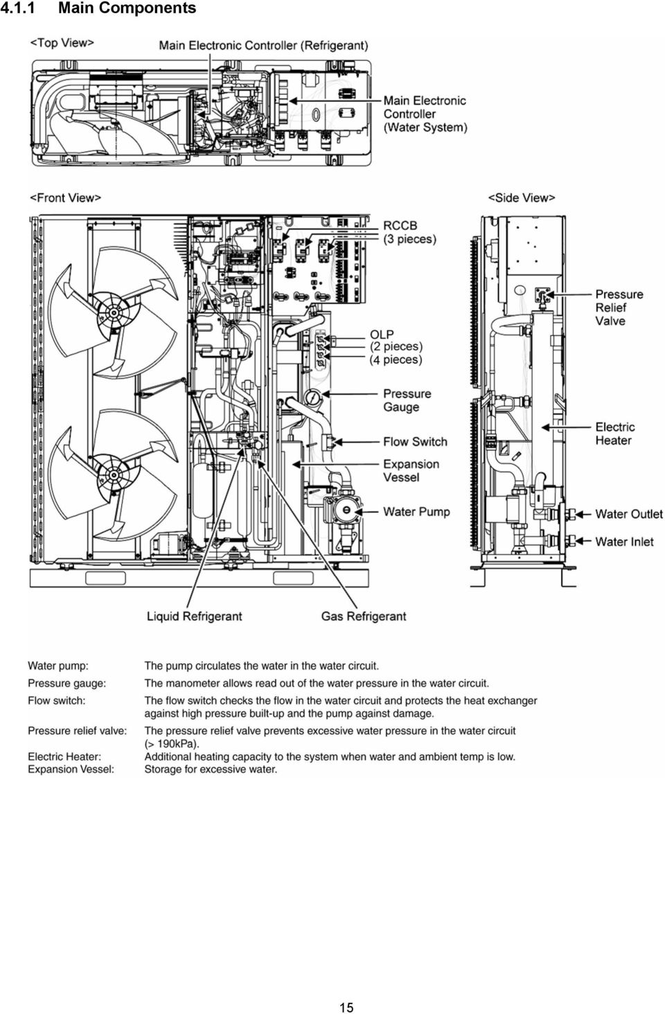
6 Thermostat Protection Device Item Unit Monobloc Unit Electronic Control Electronic Control Item Unit Water System Performance Test Condition EUROVENT Operation Range Outdoor Ambient C -20 ~ 35 Water Outlet C 25 ~ 55 Internal Pressure Differential kpa 15.0 Refrigerant Pipe Diameter Liquid mm (inch) 9.52 (3/8) Gas mm (inch) (5/8) Water Pipe Diameter Inlet mm (inch) 30 (1-3/16) Outlet mm (inch) 30 (1-3/16) Water Drain Hose Inner Diameter mm (inch) (19/32) Pump Motor Type Capacitor Run Induction Motor (5 μf) No. of Speed 3 Input Power W 180 Hot Water Coil Type Brazed Plate No. of Plates 60 Size (W x H x L) mm Water Flow Rate l/min (m 3 /h) 25.8 (1.6) Pressure Relief Valve Water Circuit kpa Open: 190, Close: 186 and below Flow Switch Magnetic Lead Switch Protection Device A Residual Current Circuit Breaker (40) Expansion Vessel Volume I 10 MWP bar 1 Capacity of Integrated Electric Heater kw 3.00 Note: Heating capacities are based on outdoor air temperature of 7 C Dry Bulb (44.6 F Dry Bulb), 6 C Wet Bulb (42.8 F Wet Bulb) with controlled indoor water inlet temperature of 30 C and water outlet temperature of 35 C. Specification are subjected to change without prior notice for further improvement. 6
 mm 93 100 325 Water Flow Rate l/min (m 3 /h) 25.8 (1.")
7 2.2 WH-MDF12C9E8 Item Unit Refrigerant System Performance Test Condition EUROVENT Heating Capacity kw BTU/h kcal/h COP W/W 4.67 kcal/hw 4.02 Air Flow m 3 /min (ft 3 /min) 80.0 (2830) Refrigeration Control Device Expansion Valve Refrigeration Oil cm 3 FV50S (1200) Refrigerant (R410A) kg (oz) 2.30 (81.2) Pipe Diameter Liquid mm (inch) 9.52 (3/8) Compressor Fan Gas mm (inch) (5/8) Type Hermetic Motor Motor Type Brushless (4-poles) Rated Output kw 4.30 Type Propeller Fan Material PP Motor Type Induction (8-poles) Input Power W Output Power W 60 Heat Exchanger Fan Speed rpm 510 (Top Fan) 550 (Bottom Fan) Fin material Aluminium (Pre Coat) Fin Type Corrugated Fin Row Stage FPI Size (W H L) mm Dimension Item Unit Monobloc Unit Height mm (inch) 1410 (55.5) Width mm (inch) 1283 (50.5) Depth mm (inch) 320 (12.6) Net Weight kg (lbs) 157 (346) Noise Level db-a 50 Power Level db 67 Power Source (Phase, Voltage, Cycle) ø Three V 400 Hz 50 Input Power kw 2.57 Starting Current A 3.9 Running Current A 3.9 Max. Current/Max. Input Power Heatpump unit (Heatpump unit + Back-up Heater) A/kW 8.8 / 5.85 (Separate ELCB) Back-up Heater: Max. Current/Max. Input Power A/kW 13.0 / 9.00 Tank Heater [1 Phase, 230V]: Max. Current/ Max. Input Power A/kW 13.0 / 3.00 Power Factor % 96 Power factor means total figure of compressor and outdoor fan motor. Power Cord Number of core - Length m (ft) - Thermostat Electronic Control Protection Device Electronic Control 7
 Input Power W Output Power W 60 Heat Exchanger Fan Speed rpm 510 (Top Fan) 550 (Bottom Fan) Fin material Aluminium (Pre Coat) Fin Type")
8 Item Unit Water System Performance Test Condition EUROVENT Operation Range Outdoor Ambient C -20 ~ 35 Water Outlet C 25 ~ 55 Internal Pressure Differential kpa 27.5 Refrigerant Pipe Diameter Liquid mm (inch) 9.52 (3/8) Gas mm (inch) (5/8) Water Pipe Diameter Inlet mm (inch) 30 (1-3/16) Outlet mm (inch) 30 (1-3/16) Water Drain Hose Inner Diameter mm (inch) (19/32) Pump Motor Type Capacitor Run Induction Motor (5 μf) No. of Speed 3 Input Power W 180 Hot Water Coil Type Brazed Plate No. of Plates 60 Size (W x H x L) mm Water Flow Rate l/min (m 3 /h) 34.4 (2.1) Pressure Relief Valve Water Circuit kpa Open: 190, Close: 186 and below Flow Switch Magnetic Lead Switch Protection Device A Residual Current Circuit Breaker (40) Expansion Vessel Volume I 10 MWP bar 1 Capacity of Integrated Electric Heater kw 9.00 Note: Heating capacities are based on outdoor air temperature of 7 C Dry Bulb (44.6 F Dry Bulb), 6 C Wet Bulb (42.8 F Wet Bulb) with controlled water inlet temperature of 30 C and water outlet temperature of 35 C. Specification are subjected to change without prior notice for further improvement. 8
 mm 93 100 325 Water Flow Rate l/min (m 3 /h) 34.4 (2.")
9 2.3 WH-MDF14C9E8 Item Unit Refrigerant System Performance Test Condition EUROVENT Heating Capacity kw BTU/h kcal/h COP W/W 4.50 kcal/hw 3.87 Air Flow m 3 /min (ft 3 /min) 84.0 (2970) Refrigeration Control Device Expansion Valve Refrigeration Oil cm 3 FV50S (1200) Refrigerant (R410A) kg (oz) 2.30 (81.2) Pipe Diameter Liquid mm (inch) 9.52 (3/8) Compressor Fan Gas mm (inch) (5/8) Type Hermetic Motor Motor Type Brushless (4-poles) Rated Output kw 4.30 Type Propeller Fan Material PP Motor Type Induction (8-poles) Input Power W Output Power W 60 Heat Exchanger Fan Speed rpm 540 (Top Fan) 580 (Bottom Fan) Fin material Aluminium (Pre Coat) Fin Type Corrugated Fin Row Stage FPI Size (W H L) mm Dimension Item Unit Monobloc Unit Height mm (inch) 1410 (55.5) Width mm (inch) 1283 (50.5) Depth mm (inch) 320 (12.6) Net Weight kg (lbs) 157 (346) Noise Level db-a 51 Power Level db 68 Power Source (Phase, Voltage, Cycle) ø Three V 400 Hz 50 Input Power kw 3.11 Starting Current A 4.7 Running Current A 4.7 Max. Current/Max. Input Power Heatpump unit (Heatpump unit + Back-up Heater) A/kW 9.4 / 6.25 (Separate ELCB) Back-up Heater: Max. Current/Max. Input Power A/kW 13.0 / 9.00 Tank Heater [1 Phase, 230V]: Max. Current/ Max. Input Power A/kW 13.0 / 3.00 Power Factor % 96 Power factor means total figure of compressor and outdoor fan motor. Power Cord Number of core - Length m (ft) - Thermostat Electronic Control Protection Device Electronic Control 9
 Input Power W Output Power W 60 Heat Exchanger Fan Speed rpm 540 (Top Fan) 580 (Bottom Fan) Fin material Aluminium (Pre Coat) Fin Type")
10 Item Unit Water System Performance Test Condition EUROVENT Operation Range Outdoor Ambient C -20 ~ 35 Water Outlet C 25 ~ 55 Internal Pressure Differential kpa 36.0 Refrigerant Pipe Diameter Liquid mm (inch) 9.52 (3/8) Gas mm (inch) (5/8) Water Pipe Diameter Inlet mm (inch) 30 (1-3/16) Outlet mm (inch) 30 (1-3/16) Water Drain Hose Inner Diameter mm (inch) (19/32) Pump Motor Type Capacitor Run Induction Motor (5 μf) No. of Speed 3 Input Power W 180 Hot Water Coil Type Brazed Plate No. of Plates 60 Size (W x H x L) mm Water Flow Rate l/min (m 3 /h) 40.1 (2.4) Pressure Relief Valve Water Circuit kpa Open: 190, Close: 186 and below Flow Switch Magnetic Lead Switch Protection Device A Residual Current Circuit Breaker (40) Expansion Vessel Volume I 10 MWP bar 1 Capacity of Integrated Electric Heater kw 9.00 Note: Heating capacities are based on outdoor air temperature of 7 C Dry Bulb (44.6 F Dry Bulb), 6 C Wet Bulb (42.8 F Wet Bulb) with controlled indoor water inlet temperature of 30 C and water outlet temperature of 35 C. Specification are subjected to change without prior notice for further improvement. 10
 mm 93 100 325 Water Flow Rate l/min (m 3 /h) 40.1 (2.")
11 2.4 WH-MDF16C9E8 Item Unit Refrigerant System Performance Test Condition EUROVENT Heating Capacity kw BTU/h kcal/h COP W/W 4.23 kcal/hw 3.64 Air Flow m 3 /min (ft 3 /min) 90.0 (3180) Refrigeration Control Device Expansion Valve Refrigeration Oil cm 3 FV50S (1200) Refrigerant (R410A) kg (oz) 2.30 (81.2) Pipe Diameter Liquid mm (inch) 9.52 (3/8) Compressor Fan Gas mm (inch) (5/8) Type Hermetic Motor Motor Type Brushless (4-poles) Rated Output kw 4.30 Type Propeller Fan Material PP Motor Type Induction (8-poles) Input Power W Output Power W 60 Heat Exchanger Fan Speed rpm 580 (Top Fan) 620 (Bottom Fan) Fin material Aluminium (Pre Coat) Fin Type Corrugated Fin Row Stage FPI Size (W H L) mm Dimension Item Unit Monobloc Unit Height mm (inch) 1410 (55.5) Width mm (inch) 1283 (50.5) Depth mm (inch) 320 (12.6) Net Weight kg (lbs) 157 (346) Noise Level db-a 53 Power Level db 70 Power Source (Phase, Voltage, Cycle) ø Three V 400 Hz 50 Input Power kw 3.78 Starting Current A 5.7 Running Current A 5.7 Max. Current/Max. Input Power Heatpump unit (Heatpump unit + Back-up Heater) A/kW 9.9 / 6.59 (Separate ELCB) Back-up Heater: Max. Current/Max. Input Power A/kW 13.0 / 9.00 Tank Heater [1 Phase, 230V]: Max. Current/ Max. Input Power A/kW 13.0 / 3.00 Power Factor % 96 Power factor means total figure of compressor and outdoor fan motor. Power Cord Number of core - Length m (ft) - Thermostat Electronic Control Protection Device Electronic Control 11
 Input Power W Output Power W 60 Heat Exchanger Fan Speed rpm 580 (Top Fan) 620 (Bottom Fan) Fin material Aluminium (Pre Coat) Fin Type")
12 Item Unit Water System Performance Test Condition EUROVENT Operation Range Outdoor Ambient C -20 ~ 35 Water Outlet C 25 ~ 55 Internal Pressure Differential kpa 47.5 Refrigerant Pipe Diameter Liquid mm (inch) 9.52 (3/8) Gas mm (inch) (5/8) Water Pipe Diameter Inlet mm (inch) 30 (1-3/16) Outlet mm (inch) 30 (1-3/16) Water Drain Hose Inner Diameter mm (inch) (19/32) Pump Motor Type Capacitor Run Induction Motor (5 μf) No. of Speed 3 Input Power W 180 Hot Water Coil Type Brazed Plate No. of Plates 60 Size (W x H x L) mm Water Flow Rate l/min (m 3 /h) 45.9 (2.8) Pressure Relief Valve Water Circuit kpa Open: 190, Close: 186 and below Flow Switch Magnetic Lead Switch Protection Device A Residual Current Circuit Breaker (40) Expansion Vessel Volume I 10 MWP bar 1 Capacity of Integrated Electric Heater kw 9.00 Note: Heating capacities are based on outdoor air temperature of 7 C Dry Bulb (44.6 F Dry Bulb), 6 C Wet Bulb (42.8 F Wet Bulb) with controlled water inlet temperature of 30 C and water outlet temperature of 35 C. Specification are subjected to change without prior notice for further improvement. 12
 mm 93 100 325 Water Flow Rate l/min (m 3 /h) 45.9 (2.")
13 3. Features Inverter Technology - Energy saving High Efficiency Compact Design Environment Protection - Non-ozone depletion substances refrigerant (R410A) Easy to use remote control Weekly Timer setting Quality Improvement - Random auto restart after power failure for safety restart operation - Gas leakage protection - Prevent compressor reverse cycle - Inner protector to protect compressor Serviceability Improvement - Breakdown Self Diagnosis function - System Status Check Buttons for servicing purpose - System Pumpdown Button for servicing purpose - Front maintenance design for monobloc unit Operation Condition HEATING Water outlet temperature ( C) Ambient temperature ( C) Maximum Minimum NOTICE : When the outdoor temperature is out of the above temperature range, the heating capacity will drop significantly and monobloc unit might stop for protection control. 13
 Ambient temperature ( C) Maximum 55 35 Minimum 25-20 NOTICE : When the outdoor temperature is out of the above temperature")
14 4. Location of Controls and Components 4.1 Monobloc Unit 14

15 4.1.1 Main Components 15
16 4.1.2 Location of Control Remote Control The user interface allows the installer and user to setup, use and maintain the unit. 16

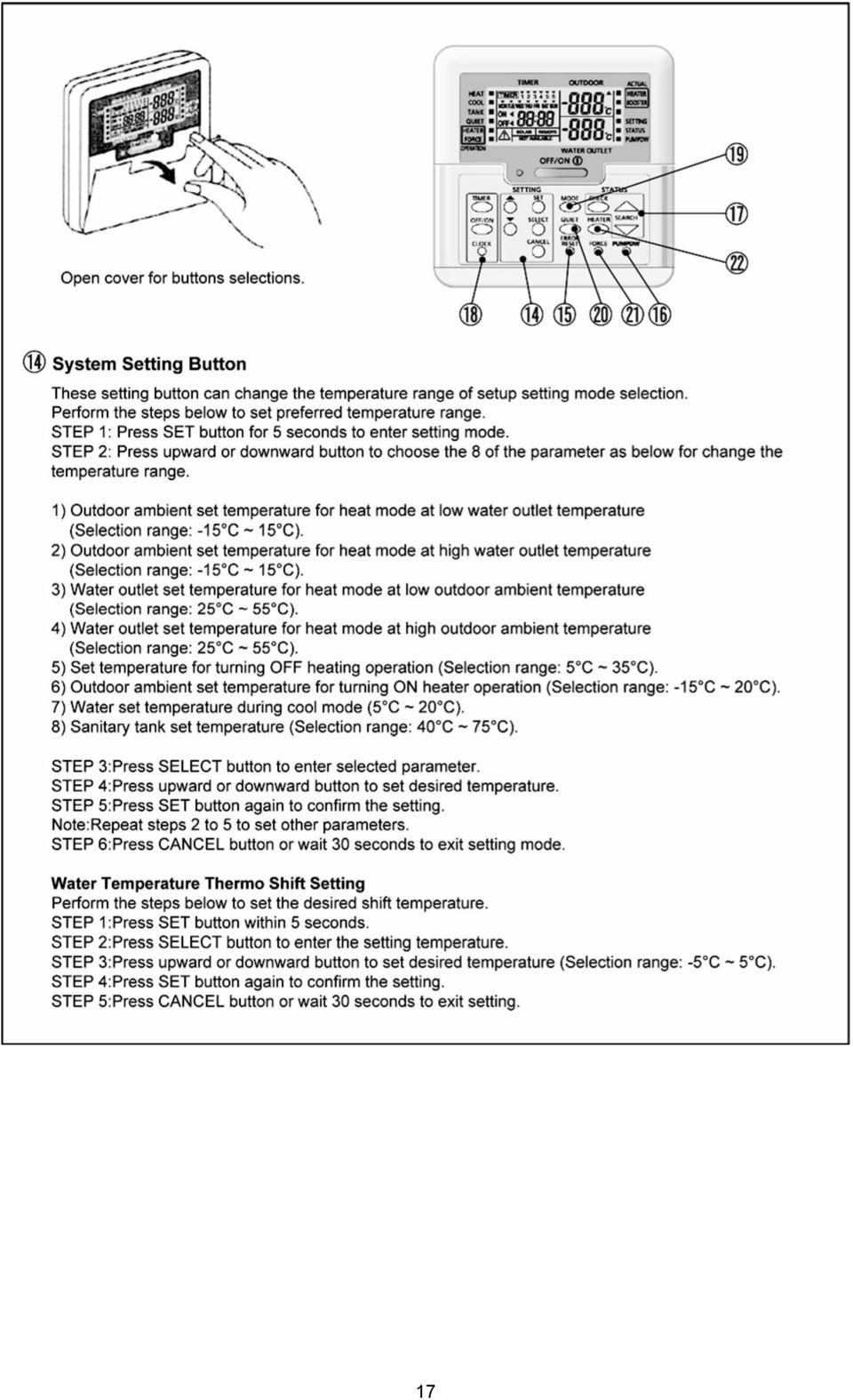
17 17
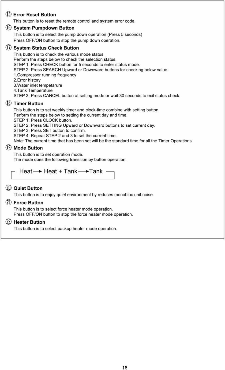
18 18
19 4.1.3 Weekly Timer Setting 19

20 4.1.4 Setting Up The Special Functions 20

21 5. Dimensions 5.1 Monobloc Unit 21
22 6. Refrigeration And Water Cycle Diagram 22
23 23
24 7. Block Diagram 7.1 WH-MDF09C3E8 24
25 7.2 WH-MDF12C9E8 WH-MDF14C9E8 WH-MDF16C9E8 25
26 8. Wiring Connection Diagram 8.1 WH-MDF09C3E8 26
27 27
28 8.2 WH-MDF12C9E8 WH-MDF14C9E8 WH-MDF16C9E8 28
29 29
30 9. Electronic Circuit Diagram 9.1 WH-MDF09C3E8 30
31 31
32 9.2 WH-MDF12C9E8 WH-MDF14C9E8 WH-MDF16C9E8 32
33 33
34 10. Printed Circuit Board 10.1 Water System Main Printed Circuit Board 34
35 Solar Printed Circuit Board (Optional) 35
36 10.2 Refrigerant System Main Printed Circuit Board 36
37 Noise Filter Printed Circuit Board 37
38 11. Installation Instruction Monobloc Unit Dimension Diagram 38
39 Main Components 39
40 11.1 Select the Best Location Install Monobloc unit at outdoor only. Avoid location where ambient temperature is below -20 C. Must install on a flat horizontal and solid hard surface. A place where should not be any heat source or steam near the Monobloc unit. A place where air circulation is good. A place where drainage can be easily done. A place where Monobloc unit s operation noise will not cause discomfort to the user. A place where accessible for maintenance. Ensure to keep minimum distance of spaces as illustrated below from wall, ceiling, or other obstacles. A place where flammable gas leaking might not occur. A place where the Monobloc unit s piping and wiring lengths come within reasonable ranges. If an awning is built over the unit to prevent direct sunlight or rain, be careful that heat radiation from the condenser is not obstructed. Do not place any obstacles which may cause a short circuit of the discharged air. Avoid install the Monobloc unit at a location where suction side may be exposed directly to wind. If Monobloc unit installed near sea, region with high content of sulphur or oily location (e.g. machinery oil, etc.), it lifespan maybe shorten. When installing the product in a place where it will be affected by typhoon or strong wind such as wind blowing between buildings, including the rooftop of a building and a place where there is no building in surroundings, fix the product with an overturn prevention wire, etc. (Overturn prevention fitting model number: K-KYZP15C) When connecting solar pump station cable between Monobloc unit and solar pump station, the distance between both apparatuses shall be 2 ~ 8 meters and the length of the said cable must be shorter than 10 meters. Fail to do so may lead to abnormal operation to the system Monobloc Unit Installation Monobloc unit will become heavy when filled with water. Therefore, please install the Monobloc unit on strong concrete floor, by considering weight of unit and water. Fix Mono bloc unit on the concrete floor with M12 anchor bolt at 4 locations. Pull-out strength of these anchor bolts must be above 15000N. 40
41 11.3 Piping Installation WARNING This section is for authorized and licensed electrician / water system installer only. Work behind the front plate secured by screws must only be carried out under supervision of qualified contractor, installation engineer or service person. Please engage a licensed water circuit installer to install this water circuit. The minimum requirement of water in the system is 50 litres.if this value could not be achieved, please install additional buffer tank (field supply). This water circuit must comply with relevant European and national regulations (including EN61770), and local building regulation codes. Ensure the components installed in the water circuit could withstand water pressure during operation. Do not apply excessive force to piping that may damage the pipes. Do not install any valve between Monobloc unit and water piping to avoid accidental closure of water supply to the Monobloc unit. Use Rp 1 ¼ nut for both water inlet and water outlet connection and clean all piping with tap water before install. If old heat pump terminal / tank is utilized, please clean the dust properly before installation. Refer Diagram 3.1 for installation of 3-way Valve Kit. Must install an external filter (30 mesh or more, field supply) before water inlet connector of Monobloc unit (indicate with WATER IN ). Connect the external of Monobloc unit (indicate with WATER OUT ) to boiler tank inlet. Fail to connect the tube appropriately might causing the Monobloc unit malfunction. Choose proper sealer which can withstand the pressures and temperatures of the system. Make sure to use two spanners to tighten the connection. Further tighten the nuts with torque wrench in specified torque as stated in the table. Model WH-MDF09C3E5 WH-MDF12C6E5 WH-MDF14C6E5 WH-MDF16C6E5 Nut size (Torque) Water Rp 1 1/4" [117.6 N m] If non-brass metallic piping is used for installation, make sure to insulate the piping to prevent galvanic corrosion. Do not use worn out piping. Make sure to insulate the water circuit piping (insulator thickness : 20mm or more) to prevent reduction of heating capacity, as well as avoid freezing of the outdoor water circuit piping during winter season. After installation, check the water leakage condition in connection area during test run. In case of a power supply failure or pump operating failure, drain the system (as suggested in the figure below) When water is idle inside the system, freezing up is very likely to happen which could damage the system Drainage piping installation Use a drain hose with inner diameter of 15 mm. The hose must be installed in a continuously downward direction and left open to the frost-free atmosphere. If drain hose is long, use a metal support fixture along the way to eliminate the wavy pattern of drain tube. The water may drip from this discharge hose. Therefore must guide the hose without close or block the outlet of the hose. Do not insert this hose into sewage hose or cleaning hose that may generate ammonia gas, sulfuric gas, etc. If necessary, use a hose clamp to tighten the hose at drain hose connector to prevent it from leaking. 41
42 11.4 Connect The Cord And Cable To Monobloc Unit (REFER TO WIRING DIAGRAM AT UNIT FOR DETAIL) 1. Cable connection to the power supply through isolating device (Disconnecting means). Isolating device (Disconnecting means) should have minimum 3.0 mm contact gap. Connect the approved polychloroprene sheathed power supply 1 cord (3 x 4.0 or 6.0 mm 2 ) and power supply 2 cord (3 x 4.0 mm 2 ) and power supply 3 cord (3 x 1.5 mm 2 ), type designation IEC 57 or heavier cord to the RCCB, and to the other end of the cord to isolating device (Disconnecting means). 2. To avoid cable and cord harmed by sharp edge, cable and cord must go through bushing (located at the right side of Monobloc unit) before carry out electrical connection. The bushing must be used and must not take off. 3. Secure the cable onto the control board with the holder (clamper). Connecting with external device (optional) 1. All connections shall follow to the local national wiring standard. 2. It is strongly recommended to use manufacturer-recommended parts and accessories for installation. 3. Maximum output power of booster heater shall be 3 kw. Booster Heater s cord must be (3 x min 1.5 mm 2 ), of type designation IEC 57 or heavier. 4. Three-way Valve shall be spring and electronic type. Valve s cable shall be (3 x min 0.5 mm 2 ), of type designation IEC 57 or heavier, or similarly double insulation sheathed cable. * note: - Shall be CE marking compliance component. - It shall be directed to heating mode when it is OFF. - Maximum load for the valve is 3VA. 42
43 5. Receiver shall be connected to Room Thermostat, refer to Field Supply Accessories table for details. Receiver s cable must be (4 or 3 x min 0.5 mm 2 ), double insulation layer of PVC-sheathed or polychloroprene sheathed cable. (connection refer to Diagram 4.2). 6. Tank OLP s cable must be (2 x min 0.5 mm 2 ), double insulation layer of PVCsheathed or polychloroprene sheathed cable. * note: if such connection deemed NO necessary for tank OLP, please connect jumper between terminal no #13 and # Tank Sensor shall be resistance type, please refer to Graph 4.1 for the characteristic and details of sensor. Its cable shall be (2 x min 0.3 mm 2 ), double insulation layer (with insulation strength of min 30V) of PVC-sheathed or polychloroprene sheathed cable. 8. External Controller shall be connected to 1-pole switch with min 3.0mm contact gap. (connection refer to Diagram 4.3). Its cable must be (2 x min 0.5 mm 2 ), double insulation layer of PVC-sheathed or polychloroprene sheathed cable. * note: - When making such connection, kindly remove the jumper between terminal no #17 and #18. - Switch used shall be CE compliance component. - Maximum operating current shall be less than 3A rms. 9. Solar Three-way Valve s cable shall be (3 x min 0.5 mm 2 ), double insulation layer PVC-sheathed or polychloroprene sheathed cable. 10. Must install Solar Connection PCB to Monobloc unit when Solar Pump Station is utilized. Refer Solar Connection PCB s installation instruction for detail of installation. 11. Solar Pump Station s cable shall be (2 x min 0.5 mm 2 ), of double insulation PVC-sheathed or polychloroprene sheathed cable. Strongly recommended install with maximum length of 10 meter only. Terminal screw Tightening torque N cm {kgf cm} M4 157~196 {16~20} M5 196~245 {20~25} Wire Stripping And Connecting Requirement Connecting Requirement For WH-MDF09C3E5: The equipment s power supply 1 complies with IEC/EN provided that the short-circuit power S sc is greater than or equal to 858kW (for WH-MDF09C3E5) at the interface point between the user s supply and the public system. It is the responsibility of the installer or user of the equipment to ensure, by consultation with the distribution network operator if necessary, that the equipment is connected only to a supply with a short-circuit power S sc greater than or equal to 858kW. 43
44 The equipment s power supply 1 shall be connected to a suitable supply network, having service current capacity 100A per phase. Please liaise with supply authority to ensure that the service current capacity at the interface point is sufficient for the installation of the equipment. The equipment s power supply 2 complies with IEC/EN The equipment s power supply 2 shall be connected to a suitable supply network, with the following maximum permissible system impedance Z max at the interface for models: WH-MDF09C3E5 : 0.236Ω Please liaise with supply authority to ensure that the power supply 2 is connected only to a supply of that impedance or less. For WH-MDF12C6E5, WH-MDF14C6E5, WH-MDF16C6E5: The equipment s power supply 1 complies with IEC/EN provided that the short-circuit power S sc is greater than or equal to 858kW (for WH-MDF12C6E5, WH-MDF14C6E5, WH-MDF16C6E5) at the interface point between the user s supply and the public system. It is the responsibility of the installer or user of the equipment to ensure, by consultation with the distribution network operator if necessary, that the equipment is connected only to a supply with a short-circuit power S sc greater than or equal to 858kW. The equipment s power supply 1 shall be connected to a suitable supply network, having service current capacity 100A per phase. Please liaise with supply authority to ensure that the service current capacity at the interface point is sufficient for the installation of the equipment. The equipment s power supply 2 complies with IEC/EN The equipment s power supply 2 shall be connected to a suitable supply network, with the following maximum permissible system impedance Z max at the interface for models: WH-MDF12C6E5, WH-MDF14C6E5, WH-MDF16C6E5 : Ω Please liaise with supply authority to ensure that the power supply 2 is connected only to a supply of that impedance or less. The equipment s power supply 3 complies with IEC/EN The equipment s power supply 3 shall be connected to a suitable supply network, with the following maximum permissible system impedance Z max at the interface for models: WH-MDF12C6E5, WH-MDF14C6E5, WH-MDF16C6E5 : Ω Please liaise with supply authority to ensure that the power supply 3 is connected only to a supply of that impedance or less Wired Remote Controller Installation Selecting The Installation Location Allow sufficient space around the remote controller (1) as shown in the illustration above. Install in a place which is away from direct sunlight and high humidity. Install in a flat surface to avoid warping of the remote controller. If installed to a wall with an uneven surface, damage to the LCD case or operation problems may result. Install in a place where the LCD can be easily seen for operation. (Standard height from the floor is 1.2 to 1.5 meters.) Avoid installing the remote controller cable near refrigerant pipes or drain pipes, else it will cause electrical shock or fire. 44
45 Installing The Remote Controller Unit To The Wall 1. Remove the remote controller (1) lower case. (Insert a flat-tipped screw driver or similar tool 2 to 3 mm into one of the gaps at the bottom of the case, and twist to open. Refer to the illustration at right.) Be careful not to damage the lower case. 2. Do not remove the protective tape which is affixed to the upper case circuit board when remove the remote controller lower case. 3. Secure the lower case to an outlet box or wall. Refer to (A) or (B) instructions below depending on your choice of cable installation. 4. Be sure to use only the screws provided. 5. Do not over tighten the screws, as it may result in damage to the lower case. A. If Remote Controller Cable Is Embedded 1. Embed an outlet box (JIS C 8336) into the wall. Outlet box may be purchased separately. Medium-sized square outlet box (obtain locally) Part No. DS3744 (Panasonic Co., Ltd.) or equivalent. 2. Secure the remote controller lower case to the outlet box with the two accessory screws (3). Make sure that the lower case is flat against the wall at this time, with no bending. 3. Pass the remote controller cable (2) into the box. 4. Route the remote controller cable (2) inside the lower case through rear feeding-out direction. 5. Insert firmly the connector of remote controller cable (2) to connector (CON1) in the upper case circuit board. [Refer to the illustration at below.] 6. Secure the remote controller upper case to the lower case with the tabs provided. B. If Remote Controller Cable Is Exposed 1. Install the remote controller lower case to the wall with the two accessory screws (4). 2. Fasten the screws properly until screw head is lower than the rib and reach the base of remote controller lower case to ensure they do not damage the PCB inside the remote controller (1). 3. The feeding-out direction for the remote controller cable can be either via top, left or right side. 4. Use nipper to cut a notch at the upper case. (Select the intended feeding-out position) 5. Route the remote controller cable (2) inside the lower case in accordance with the intended feedingout direction. (Refer to the illustration at below) 6. Insert firmly the connector of remote controller cable (2) to connector (CON1) in the upper case circuit board (Refer to the illustration at below) 7. Secure the remote controller upper case to the lower case with the tabs provided. When the wall is hollow, please be sure to use the sleeve for remote controller cable to prevent dangers caused by mice biting the cable. 45
46 Connecting The Remote Controller Cable To Monobloc Unit Be sure to turn off the main power before installing and connecting the remote controller. Otherwise, it will cause the electrical shock. 1. Remove the cabinet front plate and cabinet top plate. 2. Connect the remote controller s connector to PCB - CN-REMOTE2 as shown in below illustration. (Refer wiring diagram for detail.) 3. Guide the remote controller cable through the clamper and Bushing. (Refer illustration How to connect Remote Controller to PCB for detail.) 4. Reinstall the cabinet front plate and cabinet top plate after connection complete Disposal of Monobloc Unit Drain Water If the unit is used in an area where temperature falls below 0 C for 2 or 3 days in succession, it is recommended not to use a drain elbow, for the drain water freezes and the fan will not rotate. 46
47 12. Operation and Control 12.1 Basic Function Inverter control, which equipped with a microcomputer in determining the most suitable operating mode as time passes, automatically adjusts output power for maximum comfort always. In order to achieve the suitable operating mode, the microcomputer maintains the set temperature by measuring the temperature of the environment and performing temperature shifting. The compressor at monobloc unit is operating following the frequency instructed by the microcomputer at monobloc unit that judging the condition according to internal water setting temperature and water outlet temperature Internal Water Setting Temperature Once the operation starts, control panel setting temperature will be taken as base value for temperature shifting processes. These shifting processes are depending on the monobloc unit settings and the operation environment. The final shifted value will be used as internal water setting temperature and it is updated continuously whenever the electrical power is supplied to the unit Heating Operation Thermostat control Compressor is OFF when Water Outlet Temperature - Internal Water Setting Temperature > 2 C for continuously 3 minutes. Compressor is ON after waiting for 3 minutes, if the Water Outlet Temperature - Water Inlet Temperature (temperature at thermostat OFF is triggered) < -3 C Tank Mode Operation Control contents: 3 ways valve direction - 3 ways valve switch and fix to tank side. Heatpump Thermostat characteristic - Water set temperature = Tank set temperature or [55 C] whichever lower. - Heatpump Water Outlet set temperature is set to Maximum (55 C) at tank mode i. Case 1 - THERMO OFF TEMP: 1 THERMO OFF TEMP = Water set temperature + [+2 C]. 2 Tank temperature > THERMO OFF TEMP for continuous 3 minutes, heatpump OFF and water pump OFF. - THERMO ON TEMP: 1 THERMO ON TEMP = Water set temperature + [-3 C]. 2 When detect tank temperature < THERMO ON TEMP, water pump ON for 3 minute then heatpump ON. - Pump ON when Tank temperature is less than tank temperature when Heatpump Thermo Off - [-3 C]. 47
48 ii. Case 2 - Heatpump THERMO OFF TEMP: 1 Heatpump THERMO OFF TEMP = 55 C + [+2 C]. 2 Water outlet temperature > Heatpump THERMO OFF TEMP for continuous 3 minutes, heatpump OFF but water pump ON. - Heatpump THERMO ON TEMP: 1 Heatpump THERMO ON TEMP = Water inlet during thermo off time + [-3 C]. 2 Heatpump ON back when water outlet temperature < Heatpump THERMO ON TEMP. iii. Case 3 - Heatpump THERMO OFF TEMP: 1 Water inlet temperature > 52 C for continuous 60 seconds, heatpump OFF and water pump OFF. - Heatpump THERMO ON TEMP: 1 Heatpump THERMO ON TEMP = Water inlet during thermo off time + [-3 C]. 2 Water pump ON back when tank temp. < Tank temp. when heatpump thermo off + [-3 C]. 3 Heatpump only ON back after water outlet temperature < Heatpump THERMO ON TEMP & water pump ON for 3 minutes. Booster heater control - Booster heater turn On and Off follow normal operation. - Booster heater turn ON condition: 1 During startup time (initialization), Booster heater turn ON after DELAY TIMER. 2 When tank temperature lower than HEATER ON TEMP 3 20 minutes from previous heater off. - Booster heater turn OFF condition: 1 When tank temperature higher than tank set temperature for continous 15 sec. Solar 3 way valve - Solar pump operates follow solar operation specification. Others - Indoor backup heater cannot be ON during tank mode only. 48
49 Heat + Tank Mode Operation Setting 1: When Heating priority is set by control panel: 1 3 ways valve control: o 3 ways valve switch and fix to room side. 2 Heatpump operation control: o Heatpump operate follow normal operation. 3 Backup Heater control: o Backup heater operate follow normal operation. 4 Booster heater control: o Booster heater On/Off follow normal operation. 5 Solar 3 way valve: o Solar 3 way valve operates follow solar operation specification. * Under solar priority is set condition, when solar 3 way valve is ON, booster heater turn OFF. Setting 2: When heating priority is not set by control panel: When Solar Priority is set/not set by control panel: 1 3 ways valve control: o 3 ways valve switch to room side during heating heat-up interval, and switch to tank side during tank heat-up interval. Both mode will switch alternatively. 2 Heatpump operation control: o During heating heat-up interval - Follow normal heating operation. Under solar priority set condition: - Always detect the tank temperature after heating heat-up interval. Switch only to tank heat-up interval and start counting tank heat-up timer when tank temperature < THERMO ON TEMP AND solar 3WV OFF Under solar priority not set condition: - Always detect the tank temperature after heating heat-up interval. Switch only to tank heat-up interval and start counting tank heat-up timer when tank temperature < THERMO ON TEMP * THERMO ON TEMP is defined form following Case1 to Case4. o During tank heat-up interval - Heatpump tank target temperature = Tank set temperature or [55 C] whichever lower - Heatpump Water Outlet set temperature is set to Maximum [55 C] during tank interval 49
50 i. Case 1 - THERMO OFF TEMP: 1. THERMO OFF TEMP = Heatpump tank target temperature + [+2 C]. 2. Tank temperature > THERMO OFF TEMP for continuous 3 minutes, switch 3 ways valve to room side. End Tank heat-up interval and start count heating heat-up interval. - THERMO ON TEMP: 1. THERMO ON TEMP = Heatpump tank target temperature + [-3 C]. 2. After Heating heat-up interval, always detect tank temperature. Switch to next tank heat-up interval when tank temperature < THERMO ON TEMP ii. Case 2 - Heatpump THERMO OFF TEMP: 1. Heatpump THERMO OFF TEMP = 55 C + [+2 C]. 2. Water outlet temperature > Heatpump THERMO OFF TEMP for continuous 90 seconds, switch 3 ways valve to room side. End Tank heat-up interval and start count heating heat-up interval. - THERMO ON TEMP: 1. THERMO ON TEMP = Tank temp. when heatpump thermo off + [-3 C]. 2. After Heating heat-up interval, always detect tank temperature. Switch to next tank heat-up interval when tank temperature < THERMO ON TEMP iii. Case 3 - Heatpump THERMO OFF TEMP: 1. Water inlet temperature > 52 C for continuous 60 seconds, switch 3 ways valve to room side. End tank heat-up interval and start count heating heat-up interval. - THERMO ON TEMP: 1. THERMO ON TEMP = Tank temp. when heatpump thermo off + [-3 C]. 2. After Heating heat-up interval, always detect tank temperature. Switch to next tank heat-up interval when tank temperature < THERMO ON TEMP iv. Case 4 (Only during solar priority is set condition) When solar pump ON, tank heat-up interval end early and 3 ways valve switch to room side. - THERMO ON TEMP: 1. THERMO ON TEMP = Heatpump tank target temperature + [-3 C]. 2. After Heating heat-up interval, always detect tank temperature. Switch to next tank heat-up interval when tank temperature < THERMO ON TEMP and solar 3 way valve OFF. 3 Backup heater control: o During heating heat up interval. - Follow normal backup heater control operation. o During tank heat-up interval. - Backup heater OFF during this interval. 4 Booster heater control: o During heating heat-up interval. - Booster heater ON/OFF according to booster heater operation control. o During tank heat-up interval. - Once switch from heating heat-up interval to tank heat-up interval, turn off the booster heater and start counting the BOOSTER HEATER DELAY TIMER. - Booster heater turn ON after BOOSTER HEATER DELAY TIMER fufil and tank temperature lower than tank set temperature. - BOOSTER HEATER DELAY TIMER is clear when switch to heating heat-up interval. 5 Solar 3 way valve: o Solar 3WV operates follow solar operation specification. 50
51 * Under solar priority is set condition, when solar 3WV is ON, booster heater turn OFF. * Under solar priority is not set condition, solar 3WV only can ON during heating heat-up interval. 51
52 Setting Water Outlet Temperature for Heat Mode The set temperature define the parameters for the outdoor ambient temperature dependent operation of the unit. Where by the internal water setting temperature is determined automatically depending on the outdoor temperature. The colder outdoor temperatures will result in warmer water and vice versa. The user has the possibility to shift up or down the target water temperature by remote control setting. Water Temp. OUT LO = Low outdoor ambient set temperature OUT HI = High outdoor ambient set temperature H2O LO = Water outlet set temperature at low outdoor ambient temperature H2O HI = Water outlet set temperature at high outdoor ambient temperature H2O LO H2O HI OUT LO OUT HI Change in setting water outlet temperature is updated every 30 minutes Outdoor Temp. Outdoor temperature is updated every 30 minutes when operation ON Heating Mode Operation Time Chart Example 1 3 ways valve control: o 3 ways valve switch and fix to heating side. 2 Heatpump operate follow normal heating operation. 3 Backup heater operate follow normal operation. 4 Solar 3 way valve operates follow solar operation specification Water Temperature Thermo Shift Setting Switchs are ignored during PUMPDW = ON. Switchs are ignored during STATUS = ON. 52
53 ,, SELECT switch are ignored if SETTING = OFF. CANCEL switch is ignored if SETTING = OFF & STATUS = OFF. If SET Switch pressed for less than 5secs, immediately enter water temperature shift setting mode. Once enter this setting mode, SETTING display is ON. This setting mode is used to easily shift the target water outlet temperature. Water Temp. H2O LO H2O HI +5 ±0 Shift value -5 OUT LO OUT HI Outdoor Temp. OUT LO = Low outdoor ambient set temperature OUT HI = High outdoor ambient set temperature H2O LO = Water outlet set temperature at low outdoor ambient temperature H2O HI = Water outlet set temperature at high outdoor ambient temperature Shift Value = Setting water temperature thermo shift Fan Motor Operation Fan motor is adjusted according to operation condition. It starts when compressor starts operation and it stops 30 seconds after compressor stops operation. 53
54 12.2 Water Pump Water Pump Control 1 Once the monobloc unit is ON, the water pump will be ON immediately and no error judgement for 9 minutes. However, during this 9 minutes operation, if there is any abnormality cause at monobloc unit or malfunction, the compressor should be OFF immediately and restart delay after 3 minutes. 2 The system will start checking on the water flow level after operation start for 9 minutes. If water flow level is detected low continuously for 1 minute, the water pump and compressor will be OFF permanently and OFF/ON remote control LED will blink (H62 error occurs) 3 The water pump will remain ON when compressor OFF due to thermostat OFF Pump Down Operation Purpose Ensure the pump down operation when relocating or disposing of the unit. The pump down operation will extract all refrigerant from the piping into the outdoor unit. 1 Make sure the OFF/ON control panel LED is OFF (no operation). 2 Press the Pump Down button to start the pump down operation. 3 No low pressure protection error during pump down operation and 3-way valve will be shift to heating side. 4 Press OFF/ON button to stop the pump down operation Flow Switch Flow Switch Control 1 The water flow switch serve as an overload protector that shuts down the unit when the water level is detected to be low. 2 Detection is Lo (0V) when there is no water flow, and detection is Hi (5V) when there is water flow. 54
55 12.5 Force Heater Mode Operation The backup heater also serves as backup in case of malfunctioning of the outdoor unit. 1 Make sure the OFF/ON control panel LED is OFF (no operation). 2 Press the Force button to start the force heater mode operation. 3 During force heater mode, all other operations are not allowed. 4 Press OFF/ON button to stop the force heater mode operation Monobloc Unit Safety Monobloc Unit Safety Control 1 When water pump is ON, the system will start checking flow switch status (ON/OFF). 2 If the flow switch ON for 10 seconds, the system will check on the water inlet temperature for 10 seconds. If the water inlet temperature not exceeds 80 C, the water pump shall be continuously running with normal mode. If the water inlet temperature exceeds 80 C for continuously 10 seconds, the water pump will be OFF immediately. 3 After water pump OFF for more than 10 minutes, it will be ON back and the monobloc unit safety control checking is restarted Auto Restart Control 1 When the power supply is cut off during the operation of Monobloc unit, the compressor will re-operate after power supply resumes. 55
56 12.8 Indication Panel LED Color Light ON Light OFF Operation Green Operation ON Operation OFF Note: If Operation LED is blinking, there is an abnormality operation occurs Back-Up Heater Control Electric Heater Control 1 Normal Heating Mode o Heater On condition: a. Heater switch is ON b. After Heatpump thermo ON for [30] mins c. After water pump operate [9] mins d. Outdoor air temperature < Outdoor set temperature for heater e. When water outlet temperature < Water set temperature + [-8 C] f. [20] minutes since previous Backup heater Off * When heatpump cannot operate due to error happens during normal operation, heater will go into force mode automatic * Heater need to operate during deice operation o Heater Stop Condition: a. When outdoor set temperature > outdoor set temperature + [+2 C] for continuous 15 secs OR b. When water out temp> water set temperature + [-2 C] for continuous 15 secs OR c. Heater switch is Off OR d. Heatpump thermo-off or OFF condition 2 Force Heater Mode o Heater On Condition: a. After water pump operate [9] mins b. When water outlet temperature < water set temperature + [-8 C] c. [20] minutes since previous Backup heater Off o Heater Stop condition a. Force mode off OR b. When water outlet temperature > water set temperature + [-2 C] for continuous 15 secs * Do not operate heater at the following situation 1 Water outlet temperature sensor, and water inlet sensor abnormal 2 Flow switch abnormal 3 Circulation pump stop condition 4 During Heatpump switch to tank side 56
57 12.10 Tank Booster Heater Control Tank booster heater control Heating operation condition: 1 Booster heater Turn On condition: o After BOOSTER HEATER DELAY TIMER fulfil during heatpump startup time in tank mode, or during switching from heating heat-up interval to tank heat-up interval in heat+tank mode (heating priority not set). o Tank temperature < tank set temperature + [-5 C], o 20 minutes since previous heater off. * BOOSTER HEATER DELAY TIMER is clear when tank heat-up interval end. 2 Booster heater Turn Off condition: o Tank temperature > Tank set temperature + [+2 C] for continuous 15 sec o When BOOSTER HEATER DELAY TIMER start count after switch from heating heat-up interval to tank heat-up interval * DELAY TIMER can be set by control panel Three Way Valve Control Purpose: - 3 ways valve is used to change flow direction of hot water from heatpump between heating side and tank side Control contents: 1 3 ways valve switch Off: o During 3 ways valve switch Off time, the hot water will provide heat capacity to heating side. 2 3 ways valve switch On: o During 3 ways valve switch On time, the hot water will provide heat capacity to tank side. 3 Stop condition: o During stop mode, 3 ways valve will be in switch off position Sterillization Mode 1 During sterillization mode, Tank will be heat up to the sterillize Set temperature for a certain period of time, also set by controller. 2 The function can only be set on timer to operate once in a week. 3 It will be cancelled even when the temperature is not reached after 4 hours. 4 When tank mode is OFF or disabled, sterillization is cancelled Quiet Operation Purpose: - To provide quiet operation compare to normal operation by reduces outdoor unit noise. Starting condition: 1 When quiet button is presses. 2 When quiet request ON time by weekly timer (Refer to remote control.) When any of above mentioned condition is achieved, this control is activated. New target FM speed = Present target FM speed - 80rpm Minimum target FM speed = 200rpm Cancellation condition: 1 Cancel by press quiet button 2 Stop by OFF/ON button 3 When quiet request OFF time by weekly timer When any of above mentioned condition is achieved, this control is cancelled. 57
58 12.14 Solar Operation (Optional) Solar Operation 1 Control according to preset whether solar priority is set or not. 2 When tank connection is NOT set at SETTING mode, Solar operation is disabled. 3 When Pump A (from Solar pump station) is detected On through connection Y3 and Y4, then the Solar pump 3 Way Valve is requested ON (Refer to figure below) Solar Operation Control When solar priority is SET 1 Operation condition: a Solar pump operates if all of the following conditions are fulfilled:- Power On. (regardless operation ON or OFF) There is operation request from Solar pump station. Tank hot water temp is below solar on upper limit temp [EEPROM 1 : 70] C. 2 Stop condition: a Solar pump stops operating when:- No power supply to unit OR There is NO operation request from solar pump station OR Tank hot water temp is above solar off upper limit temp [EEPROM 2 : 77] C. * heatpump OFF OR operate to room side when solar pump operate during solar priority set. * booster heater OFF when solar pump operate during solar priority set. When solar priority is NOT SET 1 Operation condition: a Solar pump operates if all of the following conditions are fulfilled:- Power On. (regardless operation ON or OFF). There is operation request from Solar pump station. Tank hot water temp is below solar on upper limit temp [EEPROM 1 : 70] C. Heatpump thermo OFF in tank mode OR Heatpump operate to room side (During Operation ON and tank mode selected). 2 Stop condition: a Solar pump stops operating when:- No power supply to unit OR There is NO operation request from solar pump station OR Tank hot water temp is above solar off upper limit temp [EEPROM 2 : 77] C. Heatpump thermo ON and operate to tank side. (During Operation ON and tank mode selected). 58
59 59
60 60
61 12.15 External Room Thermostat Control (Optional) Purpose: 1 Better room temperature control to fulfill different temperature request by external room thermostat. Recommended external room thermostat: Maker Siemen (REV200) Siemen (RAA20) Characteristic Touch panel Analog Connection external room thermostat: Wire Connection and thermo characteristic of Siemen REV200: Setting L/L1 (H) Heat Thermo L/L2 (C) Cool Thermo Set Temp < Actual Temp Open Circuit OFF Short Circuit ON Set Temp > Actual Temp Short Circuit ON Open Circuit OFF Wire Connection and thermo characteristic of Siemen RAA20: Setting L/Y1 (H) Heat Thermo L/Y2 (C) Cool Thermo Set Temp < Actual Temp Open Circuit OFF Short Circuit ON Set Temp > Actual Temp Short Circuit ON Open Circuit OFF Control Content: External room thermostat control activate only when remote thermostat connection select YES by Indoor remote control. When indoor running heat mode, refer thermo On/Off from heating line feedback. And when indoor running cool mode, refer thermo On/Off from cooling line feedback. Heatpump Off immediately when receive thermo off feedback. 61
62 13. Protection Control 13.1 Protection Control for All Operations Time Delay Safety Control 1 The compressor will not start for three minutes after stop of operation Seconds Forced Operation 1 Once the compressor starts operation, it will not stop its operation for 30 seconds. 2 However, it can be stopped using remote control Total Running Current Control 1 When the monobloc unit running current exceeds X value, the compressor frequency will decrease. 2 If the monobloc unit running current does not exceed X value, the compressor frequency will return to normal operating frequency. 3 If the monobloc unit running current continue to increase till exceed Y value, compressor will stop, and if this occurs 3 times within 20 minutes, system will stop operation and OFF/ON remote control LED will blink (F16 error occurs). 09C 12C 14C 16C Operation Mode X (A) Y (A) X (A) Y (A) X (A) Y (A) X (A) Y (A) Heating IPM (Power Transistor) Prevention Control A. Overheating Prevention Control 1 When the IPM temperature rises to 95 C, compressor will stop immediately. 2 Compressor will restart delay 3 minutes when the IPM temperature decreases to 90 C. If this condition repeats continuously 3 times within 30 minutes, system will stop operation and OFF/ON remote control LED will blink (F22 error occurs). B. DC Peak Current Control 1 When the current to IPM exceeds set value of 40.1 ± 5.0 A (MDF09C), 44.7 ± 5.0 A (MDF12C, MDF14C, MDF16C), compressor will stop. Compressor will restart after three minutes. 2 If the set value exceeds again for more than 30 seconds after the compressor restarts, operation will restart after two minutes. 3 If the set value exceeds again for within 30 seconds after the compressor restarts, operation will restart after one minute. If this condition repeats continuously for seven times, system will stop operation and OFF/ON remote control LED will blink (F23 error occurs) Compressor Overheating Prevention Control The compressor operating frequency is regulated in accordance to compressor tank temperature as shown in below figures. When the compressor tank temperature exceeds 112 C, compressor will stop, and if this occurs 4 times within 30 minutes, system will stop operation and OFF/ON remote control LED will blink (F20 error occurs). 62
63 Low Frequency Protection Control 1 When the compressor continuously operates at frequency lower than 25 Hz for 240 minutes, the operation frequency will change to 24 Hz for 2 minutes Low Frequency Protection Control 2 When all the below conditions comply, the compressor frequency will change to lower frequency. Temperature, T, for: Heating Outlet water ( C) T < 14 or T 48 Outdoor air ( C) T < 4 or T 24 Indoor heat exchanger ( C) T High Pressure Sensor Control Purpose: - To protect the system operation. Detection period: - After compressor on for 5 minutes. Detection conditions: - When abnormal high voltage detection, 5V or when open circuit detection 0V for 5 seconds continuously. After detection: - When abnormality is detected continue 5 seconds, unit stop operation. - OFF/ON control panel LED will blink (H64 error occurs) Outside Temperature Current Control Crank Case Heater Control Purpose: - For compressor protection during low outdoor ambient operation (during heating low temperature operation). Control content: a. Trigger heater START condition o when the outdoor air temperature is 4 C or below, and discharge temperature is 11.6 C or below. b. Resetting heater STOP condition 1. when the outdoor air temperature exceeds entry condition (6 C) 2. when the discharge temperature exceeds entry condition (18.8 C) 13.2 Protection Control for Heating Operation Outdoor Air Temperature Control The maximum current value is regulated when the outdoor air temperature rises above 14 C in order to avoid compressor overloading Deice Operation When Monobloc unit (Refrigerant system) pipe temperature and outdoor air temperature is low, deice operation start where monobloc unit fan motor stop. 63
64 14. Servicing Mode 14.1 Test Run 1 Fill up the boiler tank with water. For details refer to boiler tanks installation instruction and operation instruction. 2 Set ON to the monobloc unit and RCCB. Then, for remote control operation please refers to monobloc unit operation instruction. 3 For normal operation, pressure gauge reading should be in between 0.05 MPa and 0.2 MPa. If necessary, adjust the water pump speed accordingly to obtain normal water pressure operating range. If adjust water pump speed cannot solve the problem, contact your local authorized dealer Proper Pump Down Procedure 1 Make sure the OFF/ON remote control LED is OFF (no operation). 2 Press the PUMPDW switch on remote control to begin PUMP DOWN mode. Operate the system in PUMP DOWN mode for 10 ~ 15 minutes. 3 After minutes, (after 1 or 2 minutes in case very low ambient temperatures (< 10 C)), fully close 3 way valve (Liquid side). 4 After 3 minutes, fully close 3 way valve (Gas Side). 5 Press the OFF/ON switch on remote control to stop PUMP DOWN mode. 6 Remove the refrigerant piping How to Adjust Water Flow Rate Before adjust the water flow rate, make sure that the total water volume in the installation is 30 litres minimum (09C3) and 50 litres minimum (12C6, 14C6 & 16C6). The water flow rate can be adjusted with select the water pump speed on the water pump. The default setting is moderate speed (II). Adjust it to high speed (III) and slow speed (I) if necessary (e.g. reduce the noise of running water). Below graph shown the external static pressure (kpa) versus water flow rate (l/min). Flow rate characteristic of indoor unit is as per above mentioned Expansion Vessel Pre Pressure Checking Expansion Vessel with 10L air capacity and initial pressure of 1 bar is installed in this monobloc unit. Total amount of water in system should be below 200L. (Note: This amount of water is not include the tank unit volume) If total amount of water is over 200L, please add expansion vessel. Please keep the installation height difference of system water circuit within 7m. (Inner volume of same monobloc unit is about 5L) 64
65 15. Maintenance Guide In order to ensure optimal performance of the unit, checks and inspections on the unit and the field wiring must be carried out regularly. Please request a licensed technician for carry out maintenance job. Before carried out any maintenance or repair work, and removing the front plate of heat exchanger unit, always switch off all power supply (i.e. monobloc unit power supply, heater power supply and sanitary tank power supply). Below checks must be carried out at least once a year. 1 Water pressure Water pressure should not lower than 0.05 MPa (with inspects the pressure gauge). If necessary add tap water into boiler tank. Refer to boiler tank installation instruction for details on how to add water. 2 Pressure relief valve o Take out the cover with remove the mounting screw for access to the pressure relief valve. o Check for correction operation of pressure relief valve by turn up the lever to become horizontal. (Refer to figure below) o If you do not hear a clacking sound (due to water drainage), contact your local authorized dealer. o Turn down the lever after checking finish. o In case the water keeps drained out from the unit, switch off the system, and then contact your local authorized dealer. o Reinstall the cover with tighten the mounting screws properly, if the pressure relief valve is functioning normal. 3 Indoor unit control board area Thorough visual inspection of the control board and look for defects, i.e. loose connection, melting of wire insulator and etc. 4 RCCB Ensure the RCCB set to ON condition before check RCCB. Turn on the power supply to the monobloc unit. This testing could only be done when power is supplied to the monobloc unit. WARNING Be careful not to touch parts other than RCCB test button when the power is supplied to Monobloc Unit. Else, electrical shock may happen. o o o o Push the TEST button on the RCCB. The lever would turn down and indicate 0 and indicate green colour if it functions normal. Contact authorized dealer if the RCCB malfunction. Turn off the power supply to the monobloc unit. If RCCB functions normal, set the lever to ON again after testing finish. 5 How to release the trapped air in water circuit o Turn up the lever to become horizontal. (Refer to figure Pressure relief valve ). The trapped air will be drained out together with water. After few seconds, turn down the lever to stop the water drainage. o Repeat it until the bubbling sound disappear. 65
66 6 Reset overload protector Overload Protector serves the safety purpose to prevent the water over heating. When the Overload Protector trip at high water temperature, take below steps to reset it. a. Take out OLP Cover. b. Use a test pen to push the centre button gently in order to reset the Overload protector. c. After finish, install back the Overload protector following the reverse order of step a & b. 7 External water filter (field supply) Clean the external water filter in regularly basic. o External water filter is located inside the tube connector which is before water inlet connector of monobloc unit (indicated with WATER IN ). (Refer to figure below) o Use spanner to detach the tube connector nut. o Take out the filter carefully so that not deforms it shape. o Use tap water only to wash the residue on the filter. If necessary, gently use soft brush only to clean the hard dirt. o After clean, put it back to the original location and tighten the nut connection with torque wrench. 66
67 16. Troubleshooting Guide 16.1 Refrigeration Cycle System In order to diagnose malfunctions, make sure that there are no electrical problems before inspecting the refrigeration cycle. Such problems include insufficient insulation, problem with the power source, malfunction of a compressor and a fan. The normal pressure of the refrigeration cycle depends on various conditions, the standard values for them are shown in the table on the right. 67
68 16.2 Relationship Between The Condition Of The Monobloc Unit And Pressure And Electric Current Heating Mode Condition of the Monobloc Unit Low Pressure High Pressure Electric current during operation Water leakage or insufficient water flow rate in the system Excessive amount of refrigerant Inefficient compression Insufficient refrigerant (gas leakage) Monobloc unit (refrigerant system) heat exchange deficiency Clogged expansion valve or Strainer Carry out the measurements of pressure, electric current, and temperature fifteen minutes after an operation is started. 68
69 16.3 Breakdown Self Diagnosis Function Self Diagnosis Function (Three Digits Alphanumeric Code) When abnormality occur during operation, the system will stop operation, and OFF/ON remote control LED will blink and error code will display on the remote control Timer display LCD. Even error code is reset by turning OFF power supply or by pressing ERROR RESET button, if the system abnormality is still un-repaired, system will again stop operation, and OFF/ON remote control LED will again blink. The error code will store in IC memory. To check the error code 1 When an abnormality occurs, system will stop operation and OFF/ON remote control LED will blink. 2 Error code of the abnormality will display on the remote control timer display LCD. 3 To determine the abnormality description, the Error Code table needs to be referred. To display past/last error code 1 Turn ON power supply. 2 Press and hold the CHECK button for more than 5 seconds to enter status mode. 3 Press the SEARCH DOWN/UP button to retrieve past/last error code. 4 Press the CANCEL button or wait 30 seconds to exit status mode. To permanently delete error code from IC memory 1 Turn ON power supply. 2 Press and hold the ERROR RESET button for more than 8 seconds till a beep sound is heard. 69
70 16.4 Error Codes Table Diagnosis display Abnormality / Protection control Abnormality Judgement Primary location to verify H00 No abnormality detected H12 Indoor/Outdoor capacity unmatched 90s after power supply Indoor/outdoor connection wire Indoor/outdoor PCB Specification and combination table in catalogue H15 Outdoor compressor temperature sensor abnormality Continue for 5 sec. Compressor temperature sensor (defective or disconnected) H23 Indoor refrigerant liquid temperature sensor abnormality Continue for 5 sec. Refrigerant liquid temperature sensor (defective or disconnected) H42 Compressor low pressure abnormality Outdoor pipe temperature sensor Clogged expansion valve or strainer Insufficient refrigerant Outdoor PCB Compressor H62 Water flow switch abnormality Continue for 1 min. Water flow switch H64 Refrigerant high pressure abnormality Continue for 5 sec. Outdoor high pressure sensor (defective or disconnected) H70 Back-up heater OLP abnormality Continue for 60 sec. Back-up heater OLP (Disconnection or activated) H72 Tank sensor abnormal Continue for 5 sec. Tank sensor H76 Indoor remote control communication abnormality Indoor - control panel (defective or disconnected) H90 Indoor/outdoor abnormal communication > 1 min after starting operation Internal/external cable connections Indoor/Outdoor PCB H91 Tank heater OLP abnormality Continue for 60 sec. Tank heater OLP (Disconnection or activated) H95 Indoor/Outdoor wrong connection Indoor/Outdoor supply voltage H98 Outdoor high pressure overload protection Outdoor high pressure sensor Water pump or water leakage Clogged expansion valve or strainer Excess refrigerant Outdoor PCB H99 Indoor heat exchanger freeze prevention Indoor heat exchanger Refrigerant shortage F12 Pressure switch activate 4 times occurrence within 20 Pressure switch minutes F14 Outdoor compressor abnormal revolution 4 times occurrence within 20 Outdoor compressor minutes F15 Outdoor fan motor lock abnormality 2 times occurrence within 30 minutes Outdoor PCB Outdoor fan motor F16 Total running current protection 3 times occurrence within 20 minutes Excess refrigerant Outdoor PCB F20 Outdoor compressor overheating protection 4 times occurrence within 30 minutes Compressor tank temperature sensor Clogged expansion valve or strainer Insufficient refrigerant Outdoor PCB Compressor F22 IPM (power transistor) overheating protection 3 times occurrence within 30 minutes Improper heat exchange IPM (Power transistor) F23 Outdoor Direct Current (DC) peak detection 7 times occurrence continuously Outdoor PCB Compressor F24 Refrigeration cycle abnormality 2 times occurrence within 20 minutes Insufficient refrigerant Outdoor PCB Compressor low compression 4-way valve V-coil F25 Cooling/Heating cycle changeover abnormality 4 times occurrence within 30 minutes F27 Pressure switch abnormality Continue for 1 min. Pressure switch F36 Outdoor air temperature sensor Continue for 5 sec. Outdoor air temperature sensor abnormality (defective or disconnected) F37 Indoor water inlet temperature sensor Continue for 5 sec. Water inlet temperature sensor abnormality (defective or disconnected) F40 Outdoor discharge pipe temperature Continue for 5 sec. Outdoor discharge pipe temperature sensor abnormality sensor (defective or disconnected) 70
71 Diagnosis display Abnormality/Protection control Abnormality Judgement Primary location to verify F41 PFC control 4 times occurrence within 10 Voltage at PFC minutes F42 Outdoor heat exchanger temperature sensor abnormality Continue for 5 sec. Outdoor heat exchanger temperature sensor (defective or disconnected) F43 Outdoor defrost sensor abnormality Continue for 5 sec. Outdoor defrost sensor (defective or disconnected) F45 Indoor water outlet temperature sensor abnormality Continue for 5 sec. Water outlet temperature sensor (defective or disconnected) F46 Outdoor Current Transformer open circuit Insufficient refrigerant Outdoor PCB F95 Cooling high pressure overload protection Compressor low Outdoor high pressure sensor Water pump or water leakage Clogged expansion valve or strainer Excess refrigerant Outdoor PCB 71
72 16.5 Self-diagnosis Method Connection Capability Rank Abnormality (H12) Malfunction Decision Conditions: During startup operation of cooling and heating, the capability rank of indoor checked by the outdoor is used to determine connection capability rank abnormality. Malfunction Caused: 1 Wrong model interconnected. 2 Wrong indoor unit or outdoor unit PCB (main) used. 3 Faulty indoor unit or outdoor unit PCB (main). Abnormality Judgment: Continue for 90 seconds. 72
73 Compressor Tank Temperature Sensor Abnormality (H15) Malfunction Decision Conditions: During startup and operation of cooling and heating, the temperatures detected by the compressor tank temperature sensor are used to determine sensor error. Malfunction Caused: 1 Faulty connector connection. 2 Faulty sensor. 3 Faulty outdoor unit PCB (main). Abnormality Judgment: Continue for 5 seconds. 73
74 Indoor Refrigerant Liquid Temperature Sensor Abnormality (H23) Malfunction Decision Conditions: During startup and operation of cooling and heating, the temperatures detected by the indoor refrigerant liquid temperature sensor are used to determine sensor error. Malfunction Caused: 1 Faulty connector connection. 2 Faulty sensor. 3 Faulty indoor unit PCB (main). Abnormality Judgment: Continue for 5 seconds. 74
75 Compressor Low Pressure Protection (H42) Malfunction Decision Conditions: During operation of heating and after 5 minutes compressor ON, when outdoor pipe temperature below -29 C or above 26 C is detected by the outdoor pipe temperature sensor. Malfunction Caused: 1 Dust accumulation on the outdoor unit heat exchanger. 2 Air short circuit at outdoor unit. 3 2 way valve partially closed. 4 Faulty outdoor unit fan motor. 5 Refrigerant shortage (refrigerant leakage). 6 Clogged expansion valve or strainer. 7 Faulty outdoor pipe temperature sensor. 8 Faulty outdoor unit main PCB (main). 75
76 Water Flow Switch Abnormality (H62) Malfunction Decision Conditions: During operation of cooling and heating, the water flow detected by the indoor water flow switch is used to determine water flow error. Malfunction Caused: 1 Faulty water pump. 2 Water leak in system. 3 Faulty connector connection. 4 Faulty water flow switch. 5 Faulty indoor unit PCB (main). Abnormality Judgment: Continue for 10 seconds (but no judgment for 9 minutes after compressor startup/restart). 76
77 Outdoor High Pressure Abnormality (H64) Malfunction Decision Conditions: During operation of cooling and heating, when the outdoor high pressure sensor output signal is 0Vdc or 5Vdc. Malfunction Caused: 1 Faulty connector connection. 2 Faulty sensor. 3 Faulty outdoor unit PCB (main). Abnormality Judgment: Continue 4 times in 20 minutes. 77
78 Indoor Backup Heater OLP Abnormality (H70) Malfunction Decision Conditions: During operation of indoor backup heater, when no power supplies to indoor backup heater or OLP open circuit. Malfunction Caused: 1 Faulty power supply connector connection. 2 Faulty connector connection. 3 Faulty indoor backup heater overload protector (OLP). 4 Faulty indoor unit PCB (main). Abnormality Judgment: Continue for 60 seconds. 78
79 Tank Temperature Sensor Abnormality (H72) Malfunction Decision Conditions: When tank connection is set to ON, the temperatures detected by the tank temperature sensor are used to determine sensor error. Malfunction Caused: 1 Faulty connector connection. 2 Faulty sensor. 3 Faulty indoor unit PCB (main). Abnormality Judgment: Continue for 5 seconds. 79
80 Indoor-Control Panel Communication Abnormality (H76) Malfunction Decision Conditions: During standby and operation of cooling and heating, indoor-remote control error occur. Malfunction Caused: 1 Faulty connector connection. 2 Faulty remote contro. 3 Faulty indoor unit PCB (main). 80
81 Indoor/Outdoor Abnormal Communication (H90) Malfunction Decision Conditions: During operation of cooling and heating, the data received from outdoor unit in indoor unit signal transmission is checked whether it is normal. Malfunction Caused: 1 Faulty outdoor unit PCB (main). 2 Faulty indoor unit PCB (main). 3 Indoor-outdoor signal transmission error due to wrong wiring. 4 Indoor-outdoor signal transmission error due to breaking of wire in the connection wires between the indoor and outdoor units. 5 Indoor-outdoor signal transmission error due to disturbed power supply waveform. Abnormality Judgment: Continue for 1 minute after operation. 81
82 Tank Booster Heater OLP Abnormality (H91) Malfunction Decision Conditions: During operation of tank booster heater, and tank booster heater OLP open circuit. Malfunction Caused: 1 Faulty connector connection. 2 Faulty tank booster heater overload protector (OLP). 3 Faulty indoor unit PCB (main). Abnormality Judgment: Continue for 60 seconds. 82
83 Unspecified Voltage between Indoor and Outdoor (H95) Malfunction Decision Conditions: The supply power is detected for its requirement by the indoor/outdoor transmission. Malfunction Caused: 1 Insufficient power supply. 2 Faulty outdoor unit PCB (noise filter/main). 83
84 Outdoor High Pressure Protection (H98) Malfunction Decision Conditions: During operation of heating, when pressure 4.0 MPa and above is detected by outdoor high pressure sensor. Malfunction Caused: 1 Faulty water pump. 2 Insufficient water flow rate in system. 3 Water leak in system. 4 2/3 way closed. 5 Clogged expansion valve or strainer. 6 Excessive refrigerant. 7 Faulty outdoor high pressure sensor. 8 Faulty outdoor unit PCB (main). 84
85 Indoor Freeze-up Protection (H99) Malfunction Decision Conditions: During anti-freezing control in cooling operation, when the indoor refrigerant liquid temperature < 0 C. Malfunction Caused: 1 Faulty water pump. 2 Insufficient water flow rate in system. 3 Water leak in system. 4 2 way valve partially closed. 5 Clogged expansion valve or strainer. 6 Refrigerant shortage (refrigerant leakage). 7 Faulty indoor refrigerant liquid temperature sensor. 8 Faulty indoor unit PCB (main). 85
86 Outdoor High Pressure Switch Activate (F12) Malfunction Decision Conditions: During operation of cooling and heating, when pressure 4.5MPa and above is detected by outdoor high pressure switch. Malfunction Caused: 1 Dust accumulation on the outdoor unit heat exchanger. 2 Air short circuit at outdoor unit. 3 Faulty water pump. 4 Insufficient water flow rate in system. 5 Water leak in system. 6 2/3 way valve closed. 7 Clogged expansion valve or strainer. 8 Excessive refrigerant. 9 Faulty outdoor high pressure sensor and switch. 10 Faulty outdoor unit PCB. Abnormality Judgment: Continue 4 times in 20 minutes. 86
87 Compressor Rotation Failure (F14) Malfunction Decision Conditions: A compressor rotation failure is detected by checking the compressor running condition through the position detection circuit. Malfunction Caused: 1 Compressor terminal disconnect. 2 Faulty outdoor unit PCB (main). 3 Faulty compressor. Abnormality Judgment: Continue 4 times in 20 minutes. 87
88 Outdoor Fan Motor (DC Motor) Mechanism Locked (F15) Malfunction Decision Conditions: The rotation speed detected by the Hall IC of the fan motor during fan motor operation is used to determine abnormal fan motor (feedback of rotation > 2550rpm or < 50rpm). Malfunction Caused: 1 Operation stop due to short circuit inside the fan motor winding. 2 Operation stop due to breaking of wire inside the fan motor. 3 Operation stop due to breaking of fan motor lead wires. 4 Operation stop due to fan motor Hall IC malfunction. 5 Operation error due to faulty outdoor unit PCB. Abnormality Judgment: Continue 2 times in 30 minutes. 88
89 Input Over Current Detection (F16) Malfunction Decision Conditions: During operation of cooling and heating, when outdoor current above 10.6A is detected by the current transformer (CT) in the outdoor unit PCB. Malfunction Caused: 1 Excessive refrigerant. 2 Faulty outdoor unit PCB (main). Abnormality Judgment: Continue 3 times in 20 minutes. 89
90 Compressor Overheating (F20) Malfunction Decision Conditions: During operation of cooling and heating, when temperature above 112 C is detected by the compressor tank temperature sensor. Malfunction Caused: 1 Faulty compressor tank temperature sensor. 2 2/3 way valve closed. 3 Refrigerant shortage (refrigerant leakage). 4 Clogged expansion valve or strainer. 5 Faulty outdoor unit PCB (main). 6 Faulty compressor. Abnormality Judgment: Continue 4 times in 30 minutes. 90
91 IPM Overheating (F22) Malfunction Decision Conditions: During operation of cooling and heating, when temperature 95 C is detected by the outdoor IPM temperature sensor. Malfunction Caused: 1 Faulty outdoor unit fan motor. 2 Faulty outdoor unit PCB (main). Abnormality Judgment: Continue 3 times in 30 minutes. 91
92 Output Over Current Detection (F23) Malfunction Decision Conditions: During operation of cooling and heating, when outdoor DC current is above 40.1 ± 5.0A (for: UD07~09CE) OR 44.7 ± 5.0A (for:ud12~16ce) is detected by the IPM DC Peak sensing circuitry in the outdoor unit PCB (main). Malfunction Caused: 1 Faulty outdoor unit PCB (main). 2 Faulty compressor. Abnormality Judgment: Continue for 7 times. 92
93 Refrigeration Cycle Abnormality (F24) Malfunction Decision Conditions: 1 During operation of cooling and heating, compressor frequency > Frated. 2 During operation of cooling and heating, running current: 0.65A < I < 1.65A. 3 During operation of cooling, water inlet temperature - indoor refrigerant liquid temperature < 5 C. 4 During operation of heating, indoor refrigerant liquid temperature - water inlet temperature < 5 C. Malfunction Caused: 1 Faulty water inlet or indoor refrigerant liquid temperature sensors. 2 2/3 way valve closed. 3 Refrigerant shortage (refrigerant leakage). 4 Clogged expansion valve or strainer. 5 Faulty outdoor unit PCB (main). 6 Poor compression of compressor. Abnormality Judgment: Continue 2 times in 20 minutes. 93
94 Four Way Valve Abnormality (F25) Malfunction Decision Conditions: 1 During heating operation, when the indoor pipe temperature of thermostat ON indoor unit < 0 C. 2 During cooling operation, when the indoor pipe temperature of thermostat ON indoor unit > 45 C. Malfunction Caused: 1 Faulty sensor. 2 Faulty connector connection. 3 Faulty outdoor unit PCB (noise filter/main). 4 Faulty four way valve. Abnormality Judgment: Continue 4 times in 30 minutes. 94
95 Outdoor High Pressure Switch Abnormal (F27) Malfunction Decision Conditions: During compressor stop, and outdoor high pressure switch is remain opened. Malfunction Caused: 1 Faulty connector connection. 2 Faulty switch. 3 Faulty outdoor unit PCB (main). Abnormality Judgment: Continue for 1 minute. 95
96 Outdoor Air Temperature Sensor Abnormality (F36) Malfunction Decision Conditions: During startup and operation of cooling and heating, the temperatures detected by the outdoor air temperature sensor are used to determine sensor error. Malfunction Caused: 1 Faulty connector connection. 2 Faulty sensor. 3 Faulty outdoor unit PCB (main). Abnormality Judgment: Continue for 5 seconds. 96
97 Indoor Water Inlet Temperature Sensor Abnormality (F37) Malfunction Decision Conditions: During startup and operation of cooling and heating, the temperatures detected by the indoor water inlet temperature sensor are used to determine sensor error. Malfunction Caused: 1 Faulty connector connection. 2 Faulty sensor. 3 Faulty indoor unit PCB (main). Abnormality Judgment: Continue for 5 seconds. 97
98 Outdoor Discharge Pipe Temperature Sensor Abnormality (F40) Malfunction Decision Conditions: During startup and operation of cooling and heating, the temperatures detected by the outdoor discharge pipe temperature sensor are used to determine sensor error. Malfunction Caused: 1 Faulty connector connection. 2 Faulty sensor. 3 Faulty outdoor unit PCB (main). Abnormality Judgment: Continue for 5 seconds. 98
99 Power Factor Correction (PFC) Abnormality (F41) Malfunction Decision Conditions: During operation of cooling and heating, when the PFC protection circuitry in the outdoor unit PCB (main) senses abnormal high DC voltage level. Malfunction Caused: 1 Power supply surge. 2 Compressor windings not uniform. 3 Faulty outdoor unit PCB (main). Abnormality Judgment: Continue 4 times in 10 minutes. 99
100 Outdoor Pipe Temperature Sensor Abnormality (F42) Malfunction Decision Conditions: During startup and operation of cooling and heating, the temperatures detected by the outdoor pipe temperature sensor are used to determine sensor error. Malfunction Caused: 1 Faulty connector connection. 2 Faulty sensor. 3 Faulty outdoor unit PCB (main). Abnormality Judgment: Continue for 5 seconds. 100
101 Outdoor Defrost Temperature Sensor Abnormality (F43) Malfunction Decision Conditions: During startup and operation of cooling and heating, the temperatures detected by the outdoor defrost temperature sensor are used to determine sensor error. Malfunction Caused: 1 Faulty connector connection. 2 Faulty sensor. 3 Faulty outdoor unit PCB (main). Abnormality Judgment: Continue for 5 seconds. 101
102 Indoor Water Outlet Temperature Sensor Abnormality (F45) Malfunction Decision Conditions: During startup and operation of cooling and heating, the temperatures detected by the indoor water outlet temperature sensor are used to determine sensor errors. Malfunction Caused: 1 Faulty connector connection. 2 Faulty sensor. 3 Faulty indoor unit PCB (main). Abnormality Judgment: Continue for 5 seconds. 102
103 Outdoor Current Transformer Open Circuit (F46) Malfunction Decision Conditions: A current transformer (CT) open circuit is detected by checking the compressor running frequency ( rated frequency) and CT detected input current (< 0.65A) for continuously 20 seconds. Malfunction Caused: 1 CT defective. 2 Faulty outdoor unit PCB. 3 Compressor defective (low compression). Abnormality Judgment: Continue 3 times in 20 seconds. 103
104 Cooling High Pressure Overload Protection (F95) Malfunction Decision Conditions: During operation of cooling, when pressure 4.0MPa and above is detected by outdoor high pressure sensor. Malfunction Caused: 1 Dust accumulation in the outdoor unit heat exchanger. 2 Air short circuit at outdoor unit. 3 2 way valve closed. 4 Faulty outdoor unit fan motor. 5 Clogged expansion valve or strainer. 6 Excessive refrigerant. 7 Faulty outdoor high pressure sensor. 8 Faulty outdoor unit PCB (main). 104
105 17. Disassembly and Assembly Instructions WARNING High Voltage are generated in the electrical parts area by the capacitor. Ensure that the capacitor has discharged sufficiently before proceeding with repair work. Failure to heed this caution may result in electric shocks. WARNING Be sure to switch off all the power supply before performing each of the below action To Remove The Cabinet Front Plate 17.2 To Remove The Cabinet Top Plate 105
106 17.3 To Remove The Cabinet Rear Plate 17.4 To Remove Pressure Gauge Remove RCCB To 17.5 To Remove RCCB 106
107 17.6 To Remove Transformer and Electronic Controller Board 17.7 To Remove Pressure Relief Valve When reinstall the water pipe, use grease or water at the joining. 107
108 17.8 To Remove Flow Switch When reinstall the water pipe, use grease or water at the joining To Remove Water Pump When reinstall the water pipe, use grease or water at the joining To Remove Bottle Complete When reinstall the water pipe, use grease or water at the joining 108
109 18. Technical Data 18.1 Operation Characteristics WH-MDF09C3E8 Heating Characteristics at Different Outdoor Air Temperature Condition Outdoor air temperature : 7 C (DBT), 6 C (WBT) Indoor water inlet temperature : 30 C Indoor water outlet temperature : 35 C Piping length : 7m 109
110 Heating Characteristics at Different Piping Length Condition Outdoor air temperature : 7 C (DBT), 6 C (WBT) Indoor water inlet temperature : 30 C Indoor water outlet temperature : 35 C Piping length : 7m 110
111 WH-MDF12C9E8 Heating Characteristics at Different Outdoor Air Temperature Condition Outdoor air temperature : 7 C (DBT), 6 C (WBT) Indoor water inlet temperature : 30 C Indoor water outlet temperature : 35 C Piping length : 7m 111
112 Heating Characteristics at Different Piping Length Condition Outdoor air temperature : 7 C (DBT), 6 C (WBT) Indoor water inlet temperature : 30 C Indoor water outlet temperature : 35 C Piping length : 7m 112
113 WH-MDF14C9E8 Heating Characteristics at Different Outdoor Air Temperature Condition Outdoor air temperature : 7 C (DBT), 6 C (WBT) Indoor water inlet temperature : 30 C Indoor water outlet temperature : 35 C Piping length : 7m 113
114 Heating Characteristics at Different Piping Length Condition Outdoor air temperature : 7 C (DBT), 6 C (WBT) Indoor water inlet temperature : 30 C Indoor water outlet temperature : 35 C Piping length : 7m 114
115 WH-MDF16C9E8 Heating Characteristics at Different Outdoor Air Temperature Condition Outdoor air temperature : 7 C (DBT), 6 C (WBT) Indoor water inlet temperature : 30 C Indoor water outlet temperature : 35 C Piping length : 7m 115
116 Heating Characteristics at Different Piping Length Condition Outdoor air temperature : 7 C (DBT), 6 C (WBT) Indoor water inlet temperature : 30 C Indoor water outlet temperature : 35 C Piping length : 7m 116
117 18.2 Heating Capacity Table WH-MDF09C3E8 Water Out Outdoor Air Input Capacity Power Capacity Input Power Capacity Input Power Capacity Input Power Capacity Input Power Capacity Input Power WH-MDF12C9E8 Water Out Outdoor Air Input Capacity Power Capacity Input Power Capacity Input Outdoor Capacity Input Power Air Power Capacity Input Power Capacity WH-MDF14C9E8 Water Out Outdoor Air Input Capacity Power Capacity Input Power Capacity Input Outdoor Capacity Input Power Air Power Capacity Input Power Capacity WH-MDF16C9E8 Water Out Outdoor Air Input Capacity Power Capacity Input Power Capacity Input Outdoor Capacity Input Power Air Power Capacity Input Power Capacity Hydraulic Pump Performance 117
118 19. Exploded View and Replacement Parts List 19.1 WH-MDF09C3E5 WH-MDF12C6E5 WH-MDF14C6E5 WH-MDF16C6E5 (Refrigerant System) 118
119 119
120 Note: The above exploded view is for the purpose of parts disassembly and replacement. The non-numbered parts are not kept as standard service parts. 120
121 <Model: Refrigerant System> REF. NO. DESCRIPTION & NAME QTY. WH-MDF09C3E8 WH-MDF12C9E8 WH-MDF14C9E8 WH-MDF16C9E8 REMARKS 1 BASE PAN ASS Y 1 CWD52K COMPRESSOR 1 5JD420XBA22 O 3 BUSHING - COMPRESSOR MOUNT 3 CWH NUT-COMPRESSOR MOUNT 3 CWH a GASKET FOR TERMINAL COVER 3 CWB CRANKCASE HEATER 1 CWA CONDENSER COMPLETE 1 CWB32C HIGH PRESSURE SENSOR 1 CWA50C DISCHARGE MUFFLER 1 CWB PRESSURE SWITCH 1 CWA WAYS VALVE (GAS) 1 CWB WAYS VALVE 1 CWB WAYS VALVE(LIQUID) 1 CWB STRAINER 1 CWB SOUND PROOF MATERIAL 1 CWG SOUND PROOF MATERIAL 1 CWG SOUND PROOF BOARD 1 CWH15K V-COIL COMPLETE - 4-WAY VALVE 1 CWA43C2169J O 24 V-COIL COMPLETE - EXP.VALVE 1 CWA43C2385 O 25 SENSOR-OD TEMP/ COIL 1 CWA50C SENSOR-COMP.DISCHARGE 1 CWA50C SENSOR-COMP. TOP 1 CWA50C a SENSOR-COMP.DEF 1 CWA50C CABINET REAR PLATE-COMPLETE 1 CWE02K1019A 29 CONTROL BOARD CASING 1 CWH10K TERMINAL BOARD ASS Y 1 CWA28K ELECTRONIC CONTROLLER (NOISE FILTER) 1 CWA O 44 ELECTRONIC CONTROLLER (MAIN) 1 CWA73C5078R CWA73C5079R CWA73C5080R CWA73C5081R O 46 REACTOR 1 G0C293J TERMINAL COVER 1 CWH171039A 49 NUT-TERMINAL COVER 1 CWH J 50 FAN MOTOR BRACKET 1 CWD54K a SCREW-FAN MOTOR BRACKET 8 CWH551040J 53 FAN MOTOR (UPPER) 1 EHDS80AAC O 54 FAN MOTOR (BOTTOM) 1 EHDS80BAC O 54a SCREW-FAN MOTOR MOUNT 8 CWH551016J 55 PROPELLER FAN ASSY 2 CWH00K NUT-PROPELLER FAN 2 CWH CABINET FRONT PLATE 1 CWE061098A 58 DISCHARGE GRILLE 2 CWE CABINET SIDE PLATE ASSY 1 CWE04K1023A 60 WIRE NET 1 CWD041103A 61 CABINET TOP PLATE 1 CWE03C ACCESSORY-COMPLETE 1 CWH82C CABINET FRONT PLATE 1 CWE061274A 67 HANDLE 2 CWE TUBE ASSY (CAP.TUBE) 1 CWT07K EXPANSION VALVE 1 CWB ELECTRO MAGNETIC SWITCH 1 K6C2AGA ELECTRO MAGNETIC SWITCH 1 K6C4E8A RECEIVER 1 CWB REACTOR 3 G0C153J
122 REF. NO. DESCRIPTION & NAME QTY. WH-MDF09C3E8 WH-MDF12C9E8 WH-MDF14C9E8 WH-MDF16C9E8 REMARKS 75 ACCESSORY CO.(DRAIN ELBOW) 1 CWG87C PTC THERMISTOR 1 DADDG Note: All parts are supplied from PHAAM, Malaysia (Vendor Code: ). O marked parts are recommended to be kept in stock. 122
123 19.2 WH-MDF09C3E5 WH-MDF12C6E5 WH-MDF14C6E5 WH-MDF16C6E5 (Water System) 123
124 Note: The above exploded view is for the purpose of parts disassembly and replacement. The non-numbered parts are not kept as standard service parts. 124
125 <Model: Water System> REF. NO. DESCRIPTION & NAME QTY. WH- MDF09C3E8 WH- MDF12C9E8 WH- MDF14C9E8 WH- MDF16C9E8 1 BASE PAN ASS Y 1 CWD52K HOT WATER COIL-COMPLETE 1 CWB90C1046 O 3 RECEIVER 1 CWB FLOAT (FLOW SWITCH) 1 CWB O 9 PUMP 1 CWB O 16 BOTTLE COMP. 1 CWH90C HEATER ASS'Y 1 CWA34K1029 CWA34K1030 O 18 SOUND PROOF MATERIAL 1 CWG a SOUND PROOF MATERIAL 1 CWG b SOUND PROOF MATERIAL 1 CWG THERMOSTAT 4 CWA O 20 ELECTRONIC CONTROLLER (MAIN) 1 CWA73C5088R CWA73C5089R CWA73C5090R CWA73C5091R O 21 TERMINAL BOARD ASS'Y 1 CWA28K TERMINAL BOARD ASS'Y 1 CWA28K TERMINAL BOARD ASS'Y 1 CWA28K ELECTRO MAGNETIC SWITCH 1 K6C1AYY TERMINAL BOARD ASS'Y 1 CWA28K CIRCUIT BREAKER 1 CWA O 30 TRANSFORMER-COMPLETE 1 CWA40C1075 O 31 SENSOR-COMPLETE 1 CWA50C2749 O 32 REMOTE CONTROL COMPLETE 1 CWA75C3687 O 33 PRESSURE GAUGE 1 CWB O 34 PRESSURE RELIEF VALVE 1 CWB O 39 OPERATING INSTRUCTION 1 CWF INSTALLATION INSTRUCTION 1 CWF TUBE CONNECTOR-COMPLETE 1 CWT29C TUBE CONNECTOR-COMPLETE 1 CWT29C CONTROL BOARD COVER 1 CWH131420A 45 HANDLE 2 CWE CABINET SIDE PLATE ASS'Y 1 CWE04K1060A 47 CABINET FRONT PLATE 1 CWE061275A 48 CRANKCASE HEATER 1 CWA CIRCUIT BREAKER 1 CWA Note: All parts are supplied from PHAAM, Malaysia (Vendor Code: ). O marked parts are recommended to be kept in stock. REMARKS 125 [PHAAM] Printed in Malaysia SYBZ
WH-UD09CE8 WH-UD12CE8 WH-UD14CE8 WH-UD16CE8 WH-SDF09C3E8 WH-SDF12C9E8 WH-SDF14C9E8 WH-SDF16C9E8 WARNING
 Order No. PHAAM1009094C2 Indoor Unit WH-SDF09C3E8 WH-SDF12C9E8 WH-SDF14C9E8 WH-SDF16C9E8 Outdoor Unit WH-UD09CE8 WH-UD12CE8 WH-UD14CE8 WH-UD16CE8 WARNING This service information is designed for experienced
CU-2E15LBE CU-2E18LBE CU-3E18LBE CU-4E23LBE
 Order No. PHAAM1003090C3 Outdoor Unit CU-2E15LBE CU-2E18LBE CU-3E18LBE CU-4E23LBE Air Conditioner Please file and use this manual together with the service manual for Model No. CS-E7LKEW CU-E7LKE CS-E7LKEW
TECHNICAL DATA & SERVICE MANUAL SPLIT SYSTEM AIR CONDITIONER INDOOR UNIT: AW52AL AW64AL AW52AL 387030095 AW64AL 0.8180.463.0 07/05
 TECHNICAL DATA & SERVICE MANUAL INDOOR UNIT: AW52AL AW64AL SPLIT SYSTEM AIR CONDITIONER Model No. Product Code No. AW52AL 387030095 AW64AL 387030096 0.8180.463.0 07/05 IMPORTANT! Please read before installation
CS-CE9NKE CS-CE12NKE CU-CE9NKE CU-CE12NKE TABLE OF CONTENTS WARNING
 Order No: PAPAMY1207094CE Indoor Unit CS-CE9NKE CS-CE12NKE Outdoor Unit CU-CE9NKE CU-CE12NKE WARNING This service information is designed for experienced repair technicians only and is not designed for
TABLE OF CONTENTS. Air Conditioner. Indoor Unit Outdoor Unit CS-NE9MKE CU-NE9MKE CS-NE12MKE CU-NE12MKE CS-XE9MKE-5 CU-NE9MKE CS-XE12MKE-5 CU-NE12MKE
 Order No. PHAAM1107134C2 Air Conditioner Indoor Unit Outdoor Unit CS-NE9MKE CU-NE9MKE CS-NE12MKE CU-NE12MKE CS-XE9MKE-5 CU-NE9MKE CS-XE12MKE-5 CU-NE12MKE TABLE OF CONTENTS PAGE 1 Safety Precautions-----------------------------------------------
HP switch LP switch Discharge thermo Comp. Surface thermo
 1 Specifications Zubadan Model Name PUHZ-SHW80VHA PUHZ-SHW11VHA PUHZ-SHW11YHA Power supply (phase, cycle, voltage) 1φ, V, Hz 1φ, V, Hz 3φ, 0V, Hz Max. current A 9.5 35.0 13.0 Breaker size A 3 16 Outer
CS-HE9NKE CS-HE12NKE CS-AE9NKE CU-HE9NKE CU-HE12NKE CU-AE9NKE TABLE OF CONTENTS WARNING
 Order No: PAPAMY1207093CE Indoor Unit CS-HE9NKE CS-HE12NKE CS-AE9NKE Outdoor Unit CU-HE9NKE CU-HE12NKE CU-AE9NKE WARNING This service information is designed for experienced repair technicians only and
Operating Instructions Split System Air Conditioner
 Operating Instructions Split System Air Conditioner Model No. Indoor Unit Type Indoor Unit Type Nominal Capacity 26 36 F2 Low Silhouette Ducted S-26PF2U6 S-36PF2U6 Connectable outdoor unit lineup This
AIR-CONDITIONER SPLIT TYPE
 FILE NO. A08-016 SERVICE MANUAL AIR-CONDITIONER SPLIT TYPE RAS-M10PKVP-E, RAS-M13PKVP-E, RAS-M16PKVP-E, RAS-M18PKVP-E / RAS-M10PKVP-ND, RAS-M13PKVP-ND, RAS-M16PKVP-ND, RAS-M18PKVP-ND / RAS-3M26GAV-E1,
CS-XE9EKE CU-XE9EKE CS-XE12EKE CU-XE12EKE
 Order No. MAC0512111C8 Air Conditioner CS-XE9EKE CU-XE9EKE CS-XE12EKE CU-XE12EKE TABLE OF CONTENTS PAGE 1 Safety Precautions----------------------------------------------- 3 2 Specifications -----------------------------------------------------
Portable Air Conditioner
 Portable Air Conditioner Owner's Manual Model:3 in 1 12,000 Btu/h Series 3 Please read this owner s manual carefully before operation and retain it for future reference. CONTENTS 1. SUMMARY...1 2. PORTABLE
Split-type Air-Conditioner INSTALLATION MANUAL CONTENTS FOR INSTALLER MXZ-3A30NA MXZ-4A36NA ATTENTION. English. Français. Español
 Split-type Air-Conditioner MXZ-3A30NA MXZ-4A36NA INSTALLATION MANUAL Refer to the installation manual of each indoor unit for indoor unit installation. English Français Español ATTENTION This manual mentions
Operating Instructions Air Conditioner
 F566272 Operating Instructions Air Conditioner CS-C18FFH CS-C28FFH CU-C18FFH CU-C28FFH ENGLISH Before operating the unit, read these operating instructions thoroughly and keep them for future reference.
Air Conditioner CU-XE9PKUA CU-XE12PKUA CS-XE9PKUA CS-XE12PKUA. Destination U.S.A. Canada WARNING
 Order No: PAPAMY1305056CE Air Conditioner Indoor Unit CS-XE9PKUA CS-XE12PKUA Outdoor Unit CU-XE9PKUA CU-XE12PKUA Destination U.S.A. Canada WARNING This service information is designed for experienced repair
CU-S9KKQ CU-S12KKQ CU-S18KKQ CU-S24KKQ CS-S9KKQ CS-S12KKQ CS-S18KKQ CS-S24KKQ WARNING
 Order No: PHAAM1001037C3 Indoor Unit CS-S9KKQ CS-S12KKQ CS-S18KKQ CS-S24KKQ Outdoor Unit CU-S9KKQ CU-S12KKQ CU-S18KKQ CU-S24KKQ WARNING This service information is designed for experienced repair technicians
SERVICE MANUAL SPLIT SYSTEM ROOM AIR CONDITIONER SHARP CORPORATION SHARP CORPORATION CONTENTS
 SERVICE MANUAL SPLIT SYSTEM ROOM AIR CONDITIONER INDOOR UNIT AH-129 AH-MP14 OUTDOOR UNIT AU-129 AU-MP14 CONTENTS SPECIFICATIONS...2 EXTERNAL DIMENSIONS...4 WIRING DIAGRAMS...5 ELECTRICAL PARTS...6 MICROCOMPUTER
Operating Instructions Air Conditioner
 P07-T10130 Operating Instructions Air Conditioner Indoor Unit CS-F24DD1E5 CS-F28DD1E5 CS-F34DD1E5 CS-F43DD1E5 CS-F50DD1E5 Outdoor Unit Inverter Model (HBE5 Series) CU-YL24HBE5 CU-YL28HBE5 CU-YL34HBE5 CU-YL43HBE5
Use and Care Manual. Model CPA12KH AIR CONDITIONER
 Use and Care Manual Model CPA12KH AIR CONDITIONER Introduction Thank you for choosing this air conditioner to provide you and your family with all of the "Home Comfort" requirements for your home, cottage
NewAir AC-10000E, AC-10000H Portable Air Conditioner Owner s Manual PLEASE READ AND SAVE THESE INSTRUCTIONS
 NewAir AC-10000E, AC-10000H Portable Air Conditioner Owner s Manual PLEASE READ AND SAVE THESE INSTRUCTIONS BEFORE USE GENERAL SAFETY INSTRUCTIONS: ALWAYS OPERATE THE UNIT IN AN UPRIGHT POSITION AND PLACE
ECOCIAT. Domestic hot water heat recovery unit
 Heat recovery unit Domestic hot water High energy efficiency with R410A Compact and quiet Scroll compressors Brazed-plate heat exchangers Heating Heat recovery ENVIRONMENTALLY HFC R410A PROTECTION DE FRIENDLY
SWIMMING POOL HEAT PUMP
 SWIMMING POOL HEAT PUMP Installation & User Manual Model HP40B HP50B HP65B Hayward Pool Products Canada, Inc. T: 1-888-238-7665 www.haywardpool.ca CONTENT I. Application 4 II. Features 4 III. Technical
Reverse Cycle Inverter Split System Air Conditioner
 Reverse Cycle Inverter Split System Air Conditioner Model Number TAC-09CHSA/JAI5 INSTALLATION MANUAL Contents 03 Warranty Details 04 Welcome 05 General Safety Instructions 06 Product Overview 07 Selecting
Service manual. Website: www.andico.com.au CAUTION - BEFORE SERVICING THE UNIT, READ THE SAFETY - PRECAUTIONS IN THIS MANUAL.
 Website: www.andico.com.au Service manual CAUTION - BEFORE SERVICING THE UNIT, READ THE SAFETY - PRECAUTIONS IN THIS MANUAL. - ONLY FOR AUTHORISED SERVICE PERSONNEL. MODELS: MPK1-09CR-QB8 MPK1-12ER-QB6
USER INSTRUCTIONS FOR 10 LITRE PORTABLE DEHUMIDIFIER MODEL NO. DHMD102
 USER INSTRUCTIONS FOR 10 LITRE PORTABLE DEHUMIDIFIER MODEL NO. DHMD102 THANK YOU FOR CHOOSING YOUR NEW DEHUMIDIFIER. BEFORE USING THE UNIT READ THESE INSTRUCTIONS FULLY AND RETAIN THEM FOR FUTURE REFERENCE
TECHNICAL & SERVICE MANUAL SPLIT SYSTEM AIR CONDITIONER + SAP C181MA + SAP C181GA + SAP C181BA + SAP C241MA + SAP C241BA FILE NO.
 TECHNICAL & SERVICE MANUAL SAP K161GJA SAP K181GJA SAP K181MBA SAP K241GJA SAP K241MBA + SAP C161GA + SAP C161JA + SAP C181GA + SAP C181JA + SAP C181MA + SAP C181BA + SAP C241GA + SAP C241JA + SAP C241MA
USER S MANUAL HSC-24A
 AIRREX AIR CONDITIONER USER S MANUAL HSC-24A Thank you for purchasing an AIRREX AIR CONDITIONER. BEFORE operation please read this user s manual carefully. Keep this manual readily available. It is ESSENTIAL
Air Conditioner Water Heater - A Product of HotSpot Energy LLC
 Air Conditioner Water Heater - A Product of HotSpot Energy LLC PLEASE READ THIS BEFORE YOU INSTALL THE UNIT 1. This air conditioner must be installed and/or repaired by a qualified technician. If you perform
SERVICE MANUAL. Room Air Conditioner Multi Split Wall-Mounted Type Indoor. FSAI-Pro-91AE2 FSAI-Pro-121AE2 FSAIF-Pro-181AE2
 SERVICE MANUAL Room Air Conditioner Multi Split Wall-Mounted Type Indoor FSAI-Pro-91AE2 FSAI-Pro-121AE2 FSAIF-Pro-181AE2 NOTE: Before servicing the unit, please read this at first. Always contact with
MACBlower Model Number: MAC40R MAC60R MAC80R MAC100R. MAC120R MAC150R MAC 200R Serial # www.macblowers.com
 MACBlower Model Number: MAC40R MAC60R MAC80R MAC100R MAC120R MAC150R MAC 200R Serial # Fuji Clean USA 41-2 Greenwood Road Brunswick, Maine 04011 207-406-2729 www.macblowers.com MACBlowers The Intelligent
AIR CONDITIONER INSTALLATION MANUAL
 INSTALLATION MANUAL AIR CONDITIONER Please read this installation manual completely before installing the product. Installation work must be performed in accordance with the national wiring standards by
NewAir AC-10100E / AC-10100H Portable Air Conditioner Owner s Manual PLEASE READ AND SAVE THESE INSTRUCTIONS
 NewAir AC-10100E / AC-10100H Portable Air Conditioner Owner s Manual PLEASE READ AND SAVE THESE INSTRUCTIONS ELECTRICAL SAFETY This appliance is for indoor use only. Always turn off the unit and unplug
CARING FOR YOUR WATER HEATER
 http://waterheatertimer.org/troubleshoot-rheem-tankless-water-heater.html Water Heater Inspections CARING FOR YOUR WATER HEATER Venting System (Direct Vent Only) The venting system should be inspected
BUILT-IN DISHWASHER INSTALLATION INSTRUCTIONS
 BUILT-IN DISHWASHER INSTALLATION INSTRUCTIONS PLEASE READ COMPLETE INSTRUCTIONS BEFORE YOU BEGIN LEAVE INSTALLATION INSTRUCTIONS AND USER'S GUIDE WITH OWNER ALL ELECTRIC WIRING AND PLUMBING MUST BE DONE
ROOM AIR CONDITIONER INSTALLATION MANUAL
 ROOM AIR CONDITIONER INSTALLATION MANUAL ( Split Type) Please read this installation manual completely before installing the product When the power cord is damaged, replacement work shall be performed
ENGLISH INSTRUCTION & INSTALLATION MANUAL DUCTLESS MINI SPLIT AIR CONDITIONING SYSTEMS
 ENGLISH INSTRUCTION & INSTALLATION MANUAL DUCTLESS MINI SPLIT AIR CONDITIONING SYSTEMS Céliera Corporation. All rights reserved. Unauthorized duplication, reproduction prohibited. CONTENTS SAFETY PRECAUTIONS...
Portable Air Conditioner. OWNER S MANUAL Read these instructions before use. Model: MM14CCS. Voltage rating: 115V~60Hz Power rating : 1400W
 Portable Air Conditioner OWNER S MANUAL Read these instructions before use Model: MM14CCS Customer Support : 1-800-474-2147 Voltage rating: 115V~60Hz Power rating : 1400W For product inquiries or support
Portable Air Conditioner. OWNER S MANUAL Read these instructions before use. Model: MN12CES / MN10CESWW
 Portable Air Conditioner OWNER S MANUAL Read these instructions before use 8 Model: MN12CES / MN10CESWW Voltage rating: 120V~60Hz Power rating : 1100W (MN12CES) Power rating : 900W (MN10CESWW) Customer
SECTION 15750 PACKAGED ROOFTOP AIR CONDITIONING UNITS
 SECTION 15750 PART 1 - GENERAL 1.01 DESCRIPTION A. Section includes requirements for roof mounted, self-contained units, with electric cooling, and electric or reverse refrigeration cycle (heat pump) heating
INSTALLATION INSTRUCTIONS Fan Coil Replacement Coil Kit EBX & EBXX
 Fan Coil Replacement Coil Kit EBX & EBXX These instructions must be read and understood completely before attempting installation. These instructions covers the installation of replacement coil kit into
UHIR Series. Horizontal or Vertical Mounting Industrial / Commercial Electric Unit Heater. Owner s Manual
 UHIR Series Horizontal or Vertical Mounting Industrial / Commercial Electric Unit Heater Owner s Manual This manual covers installation, maintenance and repair parts. Read carefully before attempting to
SERVICE MANUAL OUTDOOR UNIT. No. OBH590 REVISED EDITION-B. Models HFC
 SPLIT-TYPE AIR CONDITIONERS Revision B: MUZ-EF25/35/42/50VE - E2 and MUZ-EF25/35VEH - E2 have been added. Please void OBH590 REVISED EDITION-A. OUTDOOR UNIT SERVICE MANUAL HFC utilized R410A. OBH590 REVISED
15GAL STEEL OIL DRAIN WITH 110V PUMP
 15GAL STEEL OIL DRAIN WITH 110V PUMP OWNER S MANUAL WARNING: Read carefully and understand all ASSEMBLY AND OPERATION INSTRUCTIONS before operating. Failure to follow the safety rules and other basic safety
USER S MANUAL. Duct Type Series. Free Joint Multi Air Conditioner (Cooling and Heating) FUEA Series E S F I P D G DB98-29565A(1) ENGLISH ESPAÑOL
 FUEA Series E S F I P D G DB98-29565A(1) ENGLISH ESPAÑOL") USER S MANUAL Duct Type Series MH MH FEEA Series FUEA Series ENGLISH ESPAÑOL PORTUGUÊS E HNIKA DEUTSCH ITALIANO FRANÇAIS Free Joint Multi Air Conditioner (Cooling and Heating) E S F I P D G DB98-29565A(1)
USER S MANUAL Duct Type Series MH MH FEEA Series FUEA Series ENGLISH ESPAÑOL PORTUGUÊS E HNIKA DEUTSCH ITALIANO FRANÇAIS Free Joint Multi Air Conditioner (Cooling and Heating) E S F I P D G DB98-29565A(1)
REFRIGERATED TYPE COMPRESSED AIR DRYERS INSTRUCTION MANUAL. For Sales & Service please contact:
 7610.478.16 8/99 INSTRUCTION MANUAL Models 8005, 8010, 8015 For Sales & Service please contact: CENTRAIR Air Systems & Supplies Phone: 705-722-5747 Fax: 705-722-5458 Email: [email protected] Website: www.centrair.ca
SWIMMING POOL HEAT PUMP Owners Manual
 SWIMMING POOL HEAT PUMP Owners Manual This manual refers to the 17.0kw and 21.0kw models only. The heat pump unit is sold with a 1 year warranty. In addition there is a 2 year parts warranty on the compressor
TECHNICAL & SERVICE MANUAL WINDOW TYPE AIR CONDITIONER SA 79G SA 99G FILE NO. SA 79G SA 99G REFERENCE NO. SM700402
 TECHNICAL & SERVICE MANUAL SA 79G SA 99G FILE NO. WINDOW TYPE AIR CONDITIONER Model No. Product Code No. Destination SA-79G-A 1 851 005 18 General (50Hz) & Europe SA-99G-A 1 851 005 19 SA 79G SA 99G REFERENCE
IMPORTANT SAFETY INSTRUCTIONS WARNING READ AND SAVE THESE OPERATING AND SAFETY INSTRUCTIONS BEFORE USING THIS HEATER.
 THERMAWAVE CERAMIC HEATER Model HZ-850 Series Model HZ-860 Series IMPORTANT SAFETY INSTRUCTIONS WARNING READ AND SAVE THESE OPERATING AND SAFETY INSTRUCTIONS BEFORE USING THIS HEATER. Warning Failure to
Si10-417_C. Pocket Manual. Service Diagnosis SPLIT & MULTI
 Pocket Manual Service Diagnosis SPLIT & MULTI Service Diagnosis SPLIT & MULTI 1. Troubleshooting with LED...5 1.1 Indoor Unit... 5 1.2 Outdoor Unit... 10 2. Troubleshooting by Symptoms...11 2.1 Air conditioner
OPTIONAL SLENDER REMOTE CONTROL
 DAIKIN ROOM AIR CONDITIONER Operation Manual OPTIONAL SLENDER REMOTE CONTROL BRC944A2B READ BEFORE OPERATION Safety Precautions...2 Names of Functions of Parts...4 Preparation before Operation...5 OPERATION
LG Floor Standing Type Air Conditioner INSTALLATION MANUAL
 website http://www.lgservice.com e-mail http://www.lgeservice.com/techsup.html LG Floor Standing Type Air Conditioner INSTALLATION MANUAL LG IMPORTANT Please read this installation manual completely before
Dehumidifier Users manual. For Models: DH45S DH65S
 Dehumidifier Users manual For Models: DH45S DH65S 950-0062-revD Jan. 9 2007 FORWARD The appearance of the units that you purchase might be slightly different from the ones described in the Manual, but
Portable Air Conditioner. OWNER S MANUAL Read these instructions before use. Model: MM14CHCSCS
 Portable Air Conditioner OWNER S MANUAL Read these instructions before use Model: MM14CHCSCS Voltage rating: 120V~60Hz Power rating : 1400W(Cooling) Power rating : 1350W(Heating) Customer Support : 1-800-474-21477
SYSTEM Inverter Air Conditioners
 OPERATION MANUAL SYSTEM Inverter Air Conditioners MODEL Ceiling Suspended type FXHQ12MVJU FXHQ24MVJU FXHQ36MVJU Read these instructions carefully before installation. Keep this manual in a handy place
PORTABLE AIR CONDITIONER
 PORTABLE AIR CONDITIONER MAC 7500 Owner s Manual Air Conditioner Dehumidifier Oscillating Fan Please read this owner s manual carefully before operating the unit. POWERED BY 66126113.p65 17 INTRODUCTION
Multi System. 16 SEER, Inverter System. 9,000 to 18,000 BTU/Hr. Single Split
 Multi System 16 SEER, Inverter System 9,000 to 18,000 BTU/Hr Single Split 4MXW8-A 4TXM6-A March2013 42 Warnings and Cautions Warnings and Cautions. Notice that warnings and cautions appear at appropriate
USER INSTRUCTIONS FOR GET PORTABLE 12k BTU AIR CONDITIONER MODEL No. GPACU12HR
 USER INSTRUCTIONS FOR GET PORTABLE 12k BTU AIR CONDITIONER MODEL No. GPACU12HR CONTENTS Introduction Safety Notes Identification of parts Installation instructions Operation instructions Maintenance Troubleshooting
Portable Air Conditioner. OWNER S MANUAL Read these instructions before use. Model: MF08CESWW. Voltage rating: 115V~60Hz Power rating : 800W
 MODE ALARM Portable Air Conditioner OWNER S MANUAL Read these instructions before use 8 Model: MF08CESWW Voltage rating: 115V~60Hz Power rating : 800W Customer Support : 1-800-474-2147 For product inquiries
INFRARED QUARTZ WALL HEATER
 INFRARED QUARTZ WALL HEATER MODEL NO: IQ2000 PART NO: 6939004 MOUNTING & OPERATION INSTRUCTIONS GC0715 INTRODUCTION Thank you for purchasing this CLARKE Infrared Wall Heater. Before attempting to use this
Cooling system components, removing and installing
 Engine BHW Cooling system components, removing and installing Page 1 / 24 19-1 Cooling system components, removing and installing Warning! When doing any repair work, especially in the engine compartment,
SMD Rework Station TABLE OF CONTENTS
 SMD Rework Station Thank you for purchasing the Hakko 50B SMD Rework Station. The Hakko 50B is designed to solder and desolder surface mounted devices with hot air. Please read this manual before operating
Max primary circuit temperature 90ºC Max primary circuit temp. 90ºC Max secondary circuit temperature 45ºC Max secondary circuit temp.
 EGLISH 1 Product description exchanger equipped with an electronic control unit and circulation pump for the primary circuit. All Aqua-Mex variants can be ordered with an interior coil of either titanium
Model: AC-S13CG x 2. Model No: AC-S13CGx2.doc Version 1.0
 Air Conditioner Service Manual 2 3 Model: AC-S13CG x 2 3 Content Technical specification.. 4 Performance curve.5 Outline & dimension of indoor unit..10 Outline & dimension of outdoor unit 11 Exploded view
york air-conditioning products Residential & VRF News 2015
 york air-conditioning products Residential & VRF News 2015 york air-conditioning products Catalogue Content Split Systems Pag. High wall High Efficiency Inverter YWHJZH 09 to 24 K 6 High wall Inverter
Wall Mounted Mini Split Heat Pump Air Conditioner
 Wall Mounted Mini Split Heat Pump Air Conditioner OPERATING AND INSTALLATION MANUAL Model: KFIHP-09-ID / KFHIP-09-OD KFHHP-12-ID / KFHHP-12-OD Indoor Unit. Outdoor Unit. Thank you for selecting Soleus
Volkswagen Golf 5 2004-> VW Rabbit GTI 2006->
 Стр. 1 из 24 Volkswagen Golf 5 2004-> VW Rabbit GTI 2006-> 19-1 Cooling system components Warning! Hot steam may escape when opening expansion tank. Wear protective goggles and protective clothing to prevent
HEAT PUMP FREQUENTLY ASKED QUESTIONS HEAT PUMP OUTDOOR UNIT ICED-UP DURING COLD WEATHER:
 HEAT PUMP FREQUENTLY ASKED QUESTIONS HEAT PUMP OUTDOOR UNIT ICED-UP DURING COLD WEATHER: It is normal for a heat pump to have a build up of white frost on the outside coil during cold damp weather. The
Heating, Ventilation, Air Conditioning and Refrigeration (HVACR)
") Heating, Ventilation, Air Conditioning and Refrigeration (HVACR) I. Demonstrate safety skills in typical HVACR work situations to NATE Core Installer Knowledge Areas for Technician Excellence for Safety
Heating, Ventilation, Air Conditioning and Refrigeration (HVACR) I. Demonstrate safety skills in typical HVACR work situations to NATE Core Installer Knowledge Areas for Technician Excellence for Safety
AIR CONDITIONER OUTDOOR UNIT
 AIR CONDITIONER OUTDOOR UNIT INSTALLATION MANUAL For authorized personnel only. MANUEL D'INSTALLATION Pour le personnel agréé uniquement. English Français MANUAL DE INSTALACIÓN Solo para personal autorizado.
technical data air conditioning systems RXS20-25-35E (single phase) FBQ-B8V1-B8V3B Split Heat Pump Condensing Units Split Sky Air
 FBQ-B8V1-B8V3B Split Heat Pump Condensing Units Split Sky Air") technical data RXS20-25-35E FBQ-B8V-B8V3B (single phase) Split Heat Pump Condensing Units air conditioning systems Split Sky Air Outdoor Units R-40A RXS-E2VB Split Sky Air Outdoor Units Features O u t
technical data RXS20-25-35E FBQ-B8V-B8V3B (single phase) Split Heat Pump Condensing Units air conditioning systems Split Sky Air Outdoor Units R-40A RXS-E2VB Split Sky Air Outdoor Units Features O u t
SunMaxx Solar Filling Station Operating Instructions
 SunMaxx Solar Filling Operating Instructions Content 1. Declaration of conformity... 2 2. Introduction... 2 3. Transportation and unpacking... 4 4. Mounting and commissioning... 5 5. End of operation...
USER S MANUAL FH052EAV1 FH070EAV1. System Air Conditioner (Cooling and Heating) ENGLISH ESPAÑOL FRANÇAIS ITALIANO PORTUGUÊS DEUTSCH E HNIKA
 ENGLISH ESPAÑOL FRANÇAIS ITALIANO PORTUGUÊS DEUTSCH E HNIKA") USER S MANUAL FH052EAV1 FH070EAV1 E HNIKA PORTUGUÊS ENGLISH ESPAÑOL ITALIANO DEUTSCH FRANÇAIS System Air Conditioner (Cooling and Heating) E S F I P D G DB98-29263A(1) Safety Precautions Register your
USER S MANUAL FH052EAV1 FH070EAV1 E HNIKA PORTUGUÊS ENGLISH ESPAÑOL ITALIANO DEUTSCH FRANÇAIS System Air Conditioner (Cooling and Heating) E S F I P D G DB98-29263A(1) Safety Precautions Register your
CONTENTS 1. IMPORTANT NOTICE 2 2. TECHNICAL SPECIFICATION 3 3. OPERATION DETAILS 4 4. WIRING DIAGRAM 11 5. EXPLOSION VIEW 12 6.
 TCL WALL MOUNTED SPLIT-TYPE AIR CONDITIONERS SERVICE MANUAL No.TE051220 Models TAC-09CHSA/GI TAC-12CHSA/GI CONTENTS 1. IMPORTANT NOTICE 2 2. TECHNICAL SPECIFICATION 3 3. OPERATION DETAILS 4 4. WIRING DIAGRAM
UB1 AIR CONDITIONING UNIT INSTALLATION INSTRUCTIONS
 UB1 AIR CONDITIONING UNIT INSTALLATION INSTRUCTIONS INSTALLATION INSTRUCTIONS: Carefully read these instructions before installing your new air-conditioner. AUSTRALIAN AUTOMOTIVE AIR AL00500054E 1 Table
PORTABLE AIR CONDITIONER
 VERY IMPORTANT! MODEL: GDC-AC9RW / GDC-AC9RCS GDC-AC9RCW / GDC-AC12RW GDC-AC12RB / GDC-AC12RCB GDC-AC12RCW INSTRUCTIONS FOR USE PORTABLE AIR CONDITIONER Do not install and use your portable air conditioner
SERVICE INSTRUCTION R410A. WALL MOUNTEDtype INVERTER SPLIT TYPE ROOM AIR CONDITIONER. Models Indoor unit Outdoor unit
 SERVICE INSTRUCTION SPLIT TYPE ROOM AIR CONDITIONER WALL MOUNTEDtype INVERTER Models Indoor unit Outdoor unit ASYG07LECA ASYG09LECA ASYG12LECA ASYG14LECA AOYG07LEC AOYG09LEC AOYG12LEC AOYG14LEC R410A CONTENTS
CELO5. User & Installation Manual. www.audac.eu
 CELO5 User & Installation Manual www.audac.eu 2 Introduction 5 High-end Slim Ceiling Speaker The CELO5 is the 5 version of AUDAC s CELO High-end Slim ceiling speaker series with an RMS power of 50 Watt
AIR CONDITIONER INSTALLATION MANUAL
 FRANCAIS ESPAÑOL INSTALLATION MANUAL AIR CONDITIONER Please read this installation manual completely before installing the product. Installation work must be performed in accordance with the national wiring
CEILING CASSETTE TYPE AIR CONDITIONERS INSTALLATION INSTRUCTIONS
 CEILING CASSETTE TYPE AIR CONDITIONERS INSTALLATION INSTRUCTIONS Please read this instruction sheet completely before installing the product. When the power cord is damaged, replacement work should be
Instruction manual for Firstline FCS12000CH
 Instruction manual for Firstline FCS12000CH Contents Introduction... 2 Safety Awareness... 3 Safety Awareness... 4 Name of Parts... 5 Name of Parts... 6 Remote Controller Preparation... 7 Operation of
Split Type Room Air Conditioner. KSWM units
 OWNER S MANUAL Split Type Room Air Conditioner KSWM units Please read the operating instructions and safety precautions carefully and thoroughly before installing and operating your room air conditioner.
14. Troubleshooting Guide
 14. Guide 14.1 Refrigeration Cycle System In order to diagnose malfunctions, ensure the air conditioner is free from electrical problems before inspecting the refrigeration cycle. Such problems include
WINDOW ROOM AIR CONDITIONER
 WINDOW ROOM AIR CONDITIONER Installation and Operation Manual Electromechanical Remote Control CAPACITIES 220V - 60 HZ. 12,000; 18,000; 24000 BTU/HR 220V-240V - 50 HZ. 12,000; 18,000; 24000 BTU/HR Please
REGULINE 600VA / 1000VA REGULATOR USER MANUAL
 REGULINE 600VA / 1000VA REGULATOR USER MANUAL TUNÇMATİK REGULINE SERIES AUTOMATIC VOLTAGE REGULATOR Models: REGULINE 600VA / REGULINE 1000VA Principle of Operation Automatic Voltage Regulators regulate
CAUTION OPC-LM1-ID. Option Card for Frequency Divider. Fuji Electric FA Components & Systems Co., Ltd. Instruction Manual
 Instruction Manual Option Card for Frequency Divider Deliver this instruction manual without fail to those who actually operate the equipment. Read this operation manual and understand the description
CAUTION OPC-LM1-IL. Option Card for Encoder of Line Driver Output. Instruction Manual
 Instruction Manual OPC-LM1-IL Option Card for Encoder of Line Driver Output CAUTION Deliver this instruction manual without fail to those who actually operate the equipment. Read this operation manual
Floor Type Air-Conditioner INSTALLATION MANUAL CONTENTS FOR INSTALLER MFZ-KA25VA MFZ-KA35VA MFZ-KA50VA. English
 Floor Type Air-Conditioner MFZ-KA25VA MFZ-KA35VA MFZ-KA50VA INSTALLATION MANUAL This manual only describes the installation of indoor unit. When installing the outdoor unit, refer to the installation manual
Power supply unit Model: PAC-SC50KUA
 Building Air Conditioning Control System Power supply unit Model: PAC-SC50KUA Installation Manual Contents 1. Safety precautions... 1 2. Product feature... 2 1. Specification... 2 2. Appearance... 2 3.
SERVICE MANUAL MUZ-GE25VA - E1 MUZ-GE25VAH - E1 MUZ-GE35VA - E1 MUZ-GE35VAH - E1 MUZ-GE42VA - E1 MUZ-GE42VAH - E1 MUZ-GE50VA - E1 MUZ-GE50VAH - E1
 SPLIT-TYPE AIR CONDITIONERS Revision A: MUZ-GE42/50VA(H) - E1 has been added. Please void OBH516. OUTDOOR UNIT SERVICE MANUAL HFC utilized R410A. OBH516 REVISED EDITION-A Models MUZ-GE25VA - E1 MUZ-GE25VAH
SPLIT -TYPE ROOM AIR CONDITIONER
 Before using your air conditioner, please read this manual carefully and keep it for future reference SPLIT -TYPE ROOM AIR CONDITIONER Please read this installation manual completely before installing
Features of your Air to water heat pump
 Features of your Air to water heat pump Running Costs-Reduction of Up to 33.3% Samsung EHS, known for its world class efficiency (12kW floor heating system with COP of 4.60), can reduce 33.3% of your running
Versati Air to Water Heat Pump
 Versati Air to Water Heat Pump VERSATI DC Inverter Multifunctional Air To Water Heat Pump Nowadays, people are increasingly focusing on heating costs as well as environmental issues. Traditional heating
ALL IN ONE. Heat Pump Water Heater
 ALL IN ONE Heat Pump Water Heater INSTALLATION AND OPERATION INSTRUCTIONS Please read this user s manual carefully before operate the unit. www.airtradecentre.com CONTENTS A. IMPORTANT REMARKS ------------------------------------------------------------------------------------------------
Air Conditioner CONTENTS CS-TE9DKE CU-TE9DKE CS-TE12DKE CU-TE12DKE. Order No. RAC0502005C2
 Order No. RAC0502005C2 Air Conditioner CS-TE9DKE CU-TE9DKE CS-TE12DKE CU-TE12DKE CONTENTS Page Page 1 Features 2 2 Functions 3 2.1. Remote Control 3 2.2. Indoor Unit 4 2.3. Outdoor unit 5 3 Product Specifications
SECTION 23 81 03 - PACKAGED ROOFTOP AIR CONDITIONING UNITS NON-CUSTOM
 SECTION 23 81 03 - PACKAGED ROOFTOP AIR CONDITIONING UNITS NON-CUSTOM PART 1 - GENERAL 1.1 SUMMARY A. Section Includes: 1. Packaged rooftop air conditioning unit (5 tons and smaller). 2. Roof curb. 1.2
CEILING CASSETTE FAN COIL UNIT
 CEILING CASSETTE FAN COIL UNIT Operation and Installation Manual MHCFC4W-04, 08, 12, 16 Four way ceiling cassette fan coil unit Please read this manual before using the fan coil unit. Installation and
Ergo-Pro Single Line Solar Station Installation and Operating Instructions
 Rp 3/4 Ergo-Pro Single Line Solar Station Installation and Operating Instructions Item No Pump type 677.21.70 WILO ST 15/6 13 2 4 11 Technical Specifications Max. operating pressure: 6 bar Max. operating
Bench Autoclave. Standard Operating Procedure. For Installation, Use and Maintenance
 Bench Autoclave Standard Operating Procedure For Installation, Use and Maintenance 1. Introduction This SOP is intended for use with the following model, in a laboratory context: Type: Nuve Bench Top Steam
CW-5000/ 5200,1'8675,$/ &+,//(5 86(5 0$18$/
 CW-5000/ 5200 Contents Cautions ---------------------------------------------------------------- 3 Parts introduction --------------------------------------------------- 4 Installation ------------------------------------------------------------
AIR CONDITIONER OUTDOOR UNIT
 AIR CONDITIONER OUTDOOR UNIT INSTALLATION MANUAL For authorized personnel only. MANUEL D'INSTALLATION Pour le personnel agréé uniquement. English Français MANUAL DE INSTALACIÓN Solo para personal autorizado.
FAN SPEED AIR SWING SET CANCEL FAN AIR SWING SET CANCEL WARNING
 AUT O HE AT COOL DRY AUT O HE AT COOL DRY FAN SP E ED FAN SPEED AC AC AIR SWING SE T CHE CK CLOCK RE SE T AIR SWING SE T CHE CK CLOCK RE SE T FAN SPEED AIR SWING RC RC Order No: PAPAMY32039CE (YE9/2QKE)