CS-XE9EKE CU-XE9EKE CS-XE12EKE CU-XE12EKE
|
|
|
- Ferdinand Booth
- 8 years ago
- Views:
Transcription
1 Order No. MAC C8 Air Conditioner CS-XE9EKE CU-XE9EKE CS-XE12EKE CU-XE12EKE TABLE OF CONTENTS PAGE 1 Safety Precautions Specifications CS-XE9EKE CU-XE9EKE CS-XE12EKE CU-XE12EKE Features Location of Controls and Components Indoor Unit Outdoor Unit Remote Control Dimensions Indoor Unit & Remote Control Outdoor Unit Refrigeration Cycle Diagram Block Diagram Wiring Connection Diagram Indoor Unit Outdoor Unit Printed Circuit Board Indoor Unit PAGE 9.2. Indicator Diagnosis Outdoor Unit Installation Instruction Select The Best Location Indoor Unit Outdoor Unit Operation and Function Basic Function Airflow Direction Quiet operation (Cooling Mode/Cooling area of Dry Mode) Powerful Mode Operation ON Timer Control OFF Timer Control Auto Restart Control Remote Control Signal Receiving Sound Filter Cleaning Control Ventilation Control

2 12 Protection Control Time Delay Safety Control Seconds Forced Operation Total Running Current Control IPM (Power transistor) Protection Control (DC Peak detection Compressor Overheating Prevention Control Outdoor High Pressure Prevention Control (Cooling and Dry operations) Compressor Protection Control (Refrigeration Cycle Abnormality) Four-way Valve Operation Detection Control (Switching Abnormality between Cooling and Heating) Anti-Freezing Control (Cooling and Dry operations) Outdoor Air Temperature Control Indoor Intake Air Temperature Control (Heating operation) Servicing Mode Auto OFF/ON Button Various Setting Mode Individual Correspondence Mode Select Remote Control Transmission Code Demo Mode Troubleshooting Guide Refrigeration Cycle System Relationship Between The Condition of The Air Conditioner and Pressure and Electric Current Breakdown Self Diagnosis Function Error Codes Table Movable Front Panel Malfunction Initial Operation After Installation Error During Filter Cleaning Operation Error During Ventilation Operation Disassembly and Assembly Instructions Indoor Electronic Controller, Auto Cleaning, Cross Flow Fan and Fan Motor Removal Procedures Filter Cleaning Device Complete Removal Instructions Ventilation Device Removal Instructions Gear Removal Instructions Outdoor Propeller Fan and Fan Motor Technical Data CS-XE9EKE CU-XE9EKE CS-XE12EKE CU-XE12EKE Sensible Capacity Chart Exploded View and Replacement Parts List Indoor Unit Outdoor Unit
----------------------------------------------------- 38 12.9.")
3 1 Safety Precautions Read the following SAFETY PRECAUTIONS carefully before perform any servicing. Electrical work must be installed or serviced by a licensed electrician. Be sure to use the correct rating of the power plug and main circuit for the model installed. The caution items stated here must be followed because these important contents are related to safety. The meaning of each indication used is as below. Incorrect installation or servicing due to ignoring of the instruction will cause harm or damage, and the seriousness is classified by the following indications. This indication shows the possibility of causing death or serious injury. This indication shows the possibility of causing injury or damage to properties. The items to be followed are classified by the symbols: This symbol denotes item that is PROHIBITED from doing. Carry out test running to confirm that no abnormality occurs after the servicing. Then, explain to user the operation, care and maintenance as stated in instructions. Please remind the customer to keep the operating instructions for future reference. 1. Engage dealer or specialist for installation and servicing. If installation or servicing done by the user is defective, it will cause water leakage, electrical shock or fire. 2. Install according to this installation instruction strictly. If installation is defective, it will cause water leakage, electrical shock or fire. 3. Use the attached accessories parts and specified parts for installation and servicing. Otherwise, it will cause the set to fall, water leakage, fire or electrical shock. 4. Install at a strong and firm location which is able to withstand the set s weight. If the strength is not enough or installation is not properly done, the set will drop and cause injury. 5. For electrical work, follow the local national wiring standard, regulation and the installation instruction. An independent circuit and single outlet must be used. If electrical circuit capacity is not enough or defect found in electrical work, it will cause electrical shock or fire. 6. Use the specified cable and connect tightly for indoor/outdoor connection. Connect tightly and clamp the cable so that no external force will be acted on the terminal. If connection or fixing is not perfect, it will cause heat-up or fire at the connection. 7. Wire routing must be properly arranged so that control board cover is fixed properly. If control board cover is not fixed perfectly, it will cause heat-up or fire at the connection point of terminal, fire or electrical shock. 8. When connecting the piping, do not allow air or any substances other than the specified refrigerant to enter the refrigeration cycle. Otherwise, this may lower the capacity, cause abnormally high pressure in the refrigeration cycle, and possibly result in explosion and injury. 9. Thickness of copper pipes used must be more than 0.8 mm. Never use copper pipes thinner than 0.8 mm. 10. It is desirable that the amount of residual oil is less than 40 mg/10m. 11. Do not modify the length of the power supply cord or use of the extension cord, and do not share the single outlet with other electrical appliances. Otherwise, it will cause fire or electrical shock. 1. The equipment must be earthed. It may cause electrical shock if grounding is not perfect. 2. Do not install the unit at place where leakage of flammable gas may occur. In case gas leaks and accumulates at surrounding of the unit, it may cause fire. 3. Carry out drainage piping as mentioned in installation instructions. If drainage is not perfect, water may enter the room and damage the furniture. 4. Pb free solder has a higher melting point than standard solder; typically the melting point is F (30-40 C) higher. Please use a high temperature solder iron. In case of the soldering iron with temperature control, please set it to 700 ± 20 F (370 ± 10 C). Pb free solder will tend to splash when heated too high (about 1100 F / 600 C). 3

4 ATTENTION 1. Selection of the installation location. Select an installation location which is rigid and strong enough to support or hold the unit, and select a location for easy maintenance. 2. Power supply connection to the conditioner. Connect the power supply cord of the air conditioner to the mains using one of the following methods. Power supply point shall be the place where there is ease for ease for access for the power disconnection in case of emergency. In some countries, permanent connection of this room air conditioner to the power supply is prohibited. 1. Power supply connection to the receptacle using a power plug. Use an approved power plug with earth pin for the connection to the socket. 2. Power supply connection to a circuit breaker for the permanent connection. Use an approved circuit breaker for the permanent connection. It must be a double pole switch with a minimum 3.5 mm contact gap. 3. Do not release refrigerant during piping work for installation, servicing, reinstallation and during repairing a refrigeration parts. Take care of the liquid refrigerant, it may cause frostbite. 4. Installation work. It may need two people to carry out the installation work. 5. Do not install this appliance in a laundry room or other location where water may drip from the ceiling, etc. 4

5 2 Specifications 2.1. CS-XE9EKE CU-XE9EKE Unit CS-XE9EKE CU-XE9EKE Performance Test Condition EUROVENT/AS Power Source (Phase, Voltage, Cycle) ø, V, Hz Single, , 50 Cooling Capacity kw 2.60 ( ) kcal/h 2,240 (520-2,580) Heating Capacity kw 3.60 ( ) kcal/h 3,100 (520-5,250) Moisture Removal l/h (Pint/h) 1.6 (3.4) Airflow Method OUTLET SIDE VIEW TOP VIEW INTAKE Air Volume Lo m 3 /min (cfm) Cooling; 7.3 (260) Heating; 7.7 (270) Me m 3 /min (cfm) Cooling; 8.9 (310) Heating; 9.5 (340) Hi m 3 /min (cfm) Cooling; 10.6 (370) Cooling; 29.8 (1,050) Heating; 11.7 (410) SHi m 3 /min (cfm) Cooling; 11.3 (400) Heating; 12.1 (430) Noise Level db (A) Cooling; High 39-39, Low Cooling; High Heating; High 40-40, Low Heating; High Power level db Cooling; High Cooling; High Heating; High Heating; High Electrical Data Input Power W Cooling; 570 ( ) Heating; 810 (115-1,640) Running Current A Cooling; Heating; EER W/W (kcal/hw) Cooling; 4.56 (3.93) COP W/W (kcal/hw) Heating; 4.44 (3.83) Starting Current A 3.8 Piping Connection Port inch G ; Half Union 3/8 G ; 3-way valve 3/8 (Flare piping) inch L ; Half Union 1/4 L ; 2-way valve 1/4 Pipe Size inch G ; (Gas side) 3/8 G ; (Gas side) 3/8 (Flare piping) inch L ; (Liquid side) 1/4 L ; (Liquid side) 1/4 Drain Hose Inner diameter mm 16 Length m 0.65 Power Cord Length m 1.8 Number of core-wire 3 (1.5 mm 2 ) Dimensions Height inch (mm) 12 (305) 21-1/4 (540) Width inch (mm) 34-1/4 (870) 30-23/32 (780) Depth inch (mm) 9-1/32 (229) 11-3/8 (289) Net Weight lb (kg) 29 (13.0) 82 (37) Compressor Description Hermetic Rotary Motor Type Brushless (4-poles) Rated Output W 750 5
 Hi m 3 /min (cfm) Cooling; 10.6 (370) Cooling; 29.8 (1,050) Heating; 11.7 (410) SHi m 3 /min (cfm) Cooling; 11.3 (400) Heating; 12.")
6 Unit CS-XE9EKE CU-XE9EKE Air Circulation Description Cross-flow Fan Propeller Fan Material ASG20K1 P.P Motor Type Transistor (8-poles) Induction (8-poles) Input W Rated Output W Fan Speed Low (Cool/Heat) rpm 800 / 850 Medium (Cool/Heat) rpm 980 / 1,050 High (Cool/Heat) rpm 1,170 / 1, /800 SuperHigh (Cool/Heat) rpm 1,250 / 1,340 Heat Exchanger Description Evaporator Condenser Tube material Copper Copper Fin material Aluminium (Pre Coat) Aluminium Fin Type Slit Fin Corrugated Fin Row / Stage (Plate fin configuration, forced draft) 2 / 15 2 / 24 FPI Size (W H L) mm Refrigerant Control Device Exp. Valve Refrigerations Oil (cm 3 ) RB68A (400) Refrigerant (R410A) g (oz) 930 (32.8) Thermostat Electronic Control Protection Device Electronic Control Capillary Tube Length mm Flow Rate I/min Inner Diameter mm Air Filter Material PET Style Compressor Capacitor μf, VAC Fan Motor Capacitor μf, VAC Note: Specifications are subject to change without notice for further improvement. 6
 mm 610 315 25.4 718.4 504 36.4 689.8 Refrigerant Control Device Exp. Valve Refrigerations Oil (cm 3 ) RB68A (400) Refrigerant (R410A) g (oz) 930 (32.")
7 2.2. CS-XE12EKE CU-XE12EKE Unit CS-XE12EKE CU-XE12EKE Performance Test Condition EUROVENT/AS Power Source (Phase, Voltage, Cycle) ø, V, Hz Single, , 50 Cooling Capacity kw 3.50 ( ) kcal/h 3,010 (520-3,440) Heating Capacity kw 4.80 ( ) kcal/h 4,130 (520-5,760) Moisture Removal l/h (Pint/h) 2.0 (4.2) Airflow Method OUTLET SIDE VIEW TOP VIEW INTAKE Air Volume Lo m 3 /min (cfm) Cooling; 8.2 (290) Heating; 9.2 (320) Me m 3 /min (cfm) Cooling; 10.1 (360) Heating; 10.8 (380) Hi m 3 /min (cfm) Cooling; 11.9 (420) Cooling; 31.0 (1,090) Heating; 12.7 (450) SHi m 3 /min (cfm) Cooling; 12.6 (450) Heating; 13.2 (470) Noise Level db (A) Cooling; High 42-42, Low Cooling; High Heating; High 42-42, Low Heating; High Power level db Cooling; High Cooling; High Heating; High Heating; High Electrical Data Input Power W Cooling; 880 (120-1,100) Heating; 1,220 (115-1,840) Running Current A Cooling; Heating; EER W/W (kcal/hw) Cooling; 3.98 (3.42) COP W/W (kcal/hw) Heating; 3.93 (3.39) Starting Current A 5.6 Piping Connection Port inch G ; Half Union 1/2 G ; 3-way valve 1/2 (Flare piping) inch L ; Half Union 1/4 L ; 2-way valve 1/4 Pipe Size inch G ; (Gas side) 1/2 G ; (Gas side) 1/2 (Flare piping) inch L ; (Liquid side) 1/4 L ; (Liquid side) 1/4 Drain Hose Inner diameter mm 16 Length m 0.65 Power Cord Length m 1.8 Number of core-wire 3 (1.5 mm 2 ) Dimensions Height inch (mm) 12 (305) 21-1/4 (540) Width inch (mm) 34-1/4 (870) 30-23/32 (780) Depth inch (mm) 9-1/32 (229) 11-3/8 (289) Net Weight lb (kg) 29 (13.0) 82 (37) Compressor Description Hermetic Rotary Motor Type Brushless (4-poles) Rated Output W 750 Air Circulation Description Cross-flow Fan Propeller Fan Material ASG20K1 P.P Motor Type Transistor (8-poles) Induction (8-poles) Input W Rated Output W Fan Speed Low (Cool/Heat) rpm 900 / 1,000 Medium (Cool/Heat) rpm 1,100 / 1,180 High (Cool/Heat) rpm 1,300 / 1, /820 SuperHigh (Cool/Heat) rpm 1,380 / 1,440 7
 Hi m 3 /min (cfm) Cooling; 11.9 (420) Cooling; 31.0 (1,090) Heating; 12.7 (450) SHi m 3 /min (cfm) Cooling; 12.6 (450) Heating; 13.")
8 Unit CS-XE12EKE CU-XE12EKE Heat Exchanger Description Evaporator Condenser Tube material Copper Copper Fin material Aluminium (Pre Coat) Aluminium Fin Type Slit Fin Corrugated Fin Row / Stage (Plate fin configuration, forced draft) 2 / 15 2 / 24 FPI Size (W H L) mm Refrigerant Control Device Exp. Valve Refrigerations Oil (cm 3 ) RB68A (400) Refrigerant (R410A) g (oz) 970 (34.2) Thermostat Electronic Control Protection Device Electronic Control Capillary Tube Length mm Flow Rate I/min Inner Diameter mm Air Filter Material PET Style Compressor Capacitor μf, VAC Fan Motor Capacitor μf, VAC Note: Specifications are subject to change without notice for further improvement. 8
 Thermostat Electronic Control Protection Device Electronic Control Capillary Tube Length mm Flow Rate I/min Inner Diameter mm Air Filter Material PET Style Compressor Capacitor")
9 3 Features High Efficiency Compact Design Wider range of horizontal discharge air Long Installation Piping - up to 15 meter for XE9EK & XE12EK SUPER alleru buster - Inactivate various harmful airborne elements including allergens, viruses and bacteria Operation Improvement - Quiet mode to provide quiet operation - Powerful mode to reach the desired room temperature quickly - 24-hour timer setting - Ventilation mode is to ventilate the dirty air of the room to outdoor, to keep the room fresh and clean - Random Auto Restart after power failure for safety restart operation Serviceability Improvement - Removable and washable front panel - Breakdown Self Diagnosis function Filter Cleaning Control - Cleans the filter automatically, to keep optimum performance under clean and comfortable environment. - This built-in cleaning mechanism cleans the filter automatically and minimizes filter clogging - It maintains the original performance of the air conditioner, while eliminates the unpleasant job of manual filter cleaning Environmental Protection - Non-ozone depletion substances refrigerant (R410A). 9

10 4 Location of Controls and Components Note: * Movable front panel will open slightly for air intake purposes once the air conditioner operation starts. Movable front panel will remain open during air conditioner operation. It will close automatically once the air conditioner operation stops. In such a condition, do not interrupt the movable front panel movement as this may cause malfunction or unit breakdown. The above condition does not apply for filter cleaning Indoor Unit 4.3. Remote Control 4.2. Outdoor Unit 10

11 5 Dimensions 5.1. Indoor Unit & Remote Control 11

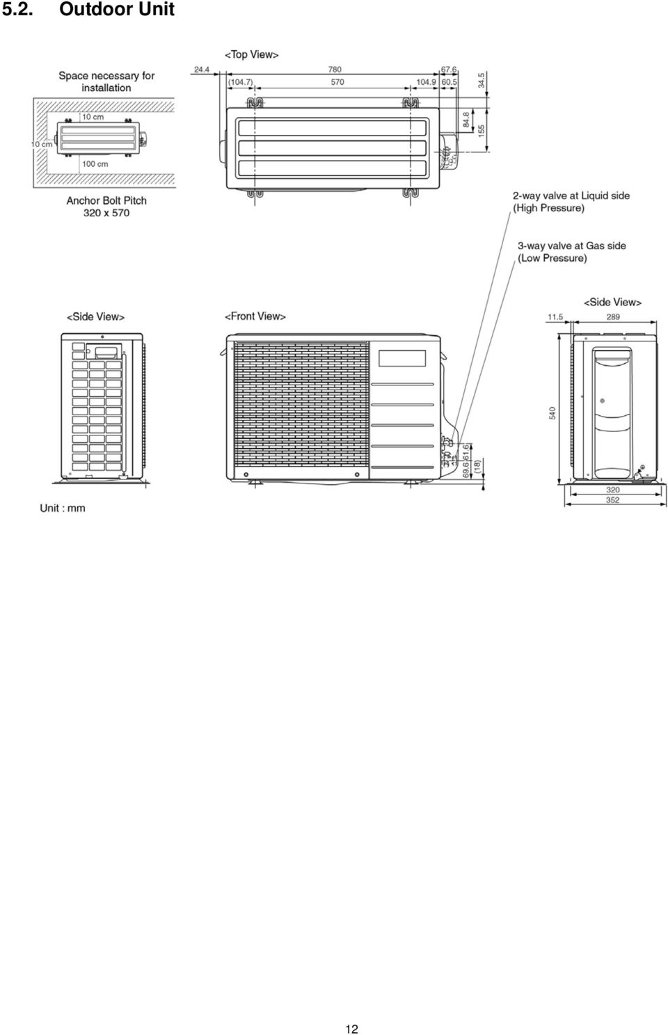
12 5.2. Outdoor Unit 12
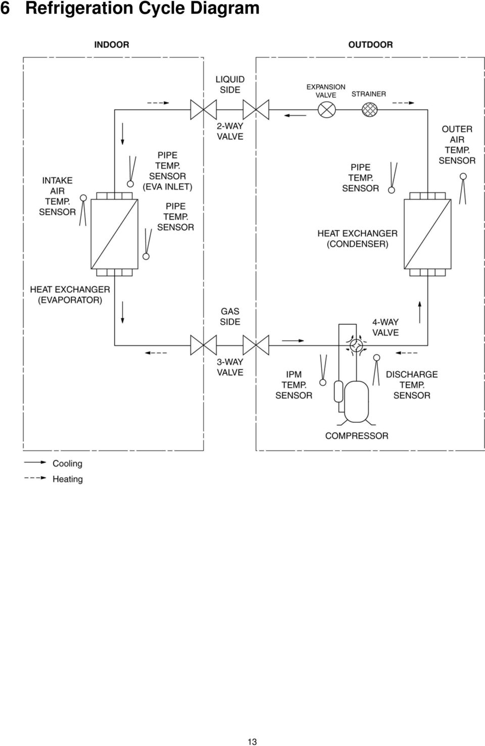
13 6 Refrigeration Cycle Diagram 13
14 7 Block Diagram 14

15 8 Wiring Connection Diagram 8.1. Indoor Unit 15

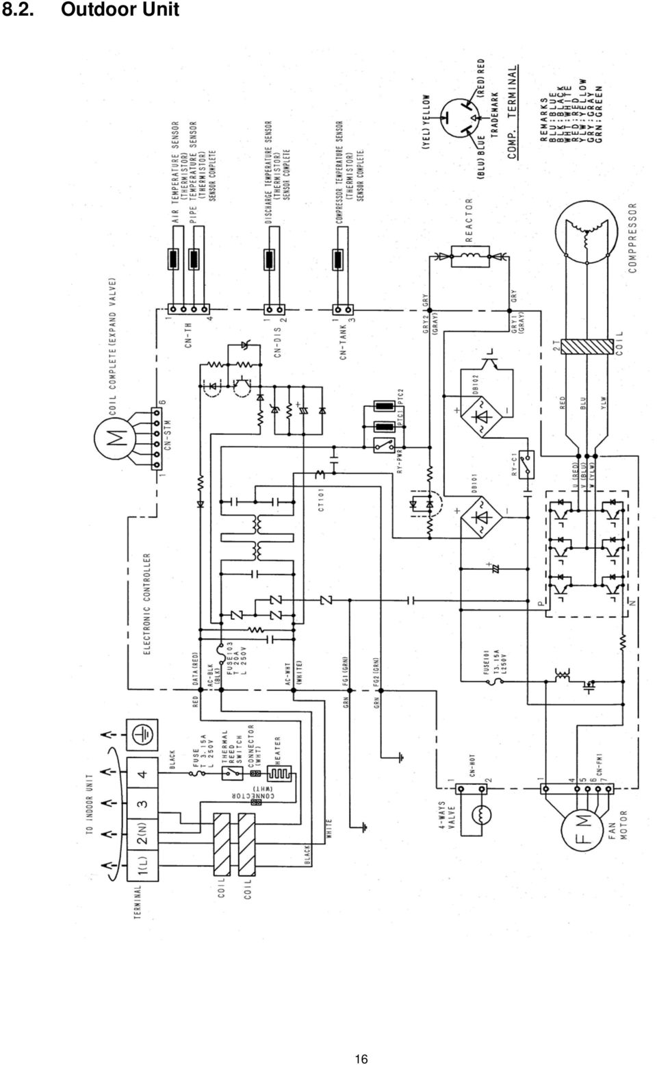
16 8.2. Outdoor Unit 16
17 9 Printed Circuit Board 9.1. Indoor Unit TOP VIEW 17

18 BOTTOM VIEW 18

19 9.2. Indicator TOP VIEW BOTTOM VIEW 19

20 9.3. Diagnosis TOP VIEW BOTTOM VIEW 20

21 9.4. Outdoor Unit TOP VIEW 21
22 BOTTOM VIEW 22
23 10 Installation Instruction Select The Best Location Indoor Unit Indoor/Outdoor Unit Installation Diagram There should not be any heat source or steam near the unit. There should not be any obstacles blocking the air circulation. A place where air circulation in the room is good. A place where drainage can be easily done. A place where noise prevention is taken into consideration. Do not install the unit near the door way. Ensure the spaces indicated by arrows from the wall, ceiling, fence or other obstacles. Recommended installation height for indoor unit shall be at least 2.5 m. Outdoor Unit If an awning is built over the unit to prevent direct sunlight or rain, be careful that heat radiation from the condenser is not obstructed. There should not be any animal or plant which could be affected by hot air discharged. Keep the spaces indicated by arrows from wall, ceiling, fence or other obstacles. Do not place any obstacles which may cause a short circuit of the discharged air. If piping length is over the rated length, additional refrigerant should be added as shown in the table. Piping size Model Gas Liquid Rated Length (m) Max Elevation (m) Max. Piping Length (m) Additional Refrigerant (g/m) XE9EKE 3/8 1/ XE12EKE 1/2 1/ This illustration is for explanation purposes only. The indoor unit will actually face a different way. 23
24 10.2. Indoor Unit How To Fix Installation Plate The mounting wall is strong and solid enough to prevent it from the vibration. The centre of installation plate should be at more than 485 mm at right and left of the wall. The distance from installation plate edge to ceiling should more than 75mm. From installation plate left edge to unit's left side is 75 mm. From installation plate right edge to unit's right is 85 mm. : For left side piping, piping connection for liquid should be about 5 mm from this line. 2. Drill the piping plate hole with ø70 mm hole-core drill. Line according to the left and right side edge of the installation plate. The meeting point of the extended line is the centre of the hole. Another method is by putting measuring tape at position as shown in the diagram above. The hole centre is obtained by measuring the distance namely 107 mm and 58 mm for left and right edge of the installation plate respectively. Drill the piping hole at either the right or the left and the hole should be slightly slanted to the outdoor side To Drill A Hole In The Wall And Install A Sleeve Of Piping 1. Insert the piping sleeve to the hole. 2. Cut the sleeve until it extrudes about 15 mm from the wall. Caution When the wall is hollow, please be sure to use the sleeve for tube ass y to prevent dangers caused by mice biting the connecting cable. 3. Fix the bushing to the sleeve. 4. Finish by sealing the sleeve with putty or caulking compound at the final stage. : : For left side piping, piping connection for gas should be about 55 mm from this line. For left side piping, piping connection cable should be about 750 mm from this line. 1. Mount the installation plate on the wall with 5 screws or more. (If mounting the unit on the concrete wall, consider using anchor bolts.) Always mount the installation plate horizontally by aligning the marking-off line with the thread and using a level gauge Installing The Ventilation Hose Carry out work carefully not to scratch the surface of the mobile panel. Attached accessories Ventilation hose connection diagram 24
25 When using the extension ventilation hose (optional) Indoor Unit Installation For the right rear piping 1. Removing the bottom left corner For the right and right bottom piping 2. Connecting and fixing the ventilation hose to the ventilation hole of the unit 3. Keep the ventilation hose behind the chassis of the unit (in case installing in the rear right, right and bottom right) 25
26 For the embedded piping 2. Install the Indoor Unit 3. Secure the Indoor Unit 4. Insert the connecting cable 1. Pull out the piping and drain hose 26
27 5. Treating methods of the end of the ventilation hose (This can be used for left rear piping & left bottom piping also.) 27
28 Connect The Cable To The Indoor Unit 1. The inside and outside connecting cable can be connected without removing the front grille. 2. Connecting cable between indoor unit and outdoor unit shall be approved polychloroprene sheathed mm 2 flexible cord, type designation 245 IEC 57 or heavier cord. Ensure the color of wires of outdoor unit and the terminal Nos. are the same to the indoor s respectively. Earth lead wire shall be longer than the other lead wires as shown in the figure for the electrical safety in case of the slipping out of the cord from the anchorage Connecting The Piping Connecting The Piping To Indoor Unit Please make flare after inserting flare nut (locate at joint portion of tube assembly) onto the copper pipe. (In case of using long piping) Connect the piping Align the center of piping and sufficiently tighten the flare nut with fingers. Further tighten the flare nut with torque wrench in specified torque as stated in the table. Secure the cable onto the control board with the holder (clamper). Model Piping size (Torque) Gas Liquid XE9EKE 3/8 [42 N m] 1/4 [18 N m] XE12EKE 1/2 [55 N m] 1/4 [18 N m] Connecting The Piping To Outdoor Unit Decide piping length and then cut by using pipe cutter. Remove burrs from cut edge. Make flare after inserting the flare nut (locate at valve) onto the copper pipe. Align center of piping to valves and then tighten with torque wrench to the specified torque as stated in the table. CUTTING AND FLARING THE PIPING 1. Please cut using pipe cutter and then remove the burrs. 2. Remove the burrs by using reamer. If burrs is not removed, gas leakage may be caused. Turn the piping end down to avoid the metal powder entering the pipe. 3. Please make flare after inserting the flare nut onto the copper pipes Outdoor Unit Install The Outdoor Unit After selecting the best location, start installation according to Indoor/Outdoor Unit Installation Diagram. 1. Fix the unit on concrete or rigid frame firmly and horizontally by bolt nut (ø10 mm). 2. When installing at roof, please consider strong wind and earthquake. Please fasten the installation stand firmly with bolt or nails. 28
29 Evacuation Of The Equipment (For Europe & Oceania Destination) WHEN INSTALLING AN AIR CONDITIONER, BE SURE TO EVACUATE THE AIR INSIDE THE INDOOR UNIT AND PIPES in the following procedure. 1. Connect a charging hose with a push pin to the Low and High side of a charging set and the service port of the 3-way valve. Be sure to connect the end of the charging hose with the push pin to the service port. 2. Connect the center hose of the charging set to a vacuum pump with check valve, or vacuum pump and vacuum pump adaptor. 3. Turn on the power switch of the vacuum pump and make sure that the needle in the gauge moves from 0 cmhg (0 MPa) to - 76 cmhg (-0.1 MPa). Then evacuate the air approximately ten minutes. 4. Close the Low side valve of the charging set and turn off the vacuum pump. Make sure that the needle in the gauge does not move after approximately five minutes. Note: BE SURE TO FOLLOW THIS PROCEDURE IN ORDER TO AVOID REFRIG- ERANT GAS LEAKAGE. 5. Disconnect the charging hose from the vacuum pump and from the service port of the 3-way valve. 6. Tighten the service port caps of the 3-way valve at torque of 18 N.m with a torque wrench. 7. Remove the valve caps of both of the 2-way valve and 3-way valve. Position both of the valves to OPEN using a hexagonal wrench (4 mm). 8. Mount valve caps onto the 2-way valve and the 3-way valve. Be sure to check for gas leakage. CAUTION If gauge needle does not move from 0 cmhg (0 MPa) to -76 cmhg (-0.1 MPa), in step 3 above take the following measure: If the leak stops when the piping connections are tightened further, continue working from step 3. If the leak does not stop when the connections are retightened, repair the location of leak. Do not release refrigerant during piping work for installation and reinstallation. Take care of the liquid refrigerant, it may cause frostbite. 29
30 Connect The Cable To The Outdoor Unit 1. Remove the control board cover from the unit by loosening the screw. 2. Connecting cable between indoor unit and outdoor unit shall be approved polychloroprene sheathed 5 x 1.5 mm 2 flexible cord, type designation 245 IEC 57 or heavier cord. 3. Secure the cable onto the control board with the holder (clamper). 4. Attach the control board cover back to the original position with the screw. 30
31 11 Operation and Function Basic Function Inverter control, which equipped with a microcomputer in determining the most suitable operating mode as time passes, automatically adjusts output power for maximum comfort always. In order to achieve the suitable operating mode, the microcomputer maintains the set temperature by measuring the temperature of the environment and performing temperature shifting. The compressor at outdoor unit is operating following the frequency instructed by the microcomputer at indoor unit that judging the condition according to internal setting temperature and intake air temperature Internal Setting Temperature Once the operation starts, remote control setting temperature will be taken as base value for temperature shifting processes. These shifting processes are depending on the air conditioner settings and the operation environment. The final shifted value will be used as internal setting temperature and it is updated continuously whenever the electrical power is supplied to the unit Airflow Direction 1. There are two types of airflow, vertical airflow (directed by horizontal vane) and horizontal airflow (directed by vertical vanes). 2. Control of airflow direction can be automatic (angles of direction is determined by operation mode, heat exchanger temperature and intake air temperature) and manual (angles of direction can be adjusted using remote control) Vertical Airflow Operation Mode Airflow Direction Vane Angle ( ) Heating Auto with Heat Exchanger A Upward fix 3 Temperature B Downward fix 64 C Upward fix 3 D Downward fix 3 Manual Cooling, Soft Dry Auto 8 ~ 36 Manual Mode Judgement in Auto Auto 8 Manual Automatic vertical airflow direction can be set using remote control; the vane swings up and down within the angles as stated above. For heating mode operation, the angle of the vane depends on the indoor heat exchanger temperature as Figure 1 below. When the air conditioner is stopped using remote control, the vane will shift to close position. 2. Manual vertical airflow direction can be set using remote control; the angles of the vane are as stated above and the positions of the vane are as Figure 2 below. When the air conditioner is stopped using remote control, the vane will shift to close position. 31
32 Horizontal Airflow 1. Automatic horizontal airflow direction can be set using remote control; the vane swings left and right within the angles as stated below. For heating mode operation, the angle of the vane depends on the indoor heat exchanger temperature as Figure 1 below. Operation Mode Vane Angle ( ) Heating, with heat exchanger temperature A 65 ~ 115 B 90 Cooling, Soft Dry and Ion 65 ~ Manual horizontal airflow direction can be set using remote control; the angles of the vane are as stated below and the positions of the vane are as Figure 2 above. Pattern Airflow Direction Pattern at Remote Control Vane Angle ( ) Quiet operation (Cooling Mode/Cooling area of Dry Mode) A. Purpose To provide quiet cooling operation compare to normal operation. B. Control condition a. Quiet operation start condition When quiet button at remote control is pressed. Quiet LED illuminates. b. Quiet operation stop condition 1. When one of the following conditions is satisfied, quiet operation stops: a. Powerful button is pressed. b. Stop by OFF/ON switch. c. Timer off activates. d. Quiet button is pressed again. 32
33 2. When quiet operation is stopped, operation is shifted to normal operation with previous setting. 3. When fan speed is changed, quiet operation is shifted to quiet operation of the new fan speed. 4. When operation mode is changed, quiet operation is shifted to quiet operation of the new mode. 5. During quiet operation, if timer on activates, quiet operation maintains. 6. After off, when on back, quiet operation is not memorised. C. Control contents 1. Fan speed is changed from normal setting to quiet setting of respective fan speed. This is to reduce sound of Hi, Me, Lo for 3dB. 2. Fan speed for quiet operation is -1 step from setting fan speed Quiet operation (Heating) A. Purpose To provide quiet heating operation compare to normal operation. B. Control condition a. Quiet operation start condition When quiet button at remote control is pressed. Quiet LED illuminates. b. Quiet operation stop condition 1. When one of the following conditions is satisfied, quiet operation stops: a. Powerful button is pressed. b. Stop by OFF/ON switch. c. Timer off activates. d. Quiet button is pressed again. 2. When quiet operation is stopped, operation is shifted to normal operation with previous setting. 3. When fan speed is changed, quiet operation is shifted to quiet operation of the new fan speed. 4. When operation mode is changed, quiet operation is shifted to quiet operation of the new mode, except fan only mode. 5. During quiet operation, if timer on activates, quiet operation maintains. 6. After off, when on back, quiet operation is not memorised. C. Control contents a. Fan Speed manual 1. Fan speed is changed from normal setting to quiet setting of respective fan speed. This is to reduce sound of Hi, Me, Lo for 3dB. 2. Fan speed for quiet operation is -1 step from setting fan speed. 3. Fan Speed Auto Indoor FM RPM depends on pipe temp sensor of indoor heat exchanger Powerful Mode Operation When the powerful mode is selected, the internal setting temperature will shift to achieve the setting temperature quickly. (a) Cooling Operation 33
34 (b) Soft Dry Operation (c) Heating Operation ON Timer Control ON timer can be set using remote control, the unit with timer set will start operate earlier than the setting time. This is to provide a comfortable environment when reaching the set ON time. 60 minutes before the set time, indoor (at fan speed of Lo-) and outdoor fan motor start operate for 30 seconds to determine the indoor intake air temperature and outdoor air temperature in order to judge the operation starting time. From the above judgment, the decided operation will start operate earlier than the set time as shown below OFF Timer Control OFF timer can be set using remote control, the unit with timer set will stop operate at set time Auto Restart Control 1. When the power supply is cut off during the operation of air conditioner, the compressor will re-operate within three to four minutes (there are 60 patterns of compressor restart waiting time between 2 minutes 58 seconds and 3 minutes 52 seconds to be selected randomly) after power supply resumes. 2. This type of control is not applicable during ON/OFF Timer setting Remote Control Signal Receiving Sound Long beep sound will be heard when:- - Stopping the air conditioner using ON/OFF switch. Short beep sound will be heard for others setting. 34
35 11.9. Filter Cleaning Control Filter cleaning function helps to: - Clean the filters automatically on a regular basis. - Avoid airflow blockage caused by dusty filter. - Prevent growth of mold inside the unit. - Improve cooling effect that saves energy consumption. The dust trapped on the filters surface is sucked and discharged to outdoor by a ventilation motor. By default, filter cleaning will run automatically once the unit is turned off if the air conditioner: - Operates continuously for at least 2 hours and above, and - Accumulative operation time is at least 2 hours and above. The filter surface is divided into rows. Each cleaning cycle will clean one row at a time. The numbers of rows to be cleaned will be based on the air conditioner s accumulative operation time and model purchased. The following table is an example for model 1.5 HP. Accumulative operation time Number of cleaning cycle (<: less than) (1 cycle: < 4 minutes) < 2 hours 0 2 hours and < 6 hours 2 6 hours and < 9 hours 3 9 hours and < 12 hours 4 12 hours and < 15 hours 5 15 hours and < 18 hours 6 18 hours and < 21 hours 7 21 hours and < 24 hours 8 The number of cleaning cycle depends on the fan speed setting as well. The table above is an example when the fan speed setting is HI. The number of cleaning cycle will be lesser if the fan speed setting is lower. You can also set the filter cleaning manually. For details, see Timer Filter Cleaning and Manual Filter Cleaning Auto Filter Cleaning Filter cleaning will run automatically after the air conditioner operation stops when air conditioner is turned off using remote control or turned off by the air conditioner timer. After the filter cleaning is completed, the air conditioner operation will remain off. The filter cleaning indicator light will move to left or right when filter cleaning is in progress. Filter cleaning in progress will be cancelled if: - Certain buttons on the remote control are pressed. - The air conditioner main unit s movable front panel is lifted up. - There is a power failure Force Filter Cleaning Once the air conditioner operation time exceeds 24 hours, the unit is forced to run filter cleaning. After the filter cleaning is completed, the air conditioner operation will resume automatically Timer Filter Cleaning Filter cleaning timer can be set to run at a specified time daily, given that the air conditioner accumulative operation time is at least 30 minutes and above. Filter cleaning timer overrides air-conditioner s timer in any given setting. Once filter cleaning timer starts, air conditioner operation will stop. After the filter cleaning is completed, the air conditioner operation will resume automatically Manual Filter Cleaning Manual filter cleaning can be performed a comprehensive filter cleaning. A comprehensive filter cleaning may take less than an hour to complete. This operation has the highest priority over other operation modes. After the filter cleaning is completed, the air conditioner operation will resume automatically. 35
36 Ventilation Control To circulate the indoor air. The ventilation operation is enable by pressing the VENTILATION Button. (As a default setting, ventilation will be turned on automatically once the air conditioner operation starts) Simultaneous Operation Operates simultaneously with Auto/Cooling/Drying operation. Press VENTILATION button at remote control repeatedly to select your desired ventilation setting. Auto/Cooling/Drying operation remains as normal regardless of ventilation setting. When OFF/ON button at remote control is pressed, all of the air conditioner operations are turned off Independent Operation Ventilation operates independently. Ventilation can be turned on when the air conditioner is in non-operation mode. Fan speed in this setting remains as AUTO. Press OFF/ON button at remote control to turn off the ventilation operation. 36
37 12 Protection Control Time Delay Safety Control Compressor will not start for three minutes after stop of the operation Seconds Forced Operation Once compressor starts the operation, it will not stop its operation for 30 seconds. However, it can be stopped with the remote controller or the Auto button on the indoor unit Total Running Current Control 1. When the total running current exceeds l1, compressor operation frequency is reduced. If it reaches below l1, the operation frequency is increased. (But, up to programmed frequency.) 2. If total running current exceeds l2, compressor is stopped immediately. 3. If it happens three (3) times within 20 minutes, operation will be stopped and Timer LED blinks. ( F98 is activating.) Running current CS-XE9EKE CS-XE12EKE Cooling I1 3.7A 5.8A I2 25.0A 25.0A Heating I1 5.9A 8.2A I2 25.0A 25.0A IPM (Power transistor) Protection Control (DC Peak detection Abnormal Current Control If inverter load current (DC peak) exceeds a rated value, compressor will be stopped immediately. When the excess occurs within 30 seconds after operation, it restarts in 1 minute and when after 30 seconds, restarts in 2 minutes. If the excess continuously occurs 7 times within 30 minutes after compressor starts, the unit will be stopped and timer LED on the indoor unit will be blinking. ( F99 is to be confirmed.) IPM Overheating Prevention Control If temperature of IPM exceeds 103 C, compressor will be stopped. It will restart in 2 minutes. Temperature for restarting: 90 C. If the excess occurs 7 times within 30 minutes after compressor starts, the compressor will be stopped and timer LED on the indoor unit will be blinking. ( F96 is to be confirmed.) Compressor Overheating Prevention Control 1. If discharge pipe temperature exceeds 100 C, compressor power will be limited. 2. If discharge pipe temperature exceeds 112 C, compressor will be stopped. 3. If the above excess occurs 4 times per 10 minutes, timer LED will be blinking. ( F97 is to be confirmed.) Outdoor High Pressure Prevention Control (Cooling and Dry operations) 1. If outdoor heat exchanger temperature exceeds 63 C in cooling or dry operation, compressor will be stopped. 2. Timer LED is not blinking. ( F95 is memorized, then.) Compressor Protection Control (Refrigeration Cycle Abnormality) In cooling and Dry operations 1. When compressor is operated continuously for 5 minutes in the maximum cooling power: a running current of A and [Indoor intake air temperature] - [Indoor heat exchanger temperature] < 4 C, compressor will be stopped. 2. If the above excess occurs twice for 20 minutes, timer LED is to be blinking. ( F91 is to be confirmed.) In Heating operation 1. When compressor is operated continuously for 5 minutes in the rated heating power: a running current of A and [Indoor heat exchanger temperature] - [Indoor intake air temperature] < 5 C, compressor will be stopped. 2. If the above excess occurs twice for 20 minutes, timer LED is to be blinking. ( F91 is to be confirmed.) 37
38 12.8. Four-way Valve Operation Detection Control (Switching Abnormality between Cooling and Heating) In Cooling operation 1. When indoor heat exchanger temperature exceeds 45 C in 4 minutes after compressor starts, compressor will be stopped. 2. If the above excess occurs 4 times per 30 minutes, timer LED is to be blinking. ( F11 is to be confirmed.) In Heating operation 1. When indoor heat exchanger temperature is below 0 C in 4 minutes after compressor starts, compressor will be stopped. 2. If the above excess occurs 4 times per 30 minutes, timer LED is to be blinking. ( F11 is to be confirmed.) Anti-Freezing Control (Cooling and Dry operations) Limit of Cooling power 1. When temperature of indoor heat exchanger is below 5 C, operating frequency will be decreased. 2. When temperature of indoor heat exchanger exceeds 7 C, operating frequency will be increased. (But, up to programmed frequency.) 3. When temperature of indoor heat exchanger is below 0 C continuously for 6 minutes, compressor will be stopped. 4. Timer LED is not blinking. ( F99 is memorized, then.) Limit of Indoor fan speed When temperature of indoor heat exchanger is below 6 C (2 C at Dry) continuously for 6 minutes, indoor fan speed will be increased by 50 rpm Outdoor Air Temperature Control In Cooling and Dry operations 1. When outdoor air temperature is below 25 C, the maximum power will be limited up to about % of the rated power. 2. When outdoor air temperature is below 18 C, the maximum power will be limited up to about % of the rated power. 3. When outdoor air temperature is below 11 C, the maximum power will be limited up to about 26-81% of the rated power Indoor Intake Air Temperature Control (Heating operation) 1. When indoor air temperature is 35 C or more, the maximum power will be limited up to the rated power. 2. When fan speed is set at Lo and intake air temperature is below 21 C, the maximum power will be limited up to the rated power. 38
39 13 Servicing Mode Auto OFF/ON Button This button is used to pump down the air conditioner during servicing or transferring of outdoor unit. 1. It can be used to operate the air conditioner in limited function if remote control is misplaced or malfunction. Auto operation will start when Auto OFF/ON Button is pressed and released within 5 seconds. Within 5 minutes of each operation, if the Auto OFF/ON Button is pressed again for more than 5 seconds the air conditioner will switch to another operation after Beep sound. 2. The Auto OFF/ON Button may be used together with remote control to set / change the advanced setting of air conditioner operation. Press and hold AUTO OFF/ON Button for more than 5 seconds, the air conditioner always operate force cooling operation. Press and hold AUTO OFF/ON Button until 2 Beep sounds are heard, the forced heating operation is at standby condition. Press and hold AUTO OFF/ON Button until 3 Beep sounds are heard, the various setting mode is at standby condition. Press and hold AUTO OFF/ON Button until 4 Beep sounds are heard, the individual correspondence mode is at standby condition. During standby condition, when the indoor unit receives AC RESET signal (Beep sound is heard) from remote control, the corresponding mode will be activated. 39
40 13.2. Various Setting Mode Remote Control Number Switch Mode Set remote control number through receiving signal from remote control. (Please refer to Select Remote Control Transmission Code) Current Setting Choose the Current Setting by pressing AUTO OFF/ON button Ventilation Control Setting Mode Set the ventilation operation and auto filter cleaning operation by pressing Auto OFF/ON Button. * VENTILATION 1: Enable ventilation operation and auto filter cleaning. * VENTILATION 2: Disable ventilation operation and auto filter cleaning. * VENTILATION 3: Ventilation only and no filter cleaning. If there is no operation, or receives any remote control signal within 5 minutes, the setting mode quits. 40
41 Filter Cleaning Operation Setting Choose the operation setting by pressing AUTO OFF/ON button. Setting Operation 1 Filter cleaning will run automatically after the air conditioner operation stops (air conditioner is turned off using remote control). After the filter cleaning is completed, the air conditioner operation will remain off. 2** Filter cleaning will run automatically before the air conditioner operation starts (air conditioner is either turned on using remote control or turned on by the air conditioner timer). After the filter cleaning is completed, the air conditioner operation will start automatically. 3** Filter cleaning will run automatically before the air conditioner operation starts (air conditioner is turned on using remote control). After the filter cleaning is completed, the air conditioner operation will start automatically. 4 Filter cleaning will run automatically after the air conditioner operation stops (air conditioner is either turned off using remote control or turned off by the air conditioner timer). After the filter cleaning is completed, the air conditioner operation will remain off. ** The setting is valid only if the following conditions are fulfilled: 1. The air conditioner is turned off for at least 3 minutes. 2. The air conditioner has operated continuously for at least 2 hours in previous operation. If there is no operation, or receives any remote control signal within 5 minutes, the setting mode quits Individual Correspondence Mode 41
42 During Receiving Sound ON/OFF setting mode, press AUTO OFF/ON Button to toggle the Receiving sound. During H14 Abnormal Detection Selection Mode, press AUTO OFF/ON Button to toggle the Abnormal detection. During Ventilation Quiet mode, press AUTO OFF/ON Button to toggle the Ventilation setting. During Auto Filter Cleaning cancellation setting mode, press AUTO OFF/ON Button to toggle the Auto Filter Cleaning cancellation setting. If there is no operation, or receives any remote control signal within 5 minutes, the setting mode quits Select Remote Control Transmission Code There are 4 type of remote control transmission code could be selected and stored in EEPROM of indoor unit. The indoor unit will only operate when received signal with same transmission code from remote control. This could prevent signal interference when there are 2 or more indoor unit installed nearby together. To change remote control transmission code, short or open jumpers at the remote control printed circuit board. Remote Control Printed Circuit Board Transmission Code Combination J - A J - B Remote Control No. Short Open A (Default) Open Open B Short Short C Open Short D Under various setting mode, after select the transmission code combination of remote control, press any button of remote control to transmit a signal to indoor unit. The transmission code will be stored in EEPROM. After signal is received, the various setting mode is cancelled and return to normal operation. 42
43 14 Demo Mode The purpose of Demo Mode is to demonstrate the filter cleaning function. The Demo Mode can be activated by using AUTO OFF/ON button. The Demo Mode is activated by AUTO OFF/ON button. (Beep 4) The Demo Mode activation does not start the demonstration. The demonstration starts after received remote control ON signal. Demo operation: Zone A - Normal operation (follow remote control setting) for 2 minutes. Zone B a. Filter cleaning operation for 1 round-trip. b. Then return to normal operation. (Auto Swing operates but Indoor Fan stops) After step b. operates for 11 minutes, return to step a. During step b. when cleaning button is pressed, return to step a. During demonstration, if other remote control button (Except ON/OFF button) is pressed, the demo operation return to (Zone A). The demonstration stop after received remote control OFF signal. Demo Mode is deactivated by AUTO OFF/ON button. (Beep 3, then long Beep 1) 43
44 15 Troubleshooting Guide Refrigeration Cycle System In order to diagnose malfunctions, make sure that there are no electrical problems before inspecting the refrigeration cycle. Such problems include insufficient insulation, problem with the power source, malfunction of a compressor and a fan. The normal outlet air temperature and pressure of the refrigeration cycle depends on various conditions, the standard values for them are shown in the table to the right. 44
45 15.2. Relationship Between The Condition of The Air Conditioner and Pressure and Electric Current Cooling Mode Condition of the air conditioner Low Pressure High Pressure Electric current during operation Heating Mode Low Pressure High Pressure Electric current during operation Insufficient refrigerant (gas leakage) Clogged capillary tube or Strainer Short circuit in the indoor unit Heat radiation deficiency of the outdoor unit Inefficient compression Carry out the measurements of pressure, electric current, and temperature fifteen minutes after an operation is started. 45
CS-CE9NKE CS-CE12NKE CU-CE9NKE CU-CE12NKE TABLE OF CONTENTS WARNING
 Order No: PAPAMY1207094CE Indoor Unit CS-CE9NKE CS-CE12NKE Outdoor Unit CU-CE9NKE CU-CE12NKE WARNING This service information is designed for experienced repair technicians only and is not designed for
CU-2E15LBE CU-2E18LBE CU-3E18LBE CU-4E23LBE
 Order No. PHAAM1003090C3 Outdoor Unit CU-2E15LBE CU-2E18LBE CU-3E18LBE CU-4E23LBE Air Conditioner Please file and use this manual together with the service manual for Model No. CS-E7LKEW CU-E7LKE CS-E7LKEW
TABLE OF CONTENTS. Air Conditioner. Indoor Unit Outdoor Unit CS-NE9MKE CU-NE9MKE CS-NE12MKE CU-NE12MKE CS-XE9MKE-5 CU-NE9MKE CS-XE12MKE-5 CU-NE12MKE
 Order No. PHAAM1107134C2 Air Conditioner Indoor Unit Outdoor Unit CS-NE9MKE CU-NE9MKE CS-NE12MKE CU-NE12MKE CS-XE9MKE-5 CU-NE9MKE CS-XE12MKE-5 CU-NE12MKE TABLE OF CONTENTS PAGE 1 Safety Precautions-----------------------------------------------
CU-S9KKQ CU-S12KKQ CU-S18KKQ CU-S24KKQ CS-S9KKQ CS-S12KKQ CS-S18KKQ CS-S24KKQ WARNING
 Order No: PHAAM1001037C3 Indoor Unit CS-S9KKQ CS-S12KKQ CS-S18KKQ CS-S24KKQ Outdoor Unit CU-S9KKQ CU-S12KKQ CU-S18KKQ CU-S24KKQ WARNING This service information is designed for experienced repair technicians
CS-HE9NKE CS-HE12NKE CS-AE9NKE CU-HE9NKE CU-HE12NKE CU-AE9NKE TABLE OF CONTENTS WARNING
 Order No: PAPAMY1207093CE Indoor Unit CS-HE9NKE CS-HE12NKE CS-AE9NKE Outdoor Unit CU-HE9NKE CU-HE12NKE CU-AE9NKE WARNING This service information is designed for experienced repair technicians only and
14. Troubleshooting Guide
 14. Guide 14.1 Refrigeration Cycle System In order to diagnose malfunctions, ensure the air conditioner is free from electrical problems before inspecting the refrigeration cycle. Such problems include
Split-type Air-Conditioner INSTALLATION MANUAL CONTENTS FOR INSTALLER MXZ-3A30NA MXZ-4A36NA ATTENTION. English. Français. Español
 Split-type Air-Conditioner MXZ-3A30NA MXZ-4A36NA INSTALLATION MANUAL Refer to the installation manual of each indoor unit for indoor unit installation. English Français Español ATTENTION This manual mentions
TECHNICAL DATA & SERVICE MANUAL SPLIT SYSTEM AIR CONDITIONER INDOOR UNIT: AW52AL AW64AL AW52AL 387030095 AW64AL 0.8180.463.0 07/05
 TECHNICAL DATA & SERVICE MANUAL INDOOR UNIT: AW52AL AW64AL SPLIT SYSTEM AIR CONDITIONER Model No. Product Code No. AW52AL 387030095 AW64AL 387030096 0.8180.463.0 07/05 IMPORTANT! Please read before installation
Air Conditioner CONTENTS CS-TE9DKE CU-TE9DKE CS-TE12DKE CU-TE12DKE. Order No. RAC0502005C2
 Order No. RAC0502005C2 Air Conditioner CS-TE9DKE CU-TE9DKE CS-TE12DKE CU-TE12DKE CONTENTS Page Page 1 Features 2 2 Functions 3 2.1. Remote Control 3 2.2. Indoor Unit 4 2.3. Outdoor unit 5 3 Product Specifications
Air Conditioner CU-XE9PKUA CU-XE12PKUA CS-XE9PKUA CS-XE12PKUA. Destination U.S.A. Canada WARNING
 Order No: PAPAMY1305056CE Air Conditioner Indoor Unit CS-XE9PKUA CS-XE12PKUA Outdoor Unit CU-XE9PKUA CU-XE12PKUA Destination U.S.A. Canada WARNING This service information is designed for experienced repair
TABLE OF CONTENTS. Air Conditioner CS-E9HKEA CU-E9HKEA CS-E12HKEA CU-E12HKEA
 Order No. MAC0801090C2 Air Conditioner CS-E9HKEA CU-E9HKEA CS-E12HKEA CU-E12HKEA TABLE OF CONTENTS PAGE 1 Safety Precaution ------------------------------------------------ 2 2 Specifications -----------------------------------------------------
AIR-CONDITIONER SPLIT TYPE
 FILE NO. A08-016 SERVICE MANUAL AIR-CONDITIONER SPLIT TYPE RAS-M10PKVP-E, RAS-M13PKVP-E, RAS-M16PKVP-E, RAS-M18PKVP-E / RAS-M10PKVP-ND, RAS-M13PKVP-ND, RAS-M16PKVP-ND, RAS-M18PKVP-ND / RAS-3M26GAV-E1,
Air Conditioner CONTENTS CS-V7DKE CU-V7DKE CS-V9DKE CU-V9DKE CS-V12DKE CU-V12DKE. Order No. MAC0412062C2
 Order No. MAC0412062C2 CS-V7DKE CU-V7DKE CS-V9DKE CU-V9DKE CS-V12DKE CU-V12DKE Air Conditioner CONTENTS Page Page 1 Features 3 2 Functions 4 2.1. Remote Control 4 2.2. Indoor Unit 5 2.3. Outdoor Unit 6
WH-UD09CE8 WH-UD12CE8 WH-UD14CE8 WH-UD16CE8 WH-SDF09C3E8 WH-SDF12C9E8 WH-SDF14C9E8 WH-SDF16C9E8 WARNING
 Order No. PHAAM1009094C2 Indoor Unit WH-SDF09C3E8 WH-SDF12C9E8 WH-SDF14C9E8 WH-SDF16C9E8 Outdoor Unit WH-UD09CE8 WH-UD12CE8 WH-UD14CE8 WH-UD16CE8 WARNING This service information is designed for experienced
Operating Instructions Air Conditioner
 F566272 Operating Instructions Air Conditioner CS-C18FFH CS-C28FFH CU-C18FFH CU-C28FFH ENGLISH Before operating the unit, read these operating instructions thoroughly and keep them for future reference.
SERVICE MANUAL SPLIT SYSTEM ROOM AIR CONDITIONER SHARP CORPORATION SHARP CORPORATION CONTENTS
 SERVICE MANUAL SPLIT SYSTEM ROOM AIR CONDITIONER INDOOR UNIT AH-129 AH-MP14 OUTDOOR UNIT AU-129 AU-MP14 CONTENTS SPECIFICATIONS...2 EXTERNAL DIMENSIONS...4 WIRING DIAGRAMS...5 ELECTRICAL PARTS...6 MICROCOMPUTER
SERVICE MANUAL. Room Air Conditioner Multi Split Wall-Mounted Type Indoor. FSAI-Pro-91AE2 FSAI-Pro-121AE2 FSAIF-Pro-181AE2
 SERVICE MANUAL Room Air Conditioner Multi Split Wall-Mounted Type Indoor FSAI-Pro-91AE2 FSAI-Pro-121AE2 FSAIF-Pro-181AE2 NOTE: Before servicing the unit, please read this at first. Always contact with
Floor Type Air-Conditioner INSTALLATION MANUAL CONTENTS FOR INSTALLER MFZ-KA25VA MFZ-KA35VA MFZ-KA50VA. English
 Floor Type Air-Conditioner MFZ-KA25VA MFZ-KA35VA MFZ-KA50VA INSTALLATION MANUAL This manual only describes the installation of indoor unit. When installing the outdoor unit, refer to the installation manual
USER INSTRUCTIONS FOR GET PORTABLE 12k BTU AIR CONDITIONER MODEL No. GPACU12HR
 USER INSTRUCTIONS FOR GET PORTABLE 12k BTU AIR CONDITIONER MODEL No. GPACU12HR CONTENTS Introduction Safety Notes Identification of parts Installation instructions Operation instructions Maintenance Troubleshooting
ROOM AIR CONDITIONER INSTALLATION MANUAL
 ROOM AIR CONDITIONER INSTALLATION MANUAL ( Split Type) Please read this installation manual completely before installing the product When the power cord is damaged, replacement work shall be performed
Dehumidifier Users manual. For Models: DH45S DH65S
 Dehumidifier Users manual For Models: DH45S DH65S 950-0062-revD Jan. 9 2007 FORWARD The appearance of the units that you purchase might be slightly different from the ones described in the Manual, but
Portable Air Conditioner
 Portable Air Conditioner Owner's Manual Model:3 in 1 12,000 Btu/h Series 3 Please read this owner s manual carefully before operation and retain it for future reference. CONTENTS 1. SUMMARY...1 2. PORTABLE
USER S MANUAL HSC-24A
 AIRREX AIR CONDITIONER USER S MANUAL HSC-24A Thank you for purchasing an AIRREX AIR CONDITIONER. BEFORE operation please read this user s manual carefully. Keep this manual readily available. It is ESSENTIAL
Wall Mounted Mini Split Heat Pump Air Conditioner
 Wall Mounted Mini Split Heat Pump Air Conditioner OPERATING AND INSTALLATION MANUAL Model: KFIHP-09-ID / KFHIP-09-OD KFHHP-12-ID / KFHHP-12-OD Indoor Unit. Outdoor Unit. Thank you for selecting Soleus
Use and Care Manual. Model CPA12KH AIR CONDITIONER
 Use and Care Manual Model CPA12KH AIR CONDITIONER Introduction Thank you for choosing this air conditioner to provide you and your family with all of the "Home Comfort" requirements for your home, cottage
CONTENTS 1. IMPORTANT NOTICE 2 2. TECHNICAL SPECIFICATION 3 3. OPERATION DETAILS 4 4. WIRING DIAGRAM 11 5. EXPLOSION VIEW 12 6.
 TCL WALL MOUNTED SPLIT-TYPE AIR CONDITIONERS SERVICE MANUAL No.TE051220 Models TAC-09CHSA/GI TAC-12CHSA/GI CONTENTS 1. IMPORTANT NOTICE 2 2. TECHNICAL SPECIFICATION 3 3. OPERATION DETAILS 4 4. WIRING DIAGRAM
CONTENTS 1. IMPORTANT NOTICE 2 2. TECHNICAL SPECIFICATION 3 3. OPERATION DETAILS 4 4. ELECTRICAL SCHEMATIC DIAGRAM 13 5. EXPLOSION VIEW 16 6
 TCL WALL MOUNTED SPLIT-TYPE AIR CONDITIONERS SERVICE MANUAL No.TE080528 Models KFTHP-12 KFTHP-18 KFTHP-24 CONTENTS 1. IMPORTANT NOTICE 2 2. TECHNICAL SPECIFICATION 3 3. OPERATION DETAILS 4 4. ELECTRICAL
SPLIT -TYPE ROOM AIR CONDITIONER
 Before using your air conditioner, please read this manual carefully and keep it for future reference SPLIT -TYPE ROOM AIR CONDITIONER Please read this installation manual completely before installing
SWIMMING POOL HEAT PUMP
 SWIMMING POOL HEAT PUMP Installation & User Manual Model HP40B HP50B HP65B Hayward Pool Products Canada, Inc. T: 1-888-238-7665 www.haywardpool.ca CONTENT I. Application 4 II. Features 4 III. Technical
CS-PE9CKE CU-PE9CKE CS-PE12CKE CU-PE12CKE
 Order No. GMAC0401003C2 CS-PE9CKE CU-PE9CKE CS-PE12CKE CU-PE12CKE Room Air Conditioners CONTENTS Page 1 Functions 2 2 Product Specifications 5 3 Dimensions 9 4 Refrigeration Cycle Diagram 11 5 Block Diagram
WINDOW ROOM AIR CONDITIONER
 WINDOW ROOM AIR CONDITIONER Installation and Operation Manual Electromechanical Remote Control CAPACITIES 220V - 60 HZ. 12,000; 18,000; 24000 BTU/HR 220V-240V - 50 HZ. 12,000; 18,000; 24000 BTU/HR Please
USER S MANUAL FH052EAV1 FH070EAV1. System Air Conditioner (Cooling and Heating) ENGLISH ESPAÑOL FRANÇAIS ITALIANO PORTUGUÊS DEUTSCH E HNIKA
 ENGLISH ESPAÑOL FRANÇAIS ITALIANO PORTUGUÊS DEUTSCH E HNIKA") USER S MANUAL FH052EAV1 FH070EAV1 E HNIKA PORTUGUÊS ENGLISH ESPAÑOL ITALIANO DEUTSCH FRANÇAIS System Air Conditioner (Cooling and Heating) E S F I P D G DB98-29263A(1) Safety Precautions Register your
USER S MANUAL FH052EAV1 FH070EAV1 E HNIKA PORTUGUÊS ENGLISH ESPAÑOL ITALIANO DEUTSCH FRANÇAIS System Air Conditioner (Cooling and Heating) E S F I P D G DB98-29263A(1) Safety Precautions Register your
HP switch LP switch Discharge thermo Comp. Surface thermo
 1 Specifications Zubadan Model Name PUHZ-SHW80VHA PUHZ-SHW11VHA PUHZ-SHW11YHA Power supply (phase, cycle, voltage) 1φ, V, Hz 1φ, V, Hz 3φ, 0V, Hz Max. current A 9.5 35.0 13.0 Breaker size A 3 16 Outer
LG Floor Standing Type Air Conditioner INSTALLATION MANUAL
 website http://www.lgservice.com e-mail http://www.lgeservice.com/techsup.html LG Floor Standing Type Air Conditioner INSTALLATION MANUAL LG IMPORTANT Please read this installation manual completely before
TECHNICAL & SERVICE MANUAL WINDOW TYPE AIR CONDITIONER SA 79G SA 99G FILE NO. SA 79G SA 99G REFERENCE NO. SM700402
 TECHNICAL & SERVICE MANUAL SA 79G SA 99G FILE NO. WINDOW TYPE AIR CONDITIONER Model No. Product Code No. Destination SA-79G-A 1 851 005 18 General (50Hz) & Europe SA-99G-A 1 851 005 19 SA 79G SA 99G REFERENCE
Operating Instructions Split System Air Conditioner
 Operating Instructions Split System Air Conditioner Model No. Indoor Unit Type Indoor Unit Type Nominal Capacity 26 36 F2 Low Silhouette Ducted S-26PF2U6 S-36PF2U6 Connectable outdoor unit lineup This
Si10-417_C. Pocket Manual. Service Diagnosis SPLIT & MULTI
 Pocket Manual Service Diagnosis SPLIT & MULTI Service Diagnosis SPLIT & MULTI 1. Troubleshooting with LED...5 1.1 Indoor Unit... 5 1.2 Outdoor Unit... 10 2. Troubleshooting by Symptoms...11 2.1 Air conditioner
Split Type Room Air Conditioner. KSWM units
 OWNER S MANUAL Split Type Room Air Conditioner KSWM units Please read the operating instructions and safety precautions carefully and thoroughly before installing and operating your room air conditioner.
Service manual. Website: www.andico.com.au CAUTION - BEFORE SERVICING THE UNIT, READ THE SAFETY - PRECAUTIONS IN THIS MANUAL.
 Website: www.andico.com.au Service manual CAUTION - BEFORE SERVICING THE UNIT, READ THE SAFETY - PRECAUTIONS IN THIS MANUAL. - ONLY FOR AUTHORISED SERVICE PERSONNEL. MODELS: MPK1-09CR-QB8 MPK1-12ER-QB6
Portable Air Conditioner. OWNER S MANUAL Read these instructions before use. Model: MM14CCS. Voltage rating: 115V~60Hz Power rating : 1400W
 Portable Air Conditioner OWNER S MANUAL Read these instructions before use Model: MM14CCS Customer Support : 1-800-474-2147 Voltage rating: 115V~60Hz Power rating : 1400W For product inquiries or support
Portable Air Conditioner. OWNER S MANUAL Read these instructions before use. Model: MN12CES / MN10CESWW
 Portable Air Conditioner OWNER S MANUAL Read these instructions before use 8 Model: MN12CES / MN10CESWW Voltage rating: 120V~60Hz Power rating : 1100W (MN12CES) Power rating : 900W (MN10CESWW) Customer
OPTIONAL SLENDER REMOTE CONTROL
 DAIKIN ROOM AIR CONDITIONER Operation Manual OPTIONAL SLENDER REMOTE CONTROL BRC944A2B READ BEFORE OPERATION Safety Precautions...2 Names of Functions of Parts...4 Preparation before Operation...5 OPERATION
AIR CONDITIONER INSTALLATION MANUAL
 INSTALLATION MANUAL AIR CONDITIONER Please read this installation manual completely before installing the product. Installation work must be performed in accordance with the national wiring standards by
SERVICE INSTRUCTION R410A. WALL MOUNTEDtype INVERTER SPLIT TYPE ROOM AIR CONDITIONER. Models Indoor unit Outdoor unit
 SERVICE INSTRUCTION SPLIT TYPE ROOM AIR CONDITIONER WALL MOUNTEDtype INVERTER Models Indoor unit Outdoor unit ASYG07LECA ASYG09LECA ASYG12LECA ASYG14LECA AOYG07LEC AOYG09LEC AOYG12LEC AOYG14LEC R410A CONTENTS
9ASNA-A1-1202 SERVICE MANUAL SENVILLE AIRCONDITIONER DC INVERTER SPLIT WALL-MOUNTED TYPE
 9ASNA-A1-1202 SERVICE MANUAL SENVILLE AIRCONDITIONER DC INVERTER SPLIT WALL-MOUNTED TYPE CONTENTS 1. Precaution... 1 1.1 Safety Precaution... 1 1.2 Warning... 1 2. Function... 6 3. Dimension... 9 3.1 Indoor
Portable Air Conditioner. OWNER S MANUAL Read these instructions before use. Model: MF08CESWW. Voltage rating: 115V~60Hz Power rating : 800W
 MODE ALARM Portable Air Conditioner OWNER S MANUAL Read these instructions before use 8 Model: MF08CESWW Voltage rating: 115V~60Hz Power rating : 800W Customer Support : 1-800-474-2147 For product inquiries
ENGLISH INSTRUCTION & INSTALLATION MANUAL DUCTLESS MINI SPLIT AIR CONDITIONING SYSTEMS
 ENGLISH INSTRUCTION & INSTALLATION MANUAL DUCTLESS MINI SPLIT AIR CONDITIONING SYSTEMS Céliera Corporation. All rights reserved. Unauthorized duplication, reproduction prohibited. CONTENTS SAFETY PRECAUTIONS...
york air-conditioning products Residential & VRF News 2015
 york air-conditioning products Residential & VRF News 2015 york air-conditioning products Catalogue Content Split Systems Pag. High wall High Efficiency Inverter YWHJZH 09 to 24 K 6 High wall Inverter
Reverse Cycle Inverter Split System Air Conditioner
 Reverse Cycle Inverter Split System Air Conditioner Model Number TAC-09CHSA/JAI5 INSTALLATION MANUAL Contents 03 Warranty Details 04 Welcome 05 General Safety Instructions 06 Product Overview 07 Selecting
NewAir AC-10100E / AC-10100H Portable Air Conditioner Owner s Manual PLEASE READ AND SAVE THESE INSTRUCTIONS
 NewAir AC-10100E / AC-10100H Portable Air Conditioner Owner s Manual PLEASE READ AND SAVE THESE INSTRUCTIONS ELECTRICAL SAFETY This appliance is for indoor use only. Always turn off the unit and unplug
Operating Instructions Air Conditioner
 P07-T10130 Operating Instructions Air Conditioner Indoor Unit CS-F24DD1E5 CS-F28DD1E5 CS-F34DD1E5 CS-F43DD1E5 CS-F50DD1E5 Outdoor Unit Inverter Model (HBE5 Series) CU-YL24HBE5 CU-YL28HBE5 CU-YL34HBE5 CU-YL43HBE5
Important Safeguards
 Table of Contents Important Safeguards...2 Product Layout...3 Preparing for Use...4 Air-conditioning without installation...4 Air-conditioning with installation...5 Control Panel...6 Operating from the
AIR CONDITIONER INSTALLATION MANUAL
 FRANCAIS ESPAÑOL INSTALLATION MANUAL AIR CONDITIONER Please read this installation manual completely before installing the product. Installation work must be performed in accordance with the national wiring
AIR CONDITIONER (SPLIT TYPE)
") OWNER S MANUAL AIR CONDITIONER (SPLIT TYPE) For general public use ENGLISH EN Indoor Unit RAS-07PKVP-E RAS-10PKVP-E RAS-13PKVP-E RAS-16PKVP-E RAS-18PKVP-E RAS-07PKVP-ND RAS-10PKVP-ND RAS-13PKVP-ND RAS-16PKVP-ND
OWNER S MANUAL AIR CONDITIONER (SPLIT TYPE) For general public use ENGLISH EN Indoor Unit RAS-07PKVP-E RAS-10PKVP-E RAS-13PKVP-E RAS-16PKVP-E RAS-18PKVP-E RAS-07PKVP-ND RAS-10PKVP-ND RAS-13PKVP-ND RAS-16PKVP-ND
NewAir AC-10000E, AC-10000H Portable Air Conditioner Owner s Manual PLEASE READ AND SAVE THESE INSTRUCTIONS
 NewAir AC-10000E, AC-10000H Portable Air Conditioner Owner s Manual PLEASE READ AND SAVE THESE INSTRUCTIONS BEFORE USE GENERAL SAFETY INSTRUCTIONS: ALWAYS OPERATE THE UNIT IN AN UPRIGHT POSITION AND PLACE
PORTABLE AIR CONDITIONER
 PORTABLE AIR CONDITIONER MAC 7500 Owner s Manual Air Conditioner Dehumidifier Oscillating Fan Please read this owner s manual carefully before operating the unit. POWERED BY 66126113.p65 17 INTRODUCTION
WALL MOUNTED SPLIT TYPE AIR CONDITIONER
 WALL MOUNTED SPLIT TYPE AIR CONDITIONER MANUAL 8 OM-G12-ACSON CONTENTS - Operating Guide page 1 - G12 Remote Controller Indication page 2 - Indicator Lights page 4 - Installation of Aroma page 5 - Auto
CEILING CASSETTE TYPE AIR CONDITIONERS INSTALLATION INSTRUCTIONS
 CEILING CASSETTE TYPE AIR CONDITIONERS INSTALLATION INSTRUCTIONS Please read this instruction sheet completely before installing the product. When the power cord is damaged, replacement work should be
PORTABLE AIR CONDITIONER
 VERY IMPORTANT! MODEL: GDC-AC9RW / GDC-AC9RCS GDC-AC9RCW / GDC-AC12RW GDC-AC12RB / GDC-AC12RCB GDC-AC12RCW INSTRUCTIONS FOR USE PORTABLE AIR CONDITIONER Do not install and use your portable air conditioner
1. BEFORE INSTALLATION
 ENGLISH SPLIT-TYPE AIR CONDITIONERS INSTALLATION MANUAL JG79A191H03 MSZ-GE06/09/12/15/18NA MSY-GE09/12/15/18NA When installing multi units, refer to the installation manual of the multi unit for outdoor
Portable Air Conditioner. OWNER S MANUAL Read these instructions before use. Model: MM14CHCSCS
 Portable Air Conditioner OWNER S MANUAL Read these instructions before use Model: MM14CHCSCS Voltage rating: 120V~60Hz Power rating : 1400W(Cooling) Power rating : 1350W(Heating) Customer Support : 1-800-474-21477
SWIMMING POOL HEAT PUMP Owners Manual
 SWIMMING POOL HEAT PUMP Owners Manual This manual refers to the 17.0kw and 21.0kw models only. The heat pump unit is sold with a 1 year warranty. In addition there is a 2 year parts warranty on the compressor
TECHNICAL & SERVICE MANUAL SPLIT SYSTEM AIR CONDITIONER + SAP C181MA + SAP C181GA + SAP C181BA + SAP C241MA + SAP C241BA FILE NO.
 TECHNICAL & SERVICE MANUAL SAP K161GJA SAP K181GJA SAP K181MBA SAP K241GJA SAP K241MBA + SAP C161GA + SAP C161JA + SAP C181GA + SAP C181JA + SAP C181MA + SAP C181BA + SAP C241GA + SAP C241JA + SAP C241MA
ENGLISH INSTRUCTION & INSTALLATION MANUAL DUCTLESS MINI SPLIT AIR CONDITIONING SYSTEMS
 ENGLISH INSTRUCTION & INSTALLATION MANUAL DUCTLESS MINI SPLIT AIR CONDITIONING SYSTEMS Ramsond Corporation. All rights reserved. Unauthorized duplication, reproduction prohibited. CONTENTS SAFETY PRECAUTIONS...
FAN SPEED AIR SWING SET CANCEL FAN AIR SWING SET CANCEL WARNING
 AUT O HE AT COOL DRY AUT O HE AT COOL DRY FAN SP E ED FAN SPEED AC AC AIR SWING SE T CHE CK CLOCK RE SE T AIR SWING SE T CHE CK CLOCK RE SE T FAN SPEED AIR SWING RC RC Order No: PAPAMY32039CE (YE9/2QKE)
Monobloc Air-to-Water Heatpump System
 Order No. PHAAM1010087C2 Monobloc Air-to-Water Heatpump System Monobloc Unit WH-MDF09C3E8 WH-MDF12C9E8 WH-MDF14C9E8 WH-MDF16C9E8 WARNING This service information is designed for experienced repair technicians
ECOCIAT. Domestic hot water heat recovery unit
 Heat recovery unit Domestic hot water High energy efficiency with R410A Compact and quiet Scroll compressors Brazed-plate heat exchangers Heating Heat recovery ENVIRONMENTALLY HFC R410A PROTECTION DE FRIENDLY
MACBlower Model Number: MAC40R MAC60R MAC80R MAC100R. MAC120R MAC150R MAC 200R Serial # www.macblowers.com
 MACBlower Model Number: MAC40R MAC60R MAC80R MAC100R MAC120R MAC150R MAC 200R Serial # Fuji Clean USA 41-2 Greenwood Road Brunswick, Maine 04011 207-406-2729 www.macblowers.com MACBlowers The Intelligent
Split Type Inverter Room Air Conditioner OPERATION MANUAL
 Split Type Inverter Room Air Conditioner OPERATION MANUAL MODELS: AY-X09NCJ AE-X09NCJ AY-X12NCJ AE-X12NCJ AY-X18NCJ AE-X18NCJ AY-X24NCJ AE-X24NCJ AY-X28NCJ AE-X28NCJ Thank you for selecting SHARP Air-Conditioner.
OWNER'S MANUAL R-410A Duct Free Split System Air Conditioner and Heat Pump
 R-410A Duct Free Split System Air Conditioner and Heat Pump Product Family: DFS4(A/H)-System, DFC4(A/H)3-Outdoor, DFF4(A/H)H-Indoor Please read the operating instructions and safety precautions carefully
Air Conditioner Water Heater - A Product of HotSpot Energy LLC
 Air Conditioner Water Heater - A Product of HotSpot Energy LLC PLEASE READ THIS BEFORE YOU INSTALL THE UNIT 1. This air conditioner must be installed and/or repaired by a qualified technician. If you perform
SERVICE INSTRUCTION R410A. SPLIT TYPE ROOM AIR CONDITIONER Universal Floor / Ceiling Duct / Cassette Wall Mounted / Floor type INVERTER MULTI
 SERVICE INSTRUCTION SPLIT TYPE ROOM AIR CONDITIONER Universal Floor / Ceiling Duct / Cassette Wall Mounted / Floor type INVERTER MULTI R410A Models Indoor unit Outdoor unit AB*14LBAJ AB*18LBAJ AB*F14LAT
SERVICE INSTRUCTION R410A. WALL MOUNTEDtype SPLIT TYPE ROOM AIR CONDITIONER INVERTER. Models Indoor unit Outdoor unit AOU 9RLFW AOU12RLFW AOU15RLS
 SERVICE INSTRUCTION SPLIT TYPE ROOM AIR CONDITIONER WALL MOUNTEDtype INVERTER Models Indoor unit Outdoor unit ASU 9RLF ASURLF ASU5RLS AOU 9RLFW AOURLFW AOU5RLS R40A CONTENTS. DESCRIPTION OF EACH CONTROL
UB1 AIR CONDITIONING UNIT INSTALLATION INSTRUCTIONS
 UB1 AIR CONDITIONING UNIT INSTALLATION INSTRUCTIONS INSTALLATION INSTRUCTIONS: Carefully read these instructions before installing your new air-conditioner. AUSTRALIAN AUTOMOTIVE AIR AL00500054E 1 Table
SiUS041111. Service Manual. Inverter Pair Wall Mounted Type K-Series. [Applied Models] Inverter Pair : Cooling Only Inverter Pair : Heat Pump
![SiUS041111. Service Manual. Inverter Pair Wall Mounted Type K-Series. [Applied Models] Inverter Pair : Cooling Only Inverter Pair : Heat Pump](/thumbs/27/9681492.jpg "SiUS041111. Service Manual. Inverter Pair Wall Mounted Type K-Series. [Applied Models] Inverter Pair : Cooling Only Inverter Pair : Heat Pump") Service Manual Inverter Pair Wall Mounted Type K-Series [Applied Models] Inverter Pair : Cooling Only Inverter Pair : Heat Pump Inverter Pair Wall Mounted Type K-Series Cooling Only Indoor Unit FTXN09KEVJU
Service Manual Inverter Pair Wall Mounted Type K-Series [Applied Models] Inverter Pair : Cooling Only Inverter Pair : Heat Pump Inverter Pair Wall Mounted Type K-Series Cooling Only Indoor Unit FTXN09KEVJU
SPLIT WALL MOUNTED TYPE AIR CONDITIONERS OWNER'S MANUAL
 SPLIT WALL MOUNTED TYPE AIR CONDITIONERS OWNER'S MANUAL Thank you for choosing our Air Conditioner. Please read this OWNER'S MANUAL carefully prior to use and keep it for further reference. CONTENTS Contents
Split Air Conditioner
 Split nditioner plit itsplit ir onditioner Split Split Split Split Split User s WNER'S 'S ER'S For s: AWI/AWO-21HPR1 Delta AWI/AWO-25HPR1 Delta AWI/AWO-32HPR1 Delta AWI/AWO-53HPR1 Delta AWI/AWO-65HPR1
New Deluxe Wall Mounted Heat Pump Series EXTERIOS
 New Deluxe Wall Mounted Heat Pump Series EXTERIOS May 2013 New Deluxe Wall Mounted Heat Pump Series Panasonic Adding New Air Conditioner Lineup Setting Another Mile Stone in the US Ductless Split History
USER INSTRUCTIONS FOR 10 LITRE PORTABLE DEHUMIDIFIER MODEL NO. DHMD102
 USER INSTRUCTIONS FOR 10 LITRE PORTABLE DEHUMIDIFIER MODEL NO. DHMD102 THANK YOU FOR CHOOSING YOUR NEW DEHUMIDIFIER. BEFORE USING THE UNIT READ THESE INSTRUCTIONS FULLY AND RETAIN THEM FOR FUTURE REFERENCE
Model: AC-S13CG x 2. Model No: AC-S13CGx2.doc Version 1.0
 Air Conditioner Service Manual 2 3 Model: AC-S13CG x 2 3 Content Technical specification.. 4 Performance curve.5 Outline & dimension of indoor unit..10 Outline & dimension of outdoor unit 11 Exploded view
INDOOR UNIT/OUTDOOR UNIT
 SPLIT TYPE AIR CONDITIONER INDOOR UNIT/OUTDOOR UNIT MODEL RAS-60YHA/RAC-60YHA OUTDOOR UNIT INDOOR UNIT RAC-60YHA RAS-60YHA Instruction manual Page 1~26 To obtain the best performance and ensure years of
CENTRAL AIR CONDITIONER SPLIT SYSTEM
 CENTRAL AIR CONDITIONER SPLIT SYSTEM WITH ELECTRONIC CONTROL SERIES BS BS 30E BS 36 BS 43 INSTALLATION INSTRUCTIONS SUMMARY GENERAL...3 SELECTING THE LOCATION OF UNITS...5 RELATIVE LOCATION OF THE UNITS...5
SERVICE MANUAL. Room Air Conditioner Multi Split type Outdoor unit /R410A DC Inverter/
 SERVICE MANUAL Room Air Conditioner Multi Split type Outdoor unit /R410A DC Inverter/ FS2MI-147HFD FS2MI-187HFD FS3MI-217HFD FS3MI-277HFD FS4MI-277HFD FS4MI-367HFD FS5MI-367HFD NOTE: Before servicing the
SiUS091133. Service Manual. Inverter Pair FTXS-L Series FDXS-L Series. [Applied Models] Inverter Pair : Cooling Only Inverter Pair : Heat Pump
![SiUS091133. Service Manual. Inverter Pair FTXS-L Series FDXS-L Series. [Applied Models] Inverter Pair : Cooling Only Inverter Pair : Heat Pump](/thumbs/31/15338881.jpg "SiUS091133. Service Manual. Inverter Pair FTXS-L Series FDXS-L Series. [Applied Models] Inverter Pair : Cooling Only Inverter Pair : Heat Pump") Service Manual Inverter Pair FTXS-L Series FDXS-L Series [Applied Models] Inverter Pair : Cooling Only Inverter Pair : Heat Pump Inverter Pair FTXS-L Series FDXS-L Series Cooling Only Indoor Unit FTXS30LVJU
Service Manual Inverter Pair FTXS-L Series FDXS-L Series [Applied Models] Inverter Pair : Cooling Only Inverter Pair : Heat Pump Inverter Pair FTXS-L Series FDXS-L Series Cooling Only Indoor Unit FTXS30LVJU
Taurus Series YORK Window Air Conditioners
 Taurus Series YORK Window Air Conditioners IOM IOWRCAG50220711A1 Warning 1. Before using the Air conditioner please read the instructions carefully. They contain important advise about the installation,
USER S MANUAL. Duct Type Series. Free Joint Multi Air Conditioner (Cooling and Heating) FUEA Series E S F I P D G DB98-29565A(1) ENGLISH ESPAÑOL
 FUEA Series E S F I P D G DB98-29565A(1) ENGLISH ESPAÑOL") USER S MANUAL Duct Type Series MH MH FEEA Series FUEA Series ENGLISH ESPAÑOL PORTUGUÊS E HNIKA DEUTSCH ITALIANO FRANÇAIS Free Joint Multi Air Conditioner (Cooling and Heating) E S F I P D G DB98-29565A(1)
USER S MANUAL Duct Type Series MH MH FEEA Series FUEA Series ENGLISH ESPAÑOL PORTUGUÊS E HNIKA DEUTSCH ITALIANO FRANÇAIS Free Joint Multi Air Conditioner (Cooling and Heating) E S F I P D G DB98-29565A(1)
Room Air Conditioners
 User Manual Room Air Conditioners R410A Split Type Y Series DC INVERTER ECO940SD ECO120SD ECO1840SD Please read this installation manual completely before installing the product. When the power cord is
Instruction manual for Firstline FCS12000CH
 Instruction manual for Firstline FCS12000CH Contents Introduction... 2 Safety Awareness... 3 Safety Awareness... 4 Name of Parts... 5 Name of Parts... 6 Remote Controller Preparation... 7 Operation of
OPL BASIC. Dosing System for Professional Laundry machines. Contents
 OPL BASIC Dosing System for Professional Laundry machines Contents 1 Getting Started. Page 2 2 Installation. Page 4 3 Set Up & Operation. Page 8 4 Maintenance & Accessories. Page 10 5 Troubleshooting Page
FOXAIR 60/50 ALL MODELS
 FOXAIR 60/50 ALL MODELS OPERATION AND SERVICE MANUAL UNIT WEIGHT - ALL MODELS APPROX. 300 POUNDS FOXTRONICS, INC. 38 L x 28 W x 24 H Love Field-Dallas TX MADE IN THE USA 3448 West Mockingbird Lane Dallas,
Inverter Single Zone Ductless Mini Split Heat Pump
 WNER S MANUAL Inverter Single Zone Ductless Mini Split Heat Pump VMH 30/36 Series Version C Heat Controller, Inc. 1900 Wellworth Ave. Jackson, MI 49203 (517)787-2100 www.heatcontroller.com wner s Manual
SPLIT TYPE ROOM AIR CONDITIONER INSTALLATION INSTRUCTION SHEET
 SPLIT TYPE ROOM AIR CONDITIONER INSTALLATION INSTRUCTION SHEET (PART NO. 97474700) For authorized service personnel only. This installation instruction sheet describes how to install the outdoor unit only.
LG Multi Type Air Conditioner
 LG Multi Type Air Conditioner OWNER'S MANUAL LG Prior to installation, this airconditioning unit must be submitted for approval by the utility service which provides electricity (EN 61000-2, EN 61000-3
Split Air Conditioner
 Split Air Conditioner Thank you for choosing our product. For proper operation, please read and keep this manual carefully. If you have lost the Owner s Manual, please contact the local agent or visit
hore PRODUCT CATALOGUE nd Offsh arine an ms for Ma & Refrig AUTONOMOUS AIR CONDITIONERS HV VAC &
 hore nd Offsh arine an ms for Ma geration System & Refrig HV VAC & PRODUCT CATALOGUE AUTONOMOUS AIR CONDITIONERS O ! "# $ % & " ' (! ) * +,+( -../01..2 PRODUCT CATALOGUE 72-17 AUTONOMOUS AIR CONDITIONERS
technical data air conditioning systems RXS20-25-35E (single phase) FBQ-B8V1-B8V3B Split Heat Pump Condensing Units Split Sky Air
 FBQ-B8V1-B8V3B Split Heat Pump Condensing Units Split Sky Air") technical data RXS20-25-35E FBQ-B8V-B8V3B (single phase) Split Heat Pump Condensing Units air conditioning systems Split Sky Air Outdoor Units R-40A RXS-E2VB Split Sky Air Outdoor Units Features O u t
technical data RXS20-25-35E FBQ-B8V-B8V3B (single phase) Split Heat Pump Condensing Units air conditioning systems Split Sky Air Outdoor Units R-40A RXS-E2VB Split Sky Air Outdoor Units Features O u t
Please read this owner s Manual carefully before operating the unit. - Cooling - Heating - Dehumidifying - Fan
 Please read this owner s Manual carefully before operating the unit. - Cooling - Heating - Dehumidifying - Fan TABLE OF CONTENTS INTRODUCTION 2 IMPORTANT SAFEGUARDS...2 PACKAGE CONTAINS..2 NAMES OF PARTS.3
SiBE12-625. D-Series / E-Series. [Applied Models] Inverter Multi : Cooling Only Inverter Multi : Heat Pump
![SiBE12-625. D-Series / E-Series. [Applied Models] Inverter Multi : Cooling Only Inverter Multi : Heat Pump](/thumbs/24/2925602.jpg "SiBE12-625. D-Series / E-Series. [Applied Models] Inverter Multi : Cooling Only Inverter Multi : Heat Pump") SiBE12-625 D-Series / E-Series [Applied Models] Inverter Multi : Cooling Only Inverter Multi : Heat Pump SUPER MULTI NX D-Series / E-Series Cooling Only Indoor Unit FTKS20D3VMW FTKS20CAVMB FDKS25CAVMB
SiBE12-625 D-Series / E-Series [Applied Models] Inverter Multi : Cooling Only Inverter Multi : Heat Pump SUPER MULTI NX D-Series / E-Series Cooling Only Indoor Unit FTKS20D3VMW FTKS20CAVMB FDKS25CAVMB
SERVICE MANUAL OUTDOOR UNIT. No. OBH590 REVISED EDITION-B. Models HFC
 SPLIT-TYPE AIR CONDITIONERS Revision B: MUZ-EF25/35/42/50VE - E2 and MUZ-EF25/35VEH - E2 have been added. Please void OBH590 REVISED EDITION-A. OUTDOOR UNIT SERVICE MANUAL HFC utilized R410A. OBH590 REVISED
Hi Wall Split Air Conditioners
 R22 220-240V ~, 50Hz Hi Wall Split Air Conditioners 53KHET 12-18-24 Cool Only 53QHET 12-18-24 Heat Pump INSTALLATION MANUAL Carrier is committed to continuously improving its products according to national