TABLE OF CONTENTS. Air Conditioner. Indoor Unit Outdoor Unit CS-NE9MKE CU-NE9MKE CS-NE12MKE CU-NE12MKE CS-XE9MKE-5 CU-NE9MKE CS-XE12MKE-5 CU-NE12MKE
|
|
|
- Norma Jennings
- 8 years ago
- Views:
Transcription
1 Order No. PHAAM C2 Air Conditioner Indoor Unit Outdoor Unit CS-NE9MKE CU-NE9MKE CS-NE12MKE CU-NE12MKE CS-XE9MKE-5 CU-NE9MKE CS-XE12MKE-5 CU-NE12MKE TABLE OF CONTENTS PAGE 1 Safety Precautions Specifications Features Location of Controls and Components Indoor Unit Outdoor Unit Remote Control Dimensions Indoor Unit Outdoor Unit Refrigeration Cycle Diagram Block Diagram Wiring Connection Diagram Indoor Unit Outdoor Unit Electronic Circuit Diagram Indoor Unit PAGE 9.2. Outdoor Unit Printed Circuit Board Indoor Unit Outdoor Unit Installation Instruction Select the Best Location Indoor Unit Outdoor Unit Operation and Control Basic Function Indoor Fan Motor Operation Outdoor Fan Motor Operation Airflow Direction Quiet operation (Cooling Mode/Cooling area of Dry Mode) Quiet operation (Heating) Powerful Mode Operation Panasonic HA Air-Conditioning (M) Sdn. Bhd Unauthorized copying and distribution is a violation of law.

2 12.8. Timer Control Auto Restart Control Indication Panel Patrol Operation e-ion Operation /10 C Heat Operation Protection Control Protection Control For All Operations Protection Control For Cooling & Soft Dry Operation Protection Control For Heating Operation Servicing Mode Auto OFF/ON Button Remote Control Button Troubleshooting Guide Refrigeration Cycle System Breakdown Self Diagnosis Function Error Codes Table Self-diagnosis Method Disassembly and Assembly Instructions Indoor Electronic Controllers, Cross Flow Fan and Indoor Fan Motor Removal Procedures Outdoor Electronic Controller Removal Procedure Technical Data Operation Characteristics Sensible Capacity Chart Exploded View and Replacement Parts List Indoor Unit Outdoor Unit

3 1 Safety Precautions Read the following SAFETY PRECAUTIONS carefully before perform any servicing. Electrical work must be installed or serviced by a licensed electrician. Be sure to use the correct rating of the power plug and main circuit for the model installed. The caution items stated here must be followed because these important contents are related to safety. The meaning of each indication used is as below. Incorrect installation or servicing due to ignoring of the instruction will cause harm or damage, and the seriousness is classified by the following indications. This indication shows the possibility of causing death or serious injury. This indication shows the possibility of causing injury or damage to properties. The items to be followed are classified by the symbols: This symbol denotes item that is PROHIBITTED from doing. Carry out test run to confirm that no abnormality occurs after the servicing. Then, explain to user the operation, care and maintenance as stated in instructions. Please remind the customer to keep the operating instructions for future reference. 1. Do not modify the machine, part, material during repairing service. 2. If wiring unit is supplied as repairing part, do not repair or connect the wire even only partial wire break. Exchange the whole wiring unit. 3. Do not wrench the fasten terminal. Pull it out or insert it straightly. 4. Engage authorized dealer or specialist for installation and servicing. If installation or servicing done by the user is defective, it will cause water leakage, electrical shock or fire. 5. Install according to this installation instructions strictly. If installation is defective, it will cause water leakage, electrical shock or fire. 6. Use the attached accessories parts and specified parts for installation and servicing. Otherwise, it will cause the set to fall, water leakage, fire or electrical shock. 7. Install at a strong and firm location which is able to withstand the set's weight. If the strength is not enough or installation is not properly done, the set will drop and cause injury. 8. For electrical work, follow the local national wiring standard, regulation and the installation instruction. An independent circuit and single outlet must be used. If electrical circuit capacity is not enough or defect found in electrical work, it will cause electrical shock or fire. 9. This equipment is strongly recommended to be installed with Earth Leakage Circuit Breaker (ELCB) or Residual Current Device (RCD). Otherwise, it may cause electrical shock and fire in case equipment breakdown or insulation breakdown. 10. Do not use joint cable for indoor/outdoor connection cable. Use the specified indoor/outdoor connection cable, refer to installation instruction CONNECT THE CABLE TO THE INDOOR UNIT and connect tightly for indoor/outdoor connection. Clamp the cable so that no external force will be acted on the terminal. If connection or fixing is not perfect, it will cause heat up or fire at the connection. 11. Wire routing must be properly arranged so that control board cover is fixed properly. If control board cover is not fixed perfectly, it will cause heat-up or fire at connection point of terminal, fire or electrical shock. 12. When install or relocate air conditioner, do not let any substance other than the specified refrigerant, eg. air etc. mix into refrigeration cycle (piping). (Mixing of air etc. will cause abnormal high pressure in refrigeration cycle and result in explosion, injury etc.). 13. Do not install outdoor unit near handrail of veranda. When installing air-conditioner unit at veranda of high rise building, child may climb up to outdoor unit and cross over the handrail and causing accident. 14. This equipment must be properly earthed. Earth line must not be connected to gas pipe, water pipe, earth of lightning rod and telephone. Otherwise, it may cause electrical shock in case equipment breakdown or insulation breakdown. 15. Keep away from small children, the thin film may cling to nose and mouth and prevent breathing. 16. Do not use unspecified cord, modified cord, joint cord or extension cord for power supply cord. Do not share the single outlet with other electrical appliances. Poor contact, poor insulation or over current will cause electrical shock or fire. 17. Tighten the flare nut with torque wrench according to specified method. If the flare nut is over-tightened, after a long period, the flare may break and cause refrigerant gas leakage. 3

4 18. For R410A models, when connecting the piping, do not use any existing (R22) pipes and flare nuts. Using such same may cause abnormally high pressure in the refrigeration cycle (piping), and possibly result in explosion and injury. Use only R410A materials. Thickness of copper pipes used with R410A must be more than 0.8mm. Never use copper pipes thinner than 0.8mm. It is desirable that the amount of residual oil is less than 40 mg/10m. 19. During installation, install the refrigerant piping properly before run the compressor. (Operation of compressor without fixing refrigeration piping and valves at opened condition will cause suck-in of air, abnormal high pressure in refrigeration cycle and result in explosion, injury etc.). 20. During pump down operation, stop the compressor before remove the refrigeration piping. (Removal of refrigeration piping while compressor is operating and valves are opened condition will cause suck-in of air, abnormal high pressure in refrigeration cycle and result in explosion, injury etc.). 21. After completion of installation or service, confirm there is no leakage of refrigerant gas. It may generate toxic gas when the refrigerant contacts with fire. 22. Ventilate if there is refrigerant gas leakage during operation. It may cause toxic gas when the refrigerant contacts with fire. 23. Do not insert your fingers or other objects into the unit, high speed rotating fan may cause injury. 24. Must not use other parts except original parts describe in catalog and manual. 1. Do not install the unit at place where leakage of flammable gas may occur. In case gas leaks and accumulates at surrounding of the unit, it may cause fire. 2. Carry out drainage piping as mentioned in installation instructions. If drainage is not perfect, water may enter the room and damage the furniture. 3. Tighten the flare nut with torque wrench according to specified method. If the flare nut is over-tightened, after a long period, the flare may break and cause refrigerant gas leakage. 4. Do not touch outdoor unit air inlet and aluminium fin. It may cause injury. 5. Select an installation location which is easy for maintenance. 6. Pb free solder has a higher melting point than standard solder; typically the melting point is 50 F - 70 F (30 C - 40 C) higher. Please use a high temperature solder iron. In case of the soldering iron with temperature control, please set it to 700 ± 20 F (370 ± 10 C). Pb free solder will tend to splash when heated too high (about 1100 F / 600 C). 7. Power supply connection to the air conditioner. Connect the power supply cord of the air conditioner to the mains using one of the following methods. Power supply point shall be the place where there is ease for access for the power disconnection in case of emergency. In some countries, permanent connection of this room air conditioner to the power supply is prohibited. i. Power supply connection to the receptacle using a power plug. Use an approved 15/16A (3/4~1.75HP), 16A (2.0HP), 20A (2.5HP) or 25A (3.0HP) power plug with earth pin for the connection to the socket. ii. Power supply connection to a circuit breaker for the permanent connection. Use an approved 16A (3/4~2.0HP), 20A (2.5HP) or 25A (3.0HP) circuit breaker for the permanent connection. It must be a double pole switch with a minimum 3.0 mm contact gap. 8. Do not release refrigerant during piping work for installation, servicing, reinstallation and during repairing a refrigerant parts. Take care of the liquid refrigerant, it may cause frostbite. 9. Installation or servicing work: It may need two people to carry out the installation or servicing work. 10. Do not install this appliance in a laundry room or other location where water may drip from the ceiling, etc. 11. Do not sit or step on the unit, you may fall down accidentally. 12. Do not touch the sharp aluminum fins or edges of metal parts. If you are required to handle sharp parts during installation or servicing, please wear hand glove. Sharp parts may cause injury. 4

5 2 Specifications INDOOR CS-NE9MKE, CS-XE9MKE-5 MODEL OUTDOOR CU-NE9MKE Performance Test Condition EUROVENT Phase, Hz Single, 50 Power Supply V 230 Min. Mid. Max. kw Capacity BTU/h kcal/h Running Current A 2.6 Input Power W Annual Consumption kwh 270 Heating Cooling W/W EER BTU/hW kcal/hw Power Factor % 90 Indoor Noise (H / L / QLo) db-a 39 / 26 / 23 Power Level db 55 / - / - Outdoor Noise (H / L) db-a 46 / - / - Power Level db 61 / - / - kw Capacity BTU/h kcal/h Running Current A 3.5 Input Power W k W/W COP BTU/hW kcal/hw Power Factor % 91 Indoor Noise (H / L / QLo) db-a 40 / 27 / 24 Power Level db 56 / - / - Outdoor Noise (H / L) db-a 47 / - / - Power Level db 62 / - / - Low Temp. : Capacity (kw) / I.Power (W) / COP 3.91 / 1.20 / 3.26 Extr Low Temp. : Capacity (kw) / I.Power (W) / COP 3.13 / 1.29 / 2.43 Max Current (A) / Max Input Power (W) 6.3 / 1.36k Starting Current (A) 3.5 Type Scroll Motor Compressor Motor Type Brushless (4-poles) Output Power W 750 5

6 INDOOR CS-NE9MKE, CS-XE9MKE-5 MODEL OUTDOOR CU-NE9MKE Outdoor Fan Indoor Fan Type Cross-flow Fan Material ASG20K1 Motor Type Transistor (8-poles) Input Power W 47.3 Output Power W 40 QLo Cool/Fan rpm 680 Heat rpm 750 Lo Cool/Fan rpm 750 Heat rpm 800 Speed Me Cool/Fan rpm 930 Heat rpm 1010 Hi Cool/Fan rpm 1120 Heat rpm 1230 SHi Cool/Fan rpm 1180 Heat rpm 1320 Type Propeller Fan Material PP Motor Type DC Type (8-poles) Input Power W Output Power W 40 Cool rpm 800 Speed Hi Heat rpm 790 Moisture Removal L/h (Pt/h) 1.5 (3.2) QLo Cool/Fan m 3 /min (ft 3 /min) 6.9 (243) Heat m 3 /min (ft 3 /min) 7.3 (256) Lo Cool/Fan m 3 /min (ft 3 /min) 7.6 (268) Heat m 3 /min (ft 3 /min) 7.7 (273) Indoor Airflow Me Cool/Fan m 3 /min (ft 3 /min) 9.4 (332) Heat m 3 /min (ft 3 /min) 9.8 (345) Hi Cool/Fan m 3 /min (ft 3 /min) 11.3 (400) Heat m 3 /min (ft 3 /min) 11.9 (420) SHi Cool/Fan m 3 /min (ft 3 /min) 11.9 (421) Heat m 3 /min (ft 3 /min) 12.8 (451) Outdoor Airflow Hi Cool/Fan m 3 /min (ft 3 /min) 29.8 (1050) Heat m 3 /min (ft 3 /min) 29.4 (1040) Control Device Expansion Valve Refrigeration Cycle Refrigerant Oil cm 3 RB68A or Freol Alpha 68M (400) Refrigerant Type g (oz) R410A, 930 (32.8) Height (I/D / O/D) mm (inch) 290 (11-7/16) / 540 (21-9/32) Dimension Width (I/D / O/D) mm (inch) 870 (34-9/32) / 780 (30-23/32) Depth (I/D / O/D) mm (inch) 204 (8-1/16) / 289 (11-13/32) Weight Net (I/D / O/D) kg (lb) 9 (20) / 35 (77) Pipe Diameter (Liquid / Gas) mm (inch) 6.35 (1/4) / 9.52 (3/8) Standard Length m (ft) 5 (16.4) Piping Length Range (min - max) m (ft) 3 (9.8) ~ 15 (49.2) I/D & O/D Height Different m (ft) 5 (16.4) Additional Gas Amount g/m (oz/ft) 20 (0.2) Length for Additional Gas m (ft) 7.5 (24.6) 6
 QLo Cool/Fan m 3 /min (ft 3 /min) 6.9 (243) Heat m 3 /min (ft 3 /min) 7.3 (256) Lo Cool/Fan m 3 /min (ft 3 /min) 7.6 (268) Heat m 3 /min (ft 3 /min) 7.")
7 MODEL INDOOR OUTDOOR CS-NE9MKE, CS-XE9MKE-5 CU-NE9MKE Drain Hose Inner Diameter mm 16 Length mm 650 Fin Material Aluminium (Pre Coat) Indoor Heat Fin Type Slit Fin Exchanger Row x Stage x FPI 2 x 15 x 19 Size (W x H x L) mm 610 x 315 x 25.4 Fin Material Aluminium Fin Type Corrugated Fin Outdoor Heat Exchanger Row x Stage x FPI 2 x 24 x 17 Size (W x H x L) mm 36.4 x 504 x e-ion Filter Material Polypropelene Type One-touch Power Supply Outdoor Power Supply Power Supply Cord A Nil Thermostat Electronic Control Protection Device Electronic Control Dry Bulb Wet Bulb Cooling Maximum Minimum Indoor Operation Range Heating Maximum 30 Minimum 16 +8/10 C Maximum 10 HEAT Minimum 8 Cooling Maximum Minimum -15 Outdoor Operation Range Heating Maximum Minimum /10 C Maximum HEAT Minimum Cooling capacities are based on indoor temperature of 27 C Dry Bulb (80.6 F Dry Bulb), 19.0 C Wet Bulb (66.2 F Wet Bulb) and outdoor air temperature of 35 C Dry Bulb (95 F Dry Bulb), 24 C Wet Bulb (75.2 F Wet Bulb) 2. Heating capacities are based on indoor temperature of 20 C Dry Bulb (68 F Dry Bulb) and outdoor air temperature of 7 C Dry Bulb (44.6 F Dry Bulb), 6 C Wet Bulb (42.8 F Wet Bulb) 3. Heating low temperature capacity, Input Power and COP measured at 230 V, indoor temperature 20 C, outdoor 2/1 C 4. Heating extreme low temperature capacity, Input Power and COP measured at 230 V, indoor temperature 20 C, outdoor -7/-8 C 5. Specifications are subjected to change without prior notice for further improvement. 6. Maximum heating capacity shown are the values based on powerful operation. 7. If the EUROEVENT Certified models can be operated under the extra-low temperature condition, -7 C DB and -8 C WB temperature with rated voltage 230V shall be used. 8. The annual consumption is calculated by multiplying the input power by an average of 500 hours per year in cooling mode. 7

8 INDOOR CS-NE12MKE, CS-XE12MKE-5 MODEL OUTDOOR CU-NE12MKE Performance Test Condition EUROVENT Phase, Hz Single, 50 Power Supply V 230 Min. Mid. Max. kw Capacity BTU/h kcal/h Running Current A 4.3 Input Power W k Annual Consumption kwh 455 Heating Cooling Indoor Fan W/W EER BTU/hW kcal/hw Power Factor % 92 Indoor Noise (H / L / QLo) db-a 42 / 29 / 26 Power Level db 58 / - / - Outdoor Noise (H / L) db-a 48 / - / - Power Level db 63 / - / - kw Capacity BTU/h kcal/h Running Current A 4.5 Input Power W k W/W COP BTU/hW kcal/hw Power Factor % 93 Indoor Noise (H / L / QLo) db-a 42 / 33 / 30 Power Level db 58 / - / - Outdoor Noise (H / L) db-a 50 / - / - Power Level db 65 / - / - Low Temp. : Capacity (kw) / I.Power (W) / COP 4.78 / 1.64 / 2.91 Extr Low Temp. : Capacity (kw) / I.Power (W) / COP 3.86 / 1.74 / 2.22 Max Current (A) / Max Input Power (W) 8.4 / 1.85k Starting Current (A) 4.5 Type Scroll Motor Compressor Motor Type Brushless (4-poles) Output Power W 750 Type Cross-flow Fan Material ASG20K1 Motor Type Transistor (8-poles) Input Power W 47.3 Output Power W 40 QLo Cool/Fan rpm 760 Heat rpm 950 Lo Cool/Fan rpm 850 Heat rpm 1010 Speed Me Cool/Fan rpm 1050 Heat rpm 1150 Hi Cool/Fan rpm 1260 Heat rpm 1300 SHi Cool/Fan rpm 1320 Heat rpm

9 MODEL Outdoor Fan Type Material Motor Type Propeller Fan PP DC Type (8-poles) Input Power W Output Power W 40 Speed Hi Cool rpm 840 Heat rpm 820 Moisture Removal L/h (Pt/h) 2.0 (4.2) QLo Cool/Fan m 3 /min (ft 3 /min) 7.5 (265) Heat m 3 /min (ft 3 /min) 9.4 (329) Lo Cool/Fan m 3 /min (ft 3 /min) 8.4 (297) Heat m 3 /min (ft 3 /min) 9.9 (350) Indoor Airflow Me Cool/Fan m 3 /min (ft 3 /min) 10.4 (367) Heat m 3 /min (ft 3 /min) 11.3 (398) Cool/Fan m 3 /min (ft 3 /min) 12.5 (440) Hi Heat m 3 /min (ft 3 /min) 12.8 (450) SHi Cool/Fan m 3 /min (ft 3 /min) 13.1 (461) Heat m 3 /min (ft 3 /min) 13.2 (464) Outdoor Airflow Hi Cool/Fan m 3 /min (ft 3 /min) 31.0 (1090) Heat m 3 /min (ft 3 /min) 30.2 (1070) Control Device Expansion Valve Refrigeration Cycle Refrigerant Oil cm 3 RB68A or Freol Alpha 68M (400) Refrigerant Type g (oz) R410A, 970 (34.2) Height (I/D / O/D) mm (inch) 290 (11-7/16) / 540 (21-9/32) Dimension Width (I/D / O/D) mm (inch) 870 (34-9/32) / 780 (30-23/32) Depth (I/D / O/D) mm (inch) 204 (8-1/16) / 289 (11-13/32) Weight Net (I/D / O/D) kg (lb) 9 (20) / 35 (77) Pipe Diameter (Liquid / Gas) mm (inch) 6.35 (1/4) / 9.52 (3/8) Standard Length m (ft) 5 (16.4) Length Range (min - max) m (ft) 3 (9.8) ~ 15 (49.2) I/D & O/D Height Different m (ft) 5 (16.4) Additional Gas Amount g/m (oz/ft) 20 (0.2) Length for Additional Gas m (ft) 7.5 (24.6) Drain Hose Inner Diameter mm 16 Length mm 650 Fin Material Aluminium (Pre Coat) Indoor Heat Fin Type Slit Fin Exchanger Row x Stage x FPI 2 x 15 x 21 Size (W x H x L) mm 610 x 315 x 25.4 Fin Material Aluminium Fin Type Corrugated Fin Outdoor Heat Exchanger Row x Stage x FPI 2 x 24 x 17 Size (W x H x L) mm 36.4 x 504 x e-ion Filter Material Polypropelene Type One-touch Power Supply Outdoor Power Supply Power Supply Cord A Nil Thermostat Electronic Control Protection Device Electronic Control Piping INDOOR OUTDOOR CS-NE12MKE, CS-XE12MKE-5 CU-NE12MKE 9
 SHi Cool/Fan m 3 /min (ft 3 /min) 13.1 (461) Heat m 3 /min (ft 3 /min) 13.2 (464) Outdoor Airflow Hi Cool/Fan m 3 /min (ft 3 /min) 31.0 (1090) Heat m 3 /min (ft 3 /min) 30.")
10 MODEL Indoor Operation Range Outdoor Operation Range Cooling Heating +8/10 C HEAT Cooling Heating +8/10 C HEAT INDOOR CS-NE12MKE, CS-XE12MKE-5 OUTDOOR CU-NE12MKE Dry Bulb Wet Bulb Maximum Minimum Maximum 30 Minimum 16 Maximum 10 Minimum 8 Maximum Minimum -15 Maximum Minimum -15 Maximum Minimum Cooling capacities are based on indoor temperature of 27 C Dry Bulb (80.6 F Dry Bulb), 19.0 C Wet Bulb (66.2 F Wet Bulb) and outdoor air temperature of 35 C Dry Bulb (95 F Dry Bulb), 24 C Wet Bulb (75.2 F Wet Bulb) 2. Heating capacities are based on indoor temperature of 20 C Dry Bulb (68 F Dry Bulb) and outdoor air temperature of 7 C Dry Bulb (44.6 F Dry Bulb), 6 C Wet Bulb (42.8 F Wet Bulb) 3. Heating low temperature capacity, Input Power and COP measured at 230 V, indoor temperature 20 C, outdoor 2/1 C 4. Heating extreme low temperature capacity, Input Power and COP measured at 230 V, indoor temperature 20 C, outdoor -7/-8 C 5. Specifications are subjected to change without prior notice for further improvement. 6. Maximum heating capacity shown are the values based on powerful operation. 7. If the EUROEVENT Certified models can be operated under the extra-low temperature condition, -7 C DB and -8 C WB temperature with rated voltage 230V shall be used. 8. The annual consumption is calculated by multiplying the input power by an average of 500 hours per year in cooling mode. 10
 and outdoor air temperature of 35 C Dry Bulb (95 F Dry Bulb), 24 C Wet Bulb (75.2 F Wet Bulb) 2.")
11 3 Features Inverter Technology - Wider output power range - Energy saving - More precise temperature control E-ion Air Purifying System with Patrol Sensor - Active e-ions are released to catch dust particles and bring them back the large positively charged filter Environment Protection - Non-ozone depletion substances refrigerant (R410A) Long Installation Piping - Long piping up to 15 meters during single split connection only Easy to use remote control Quality Improvement - Random auto restart after power failure for safety restart operation - Gas leakage protection - Prevent compressor reverse cycle - Inner protector to protect Compressor - Noise prevention during soft dry operation Operation Improvement - Quiet mode to reduce the indoor unit operating sound - Powerful mode to reach the desired room temperature quickly - 24-hour timer setting - +8/10 C HEAT operation is designed to provide heating at low temperature settings. It is used in houses unoccupied during winter, for the purpose of protecting equipment or housing appliances which may be destroyed by extreme cold weather. Serviceability Improvement - Breakdown Self Diagnosis function 11

12 4 Location of Controls and Components 4.1. Indoor Unit 4.2. Outdoor Unit 4.3. Remote Control 12

13 5 Dimensions 5.1. Indoor Unit 13

14 5.2. Outdoor Unit 14

15 6 Refrigeration Cycle Diagram 15

16 7 Block Diagram 16

17 8 Wiring Connection Diagram 8.1. Indoor Unit 17

18 8.2. Outdoor Unit 18

19 9 Electronic Circuit Diagram 9.1. Indoor Unit 19

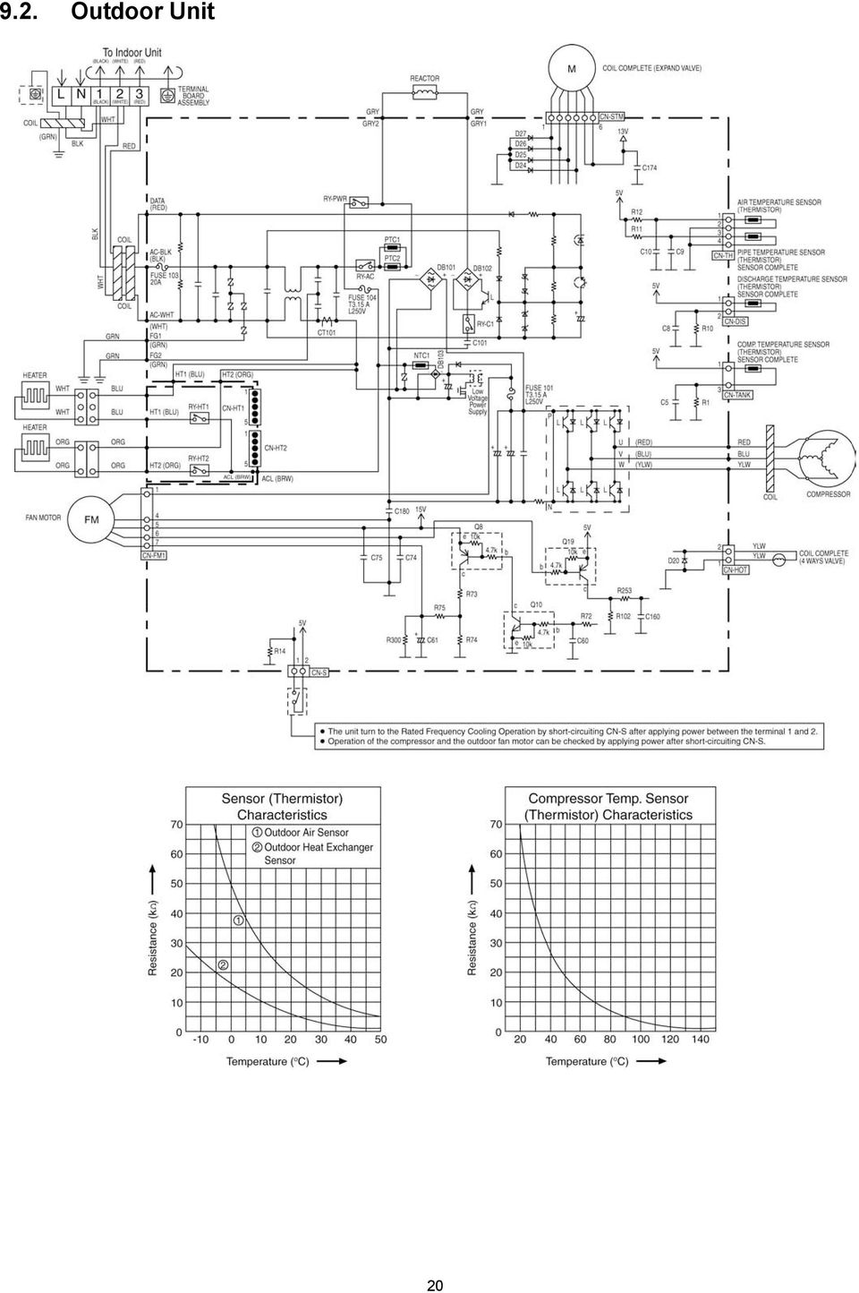
20 9.2. Outdoor Unit 20
21 10 Printed Circuit Board Indoor Unit Main Printed Circuit Board 21
22 Power Printed Circuit Board Indicator Printed Circuit Board 22
23 Receiver Printed Circuit Board High Voltage Power Supply Printed Circuit Board 23
24 10.2. Outdoor Unit 24
25 11 Installation Instruction Select the Best Location Indoor Unit Do not install the unit in excessive oil fume area such as kitchen, workshop and etc. There should not be any heat source or steam near the unit. There should not be any obstacles blocking the air circulation. A place where air circulation in the room is good. A place where drainage can be easily done. A place where noise prevention is taken into consideration. Do not install the unit near the door way. Ensure the spaces indicated by arrows from the wall, ceiling, fence or other obstacles. Recommended installation height for indoor unit shall be at least 2.5 m Outdoor Unit If an awning is built over the unit to prevent direct sunlight or rain, be careful that heat radiation from the condenser is not obstructed. There should not be any animal or plant which could be affected by hot air discharged. Keep the spaces indicated by arrows from wall, ceiling, fence or other obstacles. Do not place any obstacles which may cause a short circuit of the discharged air. If piping length is over the [piping length for additional gas], additional refrigerant should be added as shown in the table Indoor/Outdoor Unit Installation Diagram Model NE9***, XE9*** NE12***, XE12*** Horse Power (HP) Piping size Gas 1.0HP HP mm (3/8 ) Liquid 6.35 mm (1/4 ) Std. Length (m) 5 Max. Elevation (m) Min. Piping Length (m) Max. Piping Length (m) Additional Refrigerant (g/m) Piping Length for add. gas (m) Example: For NE9*** If the unit is installed at 10 m distance, the quantity of additional refrigerant should be 50 g... (10-7.5) m x 20 g/m = 50 g 25
26 11.2. Indoor Unit How to Fix Installation Plate The mounting wall shall be strong and solid enough to prevent it from the vibration To Drill a Hole in the Wall and Install a Sleeve of Piping 1. Insert the piping sleeve to the hole. 2. Fix the bushing to the sleeve. 3. Cut the sleeve until it extrudes about 15 mm from the wall. When the wall is hollow, please be sure to use the sleeve for tube assembly to prevent dangers caused by mice biting the connection cable. 4. Finish by sealing the sleeve with putty or caulking compound at the final stage. Model Dimension NE9***, XE9*** 485 mm 82 mm 165 mm 158 mm 127 mm 85 mm NE12***, XE12*** The center of installation plate should be at more than at right and left of the wall. The distance from installation plate edge to ceiling should more than. From installation plate left edge to unit s left side is. From installation plate right edge to unit s right is. B : For left side piping, piping connection for liquid should be about from this line. : For left side piping, piping connection for gas should be about from this line. 1. Mount the installation plate on the wall with 5 screws or more (at least 5 screws). (If mounting the unit on the concrete wall, consider using anchor bolts.) Always mount the installation plate horizontally by aligning the marking-off line with the thread and using a level gauge Indoor Unit Installation 2. Drill the piping plate hole with ø70 mm hole-core drill. Line according to the left and right side of the installation plate. The meeting point of the extended line is the center of the hole. Another method is by putting measuring tape at position as shown in the diagram above. The hole center is obtained by measuring the distance namely 128 mm for left and right hole respectively. Drill the piping hole at either the right or the left and the hole should be slightly slanting to the outdoor side. 26
27 1. For the right rear piping 2. For the right and right bottom piping 3. For the embedded piping (This can be used for right bottom piping also.) 27
28 Connect the Cable to the Indoor Unit 1. The inside and outside connection cable can be connected without removing the front grille. 2. Connection cable between indoor unit and outdoor unit shall be approved polychloroprene sheathed 4 x 1.5 mm 2 flexible cord, type designation 245 IEC 57 or heavier cord. 3. Bind all the indoor and outdoor connection cable with tape and route the connection cable via the escapement. 4. Remove the tapes and connect the connection cable between indoor unit and outdoor unit according to the diagram below. 5. Secure the connection cable onto the control board with the holder (clamper). Ensure the colour of wires of outdoor unit and the terminal Nos. are the same to the indoor s respectively. Earth wire shall be Yellow/Green (Y/G) in colour and longer than other AC wires for safety reason. 28
29 CUTTING AND FLARING THE PIPING 1. Please cut using pipe cutter and then remove the burrs. 2. Remove the burrs by using reamer. If burrs is not removed, gas leakage may be caused. Turn the piping end down to avoid the metal powder entering the pipe. 3. Please make flare after inserting the flare nut onto the copper pipes. 29
30 11.3. Outdoor Unit Install the Outdoor Unit After selecting the best location, start installation to Indoor/Outdoor Unit Installation Diagram. 1. Fix the unit on concrete or rigid frame firmly and horizontally by bolt nut (ø10 mm). 2. When installing at roof, please consider strong wind and earthquake. Please fasten the installation stand firmly with bolt or nails. Model A B C D NE9*** 570 mm 105 mm 18.5 mm 320 mm NE12*** Connect the Piping Connecting the Piping to Indoor Please make flare after inserting flare nut (locate at joint portion of tube assembly) onto the copper pipe. (In case of using long piping) Connect the piping Align the center of piping and sufficiently tighten the flare nut with fingers. Further tighten the flare nut with torque wrench in specified torque as stated in the table. Do not over tighten, over tightening cause gas leakage. Piping Size Torque 6.35 mm (1/4 ) [18 N m (1.8 kgf.m)] 9.52 mm (3/8 ) [42 N m (4.3 kgf.m)] 12.7 mm (1/2 ) [55 N m (5.6 kgf.m)] mm (5/8 ) [65 N m (6.6 kgf.m)] mm (3/4 ) [100 N m (10.2 kgf.m)] Connecting the Piping to Outdoor Decide piping length and then cut by using pipe cutter. Remove burrs from cut edge. Make flare after inserting the flare nut (located at valve) onto the copper pipe. Align center of piping to valve and then tighten with torque wrench to the specified torque as stated in the table Evacuation of the Equipment WHEN INSTALLING AN AIR CONDITIONER, BE SURE TO EVACUATE THE AIR INSIDE THE INDOOR UNIT AND PIPES in the following procedure. 1. Connect a charging hose with a push pin to the Low side of a charging set and the service port of the 3-way valve. Be sure to connect the end of the charging hose with the push pin to the service port. 2. Connect the center hose of the charging set to a vacuum pump. 3. Turn on the power switch of the vacuum pump and make sure that the needle in the gauge moves from 0 cmhg (0 MPa) to -76 cmhg (-0.1 MPa). Then evacuate the air approximately ten minutes. 4. Close the Low side valve of the charging set and turn off the vacuum pump. Make sure that the needle in the gauge does not move after approximately five minutes. Note: BE SURE TO TAKE THIS PROCEDURE IN ORDER TO AVOID REFRIGERANT GAS LEAKAGE. 30
31 5. Disconnect the charging hose from the vacuum pump and from the service port of the 3-way valve. 6. Tighten the service port caps of the 3-way valve at a torque of 18 N m with a torque wrench. 7. Remove the valve caps of both of the 2-way valve and 3-way valve. Position both of the valves to OPEN using a hexagonal wrench (4 mm). 8. Mount valve caps onto the 2-way valve and the 3-way valve. Be sure to check for gas leakage. If gauge needle does not move from 0 cmhg (0 MPa) to -76 cmhg (-0.1 MPa), in step above take the following measure: - If the leak stops when the piping connections are tightened further, continue working from step. - If the leak does not stop when the connections are retightened, repair the location of leak. - Do not release refrigerant during piping work for installation and reinstallation. - Take care of the liquid refrigerant, it may cause frostbite Connect the Cable to the Outdoor Unit 1. Remove the control board cover from the unit by loosening the screw. 2. Cable connection to the power supply through Isolating Devices (Disconnecting means). Connect approved type polychloroprene sheathed power supply cord 3 x 1.5 mm 2 (1.0 ~ 1.5HP) type designation 245 IEC 57 or heavier cord to the terminal board, and connect the others end of the cord to Isolating Devices (Disconnecting means). 3. Connection cable between indoor unit and outdoor unit shall be approved polychloroprene sheathed 4 x 1.5 mm 2 flexible cord, type designation 245 IEC 57 or heavier cord. 4. Connect the power supply cord and connection cable between indoor unit and outdoor unit according to the diagram below. 5. Secure the power supply cord and connecting cable onto the control board with the holder. 6. Attach the control board cover back to the original position with screw. 7. For wire stripping and connection requirement, refer to instruction of indoor unit. This equipment must be properly earthed. Note: Isolating Devices (Disconnecting means) should have minimum 3.0 mm contact gap. Earth wire shall be Yellow/Green (Y/G) in colour and longer than other AC wires for safety reason Pipe Insulation 1. Please carry out insulation at pipe connection portion as mentioned in Indoor/Outdoor Unit Installation Diagram. Please wrap the insulated piping end to prevent water from going inside the piping. 2. If drain hose or connecting piping is in the room (where dew may form), please increase the insulation by using POLY-E FOAM with thickness 6 mm or above. 31
32 12 Operation and Control Basic Function Inverter control, which equipped with a microcomputer in determining the most suitable operating mode as time passes, automatically adjusts output power for maximum comfort always. In order to achieve the suitable operating mode, the microcomputer maintains the set temperature by measuring the temperature of the environment and performing temperature shifting. The compressor at outdoor unit is operating following the frequency instructed by the microcomputer at indoor unit that judging the condition according to internal setting temperature and intake air temperature Internal Setting Temperature Once the operation starts, remote control setting temperature will be taken as base value for temperature shifting processes. These shifting processes are depending on the air conditioner settings and the operation environment. The final shifted value will be used as internal setting temperature and it is updated continuously whenever the electrical power is supplied to the unit Cooling Operation Thermostat control Compressor is OFF when Intake Air Temperature - Internal Setting Temperature < -1.5 C. Compressor is ON after waiting for 3 minutes, if the Intake Air Temperature - Internal Setting Temperature > Compressor OFF point Soft Dry Operation Thermostat control Compressor is OFF when Intake Air Temperature - Internal Setting Temperature < -2.0 C. Compressor is ON after waiting for 3 minutes, if the Intake Air Temperature - Internal Setting Temperature > Compressor OFF point Heating Operation Thermostat control Compressor is OFF when Intake Air Temperature - Internal Setting Temperature > +2.0 C. Compressor is ON after waiting for 3 minutes, if the Intake Air Temperature - Internal Setting Temperature < Compressor OFF point. 32
33 Automatic Operation This mode can be set using remote control and the operation is decided by remote control setting temperature, remote control operation mode, indoor intake air temperature and outdoor air temperature. During operation mode judgment, indoor fan motor (with speed of Lo-) and outdoor fan motor are running for 30 seconds to detect the indoor intake and outdoor air temperature. The operation mode is decided based on below chart. Every 30 minutes, the indoor and outdoor temperature is judged. Based on remote control setting temperature, the value of T1 will increase up to 10 C, T2 will decrease by 3 C and T3 will decrease up to 8 C. The Auto Operation Mode shifting will take place whenever operation mode changed from Cool/Soft Dry to Heating or vice versa Fan Operation Fan Operation is used to circulate air in a room. During operation, indoor fan run continuously but outdoor fan and compressor stop. Temperature setting is not applicable Indoor Fan Motor Operation A. Basic Rotation Speed (rpm) i. Manual Fan Speed [Cooling, Dry, Fan] Fan motor s number of rotation is determined according to remote control setting. Remote Control O O O O O Tab Hi Me+ Me Me- Lo [Heating] Fan motor s number of rotation is determined according to remote control setting. Remote Control O O O O O Tab SHi Me+ Me Me- Lo ii. Auto Fan Speed [Cooling, Dry] According to room temperature and setting temperature, indoor fan speed is determined automatically. The indoor fan will operate according to pattern below. [Fan] Indoor fan speed is fixed at predetermined speed. 33
34 [Heating] According to indoor pipe temperature, automatic heating fan speed is determined as follows. B. Feedback control Immediately after the fan motor started, feedback control is performed once every second. During fan motor on, if fan motor feedback 2550 rpm or < 50 rpm continue for 10 seconds, then fan motor error counter increase, fan motor is then stop and restart. If the fan motor counter becomes 7 times, then H19 - fan motor error is detected. Operation stops and cannot on back Outdoor Fan Motor Operation Outdoor fan motor is operated with 15 fan speed number of rotations. It starts when compressor starts operation and it stops 30 seconds after compressor stops operation Airflow Direction 1. There are two types of airflow, vertical airflow (directed by horizontal vane) and horizontal airflow (directed by vertical vanes). 2. Control of airflow direction can be automatic (angles of direction is determined by operation mode, heat exchanger temperature and intake air temperature) and manual (angles of direction can be adjusted using remote control) Vertical Airflow Operation Mode Airflow Direction Vane Angle ( ) Heating Auto with Heat Exchanger A 20 Temperature B 58 C 33 Manual Cooling, e-ion and Fan Auto 20 ~ 46 Manual Soft Dry Auto 20 ~ 46 Manual Automatic vertical airflow direction can be set using remote control; the vane swings up and down within the angles as stated above. For heating mode operation, the angle of the vane depands on the indoor heat exchanger temperature as Figure 1 below. When the air conditioner is stopped using remote control, the vane will shift to close position. 2. Manual vertical airflow direction can be set using remote control; the angles of the vane are as stated above and the positions of the vane are as Figure 2 below. When the air conditioner is stopped using remote control, the vane will shift to close position. 34
35 Horizontal Airflow The horizontal airflow direction louvers can be adjusted manually by hand Quiet operation (Cooling Mode/Cooling area of Dry Mode) A. Purpose To provide quiet cooling operation compare to normal operation. B. Control condition a. Quiet operation start condition When Quiet button at remote control is pressed. Quiet LED illuminates. b. Quiet operation stop condition 1. When one of the following conditions is satisfied, quiet operation stops: a. Powerful button is pressed. b. Stop by OFF/ON switch. c. Timer off activates. d. Quiet button is pressed again. 2. When quiet operation is stopped, operation is shifted to normal operation with previous setting. 3. When fan speed is changed, quiet operation is shifted to quiet operation of the new fan speed. 4. When operation mode is changed, quiet operation is shifted to quiet operation of the new mode. 5. During quiet operation, if timer on activates, quiet operation maintains. 6. After off, when on back, quiet operation is not memorised. C. Control contents 1. Fan speed is changed from normal setting to quiet setting of respective fan speed. This is to reduce sound of Hi, Me, Lo for 3dB (some models more than 3dB). 2. Fan speed for quiet operation is reduced from setting fan speed Quiet operation (Heating) A. Purpose To provide quiet heating operation compare to normal operation. B. Control condition a. Quiet operation start condition When Quiet button at remote control is pressed. Quiet LED illuminates. b. Quiet operation stop condition 1. When one of the following conditions is satisfied, quiet operation stops: a. Powerful button is pressed. b. Stop by OFF/ON switch. c. Timer off activates. d. Quiet button is pressed again. 2. When quiet operation is stopped, operation is shifted to normal operation with previous setting. 3. When fan speed is changed, quiet operation is shifted to quiet operation of the new fan speed. 4. When operation mode is changed, quiet operation is shifted to quiet operation of the new mode, expect fan only mode. 5. During quiet operation, if timer on activates, quiet operation maintains. 6. After off, when on back, quiet operation is not memorised. 35
36 C. Control contents a. Fan Speed manual 1. Fan speed is changed from normal setting to quiet setting of respective fan speed. This is to reduce sound of Hi, Me, Lo for 3dB. 2. Fan speed for quiet operation is reduced from setting fan speed. b. Fan Speed Auto 1. Indoor FM RPM depends on pipe temp sensor of indoor heat exchanger Powerful Mode Operation When the powerful mode is selected, the internal setting temperature will shift lower up to 2 C (for Cooling/Soft Dry) or higher up to 3.5 C (for Heating) than remote control setting temperature for 20 minutes to achieve the setting temperature quickly Timer Control ON Timer Control ON timer can be set using remote control, the unit with timer set will start operate earlier than the setting time. This is to provide a comfortable environment when reaching the set ON time. 60 minutes before the set time, indoor (at fan speed of Lo-) and outdoor fan motor start operate for 30 seconds to determine the indoor intake air temperature and outdoor air temperature in order to judge the operation starting time. From the above judgment, the decided operation will start operate earlier than the set time as shown below OFF Timer Control OFF timer can be set using remote control, the unit with timer set will stop operate at set time Auto Restart Control 1. When the power supply is cut off during the operation of air conditioner, the compressor will re-operate within three to four minutes (there are 10 patterns between 2 minutes 58 seconds and 3 minutes 52 seconds to be selected randomly) after power supply resumes. 2. This type of control is not applicable during ON/OFF Timer setting Indication Panel PATROL LED POWER/DIECE TIMER QUIET POWERFUL e-ion +8/10 C HEAT SENSOR Color Green Blue Orange Orange Orange Blue Green Blue Light ON Operation ON Deice Operation Timer Setting ON Quiet Mode ON Light OFF Operation OFF Timer Setting OFF Quiet Mode OFF Powerful Mode ON Powerful Mode OFF e-ion ON e-ion OFF +8/10 C HEAT ON +8/10 C HEAT OFF PATROL ON Note: If POWER LED is blinking, the possible operation of the unit are Hot Start, operation mode judgment, or ON timer sampling. If Timer LED is blinking, there is an abnormality operation occurs. If e-ion LED is blinking, there is an abnormality of e-ion occurs. If PATROL LED is blinking, there is a gas sensor error detection. PATROL OFF 36
37 Patrol Operation A. Purpose To monitor air dirtiness level by using Patrol sensor and to maintain air freshness by activates e-ion operation. B. Control Condition a. Patrol operation start condition When the unit operation is started with OFF/ON button. When the unit stops, Patrol button is pressed, Patrol individual operation will start. During cooling only operation, Patrol button is pressed. b. Patrol operation stop condition When any of the following condition is fulfilled: When OFF/ON button is pressed. During any operation with Patrol, Patrol button is pressed again. When e-ion button is pressed. When OFF Timer activates. c. Patrol operation disable To disable the Patrol Operation during unit start (default) with OFF/ON button, press Patrol button and hold for 5 seconds, then release. To disable the Patrol Operation, press Patrol button and hold for 15 seconds, then release. C. Control Content a. Patrol Sensor Control First 2 minutes from Patrol function activates is stabilization time, during stabilization time, no air dirtiness level is monitored. The Air Dirtiness level is set to level 2. After that, gas sensor starts to record the resistance value at fixed interval. Higher resistance value indicates cleaner air. The air dirtiness level is monitored by comparing the current resistance value with maximum resistance value from time to time to get the Air Dirtiness Value. There are 3 air dirtiness levels, based on the Air Dirtiness Value: - Air Dirtiness level 0: Clean - Air Dirtiness level 1: Moderate - Air Dirtiness level 2: Contaminated 37
38 Dirtiness level sensitivity adjustment It is possible to change the gas sensor sensitivity, where the Threshold value (G1 ~ G4) will be shifted accordingly: 1. Press and release SET buttton. 2. Press Timer increment / Timer decrement button to select sensitivity. (Low Standard (Default) High) 3. Confirm setting by pressing Timer Set button. LCD returned to original display after 2 seconds. 4. LCD returned to original display if remote control does not operate for 30 seconds. b. e-ion Control When dirtiness level is 1 or 2, e-ion operation starts. If dirtiness level improves from level 2 to level 1, the unit carries out level change after 60 seconds. When dirtiness level returns to level 0 continuously for 10 minutes or more, e-ion operation stops. Dirtiness Level Shift For Auto Fan Speed, the fan speed increased based on dirtiness level: c. Indoor Fan Control During any operation mode combines with Patrol operation, fan speed follows respective operation mode. During Patrol individual operation if e-ion starts, only Auto Fan Speed and no Powerful operation is allowed. Even if Fan Speed button is pressed, no signal is sent to air conditioner, and no change on LCD display. During Patrol individual operation if e-ion stops, Indoor Fan stop operation. d. Airflow direction (Horizontal, Vertical) Control During any operation mode combines with Patrol operation, airflow direction follows respective operation mode. During Patrol individual operation if e-ion starts, only Auto Air Swing is allowed. Even if Air Swing button is pressed, no signal is sent to air conditioner, and no change on LCD display. During Patrol individual operation if e-ion stops, Airflow direction louver closed. e. Indicator When Patrol operation starts, Patrol Sensor indicator ON. When e-ion operation starts based on dirtiness level, e-ion indicator ON. f. Remote Control Receiving Sound Normal Operation Patrol Mode Patrol Mode Stop Patrol Mode Stop Normal Operation Patrol : : : : Beep Long Beep Beep Beep g. Timer Control When ON timer activates when unit stops, previous operation resumes and restored last saved patrol operation status. When ON timer activates during any operation, no change and carry on current operation. When OFF timer activates during any operation, all operation stops and the latest patrol operation status is saved. 38
39 h. Power failure During Patrol individual operation, if power failure occurs, after power resumes, Patrol individual operation resumes immediately. During combination operation, if power failure occurs, after power resumes combination operation resume immediately. i. Error Detection Control The Patrol error detection control starts once the power is supplied to Patrol sensor. However, the error will display when the Patrol operation is ON. Error detection method: - If the Patrol sensor feedback is 0V or 5V continuous for 6 hours, Patrol sensor error occurs. However, the error will display only when the Patrol operation is ON. Patrol Sensor Control after error occurs - During any operation mode combines with Patrol operation Power supply to Patrol sensor is OFF Air conditioner normal mode operation continues with Patrol LED and Timer LED blinking and H58 is indicated. Timer LED will always blinking and the Patrol LED continues blinking if the Patrol operation is ON and stops blinking if the patrol operation is OFF. - During Patrol individual mode Power supply to Patrol sensor is OFF Patrol LED and Timer LED blinking and H58 is indicated. Timer LED will always blinking and the Patrol LED continues blinking if the Patrol operation is ON and stops blinking if the Patrol operation is OFF. Error cancel condition: - Power supply reset e-ion Operation A. Purpose This operation provides clean air by producing negative ions to attract dust captured at the positively charged e-ion filters. B. Control Condition a. e-ion operation start condition During unit running at any operation mode, if e-ion button is pressed, combination operation (operation mode + e-ion operation) starts. During unit is OFF, if e-ion button is pressed, e-ion individual operation starts. b. e-ion operation stop condition When OFF/ON button is pressed to stop the operation. When e-ion button is pressed again. When Patrol button is pressed. When OFF Timer activates. c. e-ion operation pause condition When indoor fan stop (during deice, odor cut control, thermostat off, etc.). e-ion operation resume after indoor fan restarts. When indoor intake temperature 40 C. e-ion operation resume after indoor intake temperature < 40 C continuously for 30 minutes. 39
CS-HE9NKE CS-HE12NKE CS-AE9NKE CU-HE9NKE CU-HE12NKE CU-AE9NKE TABLE OF CONTENTS WARNING
 Order No: PAPAMY1207093CE Indoor Unit CS-HE9NKE CS-HE12NKE CS-AE9NKE Outdoor Unit CU-HE9NKE CU-HE12NKE CU-AE9NKE WARNING This service information is designed for experienced repair technicians only and
CS-CE9NKE CS-CE12NKE CU-CE9NKE CU-CE12NKE TABLE OF CONTENTS WARNING
 Order No: PAPAMY1207094CE Indoor Unit CS-CE9NKE CS-CE12NKE Outdoor Unit CU-CE9NKE CU-CE12NKE WARNING This service information is designed for experienced repair technicians only and is not designed for
CU-S9KKQ CU-S12KKQ CU-S18KKQ CU-S24KKQ CS-S9KKQ CS-S12KKQ CS-S18KKQ CS-S24KKQ WARNING
 Order No: PHAAM1001037C3 Indoor Unit CS-S9KKQ CS-S12KKQ CS-S18KKQ CS-S24KKQ Outdoor Unit CU-S9KKQ CU-S12KKQ CU-S18KKQ CU-S24KKQ WARNING This service information is designed for experienced repair technicians
CU-2E15LBE CU-2E18LBE CU-3E18LBE CU-4E23LBE
 Order No. PHAAM1003090C3 Outdoor Unit CU-2E15LBE CU-2E18LBE CU-3E18LBE CU-4E23LBE Air Conditioner Please file and use this manual together with the service manual for Model No. CS-E7LKEW CU-E7LKE CS-E7LKEW
CS-XE9EKE CU-XE9EKE CS-XE12EKE CU-XE12EKE
 Order No. MAC0512111C8 Air Conditioner CS-XE9EKE CU-XE9EKE CS-XE12EKE CU-XE12EKE TABLE OF CONTENTS PAGE 1 Safety Precautions----------------------------------------------- 3 2 Specifications -----------------------------------------------------
Air Conditioner CU-XE9PKUA CU-XE12PKUA CS-XE9PKUA CS-XE12PKUA. Destination U.S.A. Canada WARNING
 Order No: PAPAMY1305056CE Air Conditioner Indoor Unit CS-XE9PKUA CS-XE12PKUA Outdoor Unit CU-XE9PKUA CU-XE12PKUA Destination U.S.A. Canada WARNING This service information is designed for experienced repair
Split-type Air-Conditioner INSTALLATION MANUAL CONTENTS FOR INSTALLER MXZ-3A30NA MXZ-4A36NA ATTENTION. English. Français. Español
 Split-type Air-Conditioner MXZ-3A30NA MXZ-4A36NA INSTALLATION MANUAL Refer to the installation manual of each indoor unit for indoor unit installation. English Français Español ATTENTION This manual mentions
TECHNICAL DATA & SERVICE MANUAL SPLIT SYSTEM AIR CONDITIONER INDOOR UNIT: AW52AL AW64AL AW52AL 387030095 AW64AL 0.8180.463.0 07/05
 TECHNICAL DATA & SERVICE MANUAL INDOOR UNIT: AW52AL AW64AL SPLIT SYSTEM AIR CONDITIONER Model No. Product Code No. AW52AL 387030095 AW64AL 387030096 0.8180.463.0 07/05 IMPORTANT! Please read before installation
WH-UD09CE8 WH-UD12CE8 WH-UD14CE8 WH-UD16CE8 WH-SDF09C3E8 WH-SDF12C9E8 WH-SDF14C9E8 WH-SDF16C9E8 WARNING
 Order No. PHAAM1009094C2 Indoor Unit WH-SDF09C3E8 WH-SDF12C9E8 WH-SDF14C9E8 WH-SDF16C9E8 Outdoor Unit WH-UD09CE8 WH-UD12CE8 WH-UD14CE8 WH-UD16CE8 WARNING This service information is designed for experienced
TABLE OF CONTENTS. Air Conditioner CS-E9HKEA CU-E9HKEA CS-E12HKEA CU-E12HKEA
 Order No. MAC0801090C2 Air Conditioner CS-E9HKEA CU-E9HKEA CS-E12HKEA CU-E12HKEA TABLE OF CONTENTS PAGE 1 Safety Precaution ------------------------------------------------ 2 2 Specifications -----------------------------------------------------
Operating Instructions Split System Air Conditioner
 Operating Instructions Split System Air Conditioner Model No. Indoor Unit Type Indoor Unit Type Nominal Capacity 26 36 F2 Low Silhouette Ducted S-26PF2U6 S-36PF2U6 Connectable outdoor unit lineup This
FAN SPEED AIR SWING SET CANCEL FAN AIR SWING SET CANCEL WARNING
 AUT O HE AT COOL DRY AUT O HE AT COOL DRY FAN SP E ED FAN SPEED AC AC AIR SWING SE T CHE CK CLOCK RE SE T AIR SWING SE T CHE CK CLOCK RE SE T FAN SPEED AIR SWING RC RC Order No: PAPAMY32039CE (YE9/2QKE)
Air Conditioner CONTENTS CS-TE9DKE CU-TE9DKE CS-TE12DKE CU-TE12DKE. Order No. RAC0502005C2
 Order No. RAC0502005C2 Air Conditioner CS-TE9DKE CU-TE9DKE CS-TE12DKE CU-TE12DKE CONTENTS Page Page 1 Features 2 2 Functions 3 2.1. Remote Control 3 2.2. Indoor Unit 4 2.3. Outdoor unit 5 3 Product Specifications
AIR-CONDITIONER SPLIT TYPE
 FILE NO. A08-016 SERVICE MANUAL AIR-CONDITIONER SPLIT TYPE RAS-M10PKVP-E, RAS-M13PKVP-E, RAS-M16PKVP-E, RAS-M18PKVP-E / RAS-M10PKVP-ND, RAS-M13PKVP-ND, RAS-M16PKVP-ND, RAS-M18PKVP-ND / RAS-3M26GAV-E1,
Operating Instructions Air Conditioner
 F566272 Operating Instructions Air Conditioner CS-C18FFH CS-C28FFH CU-C18FFH CU-C28FFH ENGLISH Before operating the unit, read these operating instructions thoroughly and keep them for future reference.
Air Conditioner CONTENTS CS-V7DKE CU-V7DKE CS-V9DKE CU-V9DKE CS-V12DKE CU-V12DKE. Order No. MAC0412062C2
 Order No. MAC0412062C2 CS-V7DKE CU-V7DKE CS-V9DKE CU-V9DKE CS-V12DKE CU-V12DKE Air Conditioner CONTENTS Page Page 1 Features 3 2 Functions 4 2.1. Remote Control 4 2.2. Indoor Unit 5 2.3. Outdoor Unit 6
SERVICE MANUAL SPLIT SYSTEM ROOM AIR CONDITIONER SHARP CORPORATION SHARP CORPORATION CONTENTS
 SERVICE MANUAL SPLIT SYSTEM ROOM AIR CONDITIONER INDOOR UNIT AH-129 AH-MP14 OUTDOOR UNIT AU-129 AU-MP14 CONTENTS SPECIFICATIONS...2 EXTERNAL DIMENSIONS...4 WIRING DIAGRAMS...5 ELECTRICAL PARTS...6 MICROCOMPUTER
SERVICE MANUAL. Room Air Conditioner Multi Split Wall-Mounted Type Indoor. FSAI-Pro-91AE2 FSAI-Pro-121AE2 FSAIF-Pro-181AE2
 SERVICE MANUAL Room Air Conditioner Multi Split Wall-Mounted Type Indoor FSAI-Pro-91AE2 FSAI-Pro-121AE2 FSAIF-Pro-181AE2 NOTE: Before servicing the unit, please read this at first. Always contact with
ROOM AIR CONDITIONER INSTALLATION MANUAL
 ROOM AIR CONDITIONER INSTALLATION MANUAL ( Split Type) Please read this installation manual completely before installing the product When the power cord is damaged, replacement work shall be performed
CU-NE9PKE CU-NE12PKE CU-QE9PKE CU-QE12PKE CS-NE9PKE CS-NE12PKE CS-QE9PKE CS-QE12PKE. Destination North Europe TABLE OF CONTENTS WARNING
 Order No: PAPAMY3072CE Indoor Unit CS-NE9PKE CS-NE2PKE CS-QE9PKE CS-QE2PKE Outdoor Unit CU-NE9PKE CU-NE2PKE CU-QE9PKE CU-QE2PKE Destination North Europe WARNING This service information is designed for
Monobloc Air-to-Water Heatpump System
 Order No. PHAAM1010087C2 Monobloc Air-to-Water Heatpump System Monobloc Unit WH-MDF09C3E8 WH-MDF12C9E8 WH-MDF14C9E8 WH-MDF16C9E8 WARNING This service information is designed for experienced repair technicians
Dehumidifier Users manual. For Models: DH45S DH65S
 Dehumidifier Users manual For Models: DH45S DH65S 950-0062-revD Jan. 9 2007 FORWARD The appearance of the units that you purchase might be slightly different from the ones described in the Manual, but
SWIMMING POOL HEAT PUMP
 SWIMMING POOL HEAT PUMP Installation & User Manual Model HP40B HP50B HP65B Hayward Pool Products Canada, Inc. T: 1-888-238-7665 www.haywardpool.ca CONTENT I. Application 4 II. Features 4 III. Technical
14. Troubleshooting Guide
 14. Guide 14.1 Refrigeration Cycle System In order to diagnose malfunctions, ensure the air conditioner is free from electrical problems before inspecting the refrigeration cycle. Such problems include
USER INSTRUCTIONS FOR GET PORTABLE 12k BTU AIR CONDITIONER MODEL No. GPACU12HR
 USER INSTRUCTIONS FOR GET PORTABLE 12k BTU AIR CONDITIONER MODEL No. GPACU12HR CONTENTS Introduction Safety Notes Identification of parts Installation instructions Operation instructions Maintenance Troubleshooting
Portable Air Conditioner
 Portable Air Conditioner Owner's Manual Model:3 in 1 12,000 Btu/h Series 3 Please read this owner s manual carefully before operation and retain it for future reference. CONTENTS 1. SUMMARY...1 2. PORTABLE
SPLIT -TYPE ROOM AIR CONDITIONER
 Before using your air conditioner, please read this manual carefully and keep it for future reference SPLIT -TYPE ROOM AIR CONDITIONER Please read this installation manual completely before installing
york air-conditioning products Residential & VRF News 2015
 york air-conditioning products Residential & VRF News 2015 york air-conditioning products Catalogue Content Split Systems Pag. High wall High Efficiency Inverter YWHJZH 09 to 24 K 6 High wall Inverter
Use and Care Manual. Model CPA12KH AIR CONDITIONER
 Use and Care Manual Model CPA12KH AIR CONDITIONER Introduction Thank you for choosing this air conditioner to provide you and your family with all of the "Home Comfort" requirements for your home, cottage
Floor Type Air-Conditioner INSTALLATION MANUAL CONTENTS FOR INSTALLER MFZ-KA25VA MFZ-KA35VA MFZ-KA50VA. English
 Floor Type Air-Conditioner MFZ-KA25VA MFZ-KA35VA MFZ-KA50VA INSTALLATION MANUAL This manual only describes the installation of indoor unit. When installing the outdoor unit, refer to the installation manual
USER S MANUAL HSC-24A
 AIRREX AIR CONDITIONER USER S MANUAL HSC-24A Thank you for purchasing an AIRREX AIR CONDITIONER. BEFORE operation please read this user s manual carefully. Keep this manual readily available. It is ESSENTIAL
New Deluxe Wall Mounted Heat Pump Series EXTERIOS
 New Deluxe Wall Mounted Heat Pump Series EXTERIOS May 2013 New Deluxe Wall Mounted Heat Pump Series Panasonic Adding New Air Conditioner Lineup Setting Another Mile Stone in the US Ductless Split History
Wall Mounted Mini Split Heat Pump Air Conditioner
 Wall Mounted Mini Split Heat Pump Air Conditioner OPERATING AND INSTALLATION MANUAL Model: KFIHP-09-ID / KFHIP-09-OD KFHHP-12-ID / KFHHP-12-OD Indoor Unit. Outdoor Unit. Thank you for selecting Soleus
CONTENTS 1. IMPORTANT NOTICE 2 2. TECHNICAL SPECIFICATION 3 3. OPERATION DETAILS 4 4. ELECTRICAL SCHEMATIC DIAGRAM 13 5. EXPLOSION VIEW 16 6
 TCL WALL MOUNTED SPLIT-TYPE AIR CONDITIONERS SERVICE MANUAL No.TE080528 Models KFTHP-12 KFTHP-18 KFTHP-24 CONTENTS 1. IMPORTANT NOTICE 2 2. TECHNICAL SPECIFICATION 3 3. OPERATION DETAILS 4 4. ELECTRICAL
HP switch LP switch Discharge thermo Comp. Surface thermo
 1 Specifications Zubadan Model Name PUHZ-SHW80VHA PUHZ-SHW11VHA PUHZ-SHW11YHA Power supply (phase, cycle, voltage) 1φ, V, Hz 1φ, V, Hz 3φ, 0V, Hz Max. current A 9.5 35.0 13.0 Breaker size A 3 16 Outer
Split Type Room Air Conditioner. KSWM units
 OWNER S MANUAL Split Type Room Air Conditioner KSWM units Please read the operating instructions and safety precautions carefully and thoroughly before installing and operating your room air conditioner.
NewAir AC-10000E, AC-10000H Portable Air Conditioner Owner s Manual PLEASE READ AND SAVE THESE INSTRUCTIONS
 NewAir AC-10000E, AC-10000H Portable Air Conditioner Owner s Manual PLEASE READ AND SAVE THESE INSTRUCTIONS BEFORE USE GENERAL SAFETY INSTRUCTIONS: ALWAYS OPERATE THE UNIT IN AN UPRIGHT POSITION AND PLACE
Operating Instructions Air Conditioner
 P07-T10130 Operating Instructions Air Conditioner Indoor Unit CS-F24DD1E5 CS-F28DD1E5 CS-F34DD1E5 CS-F43DD1E5 CS-F50DD1E5 Outdoor Unit Inverter Model (HBE5 Series) CU-YL24HBE5 CU-YL28HBE5 CU-YL34HBE5 CU-YL43HBE5
CONTENTS 1. IMPORTANT NOTICE 2 2. TECHNICAL SPECIFICATION 3 3. OPERATION DETAILS 4 4. WIRING DIAGRAM 11 5. EXPLOSION VIEW 12 6.
 TCL WALL MOUNTED SPLIT-TYPE AIR CONDITIONERS SERVICE MANUAL No.TE051220 Models TAC-09CHSA/GI TAC-12CHSA/GI CONTENTS 1. IMPORTANT NOTICE 2 2. TECHNICAL SPECIFICATION 3 3. OPERATION DETAILS 4 4. WIRING DIAGRAM
technical data air conditioning systems RXS20-25-35E (single phase) FBQ-B8V1-B8V3B Split Heat Pump Condensing Units Split Sky Air
 FBQ-B8V1-B8V3B Split Heat Pump Condensing Units Split Sky Air") technical data RXS20-25-35E FBQ-B8V-B8V3B (single phase) Split Heat Pump Condensing Units air conditioning systems Split Sky Air Outdoor Units R-40A RXS-E2VB Split Sky Air Outdoor Units Features O u t
technical data RXS20-25-35E FBQ-B8V-B8V3B (single phase) Split Heat Pump Condensing Units air conditioning systems Split Sky Air Outdoor Units R-40A RXS-E2VB Split Sky Air Outdoor Units Features O u t
NewAir AC-10100E / AC-10100H Portable Air Conditioner Owner s Manual PLEASE READ AND SAVE THESE INSTRUCTIONS
 NewAir AC-10100E / AC-10100H Portable Air Conditioner Owner s Manual PLEASE READ AND SAVE THESE INSTRUCTIONS ELECTRICAL SAFETY This appliance is for indoor use only. Always turn off the unit and unplug
Air Conditioner Water Heater - A Product of HotSpot Energy LLC
 Air Conditioner Water Heater - A Product of HotSpot Energy LLC PLEASE READ THIS BEFORE YOU INSTALL THE UNIT 1. This air conditioner must be installed and/or repaired by a qualified technician. If you perform
Air Conditioners Technical Data
 Air Conditioners Technical Data O u t d o o r U n i t E E D E N 2-0 0 RX-JV Outdoor Unit RX-JV TABLE OF CONTENTS RX-JV Features............................................................. 2 2 Specifications.......................................................
SPLIT WALL MOUNTED TYPE AIR CONDITIONERS OWNER'S MANUAL
 SPLIT WALL MOUNTED TYPE AIR CONDITIONERS OWNER'S MANUAL Thank you for choosing our Air Conditioner. Please read this OWNER'S MANUAL carefully prior to use and keep it for further reference. CONTENTS Contents
AIR CONDITIONER INSTALLATION MANUAL
 INSTALLATION MANUAL AIR CONDITIONER Please read this installation manual completely before installing the product. Installation work must be performed in accordance with the national wiring standards by
Portable Air Conditioner. OWNER S MANUAL Read these instructions before use. Model: MF08CESWW. Voltage rating: 115V~60Hz Power rating : 800W
 MODE ALARM Portable Air Conditioner OWNER S MANUAL Read these instructions before use 8 Model: MF08CESWW Voltage rating: 115V~60Hz Power rating : 800W Customer Support : 1-800-474-2147 For product inquiries
OPTIONAL SLENDER REMOTE CONTROL
 DAIKIN ROOM AIR CONDITIONER Operation Manual OPTIONAL SLENDER REMOTE CONTROL BRC944A2B READ BEFORE OPERATION Safety Precautions...2 Names of Functions of Parts...4 Preparation before Operation...5 OPERATION
CS-PE9CKE CU-PE9CKE CS-PE12CKE CU-PE12CKE
 Order No. GMAC0401003C2 CS-PE9CKE CU-PE9CKE CS-PE12CKE CU-PE12CKE Room Air Conditioners CONTENTS Page 1 Functions 2 2 Product Specifications 5 3 Dimensions 9 4 Refrigeration Cycle Diagram 11 5 Block Diagram
LG Floor Standing Type Air Conditioner INSTALLATION MANUAL
 website http://www.lgservice.com e-mail http://www.lgeservice.com/techsup.html LG Floor Standing Type Air Conditioner INSTALLATION MANUAL LG IMPORTANT Please read this installation manual completely before
WINDOW ROOM AIR CONDITIONER
 WINDOW ROOM AIR CONDITIONER Installation and Operation Manual Electromechanical Remote Control CAPACITIES 220V - 60 HZ. 12,000; 18,000; 24000 BTU/HR 220V-240V - 50 HZ. 12,000; 18,000; 24000 BTU/HR Please
Portable Air Conditioner. OWNER S MANUAL Read these instructions before use. Model: MM14CCS. Voltage rating: 115V~60Hz Power rating : 1400W
 Portable Air Conditioner OWNER S MANUAL Read these instructions before use Model: MM14CCS Customer Support : 1-800-474-2147 Voltage rating: 115V~60Hz Power rating : 1400W For product inquiries or support
Portable Air Conditioner. OWNER S MANUAL Read these instructions before use. Model: MN12CES / MN10CESWW
 Portable Air Conditioner OWNER S MANUAL Read these instructions before use 8 Model: MN12CES / MN10CESWW Voltage rating: 120V~60Hz Power rating : 1100W (MN12CES) Power rating : 900W (MN10CESWW) Customer
PORTABLE AIR CONDITIONER
 PORTABLE AIR CONDITIONER MAC 7500 Owner s Manual Air Conditioner Dehumidifier Oscillating Fan Please read this owner s manual carefully before operating the unit. POWERED BY 66126113.p65 17 INTRODUCTION
AIR CONDITIONER (SPLIT TYPE)
") OWNER S MANUAL AIR CONDITIONER (SPLIT TYPE) For general public use ENGLISH EN Indoor Unit RAS-07PKVP-E RAS-10PKVP-E RAS-13PKVP-E RAS-16PKVP-E RAS-18PKVP-E RAS-07PKVP-ND RAS-10PKVP-ND RAS-13PKVP-ND RAS-16PKVP-ND
OWNER S MANUAL AIR CONDITIONER (SPLIT TYPE) For general public use ENGLISH EN Indoor Unit RAS-07PKVP-E RAS-10PKVP-E RAS-13PKVP-E RAS-16PKVP-E RAS-18PKVP-E RAS-07PKVP-ND RAS-10PKVP-ND RAS-13PKVP-ND RAS-16PKVP-ND
Please read this owner s Manual carefully before operating the unit. - Cooling - Heating - Dehumidifying - Fan
 Please read this owner s Manual carefully before operating the unit. - Cooling - Heating - Dehumidifying - Fan TABLE OF CONTENTS INTRODUCTION 2 IMPORTANT SAFEGUARDS...2 PACKAGE CONTAINS..2 NAMES OF PARTS.3
CEILING CASSETTE TYPE AIR CONDITIONERS INSTALLATION INSTRUCTIONS
 CEILING CASSETTE TYPE AIR CONDITIONERS INSTALLATION INSTRUCTIONS Please read this instruction sheet completely before installing the product. When the power cord is damaged, replacement work should be
Si10-417_C. Pocket Manual. Service Diagnosis SPLIT & MULTI
 Pocket Manual Service Diagnosis SPLIT & MULTI Service Diagnosis SPLIT & MULTI 1. Troubleshooting with LED...5 1.1 Indoor Unit... 5 1.2 Outdoor Unit... 10 2. Troubleshooting by Symptoms...11 2.1 Air conditioner
AIR CONDITIONER INSTALLATION MANUAL
 FRANCAIS ESPAÑOL INSTALLATION MANUAL AIR CONDITIONER Please read this installation manual completely before installing the product. Installation work must be performed in accordance with the national wiring
USER S MANUAL FH052EAV1 FH070EAV1. System Air Conditioner (Cooling and Heating) ENGLISH ESPAÑOL FRANÇAIS ITALIANO PORTUGUÊS DEUTSCH E HNIKA
 ENGLISH ESPAÑOL FRANÇAIS ITALIANO PORTUGUÊS DEUTSCH E HNIKA") USER S MANUAL FH052EAV1 FH070EAV1 E HNIKA PORTUGUÊS ENGLISH ESPAÑOL ITALIANO DEUTSCH FRANÇAIS System Air Conditioner (Cooling and Heating) E S F I P D G DB98-29263A(1) Safety Precautions Register your
USER S MANUAL FH052EAV1 FH070EAV1 E HNIKA PORTUGUÊS ENGLISH ESPAÑOL ITALIANO DEUTSCH FRANÇAIS System Air Conditioner (Cooling and Heating) E S F I P D G DB98-29263A(1) Safety Precautions Register your
Service manual. Website: www.andico.com.au CAUTION - BEFORE SERVICING THE UNIT, READ THE SAFETY - PRECAUTIONS IN THIS MANUAL.
 Website: www.andico.com.au Service manual CAUTION - BEFORE SERVICING THE UNIT, READ THE SAFETY - PRECAUTIONS IN THIS MANUAL. - ONLY FOR AUTHORISED SERVICE PERSONNEL. MODELS: MPK1-09CR-QB8 MPK1-12ER-QB6
UB1 AIR CONDITIONING UNIT INSTALLATION INSTRUCTIONS
 UB1 AIR CONDITIONING UNIT INSTALLATION INSTRUCTIONS INSTALLATION INSTRUCTIONS: Carefully read these instructions before installing your new air-conditioner. AUSTRALIAN AUTOMOTIVE AIR AL00500054E 1 Table
SERVICE MANUAL OUTDOOR UNIT. No. OBH590 REVISED EDITION-B. Models HFC
 SPLIT-TYPE AIR CONDITIONERS Revision B: MUZ-EF25/35/42/50VE - E2 and MUZ-EF25/35VEH - E2 have been added. Please void OBH590 REVISED EDITION-A. OUTDOOR UNIT SERVICE MANUAL HFC utilized R410A. OBH590 REVISED
SERVICE INSTRUCTION R410A. WALL MOUNTEDtype INVERTER SPLIT TYPE ROOM AIR CONDITIONER. Models Indoor unit Outdoor unit
 SERVICE INSTRUCTION SPLIT TYPE ROOM AIR CONDITIONER WALL MOUNTEDtype INVERTER Models Indoor unit Outdoor unit ASYG07LECA ASYG09LECA ASYG12LECA ASYG14LECA AOYG07LEC AOYG09LEC AOYG12LEC AOYG14LEC R410A CONTENTS
Appendix - Controllers 179
 Version: 200703 Appendix - Controllers 179 -3- -4- -5- -6- -7- -8- 2. Specifications 2.1 Specifications for inverter units item Model AB182ACERA Function cooling heating Capacity kw 5.01.8--5.8 5.22.0---6.2
9ASNA-A1-1202 SERVICE MANUAL SENVILLE AIRCONDITIONER DC INVERTER SPLIT WALL-MOUNTED TYPE
 9ASNA-A1-1202 SERVICE MANUAL SENVILLE AIRCONDITIONER DC INVERTER SPLIT WALL-MOUNTED TYPE CONTENTS 1. Precaution... 1 1.1 Safety Precaution... 1 1.2 Warning... 1 2. Function... 6 3. Dimension... 9 3.1 Indoor
Model: AC-S13CG x 2. Model No: AC-S13CGx2.doc Version 1.0
 Air Conditioner Service Manual 2 3 Model: AC-S13CG x 2 3 Content Technical specification.. 4 Performance curve.5 Outline & dimension of indoor unit..10 Outline & dimension of outdoor unit 11 Exploded view
TECHNICAL & SERVICE MANUAL SPLIT SYSTEM AIR CONDITIONER + SAP C181MA + SAP C181GA + SAP C181BA + SAP C241MA + SAP C241BA FILE NO.
 TECHNICAL & SERVICE MANUAL SAP K161GJA SAP K181GJA SAP K181MBA SAP K241GJA SAP K241MBA + SAP C161GA + SAP C161JA + SAP C181GA + SAP C181JA + SAP C181MA + SAP C181BA + SAP C241GA + SAP C241JA + SAP C241MA
SWIMMING POOL HEAT PUMP Owners Manual
 SWIMMING POOL HEAT PUMP Owners Manual This manual refers to the 17.0kw and 21.0kw models only. The heat pump unit is sold with a 1 year warranty. In addition there is a 2 year parts warranty on the compressor
TECHNICAL & SERVICE MANUAL WINDOW TYPE AIR CONDITIONER SA 79G SA 99G FILE NO. SA 79G SA 99G REFERENCE NO. SM700402
 TECHNICAL & SERVICE MANUAL SA 79G SA 99G FILE NO. WINDOW TYPE AIR CONDITIONER Model No. Product Code No. Destination SA-79G-A 1 851 005 18 General (50Hz) & Europe SA-99G-A 1 851 005 19 SA 79G SA 99G REFERENCE
Reverse Cycle Inverter Split System Air Conditioner
 Reverse Cycle Inverter Split System Air Conditioner Model Number TAC-09CHSA/JAI5 INSTALLATION MANUAL Contents 03 Warranty Details 04 Welcome 05 General Safety Instructions 06 Product Overview 07 Selecting
Portable Air Conditioner. OWNER S MANUAL Read these instructions before use. Model: MM14CHCSCS
 Portable Air Conditioner OWNER S MANUAL Read these instructions before use Model: MM14CHCSCS Voltage rating: 120V~60Hz Power rating : 1400W(Cooling) Power rating : 1350W(Heating) Customer Support : 1-800-474-21477
Split Air Conditioner
 Split Air Conditioner Thank you for choosing our product. For proper operation, please read and keep this manual carefully. If you have lost the Owner s Manual, please contact the local agent or visit
Important Safeguards
 Table of Contents Important Safeguards...2 Product Layout...3 Preparing for Use...4 Air-conditioning without installation...4 Air-conditioning with installation...5 Control Panel...6 Operating from the
SiUS041111. Service Manual. Inverter Pair Wall Mounted Type K-Series. [Applied Models] Inverter Pair : Cooling Only Inverter Pair : Heat Pump
![SiUS041111. Service Manual. Inverter Pair Wall Mounted Type K-Series. [Applied Models] Inverter Pair : Cooling Only Inverter Pair : Heat Pump](/thumbs/27/9681492.jpg "SiUS041111. Service Manual. Inverter Pair Wall Mounted Type K-Series. [Applied Models] Inverter Pair : Cooling Only Inverter Pair : Heat Pump") Service Manual Inverter Pair Wall Mounted Type K-Series [Applied Models] Inverter Pair : Cooling Only Inverter Pair : Heat Pump Inverter Pair Wall Mounted Type K-Series Cooling Only Indoor Unit FTXN09KEVJU
Service Manual Inverter Pair Wall Mounted Type K-Series [Applied Models] Inverter Pair : Cooling Only Inverter Pair : Heat Pump Inverter Pair Wall Mounted Type K-Series Cooling Only Indoor Unit FTXN09KEVJU
USER INSTRUCTIONS FOR 10 LITRE PORTABLE DEHUMIDIFIER MODEL NO. DHMD102
 USER INSTRUCTIONS FOR 10 LITRE PORTABLE DEHUMIDIFIER MODEL NO. DHMD102 THANK YOU FOR CHOOSING YOUR NEW DEHUMIDIFIER. BEFORE USING THE UNIT READ THESE INSTRUCTIONS FULLY AND RETAIN THEM FOR FUTURE REFERENCE
IH 17025 E Sigma Island 90
 INSTRUCTIONS FOR USE Kitchen extractor hood Type: IH 17025 E Sigma Island 90 Dear Customer!! You are now a user of the newest generation kitchen extractor hood type IH 17025 E Sigma Island 90. This hood
1. BEFORE INSTALLATION
 ENGLISH SPLIT-TYPE AIR CONDITIONERS INSTALLATION MANUAL JG79A191H03 MSZ-GE06/09/12/15/18NA MSY-GE09/12/15/18NA When installing multi units, refer to the installation manual of the multi unit for outdoor
Split Type Inverter Room Air Conditioner OPERATION MANUAL
 Split Type Inverter Room Air Conditioner OPERATION MANUAL MODELS: AY-X09NCJ AE-X09NCJ AY-X12NCJ AE-X12NCJ AY-X18NCJ AE-X18NCJ AY-X24NCJ AE-X24NCJ AY-X28NCJ AE-X28NCJ Thank you for selecting SHARP Air-Conditioner.
OASIS-PLUS 120V READ ALL INSTRUCTIONS BEFORE OPERATING READ ALL INSTRUCTIONS BEFORE OPERATING OZONE IS A POWERFUL OXIDIZER AND MUST BE USED WITH CARE
 OASIS-PLUS 120V INFORMATION & OPERATING INSTRUCTIONS READ ALL INSTRUCTIONS BEFORE OPERATING READ ALL INSTRUCTIONS BEFORE OPERATING OZONE IS A POWERFUL OXIDIZER AND MUST BE USED WITH CARE 56041852 WARNING:
Taurus Series YORK Window Air Conditioners
 Taurus Series YORK Window Air Conditioners IOM IOWRCAG50220711A1 Warning 1. Before using the Air conditioner please read the instructions carefully. They contain important advise about the installation,
AIR CONDITIONER OUTDOOR UNIT
 AIR CONDITIONER OUTDOOR UNIT INSTALLATION MANUAL For authorized personnel only. MANUEL D'INSTALLATION Pour le personnel agréé uniquement. English Français MANUAL DE INSTALACIÓN Solo para personal autorizado.
ENGLISH INSTRUCTION & INSTALLATION MANUAL DUCTLESS MINI SPLIT AIR CONDITIONING SYSTEMS
 ENGLISH INSTRUCTION & INSTALLATION MANUAL DUCTLESS MINI SPLIT AIR CONDITIONING SYSTEMS Céliera Corporation. All rights reserved. Unauthorized duplication, reproduction prohibited. CONTENTS SAFETY PRECAUTIONS...
ENGLISH INSTRUCTION & INSTALLATION MANUAL DUCTLESS MINI SPLIT AIR CONDITIONING SYSTEMS
 ENGLISH INSTRUCTION & INSTALLATION MANUAL DUCTLESS MINI SPLIT AIR CONDITIONING SYSTEMS Ramsond Corporation. All rights reserved. Unauthorized duplication, reproduction prohibited. CONTENTS SAFETY PRECAUTIONS...
OPL BASIC. Dosing System for Professional Laundry machines. Contents
 OPL BASIC Dosing System for Professional Laundry machines Contents 1 Getting Started. Page 2 2 Installation. Page 4 3 Set Up & Operation. Page 8 4 Maintenance & Accessories. Page 10 5 Troubleshooting Page
SYSTEM Inverter Air Conditioners
 OPERATION MANUAL SYSTEM Inverter Air Conditioners MODEL Ceiling Suspended type FXHQ12MVJU FXHQ24MVJU FXHQ36MVJU Read these instructions carefully before installation. Keep this manual in a handy place
USER S MANUAL. Duct Type Series. Free Joint Multi Air Conditioner (Cooling and Heating) FUEA Series E S F I P D G DB98-29565A(1) ENGLISH ESPAÑOL
 FUEA Series E S F I P D G DB98-29565A(1) ENGLISH ESPAÑOL") USER S MANUAL Duct Type Series MH MH FEEA Series FUEA Series ENGLISH ESPAÑOL PORTUGUÊS E HNIKA DEUTSCH ITALIANO FRANÇAIS Free Joint Multi Air Conditioner (Cooling and Heating) E S F I P D G DB98-29565A(1)
USER S MANUAL Duct Type Series MH MH FEEA Series FUEA Series ENGLISH ESPAÑOL PORTUGUÊS E HNIKA DEUTSCH ITALIANO FRANÇAIS Free Joint Multi Air Conditioner (Cooling and Heating) E S F I P D G DB98-29565A(1)
FTXS. Wall Mount Heat Pump or Cooling Only
 FTXS Wall Mount Heat Pump or Cooling Only EXPERTISE AND INNOVATION Daikin s FTXS SkyAir systems feature streamlined, wall mounted indoor units paired with quietly compact outdoor units. Available in both
SERVICE MANUAL MUZ-GE25VA - E1 MUZ-GE25VAH - E1 MUZ-GE35VA - E1 MUZ-GE35VAH - E1 MUZ-GE42VA - E1 MUZ-GE42VAH - E1 MUZ-GE50VA - E1 MUZ-GE50VAH - E1
 SPLIT-TYPE AIR CONDITIONERS Revision A: MUZ-GE42/50VA(H) - E1 has been added. Please void OBH516. OUTDOOR UNIT SERVICE MANUAL HFC utilized R410A. OBH516 REVISED EDITION-A Models MUZ-GE25VA - E1 MUZ-GE25VAH
WALL MOUNTED SPLIT TYPE AIR CONDITIONER
 WALL MOUNTED SPLIT TYPE AIR CONDITIONER MANUAL 8 OM-G12-ACSON CONTENTS - Operating Guide page 1 - G12 Remote Controller Indication page 2 - Indicator Lights page 4 - Installation of Aroma page 5 - Auto
BUILT-IN DISHWASHER INSTALLATION INSTRUCTIONS
 BUILT-IN DISHWASHER INSTALLATION INSTRUCTIONS PLEASE READ COMPLETE INSTRUCTIONS BEFORE YOU BEGIN LEAVE INSTALLATION INSTRUCTIONS AND USER'S GUIDE WITH OWNER ALL ELECTRIC WIRING AND PLUMBING MUST BE DONE
To suit Daikin FDY "F" Series and FD "F" Series. (and other models incorporating BRC1B62/52 Remote Controller)
") OPERATION MANUAL Split System Ducted Air Conditioner To suit Daikin FDY "F" Series and FD "F" Series AIR CONDITIONER A hr o C (and other models incorporating BRC1B62/52 Remote Controller) Dear Owner, Thank
OPERATION MANUAL Split System Ducted Air Conditioner To suit Daikin FDY "F" Series and FD "F" Series AIR CONDITIONER A hr o C (and other models incorporating BRC1B62/52 Remote Controller) Dear Owner, Thank
CENTRAL AIR CONDITIONER SPLIT SYSTEM
 CENTRAL AIR CONDITIONER SPLIT SYSTEM WITH ELECTRONIC CONTROL SERIES BS BS 30E BS 36 BS 43 INSTALLATION INSTRUCTIONS SUMMARY GENERAL...3 SELECTING THE LOCATION OF UNITS...5 RELATIVE LOCATION OF THE UNITS...5
Split Air Conditioner
 Split nditioner plit itsplit ir onditioner Split Split Split Split Split User s WNER'S 'S ER'S For s: AWI/AWO-21HPR1 Delta AWI/AWO-25HPR1 Delta AWI/AWO-32HPR1 Delta AWI/AWO-53HPR1 Delta AWI/AWO-65HPR1
SERVICE MANUAL OUTDOOR UNIT MUZ-A09NA,- 1,- U1,- U2 MUZ-A12NA,- U1 MUZ-A15NA,- U1 MUZ-A17NA,- U1 MUY-A15NA MUY-A17NA MUY-A24NA,- 1,- U1,- U2
 SPLIT-TYPE AIR CONDITIONERS Revision E: MUZ-GA24NA and MUY-GA24NA have been added. Please void OB451 REVISED EDITION-D. OUTDOOR UNIT SERVICE MANUAL HFC utilized R410A. OB451 REVISED EDITION-E Models MUZ-A09NA,-
ECOCIAT. Domestic hot water heat recovery unit
 Heat recovery unit Domestic hot water High energy efficiency with R410A Compact and quiet Scroll compressors Brazed-plate heat exchangers Heating Heat recovery ENVIRONMENTALLY HFC R410A PROTECTION DE FRIENDLY
Before using your air conditioner, please read this manual carefully and keep it for future reference. ROOM AIR CONDITIONER
 Before using your air conditioner, please read this manual carefully and keep it for future reference. SPLIT- TYPE ROOM AIR CONDITIONER Read This Manual Inside you will find many helpful hints on how to
English DAIKIN ROOM AIR CONDITIONER INSTALLATION MANUAL. Français. R410A Split Series. Español MODELS FTXS15LVJU FTXS18LVJU FTXS24LVJU
 English DAIKIN ROOM AIR CONDITIONER INSTALLATION MANUAL R410A Split Series Español Français MODELS FTXS15LVJU FTXS18LVJU FTXS24LVJU Safety Precautions Read these Safety Precautions carefully to ensure
AIR CONDITIONER OUTDOOR UNIT
 AIR CONDITIONER OUTDOOR UNIT INSTALLATION MANUAL For authorized personnel only. MANUEL D'INSTALLATION Pour le personnel agréé uniquement. English Français MANUAL DE INSTALACIÓN Solo para personal autorizado.
OWNER'S MANUAL R-410A Duct Free Split System Air Conditioner and Heat Pump
 R-410A Duct Free Split System Air Conditioner and Heat Pump Product Family: DFS4(A/H)-System, DFC4(A/H)3-Outdoor, DFF4(A/H)H-Indoor Please read the operating instructions and safety precautions carefully
INSTALLATION INSTRUCTIONS Fan Coil Replacement Coil Kit EBX & EBXX
 Fan Coil Replacement Coil Kit EBX & EBXX These instructions must be read and understood completely before attempting installation. These instructions covers the installation of replacement coil kit into