WH-UD09CE8 WH-UD12CE8 WH-UD14CE8 WH-UD16CE8 WH-SDF09C3E8 WH-SDF12C9E8 WH-SDF14C9E8 WH-SDF16C9E8 WARNING
|
|
|
- Hannah Hawkins
- 8 years ago
- Views:
Transcription
1 Order No. PHAAM C2 Indoor Unit WH-SDF09C3E8 WH-SDF12C9E8 WH-SDF14C9E8 WH-SDF16C9E8 Outdoor Unit WH-UD09CE8 WH-UD12CE8 WH-UD14CE8 WH-UD16CE8 WARNING This service information is designed for experienced repair technicians only and is not designed for use by the general public. It does not contain warnings or cautions to advise non-technical individuals of potential dangers in attempting to service a product. Products powered by electricity should be serviced or repaired only by experienced professional technicians. Any attempt to service or repair the product or products dealt with in this service information by anyone else could result in serious injury or death. PRECAUTION OF LOW TEMPERATURE In order to avoid frostbite, be assured of no refrigerant leakage during the installation or repairing of refrigerant circuit. Panasonic HA Air-Conditioning (M) Sdn. Bhd Unauthorized copying and distribution is a violation of law.

2 TABLE OF CONTENTS PAGE 1. Safety Precautions Specifications WH-SDF09C3E8 WH-UD09CE WH-SDF12C9E8 WH-UD12CE WH-SDF14C9E8 WH-UD14CE WH-SDF16C9E8 WH-UD16CE Features Location of Controls and Components Indoor Unit Outdoor Unit Dimensions Indoor Unit Outdoor Unit Refrigeration and Water Cycle Diagram Block Diagram WH-UD09CE WH-UD12CE8 WH-UD14CE8 WH-UD16CE Wiring Connection Diagram Indoor Unit Outdoor Unit Electronic Circuit Diagram Indoor Unit Outdoor Unit Printed Circuit Board Indoor Unit Outdoor Unit Installation Instruction Select the Best Location Indoor/Outdoor Unit Installation Diagram Indoor Unit Outdoor Unit Operation and Control Basic Function Water Pump Pump Down Operation Flow Switch Force Heater Mode Operation Indoor Unit Safety Auto Restart Control Indication Panel Indoor Back-Up Heater Control Tank Booster Heater Control Three Way Valve Control Sterillization Mode Quiet Operation Solar Operation (Optional) External Room Thermostat Control (Optional)...60 PAGE 13. Protection Control Protection Control for All Operations Protection Control for Heating Operation Servicing Mode Test Run Proper Pump Down Procedure How to Adjust Water Flow Rate Expansion Vessel Pre Pressure Checking Maintenance Guide Troubleshooting Guide Refrigeration Cycle System Relationship between the Condition of the Air-to-Water Heatpump Indoor and Outdoor Units and Pressure and Electric Current Breakdown Self Diagnosis Function Error Codes Table Self-diagnosis Method Disassembly and Assembly Instructions To Remove Front Plate To Remove Cabinet To Remove Pressure Gauge To Remove Control Panel To Remove RCCB To Remove Transformer and Electronic Controller Board To Remove Pressure Relief Valve, Flow Switch, Water Pump and Bottle Complete Technical Data Operation Characteristics Heating Capacity Table Hydraulic Pump Performance Exploded View and Replacement Parts List WH-SDF09C3E8 WH-SDF12C9E8 WH-SDF14C9E8 WH-SDF16C9E WH-UD09CE8 WH-UD12CE8 WH-UD14CE8 WH-UD16CE

3 1. Safety Precautions Read the following SAFETY PRECAUTIONS carefully before perform any servicing. Electrical work must be installed or serviced by a licensed electrician. Be sure to use the correct rating and main circuit for the model installed. The caution items stated here must be followed because these important contents are related to safety. The meaning of each indication used is as below. Incorrect installation or servicing due to ignoring of the instruction will cause harm or damage, and the seriousness is classified by the following indications. WARNING CAUTION This indication shows the possibility of causing death or serious injury. This indication shows the possibility of causing injury or damage to properties. The items to be followed are classified by the symbols: This symbol denotes item that is PROHIBITED from doing. Carry out test run to confirm that no abnormality occurs after the servicing. Then, explain to user the operation, care and maintenance as stated in instructions. Please remind the customer to keep the operating instructions for future reference. WARNING 1. Do not modify the machine, part, material during repairing service. 2. If wiring unit is supplied as repairing part, do not repair or connect the wire even only partial wire break. Exchange the whole wiring unit. 3. Do not wrench the fasten terminal. Pull it out or insert it straightly. 4. Engage dealer or specialist for installation and servicing. If installation of servicing done by the user is defective, it will cause water leakage, electrical shock or fire. 5. Install according to this installation instructions strictly. If installation is defective, it will cause water leakage, electric shock or fire. 6. Use the attached accessories parts and specified parts for installation and servicing. Otherwise, it will cause the set to fall, water leakage, refrigerant leakage, fire or electrical shock. 7. Install at a strong and firm location which is able to withstand the set s weight. If the strength is not enough or installation is not properly done, the set will drop and cause injury. 8. Do not install outdoor unit near handrail of veranda. When installing outdoor unit at veranda of high rise building, child may climb up to outdoor unit and cross over the handrail and causing accident. 9. For electrical work, follow the local national wiring standard, regulation and the installation instruction. An independent circuit and single outlet must be used. If electrical circuit capacity is not enough or defect found in electrical work, it will cause electrical shock or fire. 10. This equipment must be properly earthed. Earth line must not be connected to gas pipe, water pipe, earth of lightning rod and telephone. Otherwise, it may cause electric shock in case equipment breakdown or insulation breakdown. 11. Do not use joint cable for indoor/outdoor connection cable. Use specified indoor/outdoor connection cable, refer to Installation Instructions CONNECT THE CABLE TO THE INDOOR UNIT and connect tightly for indoor/outdoor connection. Clamp the cable so that no external force will be acted on the terminal. If connection or fixing is not perfect, it will cause heat up or fire at the connection. 12. When install or relocate Air to Water Heatpump indoor/outdoor unit, do not let any substance other than the specified refrigerant, eg. air etc. mix into refrigerant cycle (piping). Mixing of air etc. will cause abnormal high pressure in refrigeration cycle and result in explosion, injury etc. 13. This is a R410A model. When connecting the piping, do not use any existing (R22) pipes and flare nuts. Using such same may cause abnormally high pressure in the refrigeration cycle (piping), and possibly result in explosion and injury. Use only R410A refrigerant. Thickness of copper pipes used with R410A must be more than 0.8 mm. Never use copper pipes thinner than 0.8 mm. It is desirable that the amount of residual oil is less than 40 mg/10 m. 14. During installation, install the refrigerant piping properly before run the compressor. Operation of compressor without fixing refrigeration piping and valves at opened condition will cause suck-in of air, abnormal high pressure in refrigeration cycle and result in explosion, injury etc. 15. During pump down operation, stop the compressor before remove the refrigeration piping. Removal of refrigeration piping while compressor is operating and valves are opened condition will cause suck-in of air, abnormal high pressure in refrigeration cycle and result in explosion, injury etc. 16. After completion of the installation servicing confirm there is no leakage of refrigerant gas. It may generate toxic gas when the refrigerant contacts with fire. 17. Ventilate the room if there is refrigerant gas leakage during operation. Extinguish all fire sources if present. It may cause toxic gas when the refrigerant contacts with fire. 18. Only use the supplied or specified installation parts, else, it may cause unit vibrate loose, water/refrigerant leakage, electrical shock or fire. 3

4 WARNING 19. The unit is only for use in a closed portable water system. Utilization in an open water circuit or non-portable water circuit, may lead to excessive corrosion of the water piping and risk of incubating bacteria colonies, particularly Legionella, in water. 20. Do not insert your fingers or other objects into the unit, high speed rotating fan may cause injury. 21. Do not dismantle refrigerant piping using pipe wrench. It might deform the piping and cause the unit to malfunction. 22. Select a location where in case of water leakage, the leakage will not cause damage to other properties. 23. Do not locally purchase electrical parts of the product for the purpose of installation, service, maintenance and etc. They might cause electrical shock or fire. 24. Do not branch the power from terminal block to heater tape. Overloaded terminal block will cause electrical shock or fire. 25. Installation or servicing work. It may need two people to carry out the installation or servicing work. 26. Do not use unspecified cord, modified cord, joint cord or extension cord for power supply cord. Do not share the single outlet with other electrical appliances. Poor contact, poor insulation or over current will cause electrical shock or fire. 27. Tighten the flare nut with torque wrench according to specified method. If the flare nut is over-tightened, after a long period, the flare may break and cause refrigerant gas leakage. CAUTION 1. Do not install the air-to-water heatpump indoor unit and outdoor unit at place where leakage of flammable gas may occur. In case gas leaks and accumulates at surrounding of the unit, it may cause fire. 2. Carry out drainage piping as mentioned in installation instructions. If drainage is not perfect, water may enter the room and damage the furniture. 3. It may need two persons to carry out the installation work. The weight of indoor/outdoor unit might cause injury if carried by one person. 4. Do not touch outdoor unit air inlet and aluminium fin. It may cause injury. 5. Select an installation location which is easy for maintenance. 6. Pb free solder has a higher melting point than standard solder; typically the melting point is 50 F - 70 F (30 C - 40 C) higher. Please use a high temperature solder iron. In case of the soldering iron with temperature control, please set it to 700 ± 20 F (370 ± 10 C). Pb free solder will tend to splash when heated too high (about 1100 F/600 C). 7. Power supply connection to indoor unit. Power supply point should be in easily accessible place for power disconnection in case of emergency. Must follow local national wiring standard, regulation and this installation instruction. Strongly recommended to make permanent connection to a circuit breaker. - Power 1: Use approved 20A 4-poles circuit breaker with a minimum contact gap of 3.0mm. - Power 2: Use approved 15/16A 2-poles circuit breaker with a minimum contact gap of 3.0mm. - Power 3: Use approved 15/16A 4-poles circuit breaker with a minimum contact gap of 3.0mm. (Not applicable for WH-SDF09C3E8) 8. Do not release refrigerant during piping work for installation, servicing, re-installation and during repairing a refrigeration parts. Take care of the liquid refrigerant, it may cause frostbite. 9. Do not install this appliance in a laundry room or other high humidity location. This condition will cause rust and damage to the unit. 10. Make sure the insulation of power supply cord does not contact to hot part (i.e. refrigerant piping, water piping) to prevent from insulation failure (melt). 11. Do not sit, step or place anything on the unit, you may fall down accidentally. 12. Do not touch the sharp aluminum fins or edges of metal parts. If you are required to handle sharp parts during installation or servicing, please wear hand glove. Sharp parts may cause injury. 13. After installation, check the water leakage condition in connection area during test run. If leakage occur, it will cause damage to other properties. 14. The unit described in this manual is designed for use in a closed water system only. Utilization in an open water circuit may lead to excessive corrosion of the water piping. 4

5 2. Specifications 2.1 WH-SDF09C3E8 WH-UD09CE8 Item Unit Outdoor Unit Performance Test Condition EUROVENT Heating Capacity kw 9.00 BTU/h kcal/h 7740 COP W/W 4.74 kcal/hw 4.07 Noise Level db (A) 49 Power Level db 66 Air Flow m 3 /min (ft 3 /min) 76.8 (2710) Refrigeration Control Device Expansion Valve Refrigeration Oil cm 3 FV50S (1200) Refrigerant (R410A) kg (oz) 2.75 (97.1) Dimension Height mm (inch) 1340 (52-3/4) Width mm (inch) 900 (35-7/16) Depth mm (inch) 320 (12-19/32) Net Weight kg (lbs) 109 (240) Pipe Diameter Liquid mm (inch) 9.52 (3/8) Gas mm (inch) (5/8) Standard Length m (ft) 7 (23.0) Pipe Length Range m (ft) 3 (9.8) ~ 40 (131.2) I/D & O/D Height Difference m (ft) 30 (98.4) Additional Gas Amount g/m (oz/ft) 50 (0.5) Refrigeration Charge Less m (ft) 30 (98.4) Compressor Type Hermetic Motor Motor Type Brushless (4-poles) Rated Output kw 4.30 Fan Type Propeller Fan Material PP Motor Type Induction (8-poles) Input Power W Output Power W 60 Heat Exchanger Fan Speed rpm 490 (Top Fan) 530 (Bottom Fan) Fin material Aluminium (Pre Coat) Fin Type Corrugated Fin Row Stage FPI Size (W H L) mm Item Unit Power Source (Phase, Voltage, Cycle) ø Three V 400 Hz 50 Input Power kw 1.90 Starting Current A 2.9 Running Current A 2.9 Max. Current / Max. Input Power Heatpump Unit (Heatpump Unit + Back-up Heater) A / kw 7.5 (11.8) / 4.94 (7.94) Back-up Heater: Max. Current / Max. Input Power A / kw Common ELCB to Heatpump 5
 Gas mm (inch) 15.88 (5/8) Standard Length m (ft) 7 (23.0) Pipe Length Range m (ft) 3 (9.8) ~ 40 (131.2) I/D & O/D Height Difference m (ft) 30 (98.4) Additional Gas Amount g/m (oz/ft) 50 (0.")
6 Item Unit Tank Heater [1 Phase, 230V]: Max. Current / Max. Input Power A / kw 13.0 / 3.00 Power Factor % 95 Power factor means total figure of compressor and outdoor fan motor. Power Cord Number of core - Length m (ft) - Thermostat Electronic Control Protection Device Electronic Control Item Unit Indoor Unit Performance Test Condition EUROVENT Operation Range Outdoor Ambient C -20 ~ 35 Water Outlet C 25 ~ 55 Internal Pressure Differential kpa 10.9 Noise Level db (A) 30 Power Level db 43 Dimension Height mm (inch) 892 (35-1/8) Width mm (inch) 502 (19-3/4) Depth mm (inch) 353 (13-29/32) Net Weight kg (lbs) 50 (110) Refrigerant Pipe Diameter Liquid mm (inch) 9.52 (3/8) Gas mm (inch) (5/8) Water Pipe Diameter Inlet mm (inch) 28 (1-3/32) Outlet mm (inch) 28 (1-3/32) Water Drain Hose Inner Diameter mm (inch) (19/32) Pump Motor Type Capacitor Run Induction Motor (5 μf) No. of Speed 3 Input Power W 180 Hot Water Coil Type Brazed Plate No. of Plates 80 Size (W x H x L) mm Water Flow Rate l/min (m 3 /h) 25.8 (1.5) Pressure Relief Valve Water Circuit kpa Open: 190, Close: 183 and below Flow Switch Magnetic Lead Switch Protection Device A Residual Current Circuit Breaker (1 Phase: 40 & 3 Phase: 25) Expansion Vessel Volume I 10 MWP bar 1 Capacity of Integrated Electric Heater kw 3.00 Note: Heating capacities are based on outdoor air temperature of 7 C Dry Bulb (44.6 F Dry Bulb), 6 C Wet Bulb (42.8 F Wet Bulb) with controlled indoor water inlet temperature of 30 C and water outlet temperature of 35 C. Specification are subjected to change without prior notice for further improvement. 6
 30 Power Level db 43 Dimension Height mm (inch) 892 (35-1/8) Width mm (inch) 502 (19-3/4) Depth mm (inch) 353 (13-29/32) Net Weight kg (lbs) 50 (110) Refrigerant Pipe Diameter")
7 2.2 WH-SDF12C9E8 WH-UD12CE8 Item Unit Outdoor Unit Performance Test Condition EUROVENT Heating Capacity kw BTU/h kcal/h COP W/W 4.67 kcal/hw 4.02 Noise Level db (A) 50 Power Level db 67 Air Flow m 3 /min (ft 3 /min) 80.0 (2830) Refrigeration Control Device Expansion Valve Refrigeration Oil cm 3 FV50S (1200) Refrigerant (R410A) kg (oz) 2.75 (97.1) Dimension Height mm (inch) 1340 (52-3/4) Width mm (inch) 900 (35-7/16) Depth mm (inch) 320 (12-19/32) Net Weight kg (lbs) 109 (240) Pipe Diameter Liquid mm (inch) 9.52 (3/8) Gas mm (inch) (5/8) Standard Length m (ft) 7 (23.0) Pipe Length Range m (ft) 3 (9.8) ~ 40 (131.2) I/D & O/D Height Difference m (ft) 30 (98.4) Additional Gas Amount g/m (oz/ft) 50 (0.5) Refrigeration Charge Less m (ft) 30 (98.4) Compressor Type Hermetic Motor Motor Type Brushless (4-poles) Rated Output kw 4.30 Fan Type Propeller Fan Material PP Motor Type Induction (8-poles) Input Power W Output Power W 60 Heat Exchanger Fan Speed rpm 510 (Top Fan) 550 (Bottom Fan) Fin material Aluminium (Pre Coat) Fin Type Corrugated Fin Row Stage FPI Size (W H L) mm Item Unit Power Source (Phase, Voltage, Cycle) ø Three V 400 Hz 50 Input Power kw 2.57 Starting Current A 3.9 Running Current A 3.9 Max. Current / Max. Input Power Heatpump Unit (Heatpump Unit + Back-up Heater) A / kw 8.8 / 5.85 (Separate ELCB) Back-up Heater: Max. Current / Max. Input Power A / kw 13.0 /
 Gas mm (inch) 15.88 (5/8) Standard Length m (ft) 7 (23.0) Pipe Length Range m (ft) 3 (9.8) ~ 40 (131.2) I/D & O/D Height Difference m (ft) 30 (98.4) Additional Gas Amount g/m (oz/ft) 50 (0.")
8 Item Unit Tank Heater [1 Phase, 230V]: Max. Current / Max. Input Power A / kw 13.0 / 3.00 Power Factor % 96 Power factor means total figure of compressor and outdoor fan motor. Power Cord Number of core - Length m (ft) - Thermostat Electronic Control Protection Device Electronic Control Item Unit Indoor Unit Performance Test Condition EUROVENT Operation Range Outdoor Ambient C -20 ~ 35 Water Outlet C 25 ~ 55 Internal Pressure Differential kpa 17.4 Noise Level db (A) 30 Power Level db 43 Dimension Height mm (inch) 892 (35-1/8) Width mm (inch) 502 (19-3/4) Depth mm (inch) 353 (13-29/32) Net Weight kg (lbs) 51 (113) Refrigerant Pipe Diameter Liquid mm (inch) 9.52 (3/8) Gas mm (inch) (5/8) Water Pipe Diameter Inlet mm (inch) 28 (1-3/32) Outlet mm (inch) 28 (1-3/32) Water Drain Hose Inner Diameter mm (inch) (19/32) Pump Motor Type Capacitor Run Induction Motor (5 μf) No. of Speed 3 Input Power W 180 Hot Water Coil Type Brazed Plate No. of Plates 80 Size (H x W x L) mm Water Flow Rate l/min (m 3 /h) 34.4 (2.1) Pressure Relief Valve Water Circuit kpa Open: 190, Close: 183 and below Flow Switch Magnetic Lead Switch Protection Device A Residual Current Circuit Breaker (1 Phase: 40 & 3 Phase: 25) Expansion Vessel Volume I 10 MWP bar 1 Capacity of Integrated Electric Heater kw 9.00 Note: Heating capacities are based on outdoor air temperature of 7 C Dry Bulb (44.6 F Dry Bulb), 6 C Wet Bulb (42.8 F Wet Bulb) with controlled indoor water inlet temperature of 30 C and water outlet temperature of 35 C. Specification are subjected to change without prior notice for further improvement. 8
 30 Power Level db 43 Dimension Height mm (inch) 892 (35-1/8) Width mm (inch) 502 (19-3/4) Depth mm (inch) 353 (13-29/32) Net Weight kg (lbs) 51 (113) Refrigerant Pipe Diameter")
9 2.3 WH-SDF14C9E8 WH-UD14CE8 Item Unit Outdoor Unit Performance Test Condition EUROVENT Heating Capacity kw BTU/h kcal/h COP W/W 4.50 kcal/hw 3.87 Noise Level db (A) 51 Power Level db 68 Air Flow m 3 /min (ft 3 /min) 84.0 (2970) Refrigeration Control Device Expansion Valve Refrigeration Oil cm 3 FV50S (1200) Refrigerant (R410A) kg (oz) 2.75 (97.1) Dimension Height mm (inch) 1340 (52-3/4) Width mm (inch) 900 (35-7/16) Depth mm (inch) 320 (12-19/32) Net Weight kg (lbs) 109 (240) Pipe Diameter Liquid mm (inch) 9.52 (3/8) Gas mm (inch) (5/8) Standard Length m (ft) 7 (23.0) Pipe Length Range m (ft) 3 (9.8) ~ 40 (131.2) I/D & O/D Height Difference m (ft) 30 (98.4) Additional Gas Amount g/m (oz/ft) 50 (0.5) Refrigeration Charge Less m (ft) 30 (98.4) Compressor Type Hermetic Motor Motor Type Brushless (4-poles) Rated Output kw 4.30 Fan Type Propeller Fan Material PP Motor Type Induction (8-poles) Input Power W Output Power W 60 Heat Exchanger Fan Speed rpm 540 (Top Fan) 580 (Bottom Fan) Fin material Aluminium (Pre Coat) Fin Type Corrugated Fin Row Stage FPI Size (W H L) mm Item Unit Power Source (Phase, Voltage, Cycle) ø Three V 400 Hz 50 Input Power kw 3.11 Starting Current A 4.7 Running Current A 4.7 Max. Current / Max. Input Power Heatpump Unit (Heatpump Unit + Back-up Heater) A / kw 9.4 / 6.25 (Separate ELCB) Back-up Heater: Max. Current / Max. Input Power A / kw 13.0 /
 Gas mm (inch) 15.88 (5/8) Standard Length m (ft) 7 (23.0) Pipe Length Range m (ft) 3 (9.8) ~ 40 (131.2) I/D & O/D Height Difference m (ft) 30 (98.4) Additional Gas Amount g/m (oz/ft) 50 (0.")
10 Item Unit Tank Heater [1 Phase, 230V]: Max. Current / Max. Input Power A / kw 13.0 / 3.00 Power Factor % 96 Power factor means total figure of compressor and outdoor fan motor. Power Cord Number of core - Length m (ft) - Thermostat Electronic Control Protection Device Electronic Control Item Unit Indoor Unit Performance Test Condition EUROVENT Operation Range Outdoor Ambient C -20 ~ 35 Water Outlet C 25 ~ 55 Internal Pressure Differential kpa 23.0 Noise Level db (A) 30 Power Level db 43 Dimension Height mm (inch) 892 (35-1/8) Width mm (inch) 502 (19-3/4) Depth mm (inch) 353 (13-29/32) Net Weight kg (lbs) 51 (113) Refrigerant Pipe Diameter Liquid mm (inch) 9.52 (3/8) Gas mm (inch) (5/8) Water Pipe Diameter Inlet mm (inch) 28 (1-3/32) Outlet mm (inch) 28 (1-3/32) Water Drain Hose Inner Diameter mm (inch) (19/32) Pump Motor Type Capacitor Run Induction Motor (5 μf) No. of Speed 3 Input Power W 180 Hot Water Coil Type Brazed Plate No. of Plates 80 Size (H x W x L) mm Water Flow Rate l/min (m 3 /h) 40.1 (2.4) Pressure Relief Valve Water Circuit kpa Open: 190, Close: 183 and below Flow Switch Magnetic Lead Switch Protection Device A Residual Current Circuit Breaker (1 Phase: 40 & 3 Phase: 25) Expansion Vessel Volume I 10 MWP bar 1 Capacity of Integrated Electric Heater kw 9.00 Note: Heating capacities are based on outdoor air temperature of 7 C Dry Bulb (44.6 F Dry Bulb), 6 C Wet Bulb (42.8 F Wet Bulb) with controlled indoor water inlet temperature of 30 C and water outlet temperature of 35 C. Specification are subjected to change without prior notice for further improvement. 10
 30 Power Level db 43 Dimension Height mm (inch) 892 (35-1/8) Width mm (inch) 502 (19-3/4) Depth mm (inch) 353 (13-29/32) Net Weight kg (lbs) 51 (113) Refrigerant Pipe Diameter")
11 2.4 WH-SDF16C9E8 WH-UD16CE8 Item Unit Outdoor Unit Performance Test Condition EUROVENT Heating Capacity kw BTU/h kcal/h COP W/W 4.23 kcal/hw 3.64 Noise Level db (A) 53 Power Level db 70 Air Flow m 3 /min (ft 3 /min) 90.0 (3180) Refrigeration Control Device Expansion Valve Refrigeration Oil cm 3 FV50S (1200) Refrigerant (R410A) kg (oz) 2.75 (97.1) Dimension Height mm (inch) 1340 (52-3/4) Width mm (inch) 900 (35-7/16) Depth mm (inch) 320 (12-19/32) Net Weight kg (lbs) 109 (240) Pipe Diameter Liquid mm (inch) 9.52 (3/8) Gas mm (inch) (5/8) Standard Length m (ft) 7 (23.0) Pipe Length Range m (ft) 3 (9.8) ~ 40 (131.2) I/D & O/D Height Difference m (ft) 30 (98.4) Additional Gas Amount g/m (oz/ft) 50 (0.5) Refrigeration Charge Less m (ft) 30 (98.4) Compressor Type Hermetic Motor Motor Type Brushless (4-poles) Rated Output kw 4.30 Fan Type Propeller Fan Material PP Motor Type Induction (8-poles) Input Power W Output Power W 60 Heat Exchanger Fan Speed rpm 580 (Top Fan) 620 (Bottom Fan) Fin material Aluminium (Pre Coat) Fin Type Corrugated Fin Row Stage FPI Size (W H L) mm Item Unit Power Source (Phase, Voltage, Cycle) ø Three V 400 Hz 50 Input Power kw 3.78 Starting Current A 5.7 Running Current A 5.7 Max. Current / Max. Input Power Heatpump Unit (Heatpump Unit + Back-up Heater) A / kw 9.9 / 6.59 (Separate ELCB) Back-up Heater: Max. Current / Max. Input Power A / kw 13.0 /
 Gas mm (inch) 15.88 (5/8) Standard Length m (ft) 7 (23.0) Pipe Length Range m (ft) 3 (9.8) ~ 40 (131.2) I/D & O/D Height Difference m (ft) 30 (98.4) Additional Gas Amount g/m (oz/ft) 50 (0.")
12 Item Unit Tank Heater [1 Phase, 230V]: Max. Current / Max. Input Power A / kw 13.0 / 3.00 Power Factor % 96 Power factor means total figure of compressor and outdoor fan motor. Power Cord Number of core - Length m (ft) - Thermostat Electronic Control Protection Device Electronic Control Item Unit Indoor Unit Performance Test Condition EUROVENT Operation Range Outdoor Ambient C -20 ~ 35 Water Outlet C 25 ~ 55 Internal Pressure Differential kpa 30.2 Noise Level db (A) 30 Power Level db 43 Dimension Height mm (inch) 892 (35-1/8) Width mm (inch) 502 (19-3/4) Depth mm (inch) 353 (13-29/32) Net Weight kg (lbs) 51 (113) Refrigerant Pipe Diameter Liquid mm (inch) 9.52 (3/8) Gas mm (inch) (5/8) Water Pipe Diameter Inlet mm (inch) 28 (1-3/32) Outlet mm (inch) 28 (1-3/32) Water Drain Hose Inner Diameter mm (inch) (19/32) Pump Motor Type Capacitor Run Induction Motor (5 μf) No. of Speed 3 Input Power W 180 Hot Water Coil Type Brazed Plate No. of Plates 80 Size (H x W x L) mm Water Flow Rate l/min (m 3 /h) 45.9 (2.8) Pressure Relief Valve Water Circuit kpa Open: 190, Close: 183 and below Flow Switch Magnetic Lead Switch Protection Device A Residual Current Circuit Breaker (1 Phase: 40 & 3 Phase: 25) Expansion Vessel Volume I 10 MWP bar 1 Capacity of Integrated Electric Heater kw 9.00 Note: Heating capacities are based on outdoor air temperature of 7 C Dry Bulb (44.6 F Dry Bulb), 6 C Wet Bulb (42.8 F Wet Bulb) with controlled indoor water inlet temperature of 30 C and water outlet temperature of 35 C. Specification are subjected to change without prior notice for further improvement. 12
 30 Power Level db 43 Dimension Height mm (inch) 892 (35-1/8) Width mm (inch) 502 (19-3/4) Depth mm (inch) 353 (13-29/32) Net Weight kg (lbs) 51 (113) Refrigerant Pipe Diameter")
13 3. Features Inverter Technology - Energy saving High Efficiency Compact Design Environment Protection - Non-ozone depletion substances refrigerant (R410A) Long Installation Piping - Long piping up to 40 meter with height difference 30 meter - Flexible 4-way piping for outdoor unit Easy to use control panel Weekly Timer setting Quality Improvement - Random auto restart after power failure for safety restart operation - Gas leakage protection - Prevent compressor reverse cycle - Inner protector to protect compressor Serviceability Improvement - Breakdown Self Diagnosis function - System Status Check Buttons for servicing purpose - System Pumpdown Button for servicing purpose - Front maintenance design for outdoor unit Operation Condition HEATING Indoor Outdoor Water outlet temperature ( C) Ambient temperature ( C) Maximum Minimum NOTICE : When the outdoor temperature is out of the above temperature range, the heating capacity will drop significantly and outdoor unit might stop for protection control. 13

14 4. Location of Controls and Components 4.1 Indoor Unit Location of Control 14

15 15

16 16

17 4.1.2 Weekly Timer Setting 17

18 4.1.3 Setting Up the Special Functions 18

19 4.1.4 Main Components 4.2 Outdoor Unit 19

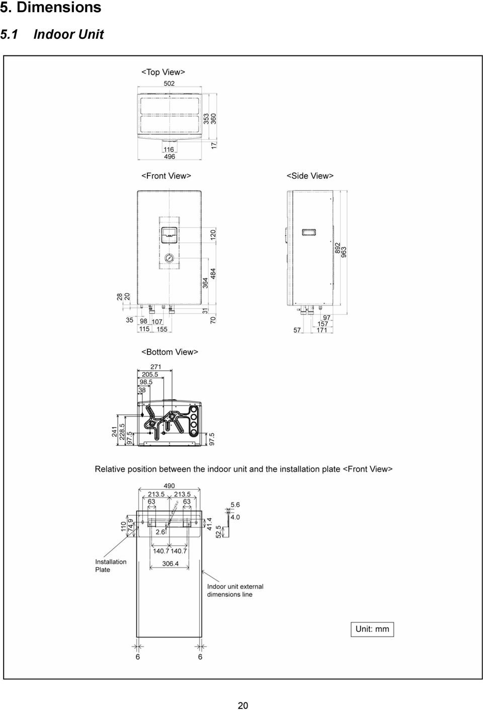
20 5. Dimensions 5.1 Indoor Unit 20
21 5.2 Outdoor Unit 21
22 6. Refrigeration and Water Cycle Diagram Model Gas Piping size Liquid Rated Length (m) Common Length (m) Max Elevation (m) Min. Piping Length (m) Max. Piping Length (m) Additional Refrigerant (g/m) UD09CE8 5/8 3/ UD12CE8 5/8 3/ UD14CE8 5/8 3/ UD16CE8 5/8 3/ * If piping length is over common length, additional refrigerant should be added as shown in the table. 22
23 23
24 7. Block Diagram 7.1 WH-UD09CE8 24
25 7.2 WH-UD12CE8 WH-UD14CE8 WH-UD16CE8 25
26 8. Wiring Connection Diagram 8.1 Indoor Unit WH-SDF09C3E8 26
27 8.1.2 WH-SDF12C9E8 WH-SDF14C9E8 WH-SDF16C9E8 27
28 8.2 Outdoor Unit 28
29 9. Electronic Circuit Diagram 9.1 Indoor Unit WH-SDF09C3E8 29
30 9.1.2 WH-SDF12C9E8 WH-SDF14C9E8 WH-SDF16C9E8 30
31 9.2 Outdoor Unit 31
32 10. Printed Circuit Board 10.1 Indoor Unit Main Printed Circuit Board 32
33 Solar Printed Circuit Board (Optional) 33
34 10.2 Outdoor Unit Main Printed Circuit Board 34
35 Noise Filter Printed Circuit Board 35
36 11. Installation Instruction 11.1 Select the Best Location Indoor Unit There should not be any heat source or steam near the unit. A place where air circulation in the room is good. A place where drainage can be easily done. A place where noise prevention is taken into consideration. Do not install the unit near the door way. Ensure the spaces indicated by arrows from the wall, ceiling, fence or other obstacles. Recommended installation height for indoor unit shall be at least 800 mm. Must install on a vertical wall. When install electrical equipment at wooden building of metal lath or wire lath, according to electrical facility technical standard, no electrical contact between equipment and building is allowed. Insulator must be installed in between. Do not install the unit at outdoor. This is designed for indoor installation only. When connecting solar pump station cable between indoor unit and solar pump station, the distance between both apparatuses shall be 2 ~ 8 meters and the length of the said cable must be shorter than 10 meter. Fail to do so may lead to abnormal operation to the system. Model SDF09C3E8/ UD09CE8 SDF12C9E8/ UD12CE8 SDF14C9E8/ UD14CE8 SDF16C9E8/ UD16CE8 Piping size Gas ø15.88 mm (5/8 ) Liquid Rated Length (m) Max Elevation (m) Min. Piping Length (m) Max. Piping Length (m) Additional Refrigerant (g/m) ø9.52 mm 5 ~ (3/8 ) ø15.88 ø9.52 mm (5/8 ) mm (3/8 ) 5 ~ ø15.88 mm (5/8 ) ø15.88 mm (5/8 ) ø9.52 mm 5 ~ (3/8 ) ø9.52 mm 5 ~ (3/8 ) Example: For SDF12C9E8/UD12CE8 If piping length is 40m, the quantity of additional refrigerant should be 500g. [(40-30)m x 50 g/m = 500g] 11.2 Indoor/Outdoor Unit Installation Diagram Outdoor Unit If an awning is built over the unit to prevent direct sunlight or rain, be careful that heat radiation from the condenser is not obstructed. Avoid location where ambient temperature is below -20 C. Keep the spaces indicated by arrows from wall, ceiling, fence or other obstacles. Do not place any obstacles which may cause a short circuit of the discharged air. If outdoor unit installed near sea, region with high content of sulphur or oilly location (e.g. machinery oil, etc), it lifespan maybe shorten. When installing the product in a place where it will be affected by typhoon or strong wind such as wind blowing between buildings, including the rooftop of a building and a place where there is no building in surroundings, fix the product with an overturn prevention wire, etc. (Overturn prevention fitting model number: K-KYZP15C) If piping length is over 30 m, additional refrigerant should be added as shown in the table. 36
CU-2E15LBE CU-2E18LBE CU-3E18LBE CU-4E23LBE
 Order No. PHAAM1003090C3 Outdoor Unit CU-2E15LBE CU-2E18LBE CU-3E18LBE CU-4E23LBE Air Conditioner Please file and use this manual together with the service manual for Model No. CS-E7LKEW CU-E7LKE CS-E7LKEW
Monobloc Air-to-Water Heatpump System
 Order No. PHAAM1010087C2 Monobloc Air-to-Water Heatpump System Monobloc Unit WH-MDF09C3E8 WH-MDF12C9E8 WH-MDF14C9E8 WH-MDF16C9E8 WARNING This service information is designed for experienced repair technicians
CS-CE9NKE CS-CE12NKE CU-CE9NKE CU-CE12NKE TABLE OF CONTENTS WARNING
 Order No: PAPAMY1207094CE Indoor Unit CS-CE9NKE CS-CE12NKE Outdoor Unit CU-CE9NKE CU-CE12NKE WARNING This service information is designed for experienced repair technicians only and is not designed for
TABLE OF CONTENTS. Air Conditioner. Indoor Unit Outdoor Unit CS-NE9MKE CU-NE9MKE CS-NE12MKE CU-NE12MKE CS-XE9MKE-5 CU-NE9MKE CS-XE12MKE-5 CU-NE12MKE
 Order No. PHAAM1107134C2 Air Conditioner Indoor Unit Outdoor Unit CS-NE9MKE CU-NE9MKE CS-NE12MKE CU-NE12MKE CS-XE9MKE-5 CU-NE9MKE CS-XE12MKE-5 CU-NE12MKE TABLE OF CONTENTS PAGE 1 Safety Precautions-----------------------------------------------
CS-XE9EKE CU-XE9EKE CS-XE12EKE CU-XE12EKE
 Order No. MAC0512111C8 Air Conditioner CS-XE9EKE CU-XE9EKE CS-XE12EKE CU-XE12EKE TABLE OF CONTENTS PAGE 1 Safety Precautions----------------------------------------------- 3 2 Specifications -----------------------------------------------------
CS-HE9NKE CS-HE12NKE CS-AE9NKE CU-HE9NKE CU-HE12NKE CU-AE9NKE TABLE OF CONTENTS WARNING
 Order No: PAPAMY1207093CE Indoor Unit CS-HE9NKE CS-HE12NKE CS-AE9NKE Outdoor Unit CU-HE9NKE CU-HE12NKE CU-AE9NKE WARNING This service information is designed for experienced repair technicians only and
CU-S9KKQ CU-S12KKQ CU-S18KKQ CU-S24KKQ CS-S9KKQ CS-S12KKQ CS-S18KKQ CS-S24KKQ WARNING
 Order No: PHAAM1001037C3 Indoor Unit CS-S9KKQ CS-S12KKQ CS-S18KKQ CS-S24KKQ Outdoor Unit CU-S9KKQ CU-S12KKQ CU-S18KKQ CU-S24KKQ WARNING This service information is designed for experienced repair technicians
Split-type Air-Conditioner INSTALLATION MANUAL CONTENTS FOR INSTALLER MXZ-3A30NA MXZ-4A36NA ATTENTION. English. Français. Español
 Split-type Air-Conditioner MXZ-3A30NA MXZ-4A36NA INSTALLATION MANUAL Refer to the installation manual of each indoor unit for indoor unit installation. English Français Español ATTENTION This manual mentions
TECHNICAL DATA & SERVICE MANUAL SPLIT SYSTEM AIR CONDITIONER INDOOR UNIT: AW52AL AW64AL AW52AL 387030095 AW64AL 0.8180.463.0 07/05
 TECHNICAL DATA & SERVICE MANUAL INDOOR UNIT: AW52AL AW64AL SPLIT SYSTEM AIR CONDITIONER Model No. Product Code No. AW52AL 387030095 AW64AL 387030096 0.8180.463.0 07/05 IMPORTANT! Please read before installation
Air Conditioner CU-XE9PKUA CU-XE12PKUA CS-XE9PKUA CS-XE12PKUA. Destination U.S.A. Canada WARNING
 Order No: PAPAMY1305056CE Air Conditioner Indoor Unit CS-XE9PKUA CS-XE12PKUA Outdoor Unit CU-XE9PKUA CU-XE12PKUA Destination U.S.A. Canada WARNING This service information is designed for experienced repair
HP switch LP switch Discharge thermo Comp. Surface thermo
 1 Specifications Zubadan Model Name PUHZ-SHW80VHA PUHZ-SHW11VHA PUHZ-SHW11YHA Power supply (phase, cycle, voltage) 1φ, V, Hz 1φ, V, Hz 3φ, 0V, Hz Max. current A 9.5 35.0 13.0 Breaker size A 3 16 Outer
ROOM AIR CONDITIONER INSTALLATION MANUAL
 ROOM AIR CONDITIONER INSTALLATION MANUAL ( Split Type) Please read this installation manual completely before installing the product When the power cord is damaged, replacement work shall be performed
AIR-CONDITIONER SPLIT TYPE
 FILE NO. A08-016 SERVICE MANUAL AIR-CONDITIONER SPLIT TYPE RAS-M10PKVP-E, RAS-M13PKVP-E, RAS-M16PKVP-E, RAS-M18PKVP-E / RAS-M10PKVP-ND, RAS-M13PKVP-ND, RAS-M16PKVP-ND, RAS-M18PKVP-ND / RAS-3M26GAV-E1,
Portable Air Conditioner
 Portable Air Conditioner Owner's Manual Model:3 in 1 12,000 Btu/h Series 3 Please read this owner s manual carefully before operation and retain it for future reference. CONTENTS 1. SUMMARY...1 2. PORTABLE
NewAir AC-10100E / AC-10100H Portable Air Conditioner Owner s Manual PLEASE READ AND SAVE THESE INSTRUCTIONS
 NewAir AC-10100E / AC-10100H Portable Air Conditioner Owner s Manual PLEASE READ AND SAVE THESE INSTRUCTIONS ELECTRICAL SAFETY This appliance is for indoor use only. Always turn off the unit and unplug
SWIMMING POOL HEAT PUMP
 SWIMMING POOL HEAT PUMP Installation & User Manual Model HP40B HP50B HP65B Hayward Pool Products Canada, Inc. T: 1-888-238-7665 www.haywardpool.ca CONTENT I. Application 4 II. Features 4 III. Technical
SERVICE MANUAL SPLIT SYSTEM ROOM AIR CONDITIONER SHARP CORPORATION SHARP CORPORATION CONTENTS
 SERVICE MANUAL SPLIT SYSTEM ROOM AIR CONDITIONER INDOOR UNIT AH-129 AH-MP14 OUTDOOR UNIT AU-129 AU-MP14 CONTENTS SPECIFICATIONS...2 EXTERNAL DIMENSIONS...4 WIRING DIAGRAMS...5 ELECTRICAL PARTS...6 MICROCOMPUTER
Air Conditioner CONTENTS CS-TE9DKE CU-TE9DKE CS-TE12DKE CU-TE12DKE. Order No. RAC0502005C2
 Order No. RAC0502005C2 Air Conditioner CS-TE9DKE CU-TE9DKE CS-TE12DKE CU-TE12DKE CONTENTS Page Page 1 Features 2 2 Functions 3 2.1. Remote Control 3 2.2. Indoor Unit 4 2.3. Outdoor unit 5 3 Product Specifications
AIR CONDITIONER INSTALLATION MANUAL
 INSTALLATION MANUAL AIR CONDITIONER Please read this installation manual completely before installing the product. Installation work must be performed in accordance with the national wiring standards by
SERVICE MANUAL. Room Air Conditioner Multi Split Wall-Mounted Type Indoor. FSAI-Pro-91AE2 FSAI-Pro-121AE2 FSAIF-Pro-181AE2
 SERVICE MANUAL Room Air Conditioner Multi Split Wall-Mounted Type Indoor FSAI-Pro-91AE2 FSAI-Pro-121AE2 FSAIF-Pro-181AE2 NOTE: Before servicing the unit, please read this at first. Always contact with
USER S MANUAL HSC-24A
 AIRREX AIR CONDITIONER USER S MANUAL HSC-24A Thank you for purchasing an AIRREX AIR CONDITIONER. BEFORE operation please read this user s manual carefully. Keep this manual readily available. It is ESSENTIAL
Air Conditioner Water Heater - A Product of HotSpot Energy LLC
 Air Conditioner Water Heater - A Product of HotSpot Energy LLC PLEASE READ THIS BEFORE YOU INSTALL THE UNIT 1. This air conditioner must be installed and/or repaired by a qualified technician. If you perform
MACBlower Model Number: MAC40R MAC60R MAC80R MAC100R. MAC120R MAC150R MAC 200R Serial # www.macblowers.com
 MACBlower Model Number: MAC40R MAC60R MAC80R MAC100R MAC120R MAC150R MAC 200R Serial # Fuji Clean USA 41-2 Greenwood Road Brunswick, Maine 04011 207-406-2729 www.macblowers.com MACBlowers The Intelligent
LG Floor Standing Type Air Conditioner INSTALLATION MANUAL
 website http://www.lgservice.com e-mail http://www.lgeservice.com/techsup.html LG Floor Standing Type Air Conditioner INSTALLATION MANUAL LG IMPORTANT Please read this installation manual completely before
SPLIT -TYPE ROOM AIR CONDITIONER
 Before using your air conditioner, please read this manual carefully and keep it for future reference SPLIT -TYPE ROOM AIR CONDITIONER Please read this installation manual completely before installing
Use and Care Manual. Model CPA12KH AIR CONDITIONER
 Use and Care Manual Model CPA12KH AIR CONDITIONER Introduction Thank you for choosing this air conditioner to provide you and your family with all of the "Home Comfort" requirements for your home, cottage
Floor Type Air-Conditioner INSTALLATION MANUAL CONTENTS FOR INSTALLER MFZ-KA25VA MFZ-KA35VA MFZ-KA50VA. English
 Floor Type Air-Conditioner MFZ-KA25VA MFZ-KA35VA MFZ-KA50VA INSTALLATION MANUAL This manual only describes the installation of indoor unit. When installing the outdoor unit, refer to the installation manual
ECOCIAT. Domestic hot water heat recovery unit
 Heat recovery unit Domestic hot water High energy efficiency with R410A Compact and quiet Scroll compressors Brazed-plate heat exchangers Heating Heat recovery ENVIRONMENTALLY HFC R410A PROTECTION DE FRIENDLY
Operating Instructions Split System Air Conditioner
 Operating Instructions Split System Air Conditioner Model No. Indoor Unit Type Indoor Unit Type Nominal Capacity 26 36 F2 Low Silhouette Ducted S-26PF2U6 S-36PF2U6 Connectable outdoor unit lineup This
Service manual. Website: www.andico.com.au CAUTION - BEFORE SERVICING THE UNIT, READ THE SAFETY - PRECAUTIONS IN THIS MANUAL.
 Website: www.andico.com.au Service manual CAUTION - BEFORE SERVICING THE UNIT, READ THE SAFETY - PRECAUTIONS IN THIS MANUAL. - ONLY FOR AUTHORISED SERVICE PERSONNEL. MODELS: MPK1-09CR-QB8 MPK1-12ER-QB6
NewAir AC-10000E, AC-10000H Portable Air Conditioner Owner s Manual PLEASE READ AND SAVE THESE INSTRUCTIONS
 NewAir AC-10000E, AC-10000H Portable Air Conditioner Owner s Manual PLEASE READ AND SAVE THESE INSTRUCTIONS BEFORE USE GENERAL SAFETY INSTRUCTIONS: ALWAYS OPERATE THE UNIT IN AN UPRIGHT POSITION AND PLACE
USER INSTRUCTIONS FOR GET PORTABLE 12k BTU AIR CONDITIONER MODEL No. GPACU12HR
 USER INSTRUCTIONS FOR GET PORTABLE 12k BTU AIR CONDITIONER MODEL No. GPACU12HR CONTENTS Introduction Safety Notes Identification of parts Installation instructions Operation instructions Maintenance Troubleshooting
Dehumidifier Users manual. For Models: DH45S DH65S
 Dehumidifier Users manual For Models: DH45S DH65S 950-0062-revD Jan. 9 2007 FORWARD The appearance of the units that you purchase might be slightly different from the ones described in the Manual, but
SECTION 15750 PACKAGED ROOFTOP AIR CONDITIONING UNITS
 SECTION 15750 PART 1 - GENERAL 1.01 DESCRIPTION A. Section includes requirements for roof mounted, self-contained units, with electric cooling, and electric or reverse refrigeration cycle (heat pump) heating
BUILT-IN DISHWASHER INSTALLATION INSTRUCTIONS
 BUILT-IN DISHWASHER INSTALLATION INSTRUCTIONS PLEASE READ COMPLETE INSTRUCTIONS BEFORE YOU BEGIN LEAVE INSTALLATION INSTRUCTIONS AND USER'S GUIDE WITH OWNER ALL ELECTRIC WIRING AND PLUMBING MUST BE DONE
INSTALLATION INSTRUCTIONS Fan Coil Replacement Coil Kit EBX & EBXX
 Fan Coil Replacement Coil Kit EBX & EBXX These instructions must be read and understood completely before attempting installation. These instructions covers the installation of replacement coil kit into
Reverse Cycle Inverter Split System Air Conditioner
 Reverse Cycle Inverter Split System Air Conditioner Model Number TAC-09CHSA/JAI5 INSTALLATION MANUAL Contents 03 Warranty Details 04 Welcome 05 General Safety Instructions 06 Product Overview 07 Selecting
technical data air conditioning systems RXS20-25-35E (single phase) FBQ-B8V1-B8V3B Split Heat Pump Condensing Units Split Sky Air
 FBQ-B8V1-B8V3B Split Heat Pump Condensing Units Split Sky Air") technical data RXS20-25-35E FBQ-B8V-B8V3B (single phase) Split Heat Pump Condensing Units air conditioning systems Split Sky Air Outdoor Units R-40A RXS-E2VB Split Sky Air Outdoor Units Features O u t
technical data RXS20-25-35E FBQ-B8V-B8V3B (single phase) Split Heat Pump Condensing Units air conditioning systems Split Sky Air Outdoor Units R-40A RXS-E2VB Split Sky Air Outdoor Units Features O u t
CEILING CASSETTE TYPE AIR CONDITIONERS INSTALLATION INSTRUCTIONS
 CEILING CASSETTE TYPE AIR CONDITIONERS INSTALLATION INSTRUCTIONS Please read this instruction sheet completely before installing the product. When the power cord is damaged, replacement work should be
Wall Mounted Mini Split Heat Pump Air Conditioner
 Wall Mounted Mini Split Heat Pump Air Conditioner OPERATING AND INSTALLATION MANUAL Model: KFIHP-09-ID / KFHIP-09-OD KFHHP-12-ID / KFHHP-12-OD Indoor Unit. Outdoor Unit. Thank you for selecting Soleus
1. BEFORE INSTALLATION
 ENGLISH SPLIT-TYPE AIR CONDITIONERS INSTALLATION MANUAL JG79A191H03 MSZ-GE06/09/12/15/18NA MSY-GE09/12/15/18NA When installing multi units, refer to the installation manual of the multi unit for outdoor
Operating Instructions Air Conditioner
 F566272 Operating Instructions Air Conditioner CS-C18FFH CS-C28FFH CU-C18FFH CU-C28FFH ENGLISH Before operating the unit, read these operating instructions thoroughly and keep them for future reference.
TABLE OF CONTENTS. Air Conditioner CS-E9HKEA CU-E9HKEA CS-E12HKEA CU-E12HKEA
 Order No. MAC0801090C2 Air Conditioner CS-E9HKEA CU-E9HKEA CS-E12HKEA CU-E12HKEA TABLE OF CONTENTS PAGE 1 Safety Precaution ------------------------------------------------ 2 2 Specifications -----------------------------------------------------
WINDOW ROOM AIR CONDITIONER
 WINDOW ROOM AIR CONDITIONER Installation and Operation Manual Electromechanical Remote Control CAPACITIES 220V - 60 HZ. 12,000; 18,000; 24000 BTU/HR 220V-240V - 50 HZ. 12,000; 18,000; 24000 BTU/HR Please
AIR CONDITIONER OUTDOOR UNIT
 AIR CONDITIONER OUTDOOR UNIT INSTALLATION MANUAL For authorized personnel only. MANUEL D'INSTALLATION Pour le personnel agréé uniquement. English Français MANUAL DE INSTALACIÓN Solo para personal autorizado.
AIR CONDITIONER OUTDOOR UNIT
 AIR CONDITIONER OUTDOOR UNIT INSTALLATION MANUAL For authorized personnel only. MANUEL D'INSTALLATION Pour le personnel agréé uniquement. English Français MANUAL DE INSTALACIÓN Solo para personal autorizado.
Si10-417_C. Pocket Manual. Service Diagnosis SPLIT & MULTI
 Pocket Manual Service Diagnosis SPLIT & MULTI Service Diagnosis SPLIT & MULTI 1. Troubleshooting with LED...5 1.1 Indoor Unit... 5 1.2 Outdoor Unit... 10 2. Troubleshooting by Symptoms...11 2.1 Air conditioner
14. Troubleshooting Guide
 14. Guide 14.1 Refrigeration Cycle System In order to diagnose malfunctions, ensure the air conditioner is free from electrical problems before inspecting the refrigeration cycle. Such problems include
OPTIONAL SLENDER REMOTE CONTROL
 DAIKIN ROOM AIR CONDITIONER Operation Manual OPTIONAL SLENDER REMOTE CONTROL BRC944A2B READ BEFORE OPERATION Safety Precautions...2 Names of Functions of Parts...4 Preparation before Operation...5 OPERATION
9ASNA-A1-1202 SERVICE MANUAL SENVILLE AIRCONDITIONER DC INVERTER SPLIT WALL-MOUNTED TYPE
 9ASNA-A1-1202 SERVICE MANUAL SENVILLE AIRCONDITIONER DC INVERTER SPLIT WALL-MOUNTED TYPE CONTENTS 1. Precaution... 1 1.1 Safety Precaution... 1 1.2 Warning... 1 2. Function... 6 3. Dimension... 9 3.1 Indoor
SECTION 23 81 03 - PACKAGED ROOFTOP AIR CONDITIONING UNITS NON-CUSTOM
 SECTION 23 81 03 - PACKAGED ROOFTOP AIR CONDITIONING UNITS NON-CUSTOM PART 1 - GENERAL 1.1 SUMMARY A. Section Includes: 1. Packaged rooftop air conditioning unit (5 tons and smaller). 2. Roof curb. 1.2
SWIMMING POOL HEAT PUMP Owners Manual
 SWIMMING POOL HEAT PUMP Owners Manual This manual refers to the 17.0kw and 21.0kw models only. The heat pump unit is sold with a 1 year warranty. In addition there is a 2 year parts warranty on the compressor
Portable Air Conditioner. OWNER S MANUAL Read these instructions before use. Model: MM14CCS. Voltage rating: 115V~60Hz Power rating : 1400W
 Portable Air Conditioner OWNER S MANUAL Read these instructions before use Model: MM14CCS Customer Support : 1-800-474-2147 Voltage rating: 115V~60Hz Power rating : 1400W For product inquiries or support
English DAIKIN ROOM AIR CONDITIONER INSTALLATION MANUAL. Français. R410A Split Series. Español MODELS FTXS15LVJU FTXS18LVJU FTXS24LVJU
 English DAIKIN ROOM AIR CONDITIONER INSTALLATION MANUAL R410A Split Series Español Français MODELS FTXS15LVJU FTXS18LVJU FTXS24LVJU Safety Precautions Read these Safety Precautions carefully to ensure
3. SEISCO PARTS & SERVICE REMOVAL AND REPAIR GUIDE
 4 3. SEISCO PARTS & SERVICE REMOVAL AND REPAIR GUIDE A. Changing the Control Board B. Replacing a Heating Element C. Thermistor Replacement D. High Limit Switch Replacement E. Level Detector Replacement
Portable Air Conditioner. OWNER S MANUAL Read these instructions before use. Model: MF08CESWW. Voltage rating: 115V~60Hz Power rating : 800W
 MODE ALARM Portable Air Conditioner OWNER S MANUAL Read these instructions before use 8 Model: MF08CESWW Voltage rating: 115V~60Hz Power rating : 800W Customer Support : 1-800-474-2147 For product inquiries
Operating Instructions Air Conditioner
 P07-T10130 Operating Instructions Air Conditioner Indoor Unit CS-F24DD1E5 CS-F28DD1E5 CS-F34DD1E5 CS-F43DD1E5 CS-F50DD1E5 Outdoor Unit Inverter Model (HBE5 Series) CU-YL24HBE5 CU-YL28HBE5 CU-YL34HBE5 CU-YL43HBE5
TECHNICAL & SERVICE MANUAL WINDOW TYPE AIR CONDITIONER SA 79G SA 99G FILE NO. SA 79G SA 99G REFERENCE NO. SM700402
 TECHNICAL & SERVICE MANUAL SA 79G SA 99G FILE NO. WINDOW TYPE AIR CONDITIONER Model No. Product Code No. Destination SA-79G-A 1 851 005 18 General (50Hz) & Europe SA-99G-A 1 851 005 19 SA 79G SA 99G REFERENCE
Portable Air Conditioner. OWNER S MANUAL Read these instructions before use. Model: MN12CES / MN10CESWW
 Portable Air Conditioner OWNER S MANUAL Read these instructions before use 8 Model: MN12CES / MN10CESWW Voltage rating: 120V~60Hz Power rating : 1100W (MN12CES) Power rating : 900W (MN10CESWW) Customer
AIR CONDITIONER INSTALLATION MANUAL
 FRANCAIS ESPAÑOL INSTALLATION MANUAL AIR CONDITIONER Please read this installation manual completely before installing the product. Installation work must be performed in accordance with the national wiring
ALL IN ONE. Heat Pump Water Heater
 ALL IN ONE Heat Pump Water Heater INSTALLATION AND OPERATION INSTRUCTIONS Please read this user s manual carefully before operate the unit. www.airtradecentre.com CONTENTS A. IMPORTANT REMARKS ------------------------------------------------------------------------------------------------
Installation and Troubleshooting Instructions for Electric Tankless Residential Water Heaters.
 Model Number: Serial Number: Information Manual Installation and Troubleshooting Instructions for Electric Tankless Residential Water Heaters. ATTENTION: IF YOU ARE NOT A LICENSED PLUMBER OR A LICENSED
SYSTEM Inverter Air Conditioners
 OPERATION MANUAL SYSTEM Inverter Air Conditioners MODEL Ceiling Suspended type FXHQ12MVJU FXHQ24MVJU FXHQ36MVJU Read these instructions carefully before installation. Keep this manual in a handy place
SERVICE INSTRUCTION R410A. WALL MOUNTEDtype INVERTER SPLIT TYPE ROOM AIR CONDITIONER. Models Indoor unit Outdoor unit
 SERVICE INSTRUCTION SPLIT TYPE ROOM AIR CONDITIONER WALL MOUNTEDtype INVERTER Models Indoor unit Outdoor unit ASYG07LECA ASYG09LECA ASYG12LECA ASYG14LECA AOYG07LEC AOYG09LEC AOYG12LEC AOYG14LEC R410A CONTENTS
USER INSTRUCTIONS FOR 10 LITRE PORTABLE DEHUMIDIFIER MODEL NO. DHMD102
 USER INSTRUCTIONS FOR 10 LITRE PORTABLE DEHUMIDIFIER MODEL NO. DHMD102 THANK YOU FOR CHOOSING YOUR NEW DEHUMIDIFIER. BEFORE USING THE UNIT READ THESE INSTRUCTIONS FULLY AND RETAIN THEM FOR FUTURE REFERENCE
Air Conditioner CONTENTS CS-V7DKE CU-V7DKE CS-V9DKE CU-V9DKE CS-V12DKE CU-V12DKE. Order No. MAC0412062C2
 Order No. MAC0412062C2 CS-V7DKE CU-V7DKE CS-V9DKE CU-V9DKE CS-V12DKE CU-V12DKE Air Conditioner CONTENTS Page Page 1 Features 3 2 Functions 4 2.1. Remote Control 4 2.2. Indoor Unit 5 2.3. Outdoor Unit 6
CELO5. User & Installation Manual. www.audac.eu
 CELO5 User & Installation Manual www.audac.eu 2 Introduction 5 High-end Slim Ceiling Speaker The CELO5 is the 5 version of AUDAC s CELO High-end Slim ceiling speaker series with an RMS power of 50 Watt
Portable Air Conditioner. OWNER S MANUAL Read these instructions before use. Model: MM14CHCSCS
 Portable Air Conditioner OWNER S MANUAL Read these instructions before use Model: MM14CHCSCS Voltage rating: 120V~60Hz Power rating : 1400W(Cooling) Power rating : 1350W(Heating) Customer Support : 1-800-474-21477
Ductless Split Air Conditioner
 Ductless Split Air Conditioner Installation Manual Indoor HSU09VHG(DB)-W HSU12VHG(DB)-W HSU18VHH(DB)-W HSU24VHG(DB)-W Outdoor HSU09VHG(DB)-G HSU12VHG(DB)-G HSU18VHH(DB)-G HSU24VHG(DB)-G Table of Contents
CONTENTS 1. IMPORTANT NOTICE 2 2. TECHNICAL SPECIFICATION 3 3. OPERATION DETAILS 4 4. ELECTRICAL SCHEMATIC DIAGRAM 13 5. EXPLOSION VIEW 16 6
 TCL WALL MOUNTED SPLIT-TYPE AIR CONDITIONERS SERVICE MANUAL No.TE080528 Models KFTHP-12 KFTHP-18 KFTHP-24 CONTENTS 1. IMPORTANT NOTICE 2 2. TECHNICAL SPECIFICATION 3 3. OPERATION DETAILS 4 4. ELECTRICAL
PORTABLE AIR CONDITIONER
 PORTABLE AIR CONDITIONER MAC 7500 Owner s Manual Air Conditioner Dehumidifier Oscillating Fan Please read this owner s manual carefully before operating the unit. POWERED BY 66126113.p65 17 INTRODUCTION
SHOWER WATER HEATER MODEL BS 35 / 45 / 60 BS 35 E / 45 E / 60 E OPERATION AND INSTALLATION INSTRUCTIONS
 SHOWER WATER HEATER MODEL BS 35 / 45 / 60 BS 35 E / 45 E / 60 E OPERATION AND INSTALLATION INSTRUCTIONS 2 This water heater must be installed (water and electrical installation), commissioned and serviced
FAN SPEED AIR SWING SET CANCEL FAN AIR SWING SET CANCEL WARNING
 AUT O HE AT COOL DRY AUT O HE AT COOL DRY FAN SP E ED FAN SPEED AC AC AIR SWING SE T CHE CK CLOCK RE SE T AIR SWING SE T CHE CK CLOCK RE SE T FAN SPEED AIR SWING RC RC Order No: PAPAMY32039CE (YE9/2QKE)
Hi Wall Split Air Conditioners
 R22 220-240V ~, 50Hz Hi Wall Split Air Conditioners 53KHET 12-18-24 Cool Only 53QHET 12-18-24 Heat Pump INSTALLATION MANUAL Carrier is committed to continuously improving its products according to national
INFRARED QUARTZ WALL HEATER
 INFRARED QUARTZ WALL HEATER MODEL NO: IQ2000 PART NO: 6939004 MOUNTING & OPERATION INSTRUCTIONS GC0715 INTRODUCTION Thank you for purchasing this CLARKE Infrared Wall Heater. Before attempting to use this
SERVICE MANUAL FOR 6535 SERIES TWO TON HIGH EFFICIENCY PACKAGED HEAT PUMPS
 SERVICE MANUAL FOR 6535 SERIES TWO TON HIGH EFFICIENCY PACKAGED HEAT PUMPS TABLE OF CONTENTS 1. Warnings...2 2. Accessibility Of Appliance...3 3. Unit Dimensions And Specifications...3 4. Unit Specifications
CONTENTS 1. IMPORTANT NOTICE 2 2. TECHNICAL SPECIFICATION 3 3. OPERATION DETAILS 4 4. WIRING DIAGRAM 11 5. EXPLOSION VIEW 12 6.
 TCL WALL MOUNTED SPLIT-TYPE AIR CONDITIONERS SERVICE MANUAL No.TE051220 Models TAC-09CHSA/GI TAC-12CHSA/GI CONTENTS 1. IMPORTANT NOTICE 2 2. TECHNICAL SPECIFICATION 3 3. OPERATION DETAILS 4 4. WIRING DIAGRAM
SERVICE MANUAL OUTDOOR UNIT. No. OBH590 REVISED EDITION-B. Models HFC
 SPLIT-TYPE AIR CONDITIONERS Revision B: MUZ-EF25/35/42/50VE - E2 and MUZ-EF25/35VEH - E2 have been added. Please void OBH590 REVISED EDITION-A. OUTDOOR UNIT SERVICE MANUAL HFC utilized R410A. OBH590 REVISED
DIGITAL SCROLL CENTRAL AIR CONDITIONER (OUTDOOR UNIT)
") E-II-YDS-100-140-0907 ENGLISH INSTALLATION MANUAL DIGITAL SCROLL CENTRAL AIR CONDITIONER (OUTDOOR UNIT) YDS System, R410A, R407C & R22 / YDMH-C (B/A) 100&140 For correct installation, read this manual
E-II-YDS-100-140-0907 ENGLISH INSTALLATION MANUAL DIGITAL SCROLL CENTRAL AIR CONDITIONER (OUTDOOR UNIT) YDS System, R410A, R407C & R22 / YDMH-C (B/A) 100&140 For correct installation, read this manual
SMD Rework Station TABLE OF CONTENTS
 SMD Rework Station Thank you for purchasing the Hakko 50B SMD Rework Station. The Hakko 50B is designed to solder and desolder surface mounted devices with hot air. Please read this manual before operating
OPL BASIC. Dosing System for Professional Laundry machines. Contents
 OPL BASIC Dosing System for Professional Laundry machines Contents 1 Getting Started. Page 2 2 Installation. Page 4 3 Set Up & Operation. Page 8 4 Maintenance & Accessories. Page 10 5 Troubleshooting Page
TECHNICAL & SERVICE MANUAL SPLIT SYSTEM AIR CONDITIONER + SAP C181MA + SAP C181GA + SAP C181BA + SAP C241MA + SAP C241BA FILE NO.
 TECHNICAL & SERVICE MANUAL SAP K161GJA SAP K181GJA SAP K181MBA SAP K241GJA SAP K241MBA + SAP C161GA + SAP C161JA + SAP C181GA + SAP C181JA + SAP C181MA + SAP C181BA + SAP C241GA + SAP C241JA + SAP C241MA
PORTABLE AIR CONDITIONER
 VERY IMPORTANT! MODEL: GDC-AC9RW / GDC-AC9RCS GDC-AC9RCW / GDC-AC12RW GDC-AC12RB / GDC-AC12RCB GDC-AC12RCW INSTRUCTIONS FOR USE PORTABLE AIR CONDITIONER Do not install and use your portable air conditioner
Ergo-Pro Single Line Solar Station Installation and Operating Instructions
 Rp 3/4 Ergo-Pro Single Line Solar Station Installation and Operating Instructions Item No Pump type 677.21.70 WILO ST 15/6 13 2 4 11 Technical Specifications Max. operating pressure: 6 bar Max. operating
UB1 AIR CONDITIONING UNIT INSTALLATION INSTRUCTIONS
 UB1 AIR CONDITIONING UNIT INSTALLATION INSTRUCTIONS INSTALLATION INSTRUCTIONS: Carefully read these instructions before installing your new air-conditioner. AUSTRALIAN AUTOMOTIVE AIR AL00500054E 1 Table
CS-PE9CKE CU-PE9CKE CS-PE12CKE CU-PE12CKE
 Order No. GMAC0401003C2 CS-PE9CKE CU-PE9CKE CS-PE12CKE CU-PE12CKE Room Air Conditioners CONTENTS Page 1 Functions 2 2 Product Specifications 5 3 Dimensions 9 4 Refrigeration Cycle Diagram 11 5 Block Diagram
USER S MANUAL FH052EAV1 FH070EAV1. System Air Conditioner (Cooling and Heating) ENGLISH ESPAÑOL FRANÇAIS ITALIANO PORTUGUÊS DEUTSCH E HNIKA
 ENGLISH ESPAÑOL FRANÇAIS ITALIANO PORTUGUÊS DEUTSCH E HNIKA") USER S MANUAL FH052EAV1 FH070EAV1 E HNIKA PORTUGUÊS ENGLISH ESPAÑOL ITALIANO DEUTSCH FRANÇAIS System Air Conditioner (Cooling and Heating) E S F I P D G DB98-29263A(1) Safety Precautions Register your
USER S MANUAL FH052EAV1 FH070EAV1 E HNIKA PORTUGUÊS ENGLISH ESPAÑOL ITALIANO DEUTSCH FRANÇAIS System Air Conditioner (Cooling and Heating) E S F I P D G DB98-29263A(1) Safety Precautions Register your
DUCTED SPLIT TYPE AIR CONDITIONERS INSTALLATION INSTRUCTIONS
 LN-IM-01 DUCTED SPLIT TYPE AIR CONDITIONERS INSTALLATION INSTRUCTIONS Please read this instruction sheet completely before installing the product. When the power supply location is wanted to replace, replacement
HEAT PUMP FREQUENTLY ASKED QUESTIONS HEAT PUMP OUTDOOR UNIT ICED-UP DURING COLD WEATHER:
 HEAT PUMP FREQUENTLY ASKED QUESTIONS HEAT PUMP OUTDOOR UNIT ICED-UP DURING COLD WEATHER: It is normal for a heat pump to have a build up of white frost on the outside coil during cold damp weather. The
Cooling system components, removing and installing
 Engine BHW Cooling system components, removing and installing Page 1 / 24 19-1 Cooling system components, removing and installing Warning! When doing any repair work, especially in the engine compartment,
AIR CONDITIONER (SPLIT TYPE)
") OWNER S MANUAL AIR CONDITIONER (SPLIT TYPE) For general public use ENGLISH EN Indoor Unit RAS-07PKVP-E RAS-10PKVP-E RAS-13PKVP-E RAS-16PKVP-E RAS-18PKVP-E RAS-07PKVP-ND RAS-10PKVP-ND RAS-13PKVP-ND RAS-16PKVP-ND
OWNER S MANUAL AIR CONDITIONER (SPLIT TYPE) For general public use ENGLISH EN Indoor Unit RAS-07PKVP-E RAS-10PKVP-E RAS-13PKVP-E RAS-16PKVP-E RAS-18PKVP-E RAS-07PKVP-ND RAS-10PKVP-ND RAS-13PKVP-ND RAS-16PKVP-ND
CENTRAL AIR CONDITIONER SPLIT SYSTEM
 CENTRAL AIR CONDITIONER SPLIT SYSTEM WITH ELECTRONIC CONTROL SERIES BS BS 30E BS 36 BS 43 INSTALLATION INSTRUCTIONS SUMMARY GENERAL...3 SELECTING THE LOCATION OF UNITS...5 RELATIVE LOCATION OF THE UNITS...5
Geyser-R Heat pump water heater Installation manual
 Geyser-R Heat pump water heater Installation manual 1 Version 2.9 SAFETY INFORMATION Please read carefully to prevent serious accidents or injury. The Geyser-R Heat Pump Water Heater must be installed
Bench Autoclave. Standard Operating Procedure. For Installation, Use and Maintenance
 Bench Autoclave Standard Operating Procedure For Installation, Use and Maintenance 1. Introduction This SOP is intended for use with the following model, in a laboratory context: Type: Nuve Bench Top Steam
Heat Pump Water Heater IOM Manual
 Heat Pump Water Heater IOM Manual Installation Operation & Maintenance This manual is intended as an aid to qualified service personnel for proper installation, operation and maintenance of the heat pump
CEILING CASSETTE FAN COIL UNIT
 CEILING CASSETTE FAN COIL UNIT Operation and Installation Manual MHCFC4W-04, 08, 12, 16 Four way ceiling cassette fan coil unit Please read this manual before using the fan coil unit. Installation and
Room Air Conditioners
 Installation Manual Room Air Conditioners R410A Split Type Y Series DC INVERTER ECO940SD ECO1240SD ECO1840SD Please read this installation manual completely before installing the product. When the power
REGULINE 600VA / 1000VA REGULATOR USER MANUAL
 REGULINE 600VA / 1000VA REGULATOR USER MANUAL TUNÇMATİK REGULINE SERIES AUTOMATIC VOLTAGE REGULATOR Models: REGULINE 600VA / REGULINE 1000VA Principle of Operation Automatic Voltage Regulators regulate
Air Conditioners Technical Data
 Air Conditioners Technical Data O u t d o o r U n i t E E D E N 2-0 0 RX-JV Outdoor Unit RX-JV TABLE OF CONTENTS RX-JV Features............................................................. 2 2 Specifications.......................................................
SPLIT TYPE ROOM AIR CONDITIONER INSTALLATION INSTRUCTION SHEET
 SPLIT TYPE ROOM AIR CONDITIONER INSTALLATION INSTRUCTION SHEET (PART NO. 97474700) For authorized service personnel only. This installation instruction sheet describes how to install the outdoor unit only.