Homebrewing for QRP SSB
|
|
|
- Marybeth Dennis
- 7 years ago
- Views:
Transcription
1 Homebrewing for QRP SSB First I would like to mention my website or in case you forget the site URL, just google my call sign N6QW. Many of my projects are documented there, complete with schematics and links to hints and tips that maybe helpful if you are contemplating building a homebrew QRP SSB transceiver. As an aside I have formally documented much of what we will discuss in this podcast and that document will be up on my website so you can download the circuits and details. Homebrewing a QRP SSB transceiver is a very interesting subject and one that often scares homebrewers who would like to move from the less complex CW transceiver to ones where a rag chew is something other than a blur of sounds at 35 WPM. But the changes necessary to transition to a homebrew QRP SSB transceiver are not that great and can be readily accomplished if the design is thought of in terms of a process. You will hear me talk a lot about process and processes. The very 1 st step in any homebrew process is to be prepared for the project and that perhaps is the very thing that determines whether your project is successful or sorta kinda worked once. There is no rocket science to the preparation phase just some logical thinking and below is my list of things that need to be in place: Reference library, much of which can be found on the internet. But that also includes setting up your filing system on your computer so that the data can be readily accessed. I have folders on my computer that include spec sheets for my favorite devices, articles and documentation from others as well as information on my projects Basic test equipment including a wide range crystal test oscillator, RF probe, DVM, 0-1 amp DC meter, signal source like a DDS. An Oscilloscope is really handy and almost a necessity. An LC meter such as available from AADE is another handy item that once you have you wonder why you waited so long to get one.

2 Basic tools such as a temperature controlled grounded soldering iron with interchangeable fine tips, good quality needle nose pliers, various screwdrivers, exacto knife, tweezers and LED flashlight. Junque Box. Purchase parts in bulk and save big time. I purchase 2N3904 and 2N3906 resistors typically for 3 cents a piece buying 100 at a time. Many parts seem to show up over and over again like 100NF and 10NF capacitors, 1N4148 diodes, LM386 audio amps, NE5534 s op amps, 2N2219 (good cheap RF transistor), ferrite cores such as the FT 37-43, iron cores such as T-37-6, T50-6, T68-6, T68-2, etc. See where most of these common parts have been identified. As a prelude to Homebrewing a QRP SSB transceiver, one of the most critical elements is the choice of IF (Intermediate Frequency) since most of the less complex designs are single conversion. This is where some time spent with a calculator can pay off big dividends. Typically (for very good technical reasons) both commercial and homebrew filters are in the range of 3 to 12 MHz. Thus to operate on the ham bands means that the LO (local oscillator) when mixed with the incoming signal results in the IF frequency. 9.0 MHz has been a popular IF frequency and when you mix that with a 5.0 MHz LO results in either 80 Meters ( = 9) or 20 Meters ( = 9). So one can get two bands with one filter and one LO the band switching of course has to include the proper band pass filters so that only the band selected is received. But that choice of 9.0 MHz is not ideal for 17 Meters as the LO would have to be on about the same frequency as the IF. This presents all sorts of mixing problems. [Mixing problems arise where harmonics of oscillators or frequency generating circuits fall within amateur (or commercial bands) other than the one intended. This will make the FCC very unhappy.] In looking at the design of the Elecraft K2, I noticed the designer s picked MHz for the IF frequency. Well that lit a big bulb for me. With that IF, which happens to be a standard computer crystal frequency that can be had for less than 50 cents each, there are many more possibilities for the ham bands. If you took several MHz computer crystals and built a Super VXO which means you can actually vary that crystal frequency over

3 a fairly wide range and then pass that signal through a diode doubler circuit where the resulting signal is MHz rock solid stable. Now = which is right in the middle of the 17 Meter SSB band. If you take that same VXO concept using a MHz VXO and mix that with a crystal you get = MHz you now are on 20 Meters. A crystal gives you The MHz VXO typically has about a 30 KHz spread so you can have a 60 khz or more slice of the 20 Meter phone band. All of these crystals are stock computer crystals that typically cost less than 50 cents each. [I used this approach in four different QRP SSB radios and can attest it works!] Homebrew crystal filters entail a small amount of effort and this is where the first use of the test oscillator comes into play. For a four pole filter it is a good idea to purchase 10 crystals on the same frequency as you want to find at least 4 that are very close in frequency. You might get lucky and actually get two filters. Of the remaining crystals at least one will be enough off frequency to be suitable for the BFO/CIO. You can use a general coverage receiver to listen to the test oscillator with each crystal plugged into the oscillator. Pick the ones that sound closest in frequency. With a little practice this can be done quite accurately. If your receiver has a digital display it will tell you exactly the frequencies. I happen to have a frequency counter and thus it is a simple matter of reading the frequencies. For a four pole filter you will need 5 coupling caps of the same value. Typically the smaller the caps the wider the filter bandwidth. At around PF the filter will be good for SSB and 300 to 470 PF is best for CW. The input output impedance of the filter is in the range of 200 to 400 ohms. I usually assume 200 ohms as it is an easy 4:1 match to 50 Ohms. There are rigorous calculations and simulations that will give you precise values but my empirical try it and go is probably fairly close to the calculated values. A word here about sideband inversion and frequency mixing schemes. Homebrew ladder type filters (the crystals are all of the same value) tend to favor Lower Sideband (LSB). So when you place the Local Oscillator above the incoming signal such as we have with our 17 and 20 Meter example, the subtractive mix of the LO minus the incoming signal results in what is called a sideband inversion. Thus the subtractive mix is on LSB. This is FB because with a filter favoring lower sideband and using a BFO on the LSB

4 side demodulates the signal as an Upper Sideband (USB) signal. So this is good fortune. I always like to start a project with a block diagram and then simply fill in the blocks with my favorite circuits. Oh, when I actually build the project I start at the back end and work my way forward. This approach enables me to use the project itself to test as I build and should something not work I know exactly where the problem is and do not proceed any further until it is resolved. I should mention that I also have developed standard building blocks that I simply reuse in my projects. I know they work and I know their level of performance. Let us take an example: The next photo is of two transceivers I built which are basically the same circuit with the smaller one being the second build. The block diagram for these radio is shown below. The variation between the 1 st and 2 nd build is the second does not have an Rx RF amp stage and a different RF output stage. These changes were to conserve space and enable making the second one about 1/3 the cubic size of the 1 st.

5 This is a block diagram of a 20 Meter QRP SSB transceiver that could fit in your shirt pocket. Much time was spent on this block diagram in a process I call noodling, that is thinking about the topology and how to make this an efficient design while at the same time making it physically small. So the first thing to be done is to not heat up the soldering iron but spend some time doing research and collecting information. Once that is done then it is a matter of finding circuits that will work in the blocks. This also is a really good time to think about how the final package will look. I learned that the hard way when I built a tri-band QRP SSB transceiver using the filter and frequency scheme from the Heathkit HW-100. I usually bread board all of the radios using a piece of 2 X 2 plywood and that forms the base for temporarily installing circuit boards and thus the radio is tested out in the open and then packaged. Here is what the bread board looked like for that project. Once I was at this stage I knew I was in trouble as I hadn t really thought about the final box. Spend some time on this first. BTW I actually made QSO s with this breadboard radio!

6 The build process then as previously stated starts at the back end by building the audio amplifier and microphone amplifier stages using designs that I have found really work and involve commonly available parts no exotic unobtanium parts here! Shown below is the design for these two stages and the beauty is that once built they can be tested and debugged. Thus you know that these are viable circuits and are working!

7

8 The finished circuit board is shown below and involved the use of single sided copper vector board (read expensive) and was a challenge to build. This board was mounted physically near the back panel of the radio and a 5/16 inch hole was drilled in the back panel so a small screwdriver could be inserted in the hole and aligned with the small trim pot yes that is the microphone gain control. The only reason I mention this is that front panel space actually dictated the final size and there was no room for a microphone gain control on the front panel. But I had to think about this before I turned on the soldering iron!

9 Oh, I have very sophisticated test process for these two circuits. Once built I start with the audio amp and after hooking up power, gain control and a 8 ohm speaker taking a metal screwdriver I simply touch the input pin on the 2N3904 big hum I know it works. Adjusting the audio gain control should have control of the hum and that the control wires give max gain in the CW direction. Now I power up the microphone amp in addition to the audio amp using the same procedure touching the input pin of the NE5534 should result in a loud squeal adjusting the 50K should show that the microphone gain works.

10 The next block is the BFO/CIO and combination product detector / balanced modulator. That schematic is shown below. A comment here about the choice of DBM (Double Balanced Mixer) the ADE1-L. It was chosen because it is small, an SMD part, and is a 4 dbm device meaning it only needs 1.0 Volt Pk to Pk to drive it. Here is where some time spent researching can pay big dividends. The ADE1-L is built by mini-circuits labs. At the time I bought these the price for a single unit was close to $16. If you bought three that would be $48. But if you bought 10 the price was under $4 each. So if you bought 12 ($48) that is the same price if you only bought 3. I still have a couple of units in my junk box that are being reserved for the next project! The photo below shows the next two blocks during the construction process with the circuits on the right side being the CIO/BFO and the PD/BM. Once this part of the circuit was built its output was connected to the audio amp module and then using a signal near MHz (nothing more than a one transistor test oscillator tuned slightly off of the BFO/CIO frequency) and then a beat note can be heard coming from the speaker. Now it was clear that these four elements were working. The circuit board on the left side is the bilateral amp stages and behind that the home brew
 that is the same price if you only bought 3.")
11 crystal filter. Again the same process of building and then a temporary hookup and test. Using that same test oscillator these two stage and the filter can be checked as you move the test oscillator through the stages the sound from the speaker should get louder any stage where it doesn t then you know where the problem is. The schematic for the left side is shown below:

12 The next several blocks, consisting of the Rx Tx mixer, another ADE1-L, the switched crystal VXO and the 20 Meter Band Pass Filter. The width and height is 2 inches so a lot of parts in a small area. Thus the noodling process has to take place first before heating up the iron.

13 The schematic for this part of the build is shown below. Again these circuits once built can be connected to the already working circuits and the test process here is to inject a MHz signal into the BPF and it should be clearly heard in the audio output.

14

15 Spend some time now getting acquainted with the receiver by optimizing the Band Pass Filter for the portion of the band being worked and there may need to be some adjustment of the BFO/CIO frequency so that it is placed on the proper portion of the filter slope. This is also an opportunity to see how well it hears in terms of sensitivity. As the old adage says if you can hear them you can work them. There are several you tube videos which can be found by searching under N6QW and you can hear the two versions of this radio it hears quite well! The 1 st version is more sensitive as it has an RF amp stage but one feature is missing since this project was entirely designed with the idea of miniaturization. No AGC and on occasion really strong signals with the RF amp version WILL overload. Backing off on the audio gain does help. The second version without the Rx RF amp will not overload as much. So adding an AGC would help but that requires more space. PD7SSB on seeing this design added an audio AGC circuit which helps. So that is yet more opportunity for experimentation.

16 On both versions the circuit black which gave me the most headaches or as some know heartburn, was the transmitter RF amp stages. This is where one really has to pay attention to circuit layout, unwanted coupling, shielding and heat sinks. In the second version which uses a slightly different final brick the problem was heat. The final is an IRF510 and the final bias made it more than warm to the touch if you wanted max smoke! I tried several of the TO-220 style heatsinks and none were really adequate. Finally I tried using a slab of copper on the back side of the circuit board in addition to the TO-220. In the local hardware store there were heavy duty copper fittings such as are used on grounding cables for house wiring. I found a fitting and smashed it flat in a vise and drilled a hole in the middle to attach to the IRF510. Copper is a much better heatsink than aluminum. Many of the high power RF amplifiers use a copper spreader between the device and the aluminum heatsink so I just borrowed the idea. The circuits for the smaller version came form EMRFD! The larger version of the radio used a different RF chain which was physically too big to fit in the space available so it was not used. That said it does produce more power by again the same attention to detail on

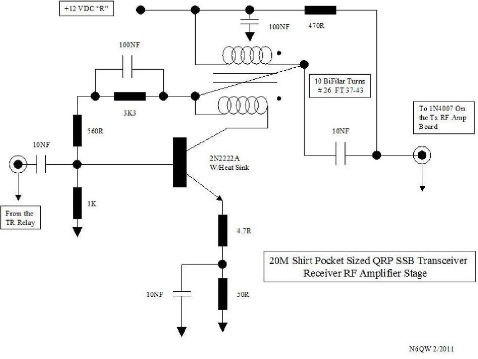
17 unwanted coupling, shielding, and heat sinks was very much the same considerations. This version has the Receiver RF amplifier stage and note that diode steering was used to route signals between transmit and receive to/from the common band pass filter network. The 2N2222 is biased hot and needs a heatsink. In the photo you can see that the circuit elements are very tight and the use of single sided copper vector board enables a common ground plane so ground loops are not so much of a concern. This approach enables solder shielding directly to the copper surface and it made the task so much easier.

18
19

20 A special not here about version two and the concept of a copper spine down the center with many shielded compartments. This is not original work but thanks in large measure to Allison KB1GMX who shared this approach with me. It really works and affords a compact final product with more than adequate circuit isolation and a good deal of surface area to remove heat. Yes some of the circuits do get hot to the touch. In fact in version one after building the enclosure I had to go back and cut a vent hole in the top of the case!

21
22
23
24
Homebuilt HF Radios for Use Underground Paul R. Jorgenson KE7HR
 Homebuilt HF Radios for Use Underground Paul R. Jorgenson KE7HR With the good success in using Amateur Band HF radio for underground communications, I started looking for cheaper alternatives to the $500+
Cumbria Designs T-1. SSB/CW Filter kit (4.9152MHz) User Manual
 User Manual") Cumbria Designs T-1 SSB/CW Filter kit (4.9152MHz) User Manual CONTENTS 1 INTRODUCTION 2 2 CIRCUIT DESCRIPTION 2 3 ASSEMBLY 2 4 TESTING 4 The Steading Stainton PENRITH Cumbria CA11 0ES UK 1 Introduction
Cumbria Designs T-1 SSB/CW Filter kit (4.9152MHz) User Manual CONTENTS 1 INTRODUCTION 2 2 CIRCUIT DESCRIPTION 2 3 ASSEMBLY 2 4 TESTING 4 The Steading Stainton PENRITH Cumbria CA11 0ES UK 1 Introduction
A CW QRP Transceiver for 20 m band. How it works I'll describe individually the three boards and the relative tuning devices.
 A CW QRP Transceiver for 20 m band The little QRP presented in this article may be built in a gradual manner, in fact it is divided in two main modules (plus VFO), you may also complete only a single part
Modifying the Yaesu FT-847 External 22.625 MHz Reference Input
 Modifying the Yaesu FT-847 External 22.625 MHz Reference Input David Smith VK3HZ Introduction This document describes the modification of an FT-847 to allow an external 22.625 MHz Reference oscillator
One Stage Superheterodyne Receiver with the SA602N integrated Circuit
 One Stage Superheterodyne Receiver with the SA602N integrated Circuit If you ever dreamt of building a superheterodyne receiver, now you have the possibility of bringing to reality...your dream! And this
Germanium Diode AM Radio
 Germanium Diode AM Radio LAB 3 3.1 Introduction In this laboratory exercise you will build a germanium diode based AM (Medium Wave) radio. Earliest radios used simple diode detector circuits. The diodes
AM TRANSMITTERS & RECEIVERS
 Reading 30 Ron Bertrand VK2DQ http://www.radioelectronicschool.com AM TRANSMITTERS & RECEIVERS Revision: our definition of amplitude modulation. Amplitude modulation is when the modulating audio is combined
200W DISCRETE POWER AMPLIFIER K8060
 H8060IP-1 200W DISCRETE POWER AMPLIFIER K8060 Ideal for active speaker system or subwoofer, guitar amp, home theatre systems, instrument amp, etc. Features & Specifications Specifications: Excellent value
G4HUP Panoramic Adaptor Installation FT847
 G4HUP Panoramic Adaptor Installation FT847 These instruction cover installation of the PAT board in the 1st IF of the FT847 45.705MHz this gives access to all receiver options on the main receiver. A a
The RSGB Centenary Receiver Project Construction Manual
 The RSGB Centenary Receiver Project Construction Manual Page 1 of 12 Introduction This project is intended for those new to radio construction. It is a fairly simple receiver for the 14MHz (20m) amateur
Implementing the X-Lock-3 on the Heathkit HW-101
 Implementing the X-Lock-3 on the Heathkit HW-101 Pete Juliano, N6QW radioguy90@hotmail.com I had previously installed the X-Lock-2 in a Ten Tec Corsair I and a TR-7. Subsequently I installed an X-Lock-3
MAINTENANCE & ADJUSTMENT
 MAINTENANCE & ADJUSTMENT Circuit Theory The concept of PLL system frequency synthesization is not of recent development, however, it has not been a long age since the digital theory has been couplet with
HP 8970B Option 020. Service Manual Supplement
 HP 8970B Option 020 Service Manual Supplement Service Manual Supplement HP 8970B Option 020 HP Part no. 08970-90115 Edition 1 May 1998 UNIX is a registered trademark of AT&T in the USA and other countries.
A Low Frequency Adapter for your Vector Network Analyzer (VNA)
") Jacques Audet, VE2AZX 7525 Madrid St, Brossard, QC, Canada J4Y G3: jacaudet@videotron.ca A Low Frequency Adapter for your Vector Network Analyzer (VNA) This compact and versatile unit extends low frequency
Jacques Audet, VE2AZX 7525 Madrid St, Brossard, QC, Canada J4Y G3: jacaudet@videotron.ca A Low Frequency Adapter for your Vector Network Analyzer (VNA) This compact and versatile unit extends low frequency
Single Transistor FM Transmitter Design
 Single Transistor FM Transmitter Design In telecommunications, frequency modulation (FM) conveys information over a carrier wave by varying its frequency. FM is commonly used at VHF radio frequencies for
Kit 106. 50 Watt Audio Amplifier
 Kit 106 50 Watt Audio Amplifier T his kit is based on an amazing IC amplifier module from ST Electronics, the TDA7294 It is intended for use as a high quality audio class AB amplifier in hi-fi applications
K8025 VIDEO PATTERN GENERATOR. Check the picture quality of your monitor or TV, ideal for adjustment or troubleshooting.
 K8025 ILLUSTRATED ASSEMBLY MANUAL H8025IP 1 VIDEO PATTERN GENERATOR Check the picture quality of your monitor or TV, ideal for adjustment or troubleshooting. Forum Participate our Velleman Projects Forum
The front end of the receiver performs the frequency translation, channel selection and amplification of the signal.
 Many receivers must be capable of handling a very wide range of signal powers at the input while still producing the correct output. This must be done in the presence of noise and interference which occasionally
TROUBLESHOOTING RECEIVERS
 TROUBLESHOOTING RECEIVERS The four methods of troubleshooting are: 1. Circuit Disturbance 2. Signal Substitution 3. Signal Tracing 4. Measurement of Circuit Parameters Definition of Terms: Circuit Disturbance
Alpha 10 SERVICE MANUAL. Downloaded from www.cbradio.nl. MAX 10 Meter Amateur Transceiver AM/FM/CW/SSB 6 BAND PROGRAMMABLE MODEL AM-1000.
 Alpha 10 MAX 10 Meter Amateur Transceiver MODEL AM-1000 AM/FM/CW/SSB 6 BAND PROGRAMMABLE SERVICE MANUAL Downloaded from www.cbradio.nl Cover Page LOUDER TALKBACK MOD Alpha 10 Max - Model AM-1000 4.7K Resistor
THE R551N RECEIVER FAQ FAULT FINDING THE REDIFON COMMUNICATIONS RECEIVER R551N. Date: October 10th 1995 by: Jan Verduyn G5BBL
 THE R551N RECEIVER FAQ FAULT FINDING THE REDIFON COMMUNICATIONS RECEIVER R551N Introduction: Date: October 10th 1995 by: Jan Verduyn G5BBL Recently a number of Redifon R551N receivers have appeared on
SUPER SNOOPER BIG EAR
 AA-1D Super Snooper Big Ear SPECIFICATIONS Operates on 5 to 9v DC Will drive a small speaker Provides up to 1 watt of audio power Distortion > 0.2% Voltage Gain up to 46 db Size: 1 x 1.95 Rainbowkits.com
DL-QRP-AG Lambda/2 no Counterpoise: Fuchs Antenna matching unit
 DL-QRP-AG Lambda/2 no Counterpoise: Fuchs Antenna matching unit QRPproject Molchstr. 15 12524 Berlin http://www.qrpproject.de Telefon: +49(30) 85 96 13 23 e-mail: support@qrpproject.de Handbucherstellung:
The basic set up for your K2 to run PSK31 By Glenn Maclean WA7SPY
 The basic set up for your K2 to run PSK31 By Glenn Maclean WA7SPY I am by no means an expert on PSK31. This article is intended to help someone get on PSK31 with a K2. These are the things I did to get
Assembly Instructions: Shortwave Radio Kit
 Assembly Instructions: Shortwave Radio Kit MTM Scientific, Inc P.O. Box 522 Clinton, MI 49236 U.S.A Introduction Fig 1: The assembled Shortwave Radio Kit The SHORTWAVE RADIO KIT (#SWRAD) from MTM Scientific
AUTOMATIC CALL RECORDER JAMECO PART NO. 2163735
 AUTOMATIC CALL RECORDER JAMECO PART NO. 2163735 Experience Level: Intermediate Time Required: 1-2 Hours This project automatically records phone calls. The program, along with the adapter records each
Constructing a precision SWR meter and antenna analyzer. Mike Brink HNF, Design Technologist.
 Constructing a precision SWR meter and antenna analyzer. Mike Brink HNF, Design Technologist. Abstract. I have been asked to put together a detailed article on a SWR meter. In this article I will deal
POCKET AUDIO GENERATOR K8065
 POCKET AUDIO GENERATOR K8065 Great little gadget for service repair, testing, education, etc... ILLUSTRATED ASSEMBLY MANUAL H8065IP-1 VELLEMAN NV Legen Heirweg 33 9890 Gavere Belgium Europe www.velleman.be
Modulation Methods SSB and DSB
 Modulation Methods SSB and DSB William Sheets K2MQJ Rudolf F. Graf KA2CWL SSB or Single Sideband, is a type of AM without the carrier and one sideband. DSB or double sideband is AM with the carrier suppressed,
K2570 UNIVERSAL POWER SUPPLY 5-14DC / 1A. The easy way to power your ILLUSTRATED ASSEMBLY MANUAL
 Total solder points: 18 Difficulty level: beginner 1 2 3 4 5 advanced UNIVERSAL POWER SUPPLY 5-14DC / 1A K2570 The easy way to power your projects. ILLUSTRATED ASSEMBLY MANUAL H2570IP-1 Features & Specifications
Audio processing and ALC in the FT-897D
 Audio processing and ALC in the FT-897D I recently bought an FT-897D, and after a period of operation noticed problems with what I perceived to be a low average level of output power and reports of muffled
ECEN 1400, Introduction to Analog and Digital Electronics
 ECEN 1400, Introduction to Analog and Digital Electronics Lab 4: Power supply 1 INTRODUCTION This lab will span two lab periods. In this lab, you will create the power supply that transforms the AC wall
Introduction to Receivers
 Introduction to Receivers Purpose: translate RF signals to baseband Shift frequency Amplify Filter Demodulate Why is this a challenge? Interference (selectivity, images and distortion) Large dynamic range
UNDERSTANDING AND CONTROLLING COMMON-MODE EMISSIONS IN HIGH-POWER ELECTRONICS
 Page 1 UNDERSTANDING AND CONTROLLING COMMON-MODE EMISSIONS IN HIGH-POWER ELECTRONICS By Henry Ott Consultants Livingston, NJ 07039 (973) 992-1793 www.hottconsultants.com hott@ieee.org Page 2 THE BASIC
LM 358 Op Amp. If you have small signals and need a more useful reading we could amplify it using the op amp, this is commonly used in sensors.
 LM 358 Op Amp S k i l l L e v e l : I n t e r m e d i a t e OVERVIEW The LM 358 is a duel single supply operational amplifier. As it is a single supply it eliminates the need for a duel power supply, thus
DX 2517. AM FM SSB CW PA Amateur Base Station Transceiver OWNER S MANUAL RX / TX 2 4 POWER NF CHANNEL MODE RF POWER OFF CAL OFF OFF CALIBRATE
 1 2 3 6 4050 ULA 6070 TI 80 90 100 9 DX 2517 2517 RX / TX 0 2 4 SWR WATTS SET 81012 22 1 010 3 2030 5 MOD 7 ON dbover 9 SIGNAL +20 +40+60 PA FM AM USB LSB CW POWER ON SWR NB / ANL R.BEEP +10KHz NF CHANNEL
Build A Video Switcher. Reprinted with permission from Electronics Now Magazine September 1997 issue
 Build A Video Switcher Reprinted with permission from Electronics Now Magazine September 1997 issue Copyright Gernsback Publications, Inc.,1997 BUILD A VIDEO SWITCHER FRANK MONTEGARI Watch several cameras
11: AUDIO AMPLIFIER I. INTRODUCTION
 11: AUDIO AMPLIFIER I. INTRODUCTION The properties of an amplifying circuit using an op-amp depend primarily on the characteristics of the feedback network rather than on those of the op-amp itself. A
Application Note SAW-Components
 Application Note SAW-Components Principles of SAWR-stabilized oscillators and transmitters. App: Note #1 This application note describes the physical principle of SAW-stabilized oscillator. Oscillator
Physics 3330 Experiment #2 Fall 1999. DC techniques, dividers, and bridges R 2 =(1-S)R P R 1 =SR P. R P =10kΩ 10-turn pot.
R P R 1 =SR P. R P =10kΩ 10-turn pot.") Physics 3330 Experiment #2 Fall 1999 DC techniques, dividers, and bridges Purpose You will gain a familiarity with the circuit board and work with a variety of DC techniques, including voltage dividers,
Physics 3330 Experiment #2 Fall 1999 DC techniques, dividers, and bridges Purpose You will gain a familiarity with the circuit board and work with a variety of DC techniques, including voltage dividers,
Youkits TJ2B 2016 SSB CW HF TRANSCEIVER OPERATION GUIDE
 Youkits TJ2B 2016 SSB CW HF TRANSCEIVER OPERATION GUIDE TJ2B is a high-performance QRP portable multi-band SSB/CW transceiver, used with DDS as LO, offering wide frequency coverage and fine tuning rate.
Total solder points: 18 Difficulty level: beginner 1 2 3 4 5 advanced UNIVERSAL POWER SUPPLY 5-14DC / 1A K2570 ILLUSTRATED ASSEMBLY MANUAL
 Total solder points: 18 Difficulty level: beginner 1 2 3 4 5 advanced UNIVERSAL POWER SUPPLY 5-14DC / 1A K2570 The easy way to power your projects. ILLUSTRATED ASSEMBLY MANUAL H2570IP-1 Features & Specifications
Ameritron ATP-102 Tuning Pulser II
 Ameritron ATP-102 The Ameritron ATP-102 relieves temperature related stress on amplifiers, tuners, and dummy loads while allowing proper system adjustments. It allows amplifiers to be properly adjusted
Lab E1: Introduction to Circuits
 E1.1 Lab E1: Introduction to Circuits The purpose of the this lab is to introduce you to some basic instrumentation used in electrical circuits. You will learn to use a DC power supply, a digital multimeter
Transistor Characteristics and Single Transistor Amplifier Sept. 8, 1997
 Physics 623 Transistor Characteristics and Single Transistor Amplifier Sept. 8, 1997 1 Purpose To measure and understand the common emitter transistor characteristic curves. To use the base current gain
Chapter 19 Operational Amplifiers
 Chapter 19 Operational Amplifiers The operational amplifier, or op-amp, is a basic building block of modern electronics. Op-amps date back to the early days of vacuum tubes, but they only became common
ELECRAFT KX3 EXTENDED VFO TEMPERATURE COMPENSATION PROCEDURE Copyright 2012 Elecraft LLC Rev. A8, October 27, 2012
 ELECRAFT KX3 EXTENDED VFO TEMPERATURE COMPENSATION PROCEDURE Copyright 2012 Elecraft LLC Rev. A8, October 27, 2012 Introduction The KX3 standard VFO temperature compensation is entirely adequate for most
A PIC16F628 controlled FLL (Frequency Locked Loop) VFO for HF
 VFO for HF") Abstract A PI6F628 controlled FLL (Frequency Locked Loop) VFO for HF It is described a device which joins in a single microprocessor a digital programmable frequency meter and a control logic capable to
Abstract A PI6F628 controlled FLL (Frequency Locked Loop) VFO for HF It is described a device which joins in a single microprocessor a digital programmable frequency meter and a control logic capable to
GLOLAB Universal Telephone Hold
 GLOLAB Universal Telephone Hold 1 UNIVERSAL HOLD CIRCUIT If you have touch tone telephone service, you can now put a call on hold from any phone in the house, even from cordless phones and phones without
How to Build the KN-Q7 40m SSB Transceiver
 How to Build the KN-Q7 40m SSB Transceiver Design by BA6BF Text, drawings and photos by Andrew, ZL2PD (Website: www.zl2pd.com/index.html) Issue: B Introduction The KN-Q7 is a low power (QRP) transceiver
Oscillators. 2.0 RF Sine Wave Oscillators. www.learnabout-electronics.org. Module. RF Oscillators
 Module 2 www.learnabout-electronics.org Oscillators 2.0 RF Sine Wave Oscillators What you ll Learn in Module 2 Section 2.0 High Frequency Sine Wave Oscillators. Frequency Control in RF Oscillators. LC
THE MclNTOSH MC 2100 SOLID STATE STEREO POWER AMPLIFIER
 THE MclNTOSH MC 2100 SOLID STATE STEREO POWER AMPLIFIER Price $1.25 Your MC 2100 stereo amplifier will give you many years of pleasant and satisfactory performance. If you have any questions concerning
Building the AMP Amplifier
 Building the AMP Amplifier Introduction For about 80 years it has been possible to amplify voltage differences and to increase the associated power, first with vacuum tubes using electrons from a hot filament;
0HDVXULQJWKHHOHFWULFDOSHUIRUPDQFH FKDUDFWHULVWLFVRI5),)DQGPLFURZDYHVLJQDO SURFHVVLQJFRPSRQHQWV
,)DQGPLFURZDYHVLJQDO SURFHVVLQJFRPSRQHQWV") 0HDVXULQJWKHHOHFWULFDOSHUIRUPDQFH FKDUDFWHULVWLFVRI5),)DQGPLFURZDYHVLJQDO SURFHVVLQJFRPSRQHQWV The treatment given here is introductory, and will assist the reader who wishes to consult the standard texts
0HDVXULQJWKHHOHFWULFDOSHUIRUPDQFH FKDUDFWHULVWLFVRI5),)DQGPLFURZDYHVLJQDO SURFHVVLQJFRPSRQHQWV The treatment given here is introductory, and will assist the reader who wishes to consult the standard texts
Constant Current Electronic Power Supply Load By Jeff K. Steinkamp N7YG April 3, 2012
 Constant Current Electronic Power Supply Load By Jeff K. Steinkamp N7YG April 3, 2012 Power supplies, especially external units, have become an ever increasing necessity in today s world of electronic
SYMMETRIC 1A POWER SUPPLY K8042
 SYMMETRIC 1A POWER SUPPLY K8042 Low cost universal symmetric power supply ILLUSTRATED ASSEMBLY MANUAL H8042IP-1 Features & Specifications Features low cost universal symmetric power supply just add a suitable
A Versatile Audio Amplifier
 A Versatile Audio Amplifier...built around the TBA 810 Integrated Circuit You can build a versatile audio amplifier for your workbench or for any other of your audio projects...with the TBA 810 IC (Integrated
Features. Applications. Transmitter. Receiver. General Description MINIATURE MODULE. QM MODULATION OPTIMAL RANGE 1000m
 Features MINIATURE MODULE QM MODULATION OPTIMAL RANGE 1000m 433.05 434.79 ISM BAND 34 CHANNELS AVAILABLE SINGLE SUPPLY VOLTAGE Applications IN VEHICLE TELEMETRY SYSTEMS WIRELESS NETWORKING DOMESTIC AND
Transistor Amplifiers
 Physics 3330 Experiment #7 Fall 1999 Transistor Amplifiers Purpose The aim of this experiment is to develop a bipolar transistor amplifier with a voltage gain of minus 25. The amplifier must accept input
UPDATED DOCUMENTATION---MOuSeFET TRANSMITTERS
 UPDATED DOCUMENTATION---MOuSeFET TRANSMITTERS Updated information, improved circuitry and layout diagrams. Original article was in December, 1986 QST by Mike Masterson WN2A (formerly KA2HZA). Reprinted
Simple Broadband Solid-State Power Amplifiers
 Simple Broadband Solid-State Power Amplifiers Paul Wade W1GHZ 2014 w1ghz@arrl.net Recently, I was working on some VHF and UHF solid-state power amplifiers using LDMOS devices. These devices only take a
NUCLEAR MAGNETIC RESONANCE. Advanced Laboratory, Physics 407, University of Wisconsin Madison, Wisconsin 53706
 (revised 4/21/03) NUCLEAR MAGNETIC RESONANCE Advanced Laboratory, Physics 407, University of Wisconsin Madison, Wisconsin 53706 Abstract This experiment studies the Nuclear Magnetic Resonance of protons
MODEL 2202IQ (1991-MSRP $549.00)
") F O R T H E L O V E O F M U S I C F O R T H E L O V E O F M U S I C MODEL 2202IQ (1991-MSRP $549.00) OWNER'S MANUAL AND INSTALLATION GUIDE INTRODUCTION Congratulations on your decision to purchase a LINEAR
F O R T H E L O V E O F M U S I C F O R T H E L O V E O F M U S I C MODEL 2202IQ (1991-MSRP $549.00) OWNER'S MANUAL AND INSTALLATION GUIDE INTRODUCTION Congratulations on your decision to purchase a LINEAR
LDG DTS-4/4R Desktop Coaxial Switch / Remote
 LDG DTS-4/4R Desktop Coaxial Switch / Remote LDG Electronics 1445 Parran Road, PO Box 48 St. Leonard MD 20685-2903 USA Phone: 410-586-2177 Fax: 410-586-8475 ldg@ldgelectronics.com www.ldgelectronics.com
Bipolar Transistor Amplifiers
 Physics 3330 Experiment #7 Fall 2005 Bipolar Transistor Amplifiers Purpose The aim of this experiment is to construct a bipolar transistor amplifier with a voltage gain of minus 25. The amplifier must
Odyssey of the Mind Technology Fair. Simple Electronics
 Simple Electronics 1. Terms volts, amps, ohms, watts, positive, negative, AC, DC 2. Matching voltages a. Series vs. parallel 3. Battery capacity 4. Simple electronic circuit light bulb 5. Chose the right
November 1995 QST Volume 79, Number 11
 Lab Notes Prepared by the ARRL Laboratory Staff (e-mail: tis@arrl.org) ELECTRONIC TROUBLESHOOTING By Ed Hare, KA1CV, ARRL Laboratory Supervisor Q: Someone just gave me a collection of used amateur equipment,
INTEGRATED CIRCUITS DATA SHEET. TDA7000 FM radio circuit. Product specification File under Integrated Circuits, IC01
 INTEGRATED CIRCUITS DATA SHEET File under Integrated Circuits, IC01 May 1992 GENERAL DESCRIPTION The is a monolithic integrated circuit for mono FM portable radios, where a minimum on peripheral components
Generic - Hearing Loop - (AFILS) U.S. System Specification
 U.S. System Specification") This document is a generic specification for any Hearing Loop (Audio Frequency Induction Loop System). For the remainder of the document, we will refer to using the term Hearing Loop rather than Audio
This document is a generic specification for any Hearing Loop (Audio Frequency Induction Loop System). For the remainder of the document, we will refer to using the term Hearing Loop rather than Audio
DRM compatible RF Tuner Unit DRT1
 FEATURES DRM compatible RF Tuner Unit DRT1 High- Performance RF Tuner Frequency Range: 10 KHz to 30 MHz Input ICP3: +13,5dBm, typ. Noise Figure @ full gain: 14dB, typ. Receiver Factor: -0,5dB, typ. Input
Cheap Antennas for the AMSAT LEO's Kent Britain -- WA5VJB
 Cheap Antennas for the AMSAT LEO's Kent Britain -- WA5VJB Cheap LEO Antenna Drew, KO4MA, using the Cheap LEO antenna during a Dayton AMSAT LEO Demonstration Hand held dual band antennas are popular for
OPERATING MANUAL VARIABLE ATTENUATOR AND INTERFACE BOX -12- AUDIO OUT CABLE WIRING HI-Z
 KACHINA DRAKE T4XB COLLINS S, S COLLINS KWMA AUDIO OUT CABLE WIRING COLLINS V, V, KWS Hallicrafters E.F. Johnson DRAKE TR7 + Mic - Mic 8 Pin Mic Connector Pin 8 Pin Mic Connector Pin 8 Pin Mic Connector
Video Camera Installation Guide
 Video Camera Installation Guide The intent of this guide is to provide the information needed to complete or modify a video camera installation to avoid lightning and induced power surge damage. This guide
Stand Alone POTS Fiber Optic System. P31372 Station (Subscriber) Unit P31379 Remote (Exchanger) Unit. Description & Installation
 Unit P31379 Remote (Exchanger) Unit. Description & Installation") Stand Alone POTS Fiber Optic System P31372 Station (Subscriber) Unit P31379 Remote (Exchanger) Unit Description & Installation Printed in USA 09/11 TO466 Rev. A Table of Contents Page 1.0 SCOPE 2 2.0 PRODUCT
Stand Alone POTS Fiber Optic System P31372 Station (Subscriber) Unit P31379 Remote (Exchanger) Unit Description & Installation Printed in USA 09/11 TO466 Rev. A Table of Contents Page 1.0 SCOPE 2 2.0 PRODUCT
Simple SDR Receiver. Looking for some hardware to learn about SDR? This project may be just what you need to explore this hot topic!
 Michael Hightower, KF6SJ 13620 White Rock Station Rd, Poway, CA 92064; kf6sj@arrl.net Simple SDR Receiver Looking for some hardware to learn about SDR? This project may be just what you need to explore
Miniature Surface-Mount DAA for Audio or Data Transfer XE0402LCC BLOCK DIAGRAM
 XE0402LCC January 2007 Miniature Surface-Mount DAA for Audio or Data Transfer Description The XE0402LCC supplies a complete telephone line interface or DAA (Data Access Arrangement) in a miniature, surface-mount
Tx/Rx A high-performance FM receiver for audio and digital applicatons
 Tx/Rx A high-performance FM receiver for audio and digital applicatons This receiver design offers high sensitivity and low distortion for today s demanding high-signal environments. By Wayne C. Ryder
So this and all of my Modification Sheet are for education purposes only!
 Introduction I started on doing modifications of CB- and HAM-radios since 1980 at the age of 12 years. I mostly wasn t satisfied with the sound of the modulation or reception of my rigs. This is normally
Operational Amplifier - IC 741
 Operational Amplifier - IC 741 Tabish December 2005 Aim: To study the working of an 741 operational amplifier by conducting the following experiments: (a) Input bias current measurement (b) Input offset
Modification Details.
 Front end receiver modification for DRM: AKD Target Communications receiver. Model HF3. Summary. The receiver was modified and capable of receiving DRM, but performance was limited by the phase noise from
RF Network Analyzer Basics
 RF Network Analyzer Basics A tutorial, information and overview about the basics of the RF Network Analyzer. What is a Network Analyzer and how to use them, to include the Scalar Network Analyzer (SNA),
SMT Soldering. It's Not Just a Lot of "Hot Air"
 SMT Soldering. It's Not Just a Lot of "Hot Air" Steve Smith WB6TNL Mike Schettler WA6MER October 20, 2007 Outline Why Surface Mount? Some Recent SMT QRP Kits SMT Assembly Methods for Hams Which SMT Method
EH-20 20m antenna. By VE3RGW
 EH-20 20m antenna By VE3RGW Equivalent circuit of EH-20 (prototype 2A) antenna system. Upper cylinder Lower cylinder Ground Counter pose Phasing coil Impedance transformer and tune circuit Tune coil Feed
FM Radio Transmitter & Receiver Modules
 FM Radio Transmitter & Receiver Modules T5 / R5 Features MINIATURE SIL PACKAGE FULLY SHIELDED DATA RATES UP TO 128KBITS/S RANGE UPTO 300 METRES SINGLE SUPPLY VOLTAGE INDUSTRY PIN COMPATIBLE QFMT5-434 TEMP
6.101 Final Project Report Class G Audio Amplifier
 6.101 Final Project Report Class G Audio Amplifier Mark Spatz 4/3/2014 1 1 Introduction For my final project, I designed and built a 150 Watt audio amplifier to replace the underpowered and unreliable
VOLUME AND TONE CONTROL - PREAMPLIFIER K8084
 H8084IP-1 VOLUME AND TONE CONTROL - PREAMPLIFIER K8084 When using one of our amplifiers (big or small), you always need a volume control and preferably also a tone control Features & specifications When
Amplifier for Small Magnetic and Electric Wideband Receiving Antennas (model AAA-1B)
") Amplifier for Small Magnetic and Electric Wideband Receiving Antennas (model AAA-1B) 1. Description and Specifications Contents 1.1 Description 1.2 1.2 Specifications 1.3 1.3 Tested parameters in production
Amplifier for Small Magnetic and Electric Wideband Receiving Antennas (model AAA-1B) 1. Description and Specifications Contents 1.1 Description 1.2 1.2 Specifications 1.3 1.3 Tested parameters in production
Without the pre amp, these microphones sound very good with tube equipment that provided a very high impedance load to the element.
 N9WB D-104 Project Revision 2 Pre Amp Modifications for higher load impedance. By Walter A. Breining, N9WB D-104 Discussion The D-104 has been around since the 30 s and is still popular today for communications.
Build- It- Yourself: So2ware Oscilloscope and Func:on Generator
 Build- It- Yourself: So2ware Oscilloscope and Func:on Generator David Stein (dstein3@gmu.edu; hfp://djstein.com) Adapted from earlier projects by Alireza Akhavian (GMU) and Jan Henrik (hfp://instructables.com)
Roofing Filters, Transmitted IMD and Receiver Performance
 Roofing Filters, Transmitted IMD and Receiver Performance Rob Sherwood NCØB What s important when it comes to choosing a radio? Sherwood Engineering Why Did I Start Testing Radios? Purchased a new Drake
Op-Amp Simulation EE/CS 5720/6720. Read Chapter 5 in Johns & Martin before you begin this assignment.
 Op-Amp Simulation EE/CS 5720/6720 Read Chapter 5 in Johns & Martin before you begin this assignment. This assignment will take you through the simulation and basic characterization of a simple operational
Measuring Impedance and Frequency Response of Guitar Pickups
 Measuring Impedance and Frequency Response of Guitar Pickups Peter D. Hiscocks Syscomp Electronic Design Limited phiscock@ee.ryerson.ca www.syscompdesign.com April 30, 2011 Introduction The CircuitGear
Scaling and Biasing Analog Signals
 Scaling and Biasing Analog Signals November 2007 Introduction Scaling and biasing the range and offset of analog signals is a useful skill for working with a variety of electronics. Not only can it interface
Since any real component also has loss due to the resistive component, the average power dissipated is 2 2R
 Quality factor, Q Reactive components such as capacitors and inductors are often described with a figure of merit called Q. While it can be defined in many ways, it s most fundamental description is: Q
phonostage RIP YOUR VINYL TO BITS, WITH A USB Design
 RIP YOUR VINYL TO BITS, WITH A USB phonostage So what do you do with that collection of LPs you have? Sure, they sound great and are fun to listen to, but let s face it, they re not exactly portable. Wouldn
Cost. 13p each. 1.50 each
 G-QRP Club components This is a service for G-QRP Club members only 6 pole crystal filter SSB 9MHz 2.2kHz 500 Ohm in/out 12 Polyvaricon capacitors 2 gang - 8 to 140pF & 6 to 60pF (tags marked A & O respectively)
400W MONO/STEREO AMPLIFIER
 400W MONO/STEREO AMPLIFIER Universal, robust and compact are the words to describe this amplifier. Total solder points: 264 Difficulty level: beginner 1 2 3 4 5 advanced K4005B ILLUSTRATED ASSEMBLY MANUAL
Overnight Sensations Speaker Kit
 Overnight Sensations Speaker Kit Thank you for purchasing the Overnight Sensation cabinet kit. This speaker kit was precision cut using CNC machinery for the best possible fit and finish. With a little
K6002 TEMPERATURE CONTROLLER. Specifications
 Total solder points: 169 + 99 + 67 Difficulty level: beginner 1 2 3 4 5 advanced TEMPERATURE CONTROLLER K6002 Unlike a normal thermostat, this kit has two outputs, one for "high" alarm and one for "low"
Total solder points: 129 Difficulty level: beginner 1 2 3 4 5 advanced LIQUID LEVEL CONTROLLER K2639 ILLUSTRATED ASSEMBLY MANUAL H2639IP-1
 Total solder points: 129 Difficulty level: beginner 1 2 3 4 5 advanced LIQUID LEVEL CONTROLLER K2639 Forgotten to turn off the tap, leaking washing machines,... Prevention is better than cure. So use this