Antenna A mean for radiating and receiving radio waves Transitional structure between free-space and a guiding device. Application: Radiation
|
|
|
- Roberta Fields
- 9 years ago
- Views:
Transcription
1 Antenna A mean for radiating and receiving radio waves Transitional structure between free-space and a guiding device Application: adiation

2 Introduction An antenna is designed to radiate or receive electromagnetic energy with directional and polarization properties suitable for the intended application. Also, minimize reflection at the transmission line-antenna juncture. Impedance matching These properties are governed by Shape Size Material

3 Types of antennas Wire antennas Straight wire (dipole) Example: FM radio receiver, TV, Mobile phone Loop Example: AM radio receiver, Octopus Helix Example: Satellite 3

4 Types of antennas Aperture antennas Example: aircraft, spacecraft and satellite receiver Microstrip antennas Example: mobile phone 4

5 eflector antennas Example: satellite receiver Types of antennas 5

6 Hertzian dipole (A very small wire antenna) It is more convenient to use magnetic vector potential A to solve radiation problems. µ J(r A ( r ) 4π vol H A µ o E H jωε o j r r ' ' ) e r r ' J(r dv ' ) r ' r r ' r A (r) 6
 4π vol H A µ o E H jωε o j r r ' ' ) e r")
7 7 Hertzian dipole I ( ) j e j j Idl H φ π + sin 4 and then dl ( ) ( ) ( ) ( ) 0 sin 4 cos φ η π η π E e j j j Idl E e j j Idl E j o j o

8 Hertzian dipole 8

9 Hertzian dipole Far field π / λ >> The region where is the far zone. Under this condition, the following terms can be neglected. and The far zone electric and magnetic fields are E H φ ( j ) ( j ) 3 Idl e j 4π Idl e j 4π j j η o sin V/m sin A/m I It is a plane wave with intrinsic impedance η o and varies inversely with the distance from the source 9

10 adiation resistance Antennas are designed for effective radiation of electromagnetic energy. Equivalent circuit of an antenna I in r input radiation resistance r epresents radiated energy input loss resistance L epresents conduction and dielectric losses of the antenna input reactance X A represents the energy stored in the field near the antenna 0

11 The power radiated is equal to: The power losses is adiation resistance W loss W If W in is the input power, the radiation efficiency is: I in L rad I in r η r W W rad in r + r L I in r

12 Directive gain, directivity and gain Stronger in some directions Same intensity for all directions Isotropic Antenna (the reference antenna)

13 Let P avg be the average Poynting vector which is the power flow density per unit area, P avg e The total power radiated W rad is then W W rad rad S S P avg ds U (, φ ) dω ( E H *) ds sin ddφ dω sin ddφ where U(,φ) is the power flow through a unit solid angle, and is called the radiation intensity (W/sr). U Directive gain, directivity and gain (, φ ) r P avg 3
.")
14 Directive gain, directivity and gain 4
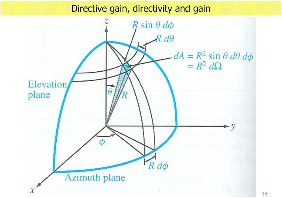
15 Directive gain, directivity and gain Directive gain G D (,φ) atio of the radiation intensity in a particular direction(,φ) to the average radiation intensity. U (, φ ) U (, φ ) G D (, φ ) U W / 4π avg Directivity Maximum value of the directive gain in a certain direction. D Max { (, φ )} G d Power Gain atio of the radiation intensity in a given direction to the radiation intensity of a lossless isotropic radiator that has the same input power. U (, φ ) G p (, φ ) W / 4π in rad 5
} G d Power Gain atio of the radiation intensity in a given direction to the radiation intensity of a")
16 Example Find the directive gain of a Hertzian dipole. P avg P avg e H ( E *) E H φ ( Idl ) 3 π r U P avg r η o ( Idl ) 3 π I sin η o sin H φ E 6
 3 π r U P avg r η o ( Idl ) 3 π I")
17 7 Example and then ( ) π φ φ φ π π 0 0 sin 3 4 / sin sin sin ), ( ), ( d d U U G avg D
, ( d d U U G avg")
18 Example 8
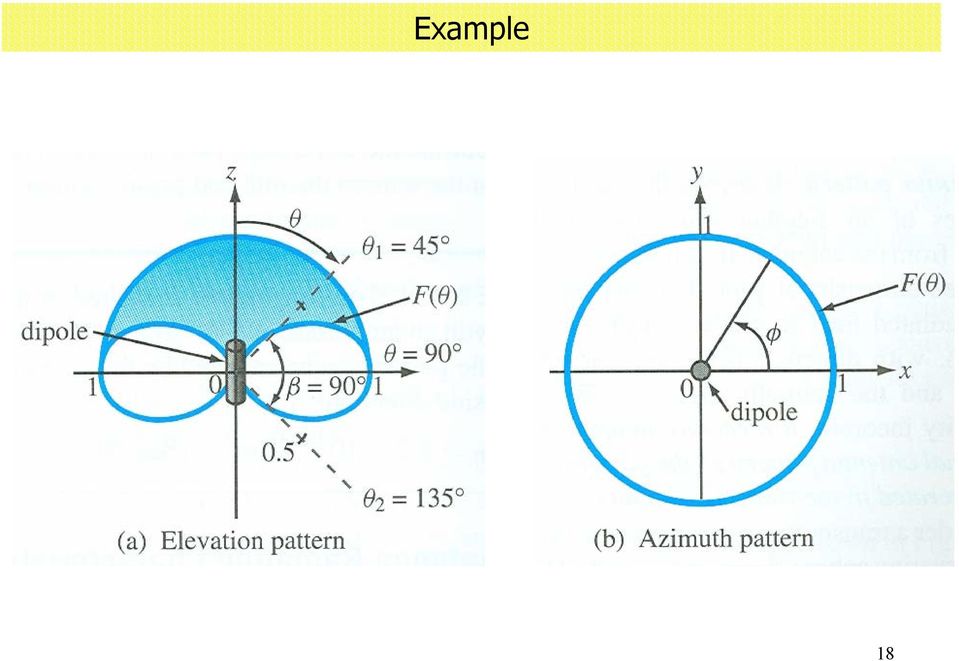
19 Example Directive gain and the directivity of the Hertzian dipole G D (, φ ) D G d 3 sin 3 ( π /, φ ).76 db I Suppose the radiation efficiency is 46%, G p 0.46 D db ( W rad / W in 0.46) 9

20 Example Find the radiation resistance of a Hertzian dipole P r π 0 0 π P ( dl ) avg I η o 3π I ( dl ) η o π I dl 80π λ dl 80π λ sin ddφ dl Suppose, Ω Poor radiator!! λ r 0 r π 0 0 π sin 3 ddφ 0

21 Linear dipole antenna Knowing the current distribution I(z), we can sum up the fields due to the infinitesimal segments on the antenna using the results of the Hertzian dipole. η ˆ j o I m e E π ˆ ji m e H φ π cos F ( ) jk jk F ( ) F ( ) a ( h cos ) φ sin cos h h I F() is called the pattern function
22 Linear dipole antenna Antenna pattern E-plane pattern (pattern function versus for a constant φ) H-plane pattern (pattern function versus φ for a constant π/)
23 Linear dipole antenna At certain dipole lengths ( λ/, λ ) called resonant lengths, the input impedance is purely resistive. For half-wavelength dipole, Z in r 73 Ω The pattern pattern for a half-wavelength dipole is cos ( h cos ) cos h F ( ) sin π cos cos sin D.64 3
24 Effective Area and Friis Equation Effective Area The effective area A e of a receiving antenna is the ratio of the time-average power received to the time-average power density of the incident wave at the antenna. A P / e L P avg It may be shown that is A e related to the directive gain as: A λ 4π e G D (, φ ) 4
25 Friis Equation Effective Area and Friis Equation Consider two antennae separated by a distance r. The transmitting antenna transmits a total power P t. A e, G D, P t A e, G D, P L r The time-average power density at the receiving antenna is P avg P t 4πr G D 5
26 6 Effective Area and Friis Equation The power received to the load is (Friis Equation) ( ) t D D avg D e avg L P G G r P G A P P 4 4 π λ π λ ( ) 4 D D t L G G r P P π λ
Antennas. Antennas are transducers that transfer electromagnetic energy between a transmission line and free space. Electromagnetic Wave
 Antennas Transmitter I Transmitting Antenna Transmission Line Electromagnetic Wave I Receiver I Receiving Antenna Transmission Line Electromagnetic Wave I Antennas are transducers that transfer electromagnetic
Fundamentals of Electromagnetic Fields and Waves: I
 Fundamentals of Electromagnetic Fields and Waves: I Fall 2007, EE 30348, Electrical Engineering, University of Notre Dame Mid Term II: Solutions Please show your steps clearly and sketch figures wherever
Laboratory #6: Dipole and Monopole Antenna Design
 EEE 171 Lab #6 1 Laboratory #6: Dipole and Monopole Antenna Design I. OBJECTIVES Design several lengths of dipole antennas. Design appropriate impedance matching networks for those antennas. The antennas
Antenna Properties and their impact on Wireless System Performance. Dr. Steven R. Best. Cushcraft Corporation 48 Perimeter Road Manchester, NH 03013
 Antenna Properties and their impact on Wireless System Performance Dr. Steven R. Best Cushcraft Corporation 48 Perimeter Road Manchester, NH 03013 Phone (603) 627-7877 FAX: (603) 627-1764 Email: [email protected]
Examples of Uniform EM Plane Waves
 Examples of Uniform EM Plane Waves Outline Reminder of Wave Equation Reminder of Relation Between E & H Energy Transported by EM Waves (Poynting Vector) Examples of Energy Transport by EM Waves 1 Coupling
6 J - vector electric current density (A/m2 )
") Determination of Antenna Radiation Fields Using Potential Functions Sources of Antenna Radiation Fields 6 J - vector electric current density (A/m2 ) M - vector magnetic current density (V/m 2 ) Some problems
Determination of Antenna Radiation Fields Using Potential Functions Sources of Antenna Radiation Fields 6 J - vector electric current density (A/m2 ) M - vector magnetic current density (V/m 2 ) Some problems
arxiv:1111.4354v2 [physics.acc-ph] 27 Oct 2014
![arxiv:1111.4354v2 [physics.acc-ph] 27 Oct 2014](/thumbs/39/19151390.jpg "arxiv:1111.4354v2 [physics.acc-ph] 27 Oct 2014") Theory of Electromagnetic Fields Andrzej Wolski University of Liverpool, and the Cockcroft Institute, UK arxiv:1111.4354v2 [physics.acc-ph] 27 Oct 2014 Abstract We discuss the theory of electromagnetic
Theory of Electromagnetic Fields Andrzej Wolski University of Liverpool, and the Cockcroft Institute, UK arxiv:1111.4354v2 [physics.acc-ph] 27 Oct 2014 Abstract We discuss the theory of electromagnetic
Two primary advantages of radars: all-weather and day /night imaging
 Lecture 0 Principles of active remote sensing: Radars. Objectives: 1. Radar basics. Main types of radars.. Basic antenna parameters. Required reading: G: 8.1, p.401-40 dditional/advanced reading: Online
An equivalent circuit of a loop antenna.
 3.2.1. Circuit Modeling: Loop Impedance A loop antenna can be represented by a lumped circuit when its dimension is small with respect to a wavelength. In this representation, the circuit parameters (generally
Amplification of the Radiation from Two Collocated Cellular System Antennas by the Ground Wave of an AM Broadcast Station
 Amplification of the Radiation from Two Collocated Cellular System Antennas by the Ground Wave of an AM Broadcast Station Dr. Bill P. Curry EMSciTek Consulting Co., W101 McCarron Road Glen Ellyn, IL 60137,
Antennas 101 The Basics. Ward Silver NØAX
 Antennas 101 The Basics Ward Silver NØAX The Basics - 1 Antennas radiate (or receive) because electrons are accelerated (or are caused to accelerate) in the antenna s elements Radio or electromagnetic
RADIATION PATTERNS. The half-power (-3 db) beamwidth is a measure of the directivity of the antenna.
 beamwidth is a measure of the directivity of the antenna.") RADIATION PATTERNS The radiation pattern is a graphical depiction of the relative field strength transmitted from or received by the antenna. Antenna radiation patterns are taken at one frequency, one
RADIATION PATTERNS The radiation pattern is a graphical depiction of the relative field strength transmitted from or received by the antenna. Antenna radiation patterns are taken at one frequency, one
Basic Wire Antennas. Part II: Loops and Verticals
 Basic Wire Antennas Part II: Loops and Verticals A loop antenna is composed of a single loop of wire, greater than a half wavelength long. The loop does not have to be any particular shape. RF power can
UNIVERSITETET I OSLO
 UNIVERSITETET I OSLO Det matematisk-naturvitenskapelige fakultet Exam in: FYS 310 Classical Mechanics and Electrodynamics Day of exam: Tuesday June 4, 013 Exam hours: 4 hours, beginning at 14:30 This examination
AN 1629 UHF RFID Label Antenna Design
 UHF RFID Label Antenna Design UHF Antenna Design Rev. 1.0 05.09.2008 Application note Document information Info Keywords Abstract Content UHF, label antenna design, UCODE This document provides a general
Chapter 1 ANTENNA FUNDAMENTALS. Paul Wade W1GHZ (ex-n1bwt) 1994,1997,1998 ANTENNA BASICS
 1994,1997,1998 ANTENNA BASICS") Chapter 1 ANTENNA FUNDAMENTALS Paul Wade W1GHZ (ex-n1bwt) 1994,1997,1998 Introduction Antenna gain is essential for microwave communication since it helps both transmitting and receiving, it is doubly
Chapter 1 ANTENNA FUNDAMENTALS Paul Wade W1GHZ (ex-n1bwt) 1994,1997,1998 Introduction Antenna gain is essential for microwave communication since it helps both transmitting and receiving, it is doubly
Chapter 12 Driven RLC Circuits
 hapter Driven ircuits. A Sources... -. A ircuits with a Source and One ircuit Element... -3.. Purely esistive oad... -3.. Purely Inductive oad... -6..3 Purely apacitive oad... -8.3 The Series ircuit...
Physics 6C, Summer 2006 Homework 2 Solutions
 Physics 6C, Summer 006 Homework Solutions All problems are from the nd edition of Walker. Numerical values are different for each student. Chapter 3 Problems. Figure 3-30 below shows a circuit containing
THE FLORIDA STATE UNIVERSITY COLLEGE OF ENGINEERING DESIGN OF A COMPACT MICROSTRIP PATCH ANTENNA FOR USE IN WIRELESS/CELLULAR DEVICES.
 THE FLORIDA STATE UNIVERSITY COLLEGE OF ENGINEERING DESIGN OF A COMPACT MICROSTRIP PATCH ANTENNA FOR USE IN WIRELESS/CELLULAR DEVICES By: Punit S. Nakar A Thesis submitted to the Department of Electrical
1 Numerical Electromagnetics Code (NEC)
") Wire Antenna Modelling with NEC-2 1 Numerical Electromagnetics Code (NEC) The software Numerical Electromagnetics Code (NEC-2) has been developed in the 1970s in the Lawrence Livermore Laboratory in Livermore,
Wire Antenna Modelling with NEC-2 1 Numerical Electromagnetics Code (NEC) The software Numerical Electromagnetics Code (NEC-2) has been developed in the 1970s in the Lawrence Livermore Laboratory in Livermore,
ABHELSINKI UNIVERSITY OF TECHNOLOGY
 Basic of Propagation Theory S-72.333 Physical Layer Methods in Wireless Communication Systems Fabio Belloni Helsinki University of Technology Signal Processing Laboratory [email protected] 23 November
Chapter 33. The Magnetic Field
 Chapter 33. The Magnetic Field Digital information is stored on a hard disk as microscopic patches of magnetism. Just what is magnetism? How are magnetic fields created? What are their properties? These
Review Paper for Broadband CPW-Fed T-Shape Slot Antenna
 Review Paper for Broadband CPW-Fed T-Shape Slot Antenna Shahpure Sana 1, Bharate Rajashri 2, Prof. Jadhav D.A. 3 1,2 BE, Dept. of E&TC, Brahmdevdada Mane Institute of Technology, Dist. Solapur (Maharashtra)
Transmission Lines. Smith Chart
 Smith Chart The Smith chart is one of the most useful graphical tools for high frequency circuit applications. The chart provides a clever way to visualize complex functions and it continues to endure
Basic Antenna Theory and Application
 Project Number: SNM MQP 0414 Basic Antenna Theory and Application A Major Qualifying Project Report: Submitted to the Faculty of the WORCESTER POLYTECHNIC INSTITUTE in partial fulfillment of the requirements
Voltage Across the Terminals of a Receiving Antenna
 Voltage Across the Terminals of a Receiving Antenna 1 Problem Kirk T. McDonald Joseph Henry Laboratories, Princeton University, Princeton, NJ 08544 (June 25, 2007; updated June 27, 2013) Deduce the no-load
$1 SRD Antennas. Keywords. Introduction. Overview. By P. M. Evjen. PCB antenna design Body-worn and handheld antennas. Antenna theory Small antennas
 $1 SRD Antennas By P. M. Evjen Keywords Antenna theory Small antennas PCB antenna design Body-worn and handheld antennas Introduction This application note addresses one of the most important issues faced
Fundamentals of radio communication
 Fundamentals of radio communication This worksheet and all related files are licensed under the Creative Commons Attribution License, version 1.0. To view a copy of this license, visit http://creativecommons.org/licenses/by/1.0/,
Impedance Matching and Matching Networks. Valentin Todorow, December, 2009
 Impedance Matching and Matching Networks Valentin Todorow, December, 2009 RF for Plasma Processing - Definition of RF What is RF? The IEEE Standard Dictionary of Electrical and Electronics Terms defines
Radiated Emission and Susceptibility
 Radiated Emission and Susceptibility Tzong-Lin Wu, Ph.D. EMC Lab Department of Electrical Engineering National Taiwan University Differential-Mode v.s. Common-mode Currents 1 Differential-Mode v.s. Common-mode
Antenna Basic Concepts
 ANTENNA An antenna is a device to transmit and/or receive electromagnetic waves. Electromagnetic waves are often referred to as radio waves. Most antennas are resonant devices, which operate efficiently
Antenna Glossary Before we talk about specific antennas, there are a few common terms that must be defined and explained:
 Antenna Basics Introduction Antennas are a very important component of communication systems. By definition, an antenna is a device used to transform an RF signal, traveling on a conductor, into an electromagnetic
45. The peak value of an alternating current in a 1500-W device is 5.4 A. What is the rms voltage across?
 PHYS Practice Problems hapters 8- hapter 8. 45. The peak value of an alternating current in a 5-W device is 5.4 A. What is the rms voltage across? The power and current can be used to find the peak voltage,
Human Exposure Limits
 Human Exposure Limits Session 3 0 Version December 2014 Learning objectives In this session we will: Learn about the international exposure limits for workers and the public Learn about methods for assessing
Alternating-Current Circuits
 hapter 1 Alternating-urrent ircuits 1.1 A Sources... 1-1. Simple A circuits... 1-3 1..1 Purely esistive load... 1-3 1.. Purely Inductive oad... 1-5 1..3 Purely apacitive oad... 1-7 1.3 The Series ircuit...
Chapter 27 Magnetic Field and Magnetic Forces
 Chapter 27 Magnetic Field and Magnetic Forces - Magnetism - Magnetic Field - Magnetic Field Lines and Magnetic Flux - Motion of Charged Particles in a Magnetic Field - Applications of Motion of Charged
Chapter 22: Electric Flux and Gauss s Law
 22.1 ntroduction We have seen in chapter 21 that determining the electric field of a continuous charge distribution can become very complicated for some charge distributions. t would be desirable if we
40m-10m DELTA LOOP ANTENNA - GU3WHN
 This simple broad band antenna is easy to build, has gain similar to that of a dipole and is tolerant of nearby objects. It can be erected in almost any configuration provided the wires are well separated
1. Basics of LASER Physics
 1. Basics of LASER Physics Dr. Sebastian Domsch (Dipl.-Phys.) Computer Assisted Clinical Medicine Medical Faculty Mannheim Heidelberg University Theodor-Kutzer-Ufer 1-3 D-68167 Mannheim, Germany [email protected]
CHAPTER 4. Electromagnetic Spectrum
 ELEC4504 Avionics Systems 9 CHAPTER 4. Electromagnetic Spectrum 4.1. Electromagnetic (EM) Waves In free space (or the atmosphere) the electric field is perpendicular to the magnetic field and both are
Part I: Wireless System Characteristics
 Part I: Wireless System Characteristics Smart grid technology holds great promise of cleaner air, more efficient power, and lower greenhouse gas emissions. In a smart grid system, the system itself will
Design & Simulation of 8-Shape Slotted Microstrip Patch Antenna
 World Applied Sciences Journal 31 (6): 1065-1071, 2014 ISSN 1818-4952 IDOSI Publications, 2014 DOI: 10.5829/idosi.wasj.2014.31.06.1462 Design & Simulation of 8-Shape Slotted Microstrip Patch Antenna Sohag
Selecting Receiving Antennas for Radio Tracking
 Selecting Receiving Antennas for Radio Tracking Larry B Kuechle, Advanced Telemetry Systems, Inc. Isanti, Minnesota 55040 [email protected] The receiving antenna is an integral part of any radio location
potential in the centre of the sphere with respect to infinity.
 Umeå Universitet, Fysik 1 Vitaly Bychkov Prov i fysik, Electricity and Waves, 2006-09-27, kl 16.00-22.00 Hjälpmedel: Students can use any book. Define the notations you are using properly. Present your
Tesla Wireless Energy Transfer at CCC
 Tesla Wireless Energy Transfer at CCC Davor Jadrijević December 10, 2009 Abstract Tesla s Long Distance High-Power and High-Efficiency Wireless Energy Transfer System is still a mystery to our technology.
EE4367 Telecom. Switching & Transmission. Prof. Murat Torlak
 Path Loss Radio Wave Propagation The wireless radio channel puts fundamental limitations to the performance of wireless communications systems Radio channels are extremely random, and are not easily analyzed
104 Practice Exam 2-3/21/02
 104 Practice Exam 2-3/21/02 1. Two electrons are located in a region of space where the magnetic field is zero. Electron A is at rest; and electron B is moving westward with a constant velocity. A non-zero
Problem Solving 5: Magnetic Force, Torque, and Magnetic Moments
 MASSACHUSETTS INSTITUTE OF TECHNOLOY Department of Physics Problem Solving 5: Magnetic Force, Torque, and Magnetic Moments OBJECTIVES 1. To start with the magnetic force on a moving charge q and derive
Minimum requirements for DVB-T receiving antennas for portable indoor and portable outdoor reception
 Deutsche TV Platform Minimum requirements for DVB-T receiving antennas for portable indoor and portable outdoor reception compiled by Working Group: DVB-T launch (a working group of the Deutsche TV Platform)
CONCEPT-II. Overview of demo examples
 CONCEPT-II CONCEPT-II is a frequency domain method of moment (MoM) code, under development at the Institute of Electromagnetic Theory at the Technische Universität Hamburg-Harburg (www.tet.tuhh.de). Overview
Applications in EMC testing. Outline. Antennas for EMC Testing. Terminology
 Antennas for EMC Testing Zhong Chen ETS-Lindgren 1301 Arrow Point Drive Cedar Park, TX 78613 [email protected] Outline EMC Terms and Definitions Typical EMC Antennas Calibration of EMC Antennas
Polarization of Light
 Polarization of Light References Halliday/Resnick/Walker Fundamentals of Physics, Chapter 33, 7 th ed. Wiley 005 PASCO EX997A and EX999 guide sheets (written by Ann Hanks) weight Exercises and weights
A METHOD OF CALIBRATING HELMHOLTZ COILS FOR THE MEASUREMENT OF PERMANENT MAGNETS
 A METHOD OF CALIBRATING HELMHOLTZ COILS FOR THE MEASUREMENT OF PERMANENT MAGNETS Joseph J. Stupak Jr, Oersted Technology Tualatin, Oregon (reprinted from IMCSD 24th Annual Proceedings 1995) ABSTRACT The
GPR Polarization Simulation with 3D HO FDTD
 Progress In Electromagnetics Research Symposium Proceedings, Xi an, China, March 6, 00 999 GPR Polarization Simulation with 3D HO FDTD Jing Li, Zhao-Fa Zeng,, Ling Huang, and Fengshan Liu College of Geoexploration
Understanding SWR by Example
 Understanding SWR by Example Take the mystery and mystique out of standing wave ratio. Darrin Walraven, K5DVW It sometimes seems that one of the most mysterious creatures in the world of Amateur Radio
Electromagnetism Laws and Equations
 Electromagnetism Laws and Equations Andrew McHutchon Michaelmas 203 Contents Electrostatics. Electric E- and D-fields............................................. Electrostatic Force............................................2
Pre-Compliance Test Method for Radiated Emissions of Automotive Components Using Scattering Parameter Transfer Functions
 PreCompliance Test Method for Radiated Emissions of Automotive Components Using Scattering Parameter Transfer Functions D. Schneider 1*, S. Tenbohlen 1, W. Köhler 1 1 Institute of Power Transmission and
Coupling Effect in Substation Ground Measurements
 SERBIAN JOURNAL OF ELECTRICAL ENGINEERING Vol. 9, No. 3, October 2012, 315-324 UDK: 621.316.13.011.2 DOI: 10.2298/SJEE1203315F Coupling Effect in Substation Ground Measurements Alex Farber 1, Boris Katz
Experiment 7: Familiarization with the Network Analyzer
 Experiment 7: Familiarization with the Network Analyzer Measurements to characterize networks at high frequencies (RF and microwave frequencies) are usually done in terms of scattering parameters (S parameters).
You will need the following pieces of equipment to complete this experiment:
 UNIVERSITY OF TORONTO FACULTY OF APPLIED SCIENCE AND ENGINEERING The Edward S. Rogers Sr. Department of Electrical and Computer Engineering ECE422H1S: RADIO AND MICROWAVE WIRELESS SYSTEMS EXPERIMENT 3:
Examples of magnetic field calculations and applications. 1 Example of a magnetic moment calculation
 Examples of magnetic field calculations and applications Lecture 12 1 Example of a magnetic moment calculation We consider the vector potential and magnetic field due to the magnetic moment created by
This Antenna Basics reference guide includes basic information about antenna types, how antennas work, gain, and some installation examples.
 Antenna Basics This Antenna Basics reference guide includes basic information about antenna types, how antennas work, gain, and some installation examples. What Do Antennas Do? Antennas transmit radio
F en = mω 0 2 x. We should regard this as a model of the response of an atom, rather than a classical model of the atom itself.
 The Electron Oscillator/Lorentz Atom Consider a simple model of a classical atom, in which the electron is harmonically bound to the nucleus n x e F en = mω 0 2 x origin resonance frequency Note: We should
Broadband Slotted Coaxial Broadcast Antenna Technology
 Broadband Slotted Coaxial Broadcast Antenna Technology Summary Slotted coaxial antennas have many advantages over traditional broadband panel antennas including much smaller size and wind load, higher
2/20/2009 3 Transmission Lines and Waveguides.doc 1/3. and Waveguides. Transmission Line A two conductor structure that can support a TEM wave.
 2/20/2009 3 Transmission Lines and Waveguides.doc 1/3 Chapter 3 Transmission Lines and Waveguides First, some definitions: Transmission Line A two conductor structure that can support a TEM wave. Waveguide
G019.A (4/99) UNDERSTANDING COMMON MODE NOISE
 UNDERSTANDING COMMON MODE NOISE") UNDERSTANDING COMMON MODE NOISE PAGE 2 OF 7 TABLE OF CONTENTS 1 INTRODUCTION 2 DIFFERENTIAL MODE AND COMMON MODE SIGNALS 2.1 Differential Mode signals 2.2 Common Mode signals 3 DIFFERENTIAL AND COMMON
UNDERSTANDING COMMON MODE NOISE PAGE 2 OF 7 TABLE OF CONTENTS 1 INTRODUCTION 2 DIFFERENTIAL MODE AND COMMON MODE SIGNALS 2.1 Differential Mode signals 2.2 Common Mode signals 3 DIFFERENTIAL AND COMMON
Electromagnetism - Lecture 2. Electric Fields
 Electromagnetism - Lecture 2 Electric Fields Review of Vector Calculus Differential form of Gauss s Law Poisson s and Laplace s Equations Solutions of Poisson s Equation Methods of Calculating Electric
The performance improvement by ferrite loading means - increasing, - increasing of ratio, implicitly related to the input impedance.
 3.2.3. Ferrite Loading Magnetic ferrite loading can enhance a transmitting signal as high as 2 to 10 db for MHz [Devore and Bohley, 1977]. There is an optimum frequency range where ferrite loading is beneficial.
Design and Electromagnetic Modeling of E-Plane Sectoral Horn Antenna For Ultra Wide Band Applications On WR-137 & WR- 62 Waveguides
 International Journal of Engineering Science Invention ISSN (Online): 2319 6734, ISSN (Print): 2319 6726 Volume 3 Issue 7ǁ July 2014 ǁ PP.11-17 Design and Electromagnetic Modeling of E-Plane Sectoral Horn
Structure Factors 59-553 78
 78 Structure Factors Until now, we have only typically considered reflections arising from planes in a hypothetical lattice containing one atom in the asymmetric unit. In practice we will generally deal
Tuning a Monopole Antenna Using a Network Analyzer
 11/21/11 Tuning a Monopole Antenna Using a Network Analyzer Chris Leonard Executive Summary: When designing a monopole antenna it is important to know at which frequency the antenna will be operating at.
Consideration of a high-capacity foil cable:
 Consideration of a high-capacity foil cable: Newly discovered ancient knowledge. The old RF-developers already knew the benefits of longplanar lines and have been used (electronic) Eonen (times) thin flat
Gauss Formulation of the gravitational forces
 Chapter 1 Gauss Formulation of the gravitational forces 1.1 ome theoretical background We have seen in class the Newton s formulation of the gravitational law. Often it is interesting to describe a conservative
DIMENSIONING OF CURRENT TRANSFORMERS FOR PROTECTON APPLICATION
 ÿþ üûúùø öõöôùóùõò CT Dimensioning DIMENSIONING OF CURRENT TRANSFORMERS FOR PROTECTON APPLICATION Application note GER3973 1 CT Dimensioning ÿþ üûúùø öõöôùóùõò GER-3973 Application note ÿþ üûúùø öõöôùóùõò
PROJECT REPORT ANTENNA DESIGN, SIMULATION AND FABRICATION
 PROJECT REPORT ON ANTENNA DESIGN, SIMULATION AND FABRICATION This project report is submitted to VNIT in partial fulfillment of the requirements for the degree of Bachelor of Technology in Electronics
Guidelines on the assessment of installations against electromagnetic radiation (EMR) exposure limits
 exposure limits") Guidelines on the assessment of installations against electromagnetic radiation (EMR) exposure limits (Edition eptember 000) Disclaimer Unless otherwise specified, the information contained in these guidelines
Guidelines on the assessment of installations against electromagnetic radiation (EMR) exposure limits (Edition eptember 000) Disclaimer Unless otherwise specified, the information contained in these guidelines
EMC STANDARDS STANDARDS AND STANDARD MAKING BODIES. International. International Electrotechnical Commission (IEC) http://www.iec.
 http://www.iec.") EMC STANDARDS The EMC standards that a particular electronic product must meet depend on the product application (commercial or military) and the country in which the product is to be used. These EMC regulatory
EMC STANDARDS The EMC standards that a particular electronic product must meet depend on the product application (commercial or military) and the country in which the product is to be used. These EMC regulatory
Lecture L5 - Other Coordinate Systems
 S. Widnall, J. Peraire 16.07 Dynamics Fall 008 Version.0 Lecture L5 - Other Coordinate Systems In this lecture, we will look at some other common systems of coordinates. We will present polar coordinates
Avaya WLAN 9100 External Antennas for use with the WAO-9122 Access Point
 Avaya WLAN 9100 External Antennas for use with the WAO-9122 Access Point Overview To optimize the overall performance of a WLAN in an outdoor deployment it is important to understand how to maximize coverage
9 Multiplication of Vectors: The Scalar or Dot Product
 Arkansas Tech University MATH 934: Calculus III Dr. Marcel B Finan 9 Multiplication of Vectors: The Scalar or Dot Product Up to this point we have defined what vectors are and discussed basic notation
Fraunhofer Diffraction
 Physics 334 Spring 1 Purpose Fraunhofer Diffraction The experiment will test the theory of Fraunhofer diffraction at a single slit by comparing a careful measurement of the angular dependence of intensity
RLC Resonant Circuits
 C esonant Circuits Andrew McHutchon April 20, 203 Capacitors and Inductors There is a lot of inconsistency when it comes to dealing with reactances of complex components. The format followed in this document
MITSUBISHI ELECTRIC ANNOUNCES THE SUCCESSFUL DEVELOPMENT OF AN AIRBORNE Ku-BAND ANTENNA SUBSYSTEM FOR SATELLITE COMMUNICATIONS
 FOR IMMEDIATE RELEASE No. 2330 Product Inquiries: Media Contact: Yutaka Kamada Oliver Cox Mitsubishi Electric Corporation Mitsubishi Electric Corporation Tel: +81-3-3218-2391 Tel: +81-3-3218-2346 [email protected]
Understanding Poles and Zeros
 MASSACHUSETTS INSTITUTE OF TECHNOLOGY DEPARTMENT OF MECHANICAL ENGINEERING 2.14 Analysis and Design of Feedback Control Systems Understanding Poles and Zeros 1 System Poles and Zeros The transfer function
Design of Rectangular Microstrip Slot Antenna for Multi Band Application
 Design of Rectangular Microstrip Slot Antenna for Multi Band Application K.Thamarairubini 1, V. Kiruthiga 2 Assistant professor, Dept. of ECE, BIT College, Sathyamangalam, Tamilnadu, India 1 PG Student
Human Exposure to Outdoor PLC System
 1602 PIERS Proceedings, Marrakesh, MOROCCO, March 20 23, 2011 Human Exposure to Outdoor PLC System Vicko Doric 1, Dragan Poljak 1, and Khalil El Khamlichi Drissi 2 1 University of Split, Croatia 2 Blaise
Antenna Trainer EAN. www.edibon.com. Technical Teaching Equipment INTRODUCTION
 Antenna Trainer EAN Technical Teaching Equipment Products Products range Units 3.-Communications INTRODUCTION Antennas are the main element of aerial communications. They are the transition between a transmission
Flexible PCB Antenna with Cable Integration Application Note Version 2
 Flexible PCB Antenna with Cable Integration Application Note Version 2 CONTENTS 1. BASICS 2. APPLICATIONS 3. SIZE 4. SHAPE 5. GROUND PLANE SIZE 6. IMPEDANCE 7. BANDWIDTH 8. VSWR 9. GAIN 10. EFFICIENCY
RF EXPOSURE LIMITS AND TESTING REQUIREMENTS
 RF EXPOSURE LIMITS AND TESTING REQUIREMENTS Jay Moulton Vice President March 12, 2013 1 OVERVIEW Specific Absorption Rate (SAR) and Maximum Permissible Exposure (MPE) Standards and Limits Evaluation Methods
Magnetic Dipoles. Magnetic Field of Current Loop. B r. PHY2061 Enriched Physics 2 Lecture Notes
 Disclaimer: These lecture notes are not meant to replace the course textbook. The content may be incomplete. Some topics may be unclear. These notes are only meant to be a study aid and a supplement to
Electrical Resonance
 Electrical Resonance (R-L-C series circuit) APPARATUS 1. R-L-C Circuit board 2. Signal generator 3. Oscilloscope Tektronix TDS1002 with two sets of leads (see Introduction to the Oscilloscope ) INTRODUCTION
DEGREE: Bachelor's Degree in Industrial Electronics and Automation COURSE: 1º TERM: 2º WEEKLY PLANNING
 SESSION WEEK COURSE: Physics II DEGREE: Bachelor's Degree in Industrial Electronics and Automation COURSE: 1º TERM: 2º WEEKLY PLANNING DESCRIPTION GROUPS (mark ) Indicate YES/NO If the session needs 2
Designing Log Periodic Antennas
 Designing Log Periodic Antennas By Glen Dash, Ampyx LLC, GlenDash at alum.mit.edu Copyright 2000, 2005 Ampyx LLC Lightweight and precise, the log periodic has become a favorite among EMC engineers. In
Analysis of Electromagnetic Propulsion on a Two-Electric-Dipole System
 Electronics and Communications in Japan, Part 2, Vol. 83, No. 4, 2000 Translated from Denshi Joho Tsushin Gakkai Ronbunshi, Vol. J82-C-I, No. 6, June 1999, pp. 310 317 Analysis of Electromagnetic Propulsion
PHYS 222 Spring 2012 Final Exam. Closed books, notes, etc. No electronic device except a calculator.
 PHYS 222 Spring 2012 Final Exam Closed books, notes, etc. No electronic device except a calculator. NAME: (all questions with equal weight) 1. If the distance between two point charges is tripled, the
Co-simulation of Microwave Networks. Sanghoon Shin, Ph.D. RS Microwave
 Co-simulation of Microwave Networks Sanghoon Shin, Ph.D. RS Microwave Outline Brief review of EM solvers 2D and 3D EM simulators Technical Tips for EM solvers Co-simulated Examples of RF filters and Diplexer
Chapter 11. Inductors ISU EE. C.Y. Lee
 Chapter 11 Inductors Objectives Describe the basic structure and characteristics of an inductor Discuss various types of inductors Analyze series inductors Analyze parallel inductors Analyze inductive