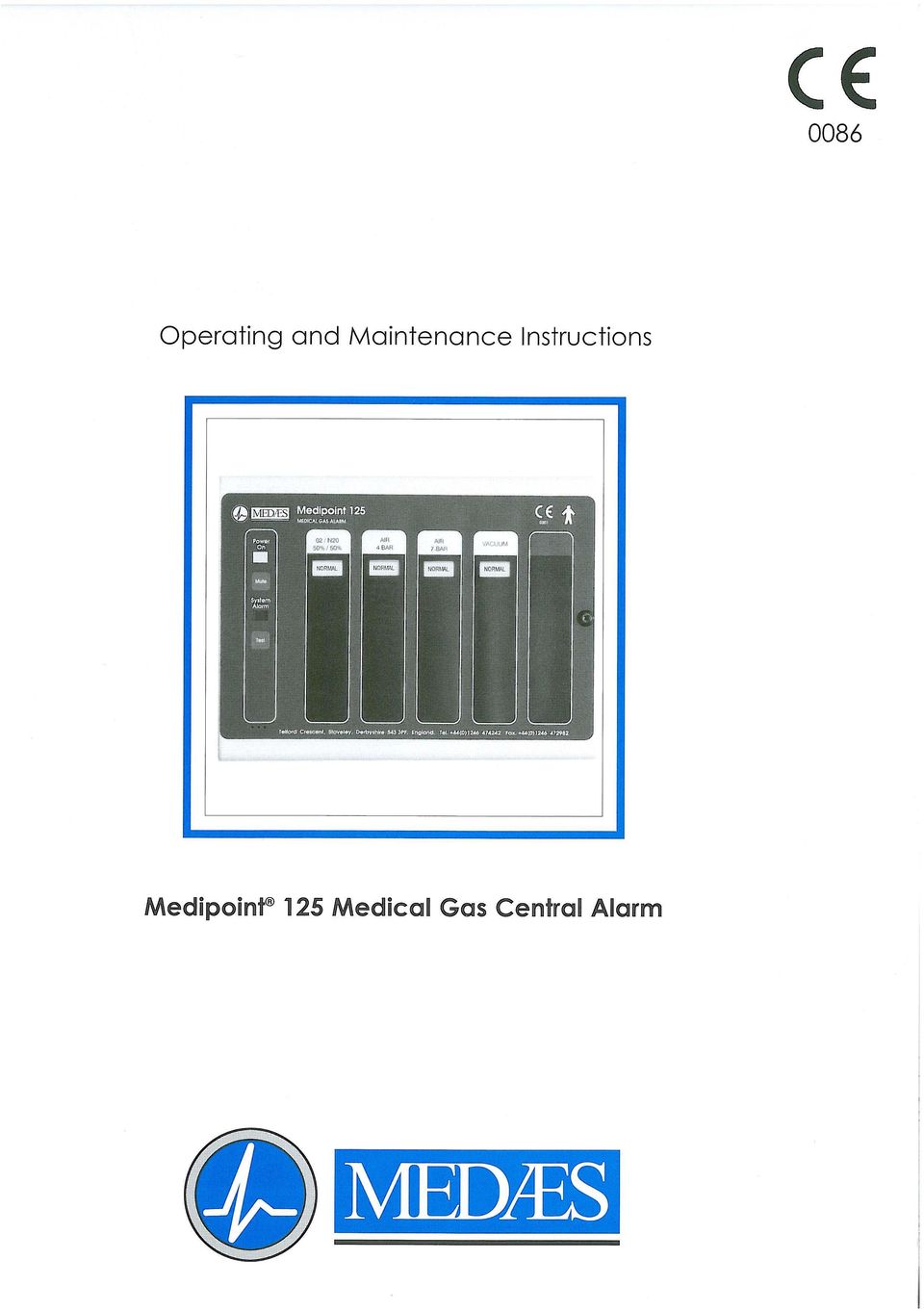
Operating and Maintenance Instructions MEDIPOINT 125 MEDICAL GAS CENTRAL ALARM
|
|
|
- Nathaniel Wilkerson
- 9 years ago
- Views:
Transcription
1
2 Operating and Maintenance Instructions MEDIPOINT 125 MEDICAL GAS CENTRAL ALARM CONTENTS SECTION 0. SAFETY, STORAGE AND HANDLING DATA 0.1 Indentification of symbols 0.2 Environmental conditions 0.3 Environmental protection 0.4 Electromagnetic interference 0.5 Cleaning of panels 0.6 Electrical details 1. DESCRIPTION AND OPERATION 1.1 Introduction 1.2 Standards 1.3 Alarm panels 1.4 Visual displays 1.5 TEST and MUTE switches 1.6 Audible warnings 1.7 Printed circuit boards Light display printed circuit board Power supply printed circuit board Standby battery 1.8 Alarm contact line fault 1.9 Remote audible warning devices 1.10 Medipoint 125 Relay interface panel 1.11 Operation of the alarm system 1.12 Programming of the alarm system 2. COMMISSIONING 2.1 Introduction 2.2 Functional tests 2.3 Alarm panel. Check internal connections 2.4 Electrical power supply. Switch ON. 2.5 Alarm Panel. Test 2.6 Gas service. Check alarm conditions 2.7 Audible warning. Check 2.8 Remote audible. Check 2.9 Relay interface panel. Check 2.10 SYSTEM ALARM indication. Check 2.11 Central alarm panel(s). Check MUTE operation Alarm system. Set. 3. OPERATING INSTRUCTIONS 3.1 General Operation 3.2 SYSTEM ALARM light 3.3 TEST switch operation 3.4 MUTE switch operation 4. MAINTENANCE 4.1 Introduction 4.2 Tools and equipment 4.3 Customer recommended maintenance 4.4 Weekly inspection 4.5 Quarterly inspection 4.6 Annual inspection 4.7 LED indicator replacement 4.8 Replacing the light display printed circuit board 4.9 Replacing a power supply printed circuit board 4.10 Replacing a back up battery 5. FAULT DIAGNOSIS 5.1 Introduction 6. RECOMMENDED SPARES 6.1 Spares scheduling

3 Table 1. Medipoint 125 dimensions 2. Medipoint 125 alarm logic input panel to repeater panel 3. Medipoint 125 alarm logic repeater to repeater panel 4. Medipoint 125 programming 5. Medipoint 125 Relay interface programming 6. Test or mute switch fails to operate 7. Single LED indicator fails to illuminate 8. Alarm Panel loses all displays except system alarm 9. System alarm/fault indication with a serviceable gas 10. Remote alarm/recording system not operating correctly 11. Gas service indicates normal with a Gas Service failure condition 12. System alarm and audible fail to operate on power failure 13. A gas service display flashing (including normal) with System Alarm 14. Minimum recommended spares scheduling per annum Figure 1. Light display switch positions 2. Relay panel switch positions
 with System Alarm 14. Minimum recommended spares scheduling per annum Figure 1.")
4 0. SAFETY, STORAGE AND HANDLING DATA This section gives safety, storage, and handling information for Hill-Rom MEDÆS Ltd. Medipoint 125 medical gas central alarm. Circuit diagrams, component parts lists and descriptions are available on request. 0.1 Identification of symbols The following standard symbols apply to this product. The meanings of these symbols are as specified below: - - Read instructions - Temperature range - Date of manufacture (Year/Month) - 3 phase alternating current with neutral conductor - Protected earth connection - Type B applied part (as per BSEN : 1990) - Dangerous voltage 0.2 Environmental Transport and Storage Conditions Minimum ambient temperature - 0 degrees Celsius Maximum ambient temperature - 40 degrees Celsius Minimum relative humidity (non-condensing) - 10% Maximum relative humidity (non-condensing) - 95% Environmental Operating Conditions Minimum ambient temperature - 0 degrees Celsius Maximum ambient temperature - 40 degrees Celsius Minimum relative humidity (non-condensing) - 10% Maximum relative humidity (non-condensing) - 95% Atmospheric pressure range hpa 0.3 Environmental Protection Discard the unit and/or components in any standard refuse facility. The unit does not contain any hazardous substances. 0.4 Electromagnetic Interference The panel has been tested to BSEN : 1993 Medical electrical equipment - electromagnetic compatibility - requirements and tests. Ensure all input and data cables are physically separated from other mains and data cables.
 - Dangerous voltage 0.")
5 0. SAFETY, STORAGE AND HANDLING DATA continued 0.5 Cleaning The panel should be wiped over frequently with a damp cloth to remove any dust or foreign substances. 0.6 Electrical Details WARNING... IT IS NECESSARY TO CHECK THE INTEGRITY OF THE POWER SOURCE FOR SAFETY AT REGULAR INTERVALS. THESE CHECKS SHOULD BE CARRIED OUT ANNUALLY AND REPLACEMENT POWER SUPPLIES USED AS NECESSARY. Power source Mains operated using 110 or 230V, 50/60Hz, alternating current. The label adjacent to the mains connection shows whether the voltage is 110 or 230V. Current requirements 3.0 amps Type of protection against electric shock Class 1 (Mains supplied equipment using a protected earth) Mode of operation Continuous (equipment may be left switched on indefinitely) Degree of protection against ingress of liquids IPX0 (Not protected) Degree of mobility Permanently installed (This unit is electrically connected by permanent means) Degree of protection Type B (no Applied Part or with an Applied Part not designed to meet F type (floating) requirements) Degree of protection against flammable anaesthetic mixtures Not protected (not suitable for use with flammable gases) Rechargeable battery The rechargeable battery (ref. no ) should be replaced every 5 years.
 Mode of operation Continuous (equipment may be left switched on indefinitely) Degree of")
6 1. DESCRIPTION AND OPERATION 1.1 Introduction The Hill-Rom MEDÆS Medipoint 125 medical gas central alarm system is designed to provide full monitoring of a complete medical gas installation throughout a hospital. Medipoint 125 medical gas central alarm systems consist of a central panel, which normally displays all monitored gas services with repeater panels in locations as specified by the customer. Inputs from the respective medical gas supply systems enter the alarm system at the nearest alarm panel, thereby reducing the installation costs. Information is transmitted for display throughout the system by means of an advanced data transmission circuit. Medipoint 125 medical gas central alarm systems provide a totally flexible alarm system which may be adapted to fully satisfy the requirements of any application. Programming is performed by switches within the panel and a system is normally programmed during build, however panels are easily programmed and systems can easily be modified or extended on site. An individual Medipoint 125 alarm panel displays up to 5 gas services in a normal and 4 stage alarm conditions, or may be used to display a maximum of 20 traditional individual point alarms. Mounting multiple Medipoint 125 alarm panels in adjacent positions enables the Medipoint 125 central alarm system to monitor and display the required number of gas services. Facilities are incorporated to provide any combination of gas service or point alarm displays. One Medipoint 125 alarm panel is designated the master panel for control purposes. Any number of panels may be programmed as a central panel and cause all flashing displays on the system to change to steady when the MUTE switch on the central panel is operated. Each Medipoint 125 alarm panel connects directly with the mains electrical power supply and alarm panels are available for use with supplies of either 100V to 127V a.c. or 200V to 240V a.c. 50/60 Hz. Electrical power supplies should be from an essential circuit and fused at 3 Amps. Each Medipoint 125 alarm panel incorporates flashing alarm displays, a POWER ON indication, a SYSTEM ALARM indication, MUTE and TEST switches and an audible warning programmed to operate depending upon the alarm condition displayed. Alarm panels are interconnected by data transmission cable. Relay interface units input conditions into existing alarm systems or building management systems are available. 1.2 Standards The Hill-Rom MEDÆS Medipoint 125 medical gas central alarm system is specifically designed and manufactured to fully satisfy the National Health Service Model Engineering Specification C11, and is therefore ideal for HTM2022 applications. Hill-Rom MEDÆS Medipoint 125 medical gas alarms are suitable for both United Kingdom and International markets, and are fully tested prior to dispatch and packaged to provide maximum protection during transit. Alarm panel printed circuit boards are designed to operate in an ambient temperature of between 0c and +50c. Component assemblies must be stored in their packaging in dry conditions and storage temperatures must be between 0 o C and +50 o C. Alarm panel enclosures provide protection to IP32 (BS5490) and are electrically bonded to earth to provide safe installation. 1.3 Alarm Panels Each alarm panel consists of a first and second fix assembly, and are suitable for use with either surface or concealed installations. A bezel plate is provided for use with concealed installations and is fitted to the first fix assembly to give a neat appearance by covering the plaster joint. The front cover of the enclosure is hinged and retained by a special fastener which prevents unauthorised access. The assembly contains two printed circuit boards and provides a gas service display through windows in the front cover. The front cover has a flush dark finish polyester fascia to highlight the displays. Five columns of display windows indicate Normal and 4 alarm conditions, for each gas service monitored. Displays are illuminated by coloured LED block indicators and have captions to indicate the gas service, Normal and Alarm conditions. The alarm panel also incorporates a green LED to indicate that the electrical power supply is ON, and a red LED to indicate an alarm system fault (SYSTEM ALARM). A MUTE switch is provided to mute the audible warning and a TEST switch is provided to test the internal circuits, LED s and audible warning within the panel. Overall dimensions are detailed at Table 1.

7 1. DESCRIPTION AND OPERATION 1.3 Alarm Panels continued TABLE 1 : MEDIPOINT 125 DIMENSIONS Alarm Panel Bezel Height (mm) Length (mm) Depth (mm) swg Chase depth (mm) Gas service legends are printed on acetate strips, which slide into the alarm panel front cover through the uppermost internal slots. The correct combination of gas service legends must be fitted to satisfy the requirements of a particular location with blank strips fitted to display columns not used. Normal C11/HTM2022 legends are available as standard any special legends, point alarm legends etc. must be ordered as specials. 1.4 Visual displays Coloured LED s fitted to the light display pcb provide the following visual displays: Power On indication:- is displayed by a green LED which is extinguished in the event of a power failure System alarm indication:- is displayed by a red LED which is normally extinguished. This red LED illuminates in a flashing mode to draw attention to any of the following failures:- Alarm contact line fault (Sec.1.8). Electrical power supply failure (powered by a standby battery). Internal alarm failure. Data transmission failure Normal gas service indication:- is displayed by a steady illuminated green LED which is extinguished in the event of an alarm condition Alarm conditions:- are displayed by flashing LED s (yellow or red) to draw attention to the specific alarm condition. All Flashing displays are programmed at sixty flashes per minute, i.e. 0.5 seconds on, 0.5 seconds off in accordance with C11 and HTM Display positions To provide an aesthetic display and maintain consistency in accordance with recognised and established Medical gas service sequencing, it is recommended that displays are positioned in the following sequence on each alarm panel commencing with the left hand column:- Medical Oxygen (cryogenic and manifolds) Nitrous oxide (manifolds) Oxygen/Nitrous oxide (manifolds) Medical Air 400 kpa (plant and manifolds) Medical Air 700 kpa (plant and manifolds) AGS (simplex or duplex) Point alarms (as required) When an alarm panel is required to display less than its maximum of 5 gas services, it is recommended that displays are positioned in accordance with the following:- 1 Gas Service Display column 3 2 Gas Service Display column 2 and 3 3 Gas Service Display column 2,3 and 4 4 Gas Service Display column 1,2,3 and 4 5 Gas Service Display column 1,2,3,4 and 5

8 1. DESCRIPTION AND OPERATION continued 1.5 Test and Mute switches TEST and MUTE switches require only gentle finger pressure. Operation of the TEST switch initiates the audible warning and illuminates (flashing) all the displays on the panel. This simple check proves the integrity of all LED s internal alarm circuits and audible warning. Given an alarm condition, operation of the MUTE switch silences the audible warning for 15 minutes. CAUTION The TEST and Mute switches must only be operated by gentle finger pressure. Operation by the use of instruments, tools or other implements will cause damage to the switch. 1.6 Audible warning The audible warning speaker fitted to the alarm panel front cover and connected to the light display pcb by plug and socket operates simultaneously with any specified alarm conditions or SYSTEM ALARM indication. The audible warning may be muted by pressing the MUTE switch. If following a mute condition another alarm condition occurs, the audible warning will operate simultaneously with the indication. Following a mute condition and a continuing alarm indication, the audible warning will resound after 15 minutes in accordance with HTM2022 and C11. When the audible resounds further operation of the MUTE switch is necessary to cancel the audible. Audible warning volume may be adjusted by means of a screwdriver slot in the rear face of the light display pcb. If following an alarm condition no action is taken to MUTE the audible, the audible warning will automatically switch off when the alarm condition reverts to NORMAL. The audible tone consists of a modulation between two tones (F1 and F2). F1 = 440 Hz and F2 = 880Hz. The modulation rate is 4 Hz in accordance with HTM2022 and C11. Audible warning may be permanently disabled for specific alarm conditions during prolonged maintenance of plant or pipeline shut-down by operating the maintenance MUTE switch inside the alarm panel. Operation of the MUTE switch on a central panel signifies that action is in hand to identify and rectify the fault which produced the alarm condition. This information is transmitted to all repeater panels displaying the gas service and the flashing visual display becomes steady, on all the respective display alarm panels. 1.7 Printed circuit boards Two printed circuit boards (pcb s) are fitted inside a Medipoint 125 Medical gas area alarm, ie a power supply pcb and a light display pcb. All components are mounted on these pcb s which are interconnected by means of a multi-way ribbon cable and polarised connector. The Medipoint 125 internal electrical installation complies with all relevant British Standard specifications, IEE wiring regulations and current UK legislation Light display printed circuit board The light display pcb is retained inside the alarm panel front cover with six retaining studs. This pcb contains 5 columns of 5 coloured LED block indicators, a green POWER ON and red SYSTEM ALARM LED block indicator. Each LED block indicator aligns with display windows in the front cover and fascia to provide a clear display. Each gas service indicator contains eight separate long life LED s connected in two banks of four, and both the POWER ON and SYSTEM ALARM LED contains four separate long life LED s connected in parallel in two banks of two. This duplex circuitry provides system reliability and ensures that illumination continues in the event of either a single LED or circuit failure. Each LED block indicator is a plug-in component enabling easy replacement or subsequent updating of the installation. The ribbon cable is permanently attached to the rear face of the light display pcb and enables interconnection of circuits with the power supply pcb. The audible warning speaker is connected by plug and socket to the light display pcb and locates within the alarm panel front cover when installed. The light display pcb incorporates both rotary and DIL switches to allow easy programming of the alarm panel to suit all configurations (sec.1.12).

9 1. DESCRIPTION AND OPERATION 1.7 Printed circuit boards continued Power supply printed circuit board The power supply pcb is retained inside the alarm panel back box with four retaining studs and connects to the light display pcb multi-way ribbon cable by polarised connectors. The power supply pcb incorporates four mains terminals (EENL) connected to matching plug/socket combination to accept the mains electrical power supply, which preferably should be from an essential circuit, and enables connection of flying earth leads which electrically bond the assembly. The power supply pcb is programmed during build to accommodate the electrical power supply voltage which must be specified at order stage. A filter protects the alarm system from possible spikes or disturbances of the incoming electrical power supply and an integral transformer provides 15V and 5V d.c. supplies to operate the alarm circuits. Three fuses 20mm x 5mm to BS4265 protect the power supply circuits. F1 is rated at 500mA for 240V supplies and 1A for 120V supplies, F2 is rated 500mA and F3 is rated at 500mA. All mains power supply circuits and components are covered by a clear plastic shield, retained by two studs. A warning notice reminds personnel to isolate the electrical power supply prior to removal and maintenance. In order to prevent inadvertent cross connection, the mains electrical power supply plug and socket is not compatible with any other connection to the pcb. The power supply printed circuit board incorporates a microprocessor which controls the operation of the alarm panel. A miniature maintenance push button is fitted on the power supply pcb and is accessible with the alarm panel front cover open. With an alarm condition displayed, operation of this button permanently disables audible reinstatement for that particular displayed alarm condition only. This facility is designed for use when the plant or pipeline is shutoff for a prolonged period. On returning the pipeline pressure to NORMAL this feature automatically re-sets without further manual selection. The power supply pcb incorporates 5 input channels for connection to their respective inputs. Each channel (designated CH1 to CH5) incorporates 5 terminals (C Common, 1, 2, 3 and 4) which are connected by matching plug/socket combination to accept signals from their respective inputs. A relay (complete with line contact monitoring circuit) suitable for switching 50V and a maximum of 0.5 Amps is fitted to the power supply pcb. The normally energised relay has volt free, normally closed contacts and two terminals (N/O and C) enable connection by a matching plug/socket combination to either a Medipoint central alarm system or other suitable system. The line contact monitoring circuit can be de-selected by means of a jumper on LK4 located on the power supply pcb. The relay is de-energised and contacts open when any of the twenty alarm conditions are initiated. Terminals are also provided to enable connection of a remote audible warning device (+ and AL). It is recommended that the input and data transmission cables are installed separate from the mains cable and maximum cable length between alarm panel and input should not exceed 100 Metres. Alarm panels accept a mains electrical power supply cable of 2.5 sq mm, and all other terminals accept a maximum cable size of 1.5 sq mm Standby battery The power supply pcb also contains a standby battery, battery charging and power fail detection circuits. The battery provides power for both the SYSTEM ALARM indication and the audible warning in the event of an electrical power failure. The battery is fully charged after 72 hours and provides sufficient power to operate the specific alarm indications for a minimum of 4 hours. The battery is expected to have a minimum 5 years life. 1.8 Alarm contact line fault CAUTION Only Hill-Rom MEDÆS line contact monitor modules should be fitted, otherwise the SYSTEM ALARM circuits could provide spurious indications. Integrity of the interconnecting wiring and input sensors are constantly monitored by the SYSTEM ALARM detection circuits. The monitoring circuit is designed to detect an open or short circuit as well as normal operation of the pressure sensor. In the event of a line fault the NORMAL LED remains illuminated, the appropriate gas service alarm indicator and SYSTEM ALARM indicator will illuminate and the audible warning sounds. When a line contact fault is detected the flash rate of the affected circuit LED speeds up to show short circuit or slows to show open circuit when the TEST switch is operated. This facility is designed to aid fault diagnosis. Inputs must be normally closed volt free contacts.

10 1. DESCRIPTION AND OPERATION 1.8 Alarm contact line fault continued CAUTION As the alarm panel monitors specific resistance values, only one input sensor (for each specific gas service) may be connected to an alarm panel. Similarly it is not possible to connect more than one alarm panel to a single input sensor. 1.9 Remote audible warning devices Remote audible warning devices may be fitted in locations where warnings are necessary and alarm panels are not fitted. Remote audible warning devices are housed in a surface mounted enclosure containing a warning buzzer. The audible warning device is connected by input cable to the power supply pcb within the alarm panel (alarm terminals + and AL). When the alarm panel audible sounds the remote audible also sounds. A maximum of four remote audible warning devices can be fitted to an alarm panel and the cable length should not exceed 50 metres Medipoint 125 Relay interface panel A dedicated relay interface panel assembly enables the Medipoint 125 medical gas central alarm system to be interconnected to an event recording circuit of a building management system, or other suitable alarm system. The relay interface unit is housed within a standard alarm panel enclosure and provides a fascia display of both POWER ON and SYSTEM ALARM. The relay interface panel incorporates a dedicated power supply pcb and a dedicated relay printed circuit board. The power supply pcb provides no-volt terminals (C, 1, 2, 3, 4) for each channel CH1 to CH5 to interconnect with a BMS system. The relay printed circuit board is similar to the standard light display board, except that the gas service alarm LED s are replaced by normally open low voltage relays. With the gas service operating normally, relay contacts are closed providing continuity between terminals C and 1, 2, 3, 4. In the event of a gas service failure the respective relay contacts open to break the continuity between terminals C and either 1, 2, 3 or 4. Relays are connected to the BMS system at terminals C, 1, 2, 3 and 4 and are rated at a maximum voltage of 50V d.c. with a maximum current of 50mA Operation of the alarm system Each Medipoint 125 medical gas alarm panel is connected to the mains electrical power supply and operates by 15V and 5V d.c. circuits from it s integral transformer. Service failure sensors provide the input to initiate both the visual displays and audible warning. Programming of the panels is done via switches which can be easily adjusted on site from within the panel. The Medipoint 125 medical gas panels use coloured LED s to indicate the service conditions. The green NORMAL indication is a steady light, whilst the service failure displays illuminate as flashing lights to draw attention to the failure. During normal conditions, the green NORMAL LED is illuminated. Should a service failure sensor open, the green (NORMAL) LED is extinguished and the appropriate service failure sensor is illuminated (flashing) together with an audible warning. The audible warning continues until either the MUTE switch is operated or the gas pressure returns to NORMAL. If the MUTE facility is operated and the alarm condition remains, the audible warning will re-sound after 15 mins and a further MUTE selection will be required. Should a further alarm condition occur after the panel has indicated a fault and has been muted, the audible warning is re-activated. Operation of the TEST switch illuminates (flashing) all LED s and operates the audible warning. The relay output (N/O and C) may be interconnected to a suitable system. The contacts are closed when all gas services are indicating NORMAL. In the event of any alarm condition, the relay contacts open, breaking the circuit to the remote system. The relay contacts remain open until all alarm conditions return to NORMAL condition. There is also a line contact monitor integral to the board available across the N/O and C contacts. To select this the jumper on LK4 is moved to the A position, for totally volt free contacts the jumper is moved to the B position. The green POWER ON LED is normally illuminated and is extinguished in the event of an electrical power failure. The red SYSTEM ALARM LED is normally extinguished and illuminates (flashing) together with an audible warning, in the event of any of the following failures:- Alarm contact line fault. Electrical power supply failure. (powered by standby battery). Internal alarm circuit failure. Data transmission failure.

11 1. DESCRIPTION AND OPERATION 1.11 Operation of the alarm system continued When a line contact fault is detected, the NORMAL green LED remains illuminated, the respective alarm LED also illuminates (steady), and the SYSTEM ALARM LED illuminates (flashing) accompanied by an audible warning. Operation of the TEST switch illuminates all alarm LED s (flashing) and the flashing rate of the respective alarm LED indicates the type of fault. If the respective alarm LED flashes at a faster rate, this indicates a short circuit. If the respective alarm LED flashes at a slower rate, this indicates an open circuit. This facility is designed to aid fault diagnosis. The Medipoint 125 medical gas central alarm system logic is detailed at Table 2 and 3. TABLE 2 MEDIPOINT 125 ALARM LOGIC INPUT PANEL TO REPEATER PANEL Condition Input Panel Repeater Panel Normal NORMAL (steady) NORMAL (steady) Alarm condition Alarm (flashing) Alarm (flashing) Audible if required. Audible if required. Line contact fault NORMAL (steady) Alarm (steady) Alarm (steady) SYSTEM ALARM (flashing) SYSTEM ALARM (flashing) Audible Audible Press TEST Switch Alarm flashes slower than other LED s to indicate an open circuit or faster to indicate a short circuit Power failure to SYSTEM ALARM (flashing) Input gas service input panel Audible channel, all alarms (flashing) SYSTEM ALARM (flashing) Audible Data transmission All input channels All alarms for specific break/failure between to panel displayed gas service illuminate input and repeater as normal (flashing panel SYSTEM ALARM (flashing) All displayed gas Audible services relayed from repeater panel all alarms illuminate (flashing) SYSTEM ALARM (flashing) Audible TABLE 2: MEDIPOINT 125 ALARM LOGIC REPEATER TO REPEATER PANEL Condition Left hand Right hand repeater panel repeater panel Data transmission All gas services input All gas services input break/failure between from left hand side from right hand side panels remain normal remain normal All gas services input All gas services input from right hand side from left hand side all alarm conditions all alarm conditions illuminate (flashing) illuminate (flashing) SYSTEM ALARM (flashing) SYSTEM ALARM (flashing) Audible Audible Power failure on left SYSTEM ALARM (flashing) Panel behaves normally hand repeater panel Audible Power failure on right Panel behaves normally SYSTEM ALARM (flashing) hand repeater panel Audible
 and the flashing rate of the respective alarm LED indicates the type of fault.")
12 1. DESCRIPTION AND OPERATION continued 1.12 Programming of the alarm system The Medipoint 125 central alarm system panels are programmed by setting a series of DIL and rotary switches on the rear of the light display board (Fig. 1) as detailed in table 4. Rotary switches SW1 to SW5 assign the display columns to a specified input, or OFF. 1 to 9 correspond to normal medical gas alarms, i.e. Normal + 4 alarm conditions with an audible on all alarm conditions except the 3rd. A to F correspond to point alarms, i.e. Normal + 4 alarm conditions with an audible on all alarm conditions. 8-way DIL switch SW6 sets details specific to each panel. Rotary switch SW7 sets the panel ID. Similar switches are on the rear of the relay board (Fig. 2) in a Medipoint 125 relay interface panel. The Medipoint 125 central alarm system works by identifying each individual gas channel or set of point alarm inputs with a unique ID and by identifying each panel with a unique ID. The rotary switches are hexadecimal i.e. A corresponds to 10, B corresponds to 11 etc. for purposes of panel Ids. A channel must be set between 0 and F, 0 being OFF. 1 to 9 give normal gas alarms and A to F give point alarm characteristics. Therefore any one alarm system may have up to 9 sets of medical gas inputs and 6 sets (24 individual conditions) of point alarm inputs. SW7 in conjunction with SW6-7 give each individual panel an ID between 0 and 31. The panel with the highest ID including Medipoint 125 Relay panels must be set as the MASTER panel (SW6-6ON), all other panels must be set as slave panels SW6-6 OFF). Therefore any on alarm system may contain up to 32 panels the highest number being set as the MASTER. SW6-8 enables or disables the central mute facility, ON enabled, OFF disabled. If the central mute facility is to be used on a system the master panel must also be a central mute panel. When the mute switch is operated on a central mute panel displaying a fault condition the flashing light on all panels showing the same fault changes from flashing to steady. NB there may be more than one central mute panel on a system (i.e. two central panels in the telephone exchange on a 10 gas system), but there must be one Master panel on the system and it must have the highest panel ID on the system. SW6-1 to SW6-5 are used to identify where each channel is input onto the system. If sw6-2 is set to ON then this means that a particular gas or set of point alarms is input to this panel. On a complete system there should only be as many of these switches set to ON as there are channels on the complete system. When set to ON the alarm panel will look for a complete set of inputs, i.e. four fault conditions. If less than four inputs are been connected to a particular channel then the linking resistors provided must be used to link out the unused conditions. I.e. if a C11 vacuum plant is to be connected, then the input alarm conditions would be connected between Common, 1, 2 and 4. Therefore a linking resistor must be connected between Common and 3. An alarm system is set up by allocating a number (1 to 9) or letter (A to F) to each set of plant inputs or point alarm inputs. Typically on a 4 gas system with point alarms:- 1 Oxygen Manifold Alarms 2 Nitrous Oxide Manifold Alarms 3 Air Plant Alarms 4 Vacuum Plant Alarms A Ward 1 to 4 Point Alarms B Ward 5 to 8 Point Alarms Therefore on every panel where Oxygen is to be displayed the appropriate gas number switch (SW1 to SW5) is set to 1. Where inputs are connected into the system the appropriate DIL switch (SW6-1 to SW6-5) must be set ON. i.e. If air and vacuum plant are both input into channels 2 and 3 on a two gas panel in the plant room, then SW2 must be set to 3 to display air plant, SW3 must be set to 4 to display vacuum plant. SW1, SW4 and SW5 must be set to 0. Also SW6-2 and SW6-3 must be set to ON to indicate that these alarms are input to this panel.

13 Hill-Rom MEDÆS PT NO. Figure 1 Light Display Switch positions

14 TABLE 4 : MEDIPOINT 125 PROGRAMMING Switch Setting/description SW1 0 - Display channel 1 Off, gas display channel not used Display channel 1 Normal gas display HTM2022/C11 A-F - Display channel 1 Point alarm display SW2 0 - Display channel 2 Off, gas display channel not used Display channel 2 Normal gas display HTM2022/C11 A-F - Display channel 2 Point alarm display SW3 0 - Display channel 3 Off, gas display channel not used Display channel 3 Normal gas display HTM2022/C11 A-F - Display channel 3 Point alarm display SW4 0 - Display channel 4 Off, gas display channel not used Display channel 4 Normal gas display HTM2022/C11 A-F - Display channel 4 Point alarm display SW5 0 - Display channel 5 Off, gas display channel not used Display channel 5 Normal gas display HTM2022/C11 A-F - Display channel 5 Point alarm display SW6 1- OFF Channel 1 display not input at this panel ON Channel 1 display input to this panel 2- OFF Channel 2 display not input at this panel ON Channel 2 display input to this panel 3- OFF Channel 3 display not input at this panel ON Channel 3 display input to this panel 4- OFF Channel 4 display not input at this panel ON Channel 4 display input to this panel 5- OFF Channel 5 display not input at this panel ON Channel 5 display input to this panel 6- OFF to designate panel as slave ON to designate panel as master (must be highest ID on system) 7- OFF for panel ID 0 to 15 ON or panel ID OFF to disable central mute facility ON to enable central mute facility (normally telephone exchange) SW7 0 F Sets panel ID 0 to 15 or 16 to 31 in conjunction with SW6-7 NB if the central mute facility is utilised then the master panel must be set to central mute ON. TABLE 5 : MEDIPOINT 125 RELAY INTERFACE PROGRAMMING Switch Setting/description SW1 0 - Relay channel 1 Off, gas display channel not used Relay channel 1 Normal gas display HTM2022/C11 A-F - Relay channel 1 Point alarm display SW2 0 - Relay channel 2 Off, gas display channel not used Relay channel 2 Normal gas display HTM2022/C11 A-F - Relay channel 2 Point alarm display SW3 0 - Relay channel 3 Off, gas display channel not used Relay channel 3 Normal gas display HTM2022/C11 A-F - Relay channel 3 Point alarm display SW4 0 - Relay channel 4 Off, gas display channel not used Relay channel 4 Normal gas display HTM2022/C11 A-F - Relay channel 4 Point alarm display SW5 0 - Relay channel 5 Off, gas display channel not used Relay channel 5 Normal gas display HTM2022/C11 A-F - Relay channel 5 Point alarm display SW6 1- OFF to designate panel as slave ON to designate panel as master (must be highest ID on system) 2- OFF for panel ID 0 to 15 ON for panel ID SW7 0 F Sets panel ID 0 to 15 or 16 to 31 in conjunction with SW6-2

15 Hill-Rom MEDÆS PT NO. Figure 2 Relay Panel Switch positions

16 2. COMMISSIONING 2.1 Introduction Commissioning of the Medipoint 125 medical gas central alarm installation is carried out in full after initial installation and the appropriate sections must be carried out after a major component change. The object of commissioning is to ensure that all components are serviceable and correctly programmed. The commissioning procedure also ensures that anti-confusion checks are carried out and that the correct gas service is displayed in the designated column. Personnel carrying out the following commissioning procedure must be qualified and fully conversant with the information contained in this manual. WARNING BEFORE COMMENCING THE COMMISSIONING PROCEDURE ENSURE THAT ALL INSTALLATION PROCEDURES ARE COMPLETE AND THAT ALL WIRING IS CORRECTLY CONNECTED. BEFORE SWITCHING ON THE MAINS ELECTRICAL POWER SUPPLY, ENSURE THE SUPPLY IS CORRECTLY FUSED. 2.2 Functional tests When all alarm panels have been installed and connected, the following functional checks must be carried out on every alarm panel in the systems. Commence the procedure at alarm panels which receive an input and progress until all input panels are proven. Carry out the procedure on the central panel(s). Repeat the procedure on all repeater panels including those previously checked as input panels, Ensure that all gas service displays and all alarm panels are proven. 2.3 Alarm panel. Check internal connections. Check the multi-way ribbon cable is correctly connected. 2.4 Electrical power supply. Switch ON. Switch ON electrical power supply to alarm panel. Check that the POWER ON LED illuminates. 2.5 Alarm panel. Test. Press the TEST switch and check that all the alarm panels LED s illuminate (flashing) and the audible warning sounds. 2.6 Gas service. Check alarm conditions. Taking each gas service in turn, ensure that the NORMAL indication is illuminated in the correct display column on all panels displaying that gas service, when the gas service is set to work normally. Set the gas service to introduce the 1st, 2nd, 3rd and 4th alarm conditions and ensure that the correct alarm light illuminates in each case. Throughout the procedure, ensure that the LED s are the correct colour and gas service legends are correct and in accordance with the correct specification. This check must be carried out on all panels displaying that particular gas service. 2.7 Audible warning. Check. Whilst carrying out Step 2.2.4, ensure that audible warning sounds for the appropriate alarm conditions. Ensure the operation of the MUTE switch cancels the audible and that the audible comes on again after approximately 15 minutes. 2.8 Remote audible. Check. Check that all remote audibles operate whenever there is an alarm condition on it s parent panel. Check that the remote audible is silenced by operation of the MUTE switch on parent panel. 2.9 Relay interface panel. Check If a relay interface panel is used with the alarm system, it s operation must be checked whilst checking each gas service status applicable to the panel (Step 2.2.4). With a gas service operating normally the appropriate relay should be energised and it s normally open contacts should be closed.

17 2. COMMISSIONING continued 2.10 SYSTEM ALARM indication. Check The procedure for checking that the SYSTEM ALARM circuits are operating correctly is as follows, and should be carried out on all alarm panels: Electrical power supply. Switch OFF Indications. Check. Check that POWER ON LED is extinguished and SYSTEM ALARM LED is illuminated (flashing), accompanied by an audible warning, after 15 seconds. If the panel receives an input, ensure that the gas display on all panels displaying that particular gas service have illuminated (flashing) LED s for all input alarm stages and the SYSTEM ALARM LED illuminates with an audible warning Electrical power supply. Switch ON. Ensure that all indications return to NORMAL, including displays on repeater panels Alarm panel front cover. Open Line contact monitoring. Check open circuit. Disconnect input plug from gas service channel on power supply pcb. Check that the respective gas service channel indicates NORMAL and that all alarm conditions are steady illuminations. Check that SYSTEM ALARM LED illuminates (flashing) accompanied by an audible warning. Press the TEST switch and ensure that all alarm LED s flash at a slower rate than other displays. Check that all repeater panels which display that input indicate all alarm conditions and SYSTEM ALARM in a flashing mode Input. Reconnect. Reconnect the input plug to gas channel ensure that all indications are NORMAL. Repeat with all other inputs Line contact monitoring. Check short circuit. Using a small piece of wire as a shorting link, short out input terminals (C and either terminal 1, 2, 3 or 4 as applicable). Check that the respective gas service display indicates NORMAL and that the respective alarm condition illuminates (steady). Check that the SYSTEM ALARM LED illuminates (flashing) accompanied by an audible warning. Press the TEST switch and ensure that the respective alarm condition flashes at a faster rate than other displays Shorting link. Remove. Remove shorting link and repeat Step with all other inputs. On completion, ensure that all indications are NORMAL Alarm panel front cover. Close and secure Central alarm panel(s). Check MUTE operation. With an alarm condition illuminated in flashing mode, operate MUTE switch on central panel. Check all repeater panels displaying that alarm condition revert to a steady alarm indication Alarm system. Set. Ensure that all alarm panels are closed and secured. Ensure that each gas service installation is operating normally and only NORMAL indications are displayed.
 LED s for all input alarm stages and the SYSTEM ALARM LED")
18 3. OPERATING INSTRUCTIONS WARNING ANY ALARM CONDITION MUST BE INVESTIGATED AND THE GAS SERVICE RETURNED TO NORMAL AS SOON AS POSSIBLE CAUTION The TEST and MUTE switches must only be operated by gentle finger pressure. Operation by use of instruments, tools or other implements will cause damage to the switch. 3.1 General operation During normal conditions the green (normal) LED s are illuminated. Should a service failure sensor operate, the green (normal) LED is extinguished and the appropriate alarm mode LED (yellow or red) is illuminated and the audible warning sounds, if required. The audible warning will continue until either the MUTE switch is pressed or the gas service is returned to normal. If the mute facility is operated, the audible warning will re-sound after 15 mins, until either the MUTE switch is re-selected or the gas service is returned to normal. Should a further alarm condition occur after the panel has indicated an alarm and has been muted, the audible warning is re-activated. 3.2 System Alarm light Should the SYSTEM ALARM light illuminate, a fault within the alarm system has occurred. The fault must be investigated and rectified immediately. 3.3 Test switch operation Pressing the TEST switch illuminates (flashing) all LED s within a panel and sounds the audible warning. 3.4 Mute switch operation Operation of the MUTE switch following an alarm condition will switch off the audible warning. The audible warning will resound after 15 mins until either the MUTE switch is re-selected or the gas service returns to NORMAL.
 LED is extinguished and the appropriate alarm mode LED (yellow or red) is illuminated and the audible warning sounds, if required.")
19 4. MAINTENANCE 4.1 Introduction Medipoint 125 medipoint gas central alarm systems are designed to operate with the minimum of maintenance, however regular minor maintenance operations are recommended to prove the system integrity. Maintenance operations are carried out in accordance with the planned preventative maintenance contract purchased by the customer. Maintenance engineers must fully understand the alarm system and must be conversant with the information contained in this manual. WARNING OBTAIN A WORK PERMIT BEFORE COMMENCING ANY WORK ON A MEDICAL ALARM SYSTEM. 4.2 Tools and equipment Except for the special key provided, no special tools are required, however common hand tools are required and they must be clean and serviceable. All necessary spare parts must be obtained before commencing work. 4.3 Customer recommended maintenance The following routine operations are the recommended minimum:- 4.4 Weekly inspection Press the TEST button on each alarm panel and ensure that all LED displays illuminate (flashing) and the audible warning sounds. If the remote audible is connected to the alarm panel, ensure that it operates simultaneously with the panel. 4.5 Quarterly inspection The quarterly inspection proves the integrity of the interconnecting wiring between each gas service failure sensor and input alarm panel, the line contact monitoring circuits and the integrity of the internal alarm panel circuits and interconnecting data transmission cable. The quarterly inspection must be carried out on all alarm panels and consists of the following operations: Electrical power supply. Switch OFF Indications. Check. Check that POWER ON LED is extinguished and the SYSTEM ALARM LED is illuminated (flashing), accompanied by an audible warning. If the alarm panel receives an input, ensure that each panel displaying that gas service have illuminated (flashing) LED s for all input alarm stages, and the SYSTEM ALARM LED illuminates with an audible warning Electrical power supply. Switch ON. Ensure that all indications return to NORMAL including displays on repeater panels Alarm panel front cover. Open Line contact monitoring. Check open circuit. Disconnect input plug from gas service channel on power supply pcb. Check that the respective gas service channel indicates NORMAL and all alarm conditions are steady illuminations. Check that SYSTEM ALARM LED illuminates (flashing) accompanied by an audible warning. Press the TEST switch and ensure that all alarm conditions flash at a slower rate than other displays. Check that all repeater panels which display that input indicate all input alarm conditions and SYSTEM ALARM in a flashing mode Input. Reconnect. Reconnect the input plug to gas channel. Repeat Step with all other inputs. On completion, ensure that all input plugs are correctly connected and all indications are NORMAL Line contact monitoring. Check short circuit. Using a small piece of wire as a shorting link, short out input terminals (C and either 1, 2, 3 or 4 as applicable). Check that the respective gas service display indicates NORMAL and that the respective alarm condition LED illuminates (steady). Check that the SYSTEM ALARM LED illuminates (flashing) accompanied by an audible warning. Press the TEST switch and ensure that the respective alarm condition LED flashes at a faster rate than other displays Shorting link. Remove. Remove shorting link and repeat Step with all other inputs. On completion, ensure that all indications are NORMAL.

20 4. MAINTENANCE 4.5 Quarterly inspection continued Remote audible. Check. If a remote audible is connected to the alarm panel, ensure that whilst carrying out Step remote audible warning operates correctly Relay interface. Check. If the relay interface is connected, ensure that whilst carrying out Step the relay contacts operate (open) with any failure display Audible warning. Check. With an alarm indication displayed and audible muted (Step 4.5.5) ensure that the audible re-sounds after approximately 15 minutes Alarm panel front cover. Close and secure. 4.6 Annual Inspection The annual inspection proves the correct settings of each gas service sensor and should be carried out in accordance with Sec. 2.2 to 2.12 inclusive. 4.7 LED indicator replacement A failed LED block indicator is shown by a dim or a half block illumination which appears in a bar form. Each LED block is a plug-in component and is replaced using the following procedure. CAUTION To prevent damage to printed circuit boards, handle with care and do not overtorque retaining nuts Electrical power supply. Switch OFF Alarm panel front cover. Open Light display pcb. Disconnect. Disconnect the multi-way ribbon connector at the power supply pcb. Disconnect the audible from the Light display pcb Light display pcb. Remove. Remove and retain the securing nuts. Gently remove light display pcb taking care to retain plastic spacers and washers which may be displaced from securing studs LED. Replace Gently unplug LED from connector and replace with a compatible LED of the same colour. The new LED must be plugged into the connector with the part number facing the bottom of the board Light display pcb. Re-fit. Ensure that a plastic spacer and washer is fitted to each securing stud and gently align light display pcb over studs with LED block indicators aligned with display windows. Refit a nut to each securing stud and tighten just sufficiently to retain pcb Light display pcb. Reconnect. Reconnect the multi-way ribbon connector at the power supply pcb. Reconnect the audible to the light display pcb Alarm panel front cover. Close. Taking care not to trap the ribbon cable, close the panel front cover and secure with special fastener Electrical power supply. Switch ON Alarm panel. TEST. Ensure that POWER ON LED is illuminated and SYSTEM ALARM LED is extinguished. Press TEST switch and ensure all LED s illuminate (flashing) and audible warning operates. 4.8 Replacing a light display printed circuit board. The procedure to replace a light display pcb is as follows:- CAUTION Printed circuit boards are susceptible to damage by static electricity and must remain enclosed in their anti-static packaging until immediately required for use. Removed printed circuit boards must be placed in their anti-static packaging immediately on removal. To prevent damage to printed circuit boards, handle with care and do not overtorque retaining nuts.
 ensure that the audible re-sounds after approximately 15 minutes. 4.")
21 4. MAINTENANCE 4.8 Replacing a light display printed circuit board continued Electrical power supply. Switch OFF Alarm panel front cover. Open Light display pcb. Disconnect. Disconnect the multi-way ribbon connector at the power supply pcb. Disconnect the audible from the light display pcb Light display pcb. Remove. Remove and retain the securing nuts. Gently remove light display pcb taking care to retain plastic spacers and washers which may be displaced from securing studs Replacement light display pcb. Prepare. Fit and correct coloured LED indicators to the display columns used in the installation. Any display column not used should not have LED s fitted. LED indicators must be plugged into the connector with the part number facing the bottom of the board. Set all the switches on the replacement pcb as the original pcb Light display pcb. Fit. Ensure that a plastic spacer and washer is fitted to each securing stud and gently align light display pcb over studs with LED block indicators aligned with display windows. Refit a nut to each securing stud and tighten just sufficiently to retain pcb Light display pcb. Connect. Reconnect the multi-way ribbon connector at the power supply pcb. Reconnect the audible to the light display pcb Alarm panel front cover. Close. Taking care not to trap the ribbon cable, close the panel front cover and secure with special fastener Electrical power supply. Switch ON Alarm panel. Test. Ensure that POWER ON LED is illuminated and SYSTEM ALARM LED is extinguished. Press TEST switch and ensure all LED s illuminate (flashing) and audible warning operates. 4.9 Replacing a power supply printed circuit board. The procedure to replace a power supply pcb is as follows:- WARNING ENSURE THAT THE MAINS ELECTRICAL POWER SUPPLY IS OFF AND REMAINS ISOLATED UNTIL REQUIRED FOR THE FUNCTIONAL CHECKS. CAUTION Printed circuit boards are susceptible to damage by static electricity and must remain enclosed in their anti-static packaging until immediately required for use. Removed printed circuit boards must be placed in their anti-static packaging immediately on removal. To prevent damage to printed circuit boards, handle with care and do not overtorque retaining nuts Electrical power supply. Switch ON Alarm panel front cover. Open Power supply pcb. Disconnect. Disconnect the multi-way ribbon connector at the power supply pcb Terminals. Unplug. Unplug all the input and data connectors except the power supply connector. Make note of the respective positions of all the input connectors Electrical power supply terminal. Unplug. Ensure that the electrical power supply is OFF and properly isolated (mains fuse removed). Remove clear plastic cover from power supply pcb and disconnect electrical power supply terminal Power supply pcb. Remove. Remove and retain the securing nuts and washers. Gently remove power supply pcb taking care to retain plastic spacers which may be displaced from securing studs Replacement power supply pcb. Fit. Ensure that a plastic spacer is fitted over each securing stud and gently align the power supply pcb over the retaining studs in the back box. Refit washers and nuts to each securing stud and tighten just sufficiently to retain pcb.
22 4. MAINTENANCE 4.9 Replacing a power supply printed circuit board continued Electrical power supply terminal. Reconnect. Plug in the power supply connector. Refit clear plastic cover Terminals. Reconnect. Plug in all the other terminals in the respective positions from which they were unplugged Power supply pcb. Reconnect Reconnect the multi-way ribbon connector at the power supply pcb Alarm panel front cover. Close. Taking care not to trap the ribbon cable, close the panel front cover and secure with special fastener Electrical Power supply. Switch ON Alarm Panel. Test. Check out both weekly and quarterly inspection in accordance with Sec. 4.4 and Replacing a back up battery The procedure to replace a back up battery is as follows:- WARNING ENSURE THAT THE MAINS ELECTRICAL POWER SUPPLY IS OFF AND REMAINS ISOLATED UNTIL REQUIRED FOR THE FUNCTIONAL CHECKS Electrical power supply. Switch OFF Alarm panel front cover. Open Back up battery. Disconnect. Unplug the back up battery connector. Carefully unfasten the ties retaining the back up battery and remove the battery Replacement battery. Fit. Hold the replacement back up battery in position and secure with ties. Connect the back up battery connector Alarm panel front cover. Close. Taking care not to trap the ribbon cable, close the panel front cover and secure with special fastener Electrical power supply. Switch ON.
23 5. FAULT DIAGNOSIS 5.1 Introduction The following tables detail possible defects/symptoms which may occur with the Medipoint 125 medical gas central alarm system, with the necessary rectification action. TABLE 6 : TEST OR MUTE SWITCH FAILS TO OPERATE Possible cause Remarks/rectification action 1. Faulty switches Replace the light display pcb (Para 4.8) TABLE 7 : SINGLE LED INDICATOR FAILS TO ILLUMINATE Possible cause Remarks/rectification action 1. Faulty LED indicator Replace LED (Para 4.7) 2. Faulty light display pcb. Replace light display pcb (Para 4.8) TABLE 8 : ALARM PANEL LOSES ALL DISPLAYS EXCEPT SYSTEM ALARM Possible cause Remarks/rectification action 1. Mains electrical power Check mains electrical power supply failure supply into the panel 2. Power supply fuses blown Check condition of fuses on power supply pcb. Replace as necessary 3. Main ribbon connector faulty Check main ribbon connector on power supply pcb. Replace power supply pcb as necessary (Para 4.9). 4. Main ribbon damaged Check main ribbon cable. If damaged replace light display pcb (Para 4.8) 5. Power supply pcb faulty Replace power supply pcb (Para 4.9) 6. Light display pcb faulty If all other checks have failed to rectify the fault, replace the light display pcb (Para 4.8)
24 5. FAULT DIAGNOSIS continued TABLE 9 : SYSTEM ALARM/FAULT INDICATION WITH A SERVICEABLE GAS Possible cause Remarks/rectification action 1. Electrical power failure Check POWER ON indication is illuminated and other indications are normal 2. Gas service pressure. Independently check gas service incorrect pressure in area being monitored 3. Pressure switch stuck in fail Check resistance of interconnecting position wiring, line monitor module and pressure switch. (180 +/- 5% ohms with contacts closed) (690 +/- 5% ohms with contacts open) If value is incorrect check continuity exists through pressure switch. Check pressure switch adjustment and replace switch as necessary, complete with line contact module 4. Wiring defect between panel With a serviceable pressure switch and pressure switch fitted, check resistance of interconnecting wiring and line monitor module (<10 ohms indicates a short circuit or > 5K ohms indicates an open circuit). Locate wiring defect, repair as necessary or replace line monitor module. 5. Main ribbon connector faulty Check main ribbon connector on power supply pcb. Replace power supply pcb as necessary (Para 4.9) 6. Main ribbon damaged Check main ribbon cable. If damaged replace light display pcb (Para 4.8) 7. Power supply pcb faulty Replace power supply pcb (Para 4.9) 8. Light display pcb faulty If all other checks have failed to rectify the fault, replace the light display pcb (Para 4.8)
25 5. FAULT DIAGNOSIS continued TABLE 10 : REMOTE ALARM/RECORDING SYSTEM NOT OPERATING CORRECTLY Possible cause Remarks/rectification action 1. LK4 set incorrectly Check that the jumper on LK4 is set to the correct position (Sec 1.10) 2. Faulty interface relay With all gas services indicating NORMAL, check that continuity exists between both relay terminals (N/O and C) on power supply pcb. With a gas service failure indication check that relay contacts open and break the circuit between the relay terminals Replace power supply pcb if relay proves to be faulty (Para 4.9) 3. Interconnecting wiring faulty With a serviceable relay fitted and the fault still evident, the interconnecting wiring to the remote system may be faulty Carry out continuity checks, locate and rectify the defective wiring or replace 4. Remote alarm system faulty Investigate fault, repair or replace remote system as necessary TABLE 11: GAS SERVICE INDICATES NORMAL WITH A GAS SERVICE FAILURE CONDITION Possible cause Remarks/rectification action 1. Gas service failure set Check that the gas service sensor incorrectly is operating at the correct pressure 2. Faulty wiring Carry out resistance checks between input and alarm panel (Table 9) Repair/replace defective wiring as necessary 3. Power supply pcb faulty Replace power supply pcb (Para 4.9) 4. Light display pcb faulty If all other checks have failed to rectify the fault, replace the light display pcb (Para 4.8) TABLE 12 : SYSTEM ALARM AND AUDIBLE FAIL TO OPERATE ON POWER FAILURE Possible cause Remarks/rectification action 1. Back up battery faulty Replace back up battery (Para 4.10) 2. Main ribbon connector faulty Check main ribbon connector on power supply pcb. Replace power supply pcb as necessary (Para 4.9) 3. Main ribbon damaged Check main ribbon cable. If damaged replace light display pcb (Para 4.8) 4. Power supply pcb faulty Replace power supply pcb (Para 4.9) 5. Light display pcb faulty If all other checks have failed to rectify the fault, replace the light display pcb (Para 4.8)
26 5. FAULT DIAGNOSIS continued TABLE 13 : A GAS SERVICE DISPLAY FLASHING (INCLUDING NORMAL) WITH SYSTEM ALARM Notes 1. Check status of other panels which display that particular gas service. If gas service display is flashing carry out steps 1-5 inclusive. 2.If the gas display on other alarm panel is illuminated carry out steps 4 and 5. Possible cause Remarks/rectification action 1. Power supply failure to alarm Check power supply to alarm panel panel which receives input. which receives gas service input 2. Faulty input/wiring Carry out resistance checks between gas service sensor and input alarm panel 3. Input power supply Replace power supply pcb (Para 4.9) board faulty 4. Transmission between input Check for continuity of data and other panels faulty transmission cables between panels. Repair/replace as necessary 5. Light display faulty Either input or repeat panel may be faulty. Replace light display pcb on input panel (Para 4.8). Replace light display pcb on repeat panel.
27 6. RECOMMENDED SPARES Power supply pcb (100 to 127V a.c) part No Power supply pcb (200 to 240V a.c) part No Light display pcb part No Back up battery assembly part No Green LED indicator part No Yellow LED indicator part No Red LED indicator part No Power on LED indicator part No System alarm LED indicator part No Fuse 500mA Part No Fuse 1A Part No Fuse 2A Part No Line contact monitor module (double) part No Line contact monitor module (single) part No Alarm panel cover part No Alarm panel fascia part No Power supply pcb relay interface (100 to 127V a.c) part No Power supply pcb relay interface (200 to 240V a.c) part No Relay pcb part No Spares scheduling The recommended holding of spares depends upon the number of alarm panels installed and is detailed at table 14. The number recommended for overseas customers is expressed in brackets and takes into account expected transport delays. TABLE 14 : MINIMUM RECOMMENDED SPARES SCHEDULING PER ANNUM Number of alarm panels installed Part Number / (2) 2 (4) 3 (5) (1) 2 (2) 2 (3) (2) 2 4) 3 (5) (9) 6 (12) 9 (18) / (4) 4 (8) 6 (12) (4) 4 (8) 6 (12) (2) 3 (6) 3 (6) (2) 3 (6) 3 (6) (2) 3 (6) 3 (6) (2) 3 (6) 3 (6) (4) 3 (6) 4 (8) (4) 3 (6) 4 (8) / (2) 2 (4) 3 (5) (1) 2 (2) 2 3)
28 Ref. Number: Issue: 1 2 Issue ref.: X712 DCR859 Issue date: 02/04/99 18/09/99 By: BJ BJ MEDÆS Limited - trading as Hill-Rom MEDÆS Telford Crescent, Staveley, Derbyshire S43 3PF, England Tel: +44 (0) Fax: +44 (0) [email protected] Registered Office: MEDÆS Ltd., Telford Crescent, Staveley, Derbyshire S43 3PF Registration No English Register
WD-AMX Water Detection Controllers
 Page 1 of 5 WD-AMX Water Detection Controllers Features: Benefit: LED Status of leak status VFC output Audible alarm Auto or manual reset alarm output Uses an isolated AC signal which prevents oxidation
INTRODUCTION. The data provided is for The Standard Products and any variation will be dealt with at the end of this manual.
 INTRODUCTION The information provided herein covers the range of products known as the 'Sensor 901' series. The range of equipment is designed to meet the requirements of BS 5839 parts 1 & 4 1988. The
DIGITAL ALARM II FOR HOSPITALS AND LABORATORIES INSTALLATION AND OPERATING INSTRUCTIONS 52 635.0
 Form No. 74-00-4001 S168-195-001 Revision E DIGITAL ALARM II FOR HOSPITALS AND LABORATORIES INSTALLATION AND OPERATING INSTRUCTIONS 52 635.0 INTRODUCTION Allied Healthcare Products, Inc. s Digital Alarm
MODEL 5010 DUAL CHANNEL SMOKE/FIRE DETECTION MODULE
 DESCRIPTION MODEL 5010 DUAL CHANNEL SMOKE/FIRE DETECTION MODULE DESCRIPTION The SST Model 5010 Two Channel Smoke/Fire Detection Module provides two independent detection input channels for the NOVA-5000
BARDIC. 4 & 8 Zone Fire Panels Zircon range. Data, installation, operation and maintenance. by Honeywell
 Data, installation, operation and maintenance 4 & 8 Zone Fire Panels Zircon range BARDIC by Honeywell LED flashing LED Continuous FAULT DISABLE/TEST Power General Fault Sounder Fault/ Disable System Fault
ESP 120 M1, ESP 208 M1, ESP 240 M1, ESP 415 M1, ESP 277 M1, ESP 480 M1 and M1R variants. Installation instructions ESP M1/M1R mains protectors
 ESP 120 M1, ESP 208 M1, ESP 240 M1, ESP 415 M1, ESP 277 M1, ESP 480 M1 and M1R variants Installation instructions Contents Key points of installation Before installation Installation Installation check
Product and functional description
 Product and functional description The KNX / DALI gateway N 141/02 is a 4 MU wide, DINrail mounted KNX device with one DALI interface to which up to 64 DALI actuators (e.g. DALI ballasts) can be connected
TS510 & TS500. Installation & User Guide. Compatible Equipment
 Installation & User Guide Compatible Equipment TS510 REM - Remote Keypad 9040 - Loudspeaker DC54/58 - Digital Communicator SD1+ - Speech Dialler 496525 Issue A 1 of 10 TS510 and TS500 Overview Introduction
AMI MARINE (UK) LTD BRIDGE NAVIGATIONAL WATCH ALARM SYSTEM (BNWAS) Operation Manual KW810
 LTD BRIDGE NAVIGATIONAL WATCH ALARM SYSTEM (BNWAS) Operation Manual KW810") AMI MARINE (UK) LTD BRIDGE NAVIGATIONAL WATCH ALARM SYSTEM (BNWAS) Operation Manual KW810 This Manual and the information contained therein is the property of AMI Marine (UK) Ltd. It must not be reproduced
AMI MARINE (UK) LTD BRIDGE NAVIGATIONAL WATCH ALARM SYSTEM (BNWAS) Operation Manual KW810 This Manual and the information contained therein is the property of AMI Marine (UK) Ltd. It must not be reproduced
Drayton Digistat +2RF/+3RF
 /+3RF Programmable Room Thermostat Wireless Model: RF700/22090 Model: RF701/22092 Power Supply: Battery - Thermostat Mains - Digistat SCR Invensys Controls Europe Customer Service Tel: 0845 130 5522 Customer
FIRE ALARM SYSTEM TECHNICAL SPECIFICATIONS Page 1 of 10
 TECHNICAL SPECIFICATIONS Page 1 of 10 FIRE DETECTION AND ALARM SYSTEM Scope Furnish a complete 24V DC conventional, electrically supervised, zone annunciated, fire detection and alarm system as specified
MICROPROCESSOR BASED DIGITAL ALARM SYSTEM
 MICROPROCESSOR BASED DIGITAL ALARM SYSTEM ALERT- 2 Installation and Maintenance Manual v4.0 Table of Contents USER RESPONSIBILITY... 4 INTRODUCTION... 5 FEATURES... 6 DESCRIPTION OF THE ALARM... 7 SHIPMENT
IMPACT ALARM SYSTEM FOR HOSPITALS AND LABORATORIES INSTALLATION AND OPERATING INSTRUCTIONS INTRODUCTION
 Form No. 74-00-4001 S168-527-001 Rev. B IMPACT ALARM SYSTEM FOR HOSPITALS AND LABORATORIES INSTALLATION AND OPERATING INSTRUCTIONS INTRODUCTION Allied Healthcare Products, Inc. s IMPACT alarms are designed
Conventional Fire Detection and Extinguishant Control System Specification
 Conventional Fire Detection and Extinguishant Control System Specification Page 1 of 9 Scope Furnish a complete 24VDC Conventional, electrically supervised, combined fire detection and extinguishant release
Manual for Fire Suppression & Methane Detection System
 Manual for Fire Suppression & Methane Detection System Fogmaker North America Post address: 150 Gordon Dr Exton, PA 19341 Delivery address: 150 Gordon Dr Exton, PA 19341 Tel: 610-265-3610 Fax: 610-265-8327
INSTALLATION GUIDE. Card Reader & Controller with KIM Swipe Reader for Solitaire 850 / 950 / 850L Learnlok PK2930
 INSTALLATION GUIDE Card Reader & Controller with KIM Swipe Reader for Solitaire 850 / 950 / 850L Learnlok PK2930 Card Reader and Controller Model 3.5 with KIM Swipe Reader Table of Contents 1. Features..................................
CM705B - Universal Expander Module CM707B - Plug On Zone Expander Security Systems
 CM705B - Universal Expander Module CM707B - Plug On Zone Expander Security Systems EN Security System CM705B CM705B - Universal Expander Module The CM705B universal expander provides a cost effective way
Advantium 2 Plus Alarm
 ADI 9510-B Advantium 2 Plus Alarm INSTALLATION AND OPERATING INSTRUCTIONS Carefully Read These Instructions Before Operating Carefully Read These Controls Corporation of America 1501 Harpers Road Virginia
LD2 One & Two Zone Water Detection Alarm Installation and Operation Manual
 CMR Electrical Ltd Bolton House Five Chimneys Lane Hadlow Down East Sussex TN22 4DX Tel: 01825 733600 LD2 One & Two Zone Water Detection Alarm Installation and Operation Manual Contents 1) Operation 2)
EVC40 EMERGENCY VOICE COMMUNICATION SYSTEM
 EVC40 EMERGENCY VOICE COMMUNICATION SYSTEM INSTALLATION MANUAL Protec Fire Detection PLC, Protec House, Churchill Way, Nelson, Lancashire, BB9 6RT. Telephone: +44 (0) 1282 717171 Fax: +44 (0) 1282 717273
EKOS Cart. Instructions for Use
 EKOS Cart Instructions for Use EKOS Corporation 11911 North Creek Parkway South Bothell, WA 98011 USA (425) 415-3100 (tel) (425) 415-3102 (fax) [email protected] (e-mail) - 1-4913-002 REV E Intended Use
Daker DK 1, 2, 3 kva. Manuel d installation Installation manual. Part. LE05334AC-07/13-01 GF
 Daker DK 1, 2, 3 kva Manuel d installation Installation manual Part. LE05334AC-07/13-01 GF Daker DK 1, 2, 3 kva Index 1 Introduction 24 2 Conditions of use 24 3 LCD Panel 25 4 Installation 28 5 UPS communicator
ACTIVE 5 ENGINEERING MANUAL
 ACTIVE 5 ENGINEERING MANUAL C & K Systems Ltd C031-066 Issue 3 THE ACTIVE 5 INSTALLATION MANUAL. Date: Feb 1997 INTRODUCTION. The Active 5 is a microprocessor controlled intruder alarm panel. It features
CO2 Alarm. Operation. Application
 CO Alarm 100-77V AC Supply Voltage Two pre-configured alarm and control thresholds Thresholds factory set to customer requirements on dispersive infrared sensing technology Optional internal audible alarm
ZMR 80 STEREO MODULAR ZONER USERS MANUAL
 ZMR 80 STEREO MODULAR ZONER USERS MANUAL Lime Technologies http://limetechnologies.co.uk Tel: 08712 233127 ZMR80 Stereo Modular Zoner Mixer Introduction The modular construction of the ZMR80 allows it
TMS TANK MANAGEMENT SYSTEM
 TMS TANK MANAGEMENT SYSTEM Page 1 of 9 Operating Instructions GENERAL The Tank Management System is a bespoke design to control, monitor and accommodate efficient storage and dispensing of TMS. FUNCTIONS
HCR3.2/.. Chipcard reader HOTEL SOLUTION
 s 6 332 HOTEL SOLUTION Chipcard reader HCR3.2/.. Chipcard reader for hotel room access control Reads access code on chipcard Transfers access code to room controller Built-in optical display of messages
FIREDEX 2200. Conventional Fire Panels
 68 Flexible, high specification system Choice of 1, 2, 4 or 8 zones Simple one-shot auto-reset user test facility Approved to EN54 Maintenance free poly switch circuit protection, with auto reset Class
CSP Combined Series. Telephone Door Entry. with. Proximity Keyfob Access
 CSP Combined Series Telephone Door Entry with Proximity Keyfob Access PD-094 Issue 3 General Description The CSP series systems are combined Door Entry Telephone and Proximity Access Systems. The entrance
Product and Applications Description. Application Programs. Example of Operation. GAMMA instabus Technical Product-Information.
 Product and Applications Description The power supply units N 125/x2 can supply DC 24 V power from an additional pair of terminals (yellowwhite). This DC 24 V output voltage can be used to power e.g. an
Match. GE Digital Energy. Uninterruptible Power Supply 500-1500 VA. Technology for the Digital World. Match UPS. GE Digital Energy.
 Match Uninterruptible Power Supply 500-1500 VA Manufactured by: General Electric Company Telephone +41 (0)91 / 850 51 51 CH 6595 Riazzino (Locarno) Fax +41 (0)91 / 850 51 44 Switzerland Website www.gedigitalenergy.com
HP UPS R1500 Generation 3
 HP UPS R1500 Generation 3 Installation Instructions Part Number 650952-001 NOTE: The rating label on the device provides the class (A or B) of the equipment. Class B devices have a Federal Communications
Water Leak Detection System
 Water Leak Detection System Installation and Operating Manual 505-334-5865 ph 505-334-5867 fax www.rodisystems.com email:[email protected] 936 Highway 516 Aztec, NM 87410-2828 Manual Revisions and Copyright
Fire Alarm Control Panel. Family. Operating Manual
 Fire Alarm Control Panel Family Operating Manual CONTENTS System Description AH-03312 System Characteristics... Fire Signal Receiving Board Description-4L... Fire Signal Receiving Board Description-8L...
Technical Overview Add-on Sensors - Smoke Alarm. Get yours direct at: 01491 410913 www.theclimate.co.uk
 Technical Overview Add-on Sensors - Smoke Alarm Get yours direct at: 01491 410913 www.theclimate.co.uk OVERVIEW This kit contains a standard smoke alarm and relay pattress. The Kidde Smoke Alarm supplied
EX-TECH SAS CP/PB 150 EXPLOSIONPROOF MANUAL CALL POINT/ PUSH BOTTON TECHNICAL MANUAL
 PRODUCT NAME: CP/PB -150- EXPLOSION-PROOF-MANUAL CALL POINT/ PUSH BOTTON DOC NO.: EX-TECH SAS-12-CP-PB150-TM REV01 EXPLOSION-PROOF MANUAL CALL POINT/ PUSH BOTTON II 2GD EPL Gb, Db Ex d IIC T6, IP66 Ex
350, 500, 650 and 1000 MODELS
 P D Technology Ltd PDT Power Series Instruction Manual Domestic, Commercial & Industrial PLEASE READ THE INSIDE FRONT COVER BEFORE INSTALLING THE PDT POWER SERIES 350, 500, 650 and 1000 MODELS P D Technology
ALARM ANNUNCIATOR ME - 3010 INSTRUCTION MANUAL
 ALARM ANNUNCIATOR ME - 3010 INSTRUCTION MANUAL INTRODUCTION... 2.. TECHNICAL DATA... 3 ACCESSORIES... 5. INSTALLATION... 7 OPERATION... 12. TECHNICAL INFORMATION... 13 MAINTENANCE... 14. CONFIGURATIONS...
Daily use. Never use alcohol or other solvents to clean any part of the loudspeakers!
 BeoLab 6002 Guide WARNING: To reduce the risk of fire or electric shock, do not expose this appliance to rain or moisture. Do not expose this equip ment to dripping or splashing and ensure that no objects
How To Use A Power Supply Unit (Upu)
") BRAVER UPS (Uninterruptible Power System) User s Manual Safety CAUTION! This UPS utilizes voltages that may be hazardous. Do not attempt to disassemble the unit. The unit contains no user replaceable parts.
BRAVER UPS (Uninterruptible Power System) User s Manual Safety CAUTION! This UPS utilizes voltages that may be hazardous. Do not attempt to disassemble the unit. The unit contains no user replaceable parts.
Bathroom Cabinet. Installation & User Guide. Illuminated Mirrors. www.illuminated-mirrors.uk.com
 Illuminated Mirrors The UK s Largest LED Mirror Supplier to Trade and Retail Installation & User Guide Bathroom Cabinet www.illuminated-mirrors.uk.com Bathroom Cabinet Installation & User Guide Thank you
D. Infrared scanning reports with pictures printed in a final report with any deficiencies and actions taken to rectify.
 SECTION 263354 STATIC UPS TESTING AND COMMISSIONING PART 1 - GENERAL 1.1 SUMMARY A. Section Includes 1. System start-up services. 2. Battery charging. 3. Load bank testing. 4. Battery load testing. 5.
Operating & Maintenance Manual. Alert-2 Microprocessor Based Digital Alarm System v5.9
 Operating & Maintenance Manual Alert2 Microprocessor Based Digital Alarm System v5.9 w w w. a m i c o. c o m Contents User Responsibility 5 Introduction 5 6 Features Description of the Alarm Shipment Details
UM-X Field display for continous level sensors
 Technical Documentation Field display for continous level sensors 10/2007 Edition: 1 Item No.: 207120 FAFNIR GmbH Bahrenfelder Str. 19 D-22765 Hamburg Telephone: +49 (0)40-39 82 07-0 Fax: +49 (0)40-3 90
NELSON VOLTAGE MONITOR INSTALLATION & PROGRAMMING MANUAL
 NELSON VOLTAGE MONITOR INSTALLATION & PROGRAMMING MANUAL CONTENTS GENERAL INFORMATION...3 INSTALLATION...3 FIELD WIRING...4 PROGRAMMING...4 Circuit Monitor Options...5 Power Frequency...5 Alarm Silence
Portable Air Conditioner
 Portable Air Conditioner Owner's Manual Model:3 in 1 12,000 Btu/h Series 3 Please read this owner s manual carefully before operation and retain it for future reference. CONTENTS 1. SUMMARY...1 2. PORTABLE
CONTROLS DATA MANAGEMENT PROCESS AUTOMATION EUROCUBE. General purpose single phase thyristors and solid state relays Product data.
 425 CONTROLS DATA MANAGEMENT PROCESS AUTOMATION EUROCUBE General purpose single phase thyristors and solid state relays Product data abc 425 EUROCUBE A complete range of low cost solid state relays and
Disabled Toilet Alarm. Contractor Pack. Installation & Operating Instructions
 Disabled Toilet Alarm Installation & Operating Contractor Pack Installation & Operating Instructions 1 Overview The Channel Safety Systems Disabled Toilet alarm contractor Packs are an efficient way of
DTW Works Master Specification Version 2006
 Issued 2006/08/01 Section 13852 Multiplex Fire Alarm System Page 1 of 10 PART 1 GENERAL 1.1 RELATED WORK.1 Section 01330 Submittal Procedures..2 Section 01780 Closeout Procedures..3 Section 01810 Commissioning..4
Wolflite Safety Handlamp H-251E
 Wolflite Safety Handlamp H-251E & H-251 Mk1 & Mk2 Wolflite Safety Handlamp H-251E H 18Y H 17 H 31Y H 21A H 30 H 24 H 26 H 19 H 25 H 03 H 15Y H 22 H 104 H 29 H 66 H 13 H 14 H 09 H 12 H 48 H 11 H 62 H 63
Power Socket (2 Gang)
") Version 2.1 Power Socket (2 Gang) Model No. LW270 Instruction Manual Connect Series www.lightwaverf.house EC DECLARATION OF CONFORMITY Responsible Authority: LightwaveRF PLC, Innovation Campus Birmingham
Version 2.1 Power Socket (2 Gang) Model No. LW270 Instruction Manual Connect Series www.lightwaverf.house EC DECLARATION OF CONFORMITY Responsible Authority: LightwaveRF PLC, Innovation Campus Birmingham
FLUORESCENT UV- RING LIGHT OPERATING INSTRUCTION
 FLUORESCENT UV- RING LIGHT OPERATING INSTRUCTION Caution! UV-radiation of this device is in the range of UV-A (320-400 nm). Direct exposure to eyes shall therefore be avoided. UV protection glasses shall
Technical Note Series
 Technical Note Series SKIN CONDUCTANCE SENSOR (SA9309M) S TN0 0 0 8-0 0 S k i n C o n d u c t a n c e S e n s o r Page 2 IMPORTANT OPERATION INFORMATION WARNING Type BF Equipment Internally powered equipment
Modular I/O System Analog and Digital Interface Modules
 OPERATING INSTRUCTIONS Modular I/O System Analog and Digital Interface Modules Installation Operation Maintenance Document Information Document ID Title: Operating Instructions Modular I/O System Part
V94 BULK TAPE DEGAUSSER
 TECHNICAL MANUAL Operating and Maintenance Instructions for V94 BULK TAPE DEGAUSSER V94 BULK TAPE DEGAUSSER TECHNICAL MANUAL Document No. M000208 Production Standard ZZ 009 415 WARNING To help minimise
CR9971 2 Band Auto Set Dual Alarm Clock Radio ROBERTS. Sound for Generations. Please read this manual before use
 ROBERTS Sound for Generations CR9971 2 Band Auto Set Dual Alarm Clock Radio Please read this manual before use Contents Contents... 1 Controls...2-5 Switching on... 6 Setting the time manually... 6 Setting
Vertical Display and Storage B1350-2. SKOPE Gen2: Three Door Chiller
 Vertical Display and Storage User Manual MAN1227 Rev. 3.0 March 2008 edition CONTACT ADDRESSES Designed and Manufactured by New Zealand SKOPE INDUSTRIES LIMITED PO Box 1091, Christchurch New Zealand Freephone:
TELIKOU Intercom System. MS-500(4+1 channel) Main Station Instruction Manual
 Main Station Instruction Manual") TELIKOU Intercom System MS-500(4+1 channel) Main Station Instruction Manual TELIKOU Systems All Rights Reserved While TELIKOU makes every attempt to maintain the accuracy of the information contained in
TELIKOU Intercom System MS-500(4+1 channel) Main Station Instruction Manual TELIKOU Systems All Rights Reserved While TELIKOU makes every attempt to maintain the accuracy of the information contained in
www.sebury.com.cn Digital Keypad Use s Manual
 K3 K4 www.sebury.com.cn Digital Keypad Use s Manual Contents Introduction Introduction Specifications Intramural Interface Circuit 3 Mounting 3 Wiring 5 Power UP 7 Engineer Programming Mode 7 The K3/K4
UFGS-28 33 00.00 40 (February 2011) UNIFIED FACILITIES GUIDE SPECIFICATIONS
 UNIFIED FACILITIES GUIDE SPECIFICATIONS") USACE / NAVFAC / AFCEC / NASA UFGS-28 33 00.00 40 (February 2014) ----------------------------------- Preparing Activity: NASA Superseding UFGS-28 33 00.00 40 (February 2011) UNIFIED FACILITIES GUIDE SPECIFICATIONS
USACE / NAVFAC / AFCEC / NASA UFGS-28 33 00.00 40 (February 2014) ----------------------------------- Preparing Activity: NASA Superseding UFGS-28 33 00.00 40 (February 2011) UNIFIED FACILITIES GUIDE SPECIFICATIONS
USER S MANUAL. MaxPower 400-600 UPS. Uninterruptible Power System 28-2MAXPO0018
 USER S MANUAL MaxPower 400-600 UPS Uninterruptible Power System 28-2MAXPO0018 IMPORTANT SAFETY INSTRUCTIONS SAVE THESE INSTRUCTIONS This manual contains important instructions for models MaxPower 400 and
Short Form Catalogue. Alarm Systems. Reliable Supervision and Control
 Short Form Catalogue Alarm Systems Reliable Supervision and Control Alarm Monitors and Indicators The SELCO product range includes a number of alarm monitors and indicator panels for use in numerous applications.
PS 29M DUAL CHANNEL BELTPACK IN METAL CASE
 PS 29M DUAL CHANNEL BELTPACK IN METAL CASE USER MANUAL October 2013 This product is designed and manufactured by: ASL Intercom BV Zonnebaan 42 3542 EG Utrecht The Netherlands Phone: +31 (0)30 2411901 Fax:
When you switch off your system, or mute the sound, the red indicator light appears immediately, indicating that the subwoofer is not in use.
 BeoLab 11 Guide WARNING: To reduce the risk of fire or electric shock, do not expose this appliance to rain or moisture. Do not expose this equip ment to dripping or splashing and ensure that no objects
Trial Exams C. Standards and Regulations. Examination No: GH-08-C- 1 hour and 5 minutes plus 10 minutes reading time
 Trial Exams C Standards and Regulations Examination No: GH-08-C- This test is intended to gauge your knowledge of essential information contained within AS/CA S009:2013. To qualify for an allpication to
SUB Universal water baths SBB Boiling baths JB, PB Unstirred water baths
 SUB Universal water baths SBB Boiling baths JB, PB Unstirred water baths Operating instructions Universal water baths SUB6: 6 litres SUB14: 14 litres SUB28: 28 litres SUB36: 36 litres Boiling baths SBB6:
ANTI-THEFT SYSTEM. 1995 Volvo 850 DESCRIPTION & OPERATION BASIC ALARM. 1995-96 ACCESSORIES & EQUIPMENT Volvo Anti-Theft Systems
 ANTI-THEFT SYSTEM 1995 Volvo 850 1995-96 ACCESSORIES & EQUIPMENT Volvo Anti-Theft Systems 850 DESCRIPTION & OPERATION WARNING: Deactivate air bag system before performing any service operation. For 1995
SYSTEM 4C. C R H Electronics Design
 SYSTEM 4C C R H Electronics Design SYSTEM 4C All in one modular 4 axis CNC drive board By C R Harding Specifications Main PCB & Input PCB Available with up to 4 Axis X, Y, Z, A outputs. Independent 25
Alarm over IP. IRIS Touch Home Installation Manual. Version 1.0 ENGLISH. Now certified and compliant with EN50131, EN50136 Security Grade 4 ATS6
 Alarm over IP IRIS Touch Home Installation Manual Version 1.0 ENGLISH Now certified and compliant with EN50131, EN50136 Security Grade 4 ATS6 1. Introduction No more bulky batteries, just one sleek unit
EDA-Z5008 & Z5020. Radio Fire Alarm System. User Manual
 EDA-Z5008 & Z5020 Radio Fire Alarm System User Manual Electro-Detectors Ltd. Electro House, Edinburgh Way Harlow, Essex, CM20 2EG UK Tel: 01279 635668. Fax 01279 450185 Email: [email protected]
HM-W536 Install Guide
 HM-W536 Install Guide 9/13/2013 IMPORTANT SAFETY INSTRUCTIONS Warning - When using electrical devices, basic safety precautions should be followed to reduce the risk of fire, electrical shock or injury.
Operating Instructions
 Important information: These instructions contain safety information, read and follow them carefully. Dialight will not accept any responsibility for injury, damage or loss which may occur due to incorrect
VX 2400 Dimmer User's Manual
 TM VX 2400 Dimmer User's Manual 21-2119C Manual Revision 1.01 Software Version 1.0 10 March 1994 Table of Contents 1. General Description...3 1.1. Standard Features:...3 2. Installing Options...4 2.1.
www.ringautomotive.co.uk Instructions: Retain these instructions for future reference SmartChargePro35 RSCPR35-12v, 2 / 8 / 16 / 35A
 SmartChargePro7 RSCPR7-12v, 7A SmartChargePro10 RSCPR10-12v, 10A SmartChargePro15 RSCPR15-12v, 15A SmartChargePro25 RSCPR25-12v, 2 / 6 / 12 / 25A SmartChargePro35 RSCPR35-12v, 2 / 8 / 16 / 35A SmartChargePro50
CB200W Water Leak Detection Panel Application Guide
 Checked by: AJC Approved by: JBJ Contents CB200W Water Leak Detection Panel Application Guide 1. Cabinet Specifications... 2 2. Panel Hardware Specifications... 3 3. Panel Configuration... 4 4. Technical
VoCALL - CFVCM/CFVCWM & CFVCX8. Fire Telephone & Disabled Refuge Network System. User Manual & Log Book
 VoCALL - CFVCM/CFVCWM & CFVCX8 Fire Telephone & Disabled Refuge Network System User Manual & Log Book VoCALL Fire Telephone & Disabled Refuge Network System Introduction A VoCALL Emergency Voice Communications
How To Use A Power Supply On A Powerline 2.2 (Ai)
") KNX/EIB Product documentation Issue: 05.08.2010 629x1220 Push button sensor 3 comfort 1-gang Push button sensor 3 comfort 2-gang (1+1) Push button sensor 3 comfort 3-gang Push button sensor 3 comfort 4-gang
KNX/EIB Product documentation Issue: 05.08.2010 629x1220 Push button sensor 3 comfort 1-gang Push button sensor 3 comfort 2-gang (1+1) Push button sensor 3 comfort 3-gang Push button sensor 3 comfort 4-gang
ALARMLINE ANALOGUE Linear Heat Detection System
 ALARMLINE ANALOGUE Alarmline Analogue sensor cable senses temperature variations by continuously monitoring the resistance of specially doped N.T.C. polymeric insulation. A change in temperature produces
Total solder points: 129 Difficulty level: beginner 1 2 3 4 5 advanced LIQUID LEVEL CONTROLLER K2639 ILLUSTRATED ASSEMBLY MANUAL H2639IP-1
 Total solder points: 129 Difficulty level: beginner 1 2 3 4 5 advanced LIQUID LEVEL CONTROLLER K2639 Forgotten to turn off the tap, leaking washing machines,... Prevention is better than cure. So use this
GERONIMO ANALOGUE HEAVY DUTY TELEPHONE
 GERONIMO ANALOGUE HEAVY DUTY TELEPHONE Installation and Connection Instructions K a l i k a L t d., I n n o v a t i o n H o u s e, A l e x a n d e r B e l l C e n t r e, H o p k i n s o n Wa y, A n d o
SYSTEM 45. C R H Electronics Design
 SYSTEM 45 C R H Electronics Design SYSTEM 45 All in one modular 4 axis CNC drive board By C R Harding Specifications Main PCB & Input PCB Available with up to 4 Axis X, Y, Z, & A outputs. Independent 25
QCS Section 23 Part 2 Fire Alarm and Detection Systems Page 1 2. FIRE ALARM DETECTION SYSTEMS...2
 QCS Section 23 Part 2 Fire Alarm and Detection Systems Page 1 2. FIRE ALARM DETECTION SYSTEMS...2 2.1 GENERAL...2 2.1.1 Scope 2 2.1.2 References 2 2.1.3 Contractor s Responsibility 2 2.1.4 System Description
Stove Guard Kit User Manual
 Stove Guard Kit User Manual Innohome improves the Safety of your Home. inno home www.innohome.com Stove Guard Kit User Manual Stove Guard Kit User Manual Congratulations! You now own one of the most intelligent
Unified requirements for systems with voltages above 1 kv up to 15 kv
 (1991) (Rev.1 May 2001) (Rev.2 July 2003) (Rev.3 Feb 2015) Unified requirements for systems with voltages above 1 kv up to 15 kv 1. General 1.1 Field of application The following requirements apply to
REB 1 REB 3 REB 5 REB 6 REB 8 REB 10 REB 12 REB 16
 REB 1 REB 3 REB 5 REB 6 REB 8 REB 10 REB 12 REB 16 Manually Operated Electronic Speed Controller Single Phase For all applications using suitably specified single-phase induction motor fans 1 GENERAL The
L5354 ControlNet Communications Interface
 L5354 ControlNet Communications Interface Technical Manual HA470733 Issue 2 Copyright SSD Drives Inc 2005 All rights strictly reserved. No part of this document may be stored in a retrieval system, or
Wiring Instructions and Operating Manual 12 POINT ULTRABEAM REMOTE MONITORING SYSTEM
 Wiring Instructions and Operating Manual 12 POINT ULTRABEAM REMOTE MONITORING SYSTEM Hycontrol Limited, Larchwood House, Orchard Street, Redditch, Worcestershire, B98 7DP, UK. Tel: +44 (0)1527 406800 Fax:
MIC-WKT and MIC-WKT-IR
 MIC-WKT and MIC-WKT-IR Installation Manual Bosch Security Systems EN Installation and Operation Manual MIC-WKTI and MIC-WKT-IR Installation Manual EN 2 MIC-WKT and MIC-WKT-IR Washer Pump Drive Card Kits
19 LED Tube Controller ORDERCODE 41003
 19 LED Tube Controller ORDERCODE 41003 Congratulations! You have bought a great, innovative product from Showtec. The Showtec 19 LED Tube Controller brings excitement to any venue. Whether you want simple
Floodlight Range Installation Guide
 SPARTAN Floodlight Range Installation Guide CML13ATEX3007 IEC Ex CML14.0001 This installation guide provides instructions for installing the Infra-Red and White-Light SPARTAN SPX series of explosion protected
OPL BASIC. Dosing System for Professional Laundry machines. Contents
 OPL BASIC Dosing System for Professional Laundry machines Contents 1 Getting Started. Page 2 2 Installation. Page 4 3 Set Up & Operation. Page 8 4 Maintenance & Accessories. Page 10 5 Troubleshooting Page
Remote Alarm Monitoring System
 Remote Alarm Monitoring System Operation and Service Manual Model RA1 RA4 A A Version HELMER SCIENTIFIC 14400 Bergen Boulevard Noblesville, IN 46060 USA PH +1.317.773.9073 FAX +1.317.773.9082 USA and Canada
3. MOUNTING THE FIRE ALARM PANEL... 7 3.1 PLANNING CABLE ENTRY 3.2 FIXING THE BACKBOX TO THE WALL
 INSTALLATION MANUAL CONTENTS 1. INTRODUCTION. 3 1.1 HANDLING THE PCBS 1.2 USING THIS MANUAL 1.3 ABOUT THE PREMIER SX FACP & INTEGRAL PSE 1.4 DESIGNING THE SYSTEM 1.5 EQUIPMENT GUARANTEE 2. FIRST FIX GUIDELINES.
VEGA Analogue Addressable Control Panels
 Analogue Addressable Control Panels Representing the future of fire alarm control technology, Vega's modular concept enables the tailoring of system design for the smallest to the largest system. Designed
BREEAM CRITERIA WATER LEAK DETECTION SYSTEM Type WG2 - CONTROL PANEL CONNECTIONS
 BREEAM CRITERIA WATER LEAK DETECTION SYSTEM Type WG2 - CONTROL PANEL CONNECTIONS WG2 Dimensions: LxHXW: 26 x 14.5 x 29.5 cm INTERNAL Alarm Terminals EXTERNAL Alarm Terminals WG2 Control Unit WaterGuard
How To Power A Power Control On An Ip40 (Ipl) With A Power Supply (Iplug) With An Ip20 Controller (Iphones) With Power Control (Power Control) With No Antenna) With The Ip20 (Power)
 With A Power Supply (Iplug) With An Ip20 Controller (Iphones) With Power Control (Power Control) With No Antenna) With The Ip20 (Power)") MODEL NUMBER: ISC910-1-0-GB-XX ISC911-5-0-GB-XX IXP20 CONTROLLER SPECIFICATIONS Working Environment Plastic Housing... Power ImproX IXP20 Controller INSTALLATION MANUAL Designed to work in an indoor (dry)
MODEL NUMBER: ISC910-1-0-GB-XX ISC911-5-0-GB-XX IXP20 CONTROLLER SPECIFICATIONS Working Environment Plastic Housing... Power ImproX IXP20 Controller INSTALLATION MANUAL Designed to work in an indoor (dry)
USER GUIDE. Studio Hotline Multi-line System Phone Flasher and Door/Alert Indicator Input Module and Indicator. DM Engineering. Version 1.
 USER GUIDE Studio Hotline Multi-line System Phone Flasher and Door/Alert Indicator Input Module and Indicator Version 1.3 DM Engineering 2174 Chandler St. Camarillo, CA 91345-4611 805-987-7881 800-249-0487
D200+ Auto-Dialler Installation/Operators Manual
 D200+ Auto-Dialler Installation/Operators Manual Bell System (Telephones) Ltd. Presley Way, Crownhill, Milton Keynes, MK8 0ET D200+ Software Version 1.0 Contents General Description...3 Central Station
Aerona Air Source Heat Pumps
 ADDENDUM to INSTALLATION INSTRUCTIONS for Aerona Air Source Heat Pumps DOC.87-05/05 Rev.04 March 2013 ATTENTION INSTALLERS - UPDATED INFORMATION! Your Grant Aerona Air Source Heat Pump has a number of
MIC-BP4 Bi-Phase Converter Card For the MIC400 series camera
 MIC-BP4 Bi-Phase Converter Card for the MIC400 PTZ Camera Series Bosch Security Systems EN Installation and Operation Manual BP4 Bi-phase card Installation and Operation Manual AAAEN 2 MIC-BP4 Bi-Phase