CSP Combined Series. Telephone Door Entry. with. Proximity Keyfob Access
|
|
|
- Melvin Ward
- 10 years ago
- Views:
Transcription
1 CSP Combined Series Telephone Door Entry with Proximity Keyfob Access PD-094 Issue 3

2 General Description The CSP series systems are combined Door Entry Telephone and Proximity Access Systems. The entrance panel incorporates a push button for each telephone, a speaker grill and an integral proximity reader. The compact panelmount proximity reader is supplied by Paxton Access for the exclusive use in Bell System door entry panels. The proximity system is the ideal access control solution in situations where no central programming or reporting is required. Voiding and validating of users is achieved with a unique shadow card system, and all system programming is performed with the easy to use function cards. The proximity compact reader contains all the electronics inside the reader, from which come three cable pairs, connecting to the power, electric release and optionally, an exit button. CSP Complete Systems The CSP-N systems include all of the components necessary for a single-door Proximity Access and Door Entry Telephone System: - 1 CSP-N-XXX-PANEL anodised aluminium or stainless steel entrance panel with either a surface or flush mounting back box 1 PAX1 Paxton proximity reader 1 Starter keyfob pack (includes an enrolment card, a fail-open card and three user keyfobs with shadow cards) 1 Model 61 speech unit N Model 801 telephones 1 Model 203 lock release (fail-secure, surface fitting) 1 Model V DC power supply (or equivalent) N - specifies the number of push buttons/telephones e.g. CSP-3 is a 3 phone system) XXX - specifies the type of entrance panel, e.g. VR indicates a Vandal Resistant Stainless Steel flush panel

3 ON Mo MANUAL DAY P To remaining Phones 5 801/801P 5 Maximum 4 phones per apartment per Phone PAX1 Proximity Reader 240V??????????????????? 2 Push Buttons 1 ON 13:44 56?????? 2 CLOCK ON AUTO OFF TIMER HOU R MIN Time Clock (Optional) Trades Button (Optional) Electrical Cupboard 2 M61 Speech Unit Door Panel 2 Exit Button (Optional) Lock Release Diagram 1 CSP Cable Planning
 Lock Release Diagram")
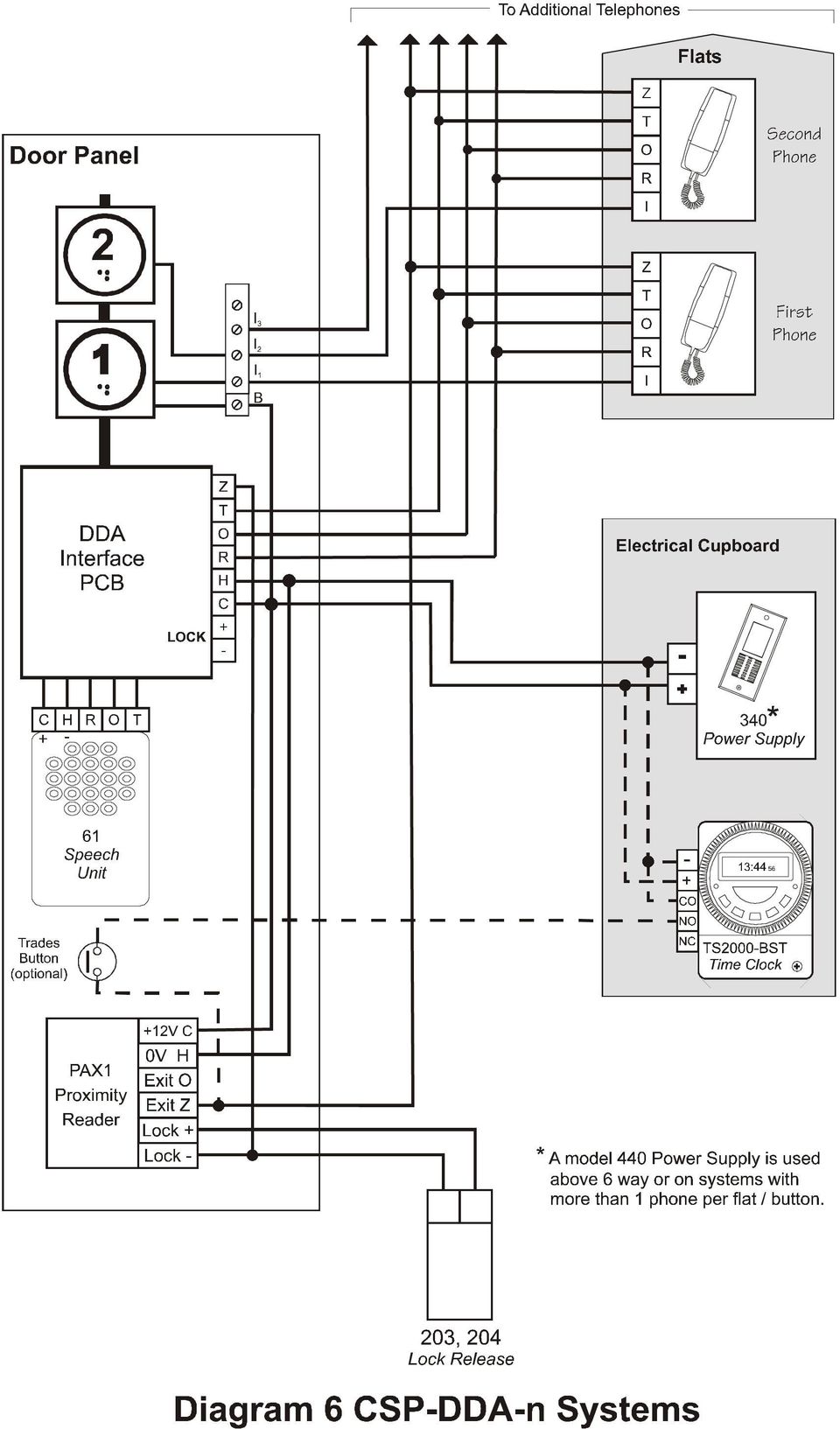
4 Installation of the Door Entry Telephone system From an electrical point of view, the combined systems may be regarded as separate door entry and proximity access systems with the exception of a common lock release. The wiring diagrams show the wiring connections for the Door Entry Telephone system including the simple connections which interface with the Paxton reader. The model 801 Telephone This is designed to be wall mounted in a convenient indoor location. The Entrance panel The entrance panel, containing the speech unit and Paxton reader is supplied with either a surface or flush mounting back-box. It should be mounted on an outside wall near the front door and in a sheltered location. Extension Phones Each apartment can have up to 3 extension phones (4 phones in total). Tradesman Button This is used in conjunction with a time-clock to allow tradesmen access during restricted hours. The time-clock (preferably Bell System model TS2000-BST) may be 12v DC or 240V AC operated but MUST have a voltage-free isolated contact. Cable Requirements For optimum clarity of speech it is strongly recommended that this system is installed using twisted-pair telephone cable (e.g. type CW1308). Use one of the pairs for the R & O connection between the speech unit and the telephone. Cable types; 0.5mm: 1.0mm: Twisted pair, e.g. BT spec CW mm 2 Twin and Earth Connections No. of cores Core diameter Cable length Phone per phone 0.5mm 100M max. Power Supply 2 0.5mm 1.00mm up to 3M up to 12M Lock release (0.5A) 2 0.5mm 1.00mm up to 5M up to 25M Time clock 4 0.5mm 100M max Exit 2 0.5mm 100M max Trades Button 2 0.5mm 100M max In most cases cable length restrictions should not present a problem, however, where longer lengths are required please refer to the manufacturer for advice.

5 Power Supply Important Information The model 340 power supply must be wall mounted on to plasterboard, wood or a similar non-conductive material, in a protected indoor environment and close to a 240V AC electrical supply e.g. an electrical cupboard. Connections to the 240V AC mains supply must be carried out by a qualified electrician or similar competent person, and made in accordance with accepted safety practices. A two-pole switch (as provided by a Consumer Unit or Switch-Fuse) must be included to isolate both the Live and Neutral during installation or maintenance. The circuit must be protected by a fuse or other current limiting devise, rated according to the capacity of the cable used, up to a maximum of 10A. Fuse The transformer is protected by a fuse; always replace this with the correct type and rating: T200mA 250V (20mm glass fuse, 200mA, 250V, Time delay, approved to BS EN or equivalent) Mains Cables Use only mains cable to BS6004, BS6500 or equivalent within the following specified limits: Minimum Maximum Conductor diameter 1.0mm (0.75mm 2 ) 2.25mm (4mm 2 ) Cable Diameter 4.0mm 8.0mm When fitting the cables (both primary and secondary) ensure that the cable entry cut-outs in the enclosure lid are no larger than necessary for the cable diameter used and under no circumstances must they be taken beyond the outer cut-out zones. Installation Procedure Connect all items by following the wiring diagrams at the rear. It is strongly recommended that a single telephone be connected at a time and fully tested before proceeding to the next. Speech adjustment The model 61 speech unit has two pots at the rear for adjustment of speech levels as follows: Volume A: Volume B: speech level at the entrance panel speech level at the telephone
 must be included to isolate both the Live and Neutral during installation or maintenance.")
6 Introduction to the Paxton compact proximity reader This compact panel-mount reader is manufactured by Paxton Access for the exclusive use of Bell System. It can accommodate up to 10,000 keyfob users. It is mounted on the rear of the front door panel by four secure threaded studs and nuts and protected on the front by a lens with properties equivalent to LEXAN. The terminal block has simple connections without the need for complex additional controllers or power supplies. The lock output is fail-secure as a default with a timed lock output set at 7 seconds. Alternatively, the fail-open card (included in the starter keyfob pack) can be used to change the lock output to operate a fail-safe lock release or magnetic lock Suitability; Reader The reader is designed for access control situations where the level of security does not require that the control electronics be on the safe side of the door. It has a capacity of 10,000 keyfob users. Read range The proximity compact reader has a read range of 55mm when using keyfobs in normal conditions. Environment The reader will operate between 20 o C and +70 o C. Proximity keyfob Keyfobs are for applications where convenience is important. They are made of hard plastic and will fit onto a key-ring. They can be attached to car/house keys for reduced losses, hence reducing the cost of replacing fobs. Locks 12V DC Fail-secure or Fail-safe locks (inc. Maglocks) can be used with a maximum current rating of 0.5A. Lock releases of up to 1A maybe driven directly from the reader with a suitable power supply. Fail-secure (Fail closed) Fail secure devices require power to unlock, i.e. if there is no power to the device it is locked. Most standard electric releases are fail secure. If battery backup is not fitted, mains loss would result in doors being locked for the period of the power failure. Fail secure devices are more efficient than fail safe devices, this is because they are only powered when the door is unlocked Fail-safe (Fail open) Fail-safe devices require power to lock, i.e. if there is no power to the device it is unlocked. An example of a fail-safe device is a magnetic lock (Maglock). A failsafe locking device is a requirement for fire doors. This is because it is not reliant on electrical power to unlock. It is advisable to have a battery backup for systems using fail-safe devices. Otherwise a mains power failure would lead to doors unlocking for the period of the mains failure. Fail-safe devices are inefficient in terms of power consumption when compared to fail secure devices. This is because they are powered for the majority of the time, i.e. when the door is locked.
 can be used to change the lock output to operate a fail-safe lock release or magnetic lock Suitability; Reader The reader is")
7 Commissioning Initialising the system After the system has been wired up, be sure to check over the connections against the wiring diagrams provided BEFORE powering up for the first time. When the system is powered up for the first time all the LEDs will be lit. After just a couple of seconds all the LEDS will start flashing. - Present the PROXIMITY enrolment card to the reader (The unit beeps twice and then all the LEDs will light) The three user Keyfobs provided with the starter pack will now work! Checking the system Now that the system has been initialised, the operation of the system will need to be checked. The system will be working as per the default settings (see System Default Settings in the Operation section) - Check that the keyfobs work by trying the three provided. - Check that the door opens when a valid keyfob is used. (The green LED on the reader should flash) - Check that the PROXIMITY reader beeps every time a valid card is presented - If an exit button is wired in, check it opens the door when pressed. (The green LED on the reader should flash) - Check that a user can be barred from the system by presenting a corresponding shadow token to the reader. (The LEDs will briefly go out and the reader will beep twice) Now present the barred token. (The reader will emit a long low tone beep and the red LED will flash) The door should NOT open. - Re-enrol the barred keyfob by presenting the Enrolment Card to the reader. (The LEDs will go out and the reader will beep for 30 seconds) Present the keyfob within this time. (The reader will beep 4 times quickly and all the LEDs will come back on) Check the keyfob now works. To set up the system with other features, see Operation.

8 Operation Proximity keyfobs All users of the system carry round the proximity user keyfob. They can gain access through a door by presenting the keyfob to the reader. If the corresponding colour LED on the reader is lit then the user can enter, assuming they have not been barred. If the keyfob is accepted the green LED will flash (the red and amber go out) and the door can be opened. If the keyfob is not accepted then the red LED will flash (all the other LEDs will go out) and the door will not open. Note: The reader will beep each time a valid keyfob is used unless the system is set for silent operation. Shadow cards To bar a user from entering an area guarded by a reader, the shadow card is used. Present the shadow token to the reader (the reader beeps twice quickly). If the barred user now tries to use the reader to gain entrance, their access will be denied (the red LED will flash and the reader will emit a long low tone beep). Programming using function cards The function cards are used to alter system features. Some function cards come in the starter pack and others come in the function card pack. Starter Pack (included in the kit) Each CSP system includes a starter keyfob pack consisting of; - One Enrolment card - One fail-open release card - Three Proximity user keyfobs (green) - Three user shadows Additional user keyfob packs can be purchased to the required number. The full Function card pack can be considered for further features or functions. Enrolment card This card is used to both initialise the system, re-enrol barred users and enrol new and additional user keyfob packs. It can be presented once to initialise the system after it is first powered up (See Initialising the system). THIS CARD MUST BE KEPT IN A SAFE LOCATION SINCE IT IS REQUIRED IN THE ENROLLING PROCEDURE FOR ADDITIONAL USER KEYFOB PACKS If a user has been barred from a door and needs to be re-enrolled the Enrolment card is used with the user keyfob. Re-enrol the barred keyfob by presenting the Enrolment card to the reader (the LEDs will go out and the reader will beep continuously for 30 seconds) Present the user keyfob within this time (the reader will beep 4 times quickly and all the LEDs will come back on). Check the User keyfob now works.
 and the door will not open.")
9 Fail Open Release card The output of the compact will be in 1 of 2 states, either supplying 12V or 0V DC to the lock continuously. By default the compact is set-up for fail closed releases and so only supplies 12VDC to the lock when a valid card is used or when the exit button is pressed. This card is used to toggle the output of the lock wires. Each time the card is presented to the reader the output will change (the LEDs will go out and the reader will beep twice quickly). Keyfob User Packs (not included in the kit) Additional keyfob packs are available to order to the required number of system users. The default supplied with the system is green. A 'shadow card' system is used for ease of management and the keyfobs are supplied with a wallet for storing the shadow cards. When installing the system the Starter keyfob pack is added by presenting the Enrolment card from that pack. Subsequent packs are added by presenting the original Enrolment card followed by the Enrolment card from the new pack. Further configuration is achieved by using the cards in the pack. Door Open Time card The door open time card is used to adjust the time the door is held open for. To adjust the time: - Present the PROXIMITY Door Open Time card to the reader (all the LEDs go out and the reader beeps once per second) - Present the PROXIMITY Door open Time Card to the reader (all the LEDs come back on) The time between presenting the PROXIMITY Door open time card once and presenting it again sets the time the door is held open for. Fail open release card: Presenting this card reverses the operation of the lock output to make it suitable for operating a fail open release. Presenting this card again reverts operation to the default. Silent Operation card This card is used to toggle the beeping of the reader on and off. By default the reader unit beeps when a keyfob is presented to the reader. If necessary this beep can be silenced by presenting the Silent Operation card to the reader. When the card has been used the amber, green and red LEDs go out. Now the reader will not beep when keyfobs are used with the system. To make the unit beep again when keyfobs are used, simply present the Silent Operation card to the reader again.
 Additional keyfob packs are available to order to the required number of system users. The default supplied with the system is green.")
10 Each keyfob is packaged with a corresponding shadow card. Once installation of the system is complete all user cards are valid and ready to be issued. Keyfobs are available in packs of 10, 25, 50 or 100 users. Ordering information No. of fobs in Pack Green Amber Red G A R G A R G A R G A R Function Card pack (not included in the kit, Paxton Model ) The starter keyfob pack included in the system is sufficient to get the system started and in many installations no further features or functions are required. However, the full Function card pack allows the more advanced features of the proximity system to be utilised. The function card pack includes the following cards; Green, Amber and Red Zone cards These 3 cards toggle the green, amber and red access levels on and off. By default all the levels are active (this means the LEDs on the reader are lit). This in turn allows the green, amber and red user keyfobs access. If the Green zone card is presented to the reader, the green LED will go out and the reader will beep twice quickly. When presented for a second time the green LED comes back on and the reader again beeps twice quickly. This is the same for each colour zone card. If the green LED on the reader is not lit, a user with a green keyfob is denied access (red LED flashes). This is the same for the other coloured LEDs and corresponding keyfobs. Time Zone card This card is used to enable/disable the time zone function. The time zone card simply toggles the control unit between the time zone function being enabled and disabled. By default the time zone function is disabled. If the time zone card is presented to the reader, the reader beeps twice and all the LEDs go out and come back on. The time zone function is now enabled. A time clock can now be programmed and coloured zones can be set up. (To enable/disable coloured zones see Green, Amber and Red Zone cards). To disable the time zone function, just present the Time zone card to the reader. Note : There is no exit button / phone release button input facility when this is enabled, please contact the manufacturer for equipment options if this feature is required. Remote Release card When the system is in Time Zones mode, this card will stop this mode and reenable the exit input for use with an exit button / phone release button.
 The starter keyfob pack included in the system is sufficient to get the system started and in many installations no further features or functions are required.")
11 Bar All Users card This card should be used if the majority of users on the system need to be barred. The card should be presented to the reader once. All the LEDs will go out and come back on, and the reader will beep twice quickly. All users will now be barred. Relay Toggle card This changes the operation of the lock output from a fixed operating time after each valid fob to a toggle/latching output. When enabled the lock output will change state (on or off) when a fob is presented and remain in that state until the next valid fob is presented when it will change to the opposite state and so on. Present the Relay Toggle card again to restore normal operation. This could be used to keep the door open / unlocked for an extended period. Note : The lock release must be continuously rated to use this option. Card Plus PIN card This card is not used on the CSP Combined system System Default Settings System Default Settings User Cards All cards encoded will be valid Zone LED status All LEDs/zones will be on Squeak setting Activated Door Open Time 7 seconds Remote button Activated release for door open time Time Zones Inactive Relay toggle disabled Proximity Reader Re-set WARNING : This procedure will remove all fobs from the system Hardware reset - This procedure should be performed quickly for the reset to be successful. - Power the unit down - Press and hold the exit button - Power the unit up (The Green LED will be lit) - Release the exit button (The Green and amber LEDs are lit) - Press and release the exit button (The Red and amber LEDs are lit) - Press and release the exit button (The unit beeps 3 times and all the LEDs are lit) - WAIT FOR 5 SECONDS! - All the LEDs will now flash. The unit is waiting to be enrolled.
 when a fob is presented and remain in that state until the next valid fob is presented when it will change to the opposite state and so on.")
12 Further Technical Information Bell System (Telephones) Ltd Presley Way Crownhill Milton Keynes MK8 0ET Tel: Fax: website: website: This product complies with European directive 89/336/EEC on Electromagnetic Compatibility and Low Voltage Directive 72/23/EEC. Emissions: Generic BSEN Immunity: Generic BSEN Low Voltage : Generic BSEN 60950

13

14

15

16
Paxton Compact panel Mount Reader
 68 It is common for a door entry telephone system to be combined with a proximity access system to allow easy access by residents, tenants or staff. Distributors have sourced products from two manufacturers
The telephone has three soft-touch silicone rubber push buttons that can be backlit and each has a clear and precise function symbol;
 2 The contemporary and stylistic bellissimo video telephone has a slim and curvaceous profile. It is supplied in white to complement most modern wall furnishings and is now the preferred choice of many
AC-115 Compact Networked Single Door Controller. Installation and User Manual
 AC-115 Compact Networked Single Controller Installation and User Manual December 2007 Table of Contents Table of Contents 1. Introduction...5 1.1 Key Features... 6 1.2 Technical Specifications... 7 2.
Desktop Programmer (DTP)
") INSTALLATION Desktop Programmer (DTP) Keypads & Readers Contents Set up the System...1 RCI DTP Contents...1 Install the System...2 Initialize the Program...2 Initialize the Door Locks...3 Add a User...4
INSTALLATION Desktop Programmer (DTP) Keypads & Readers Contents Set up the System...1 RCI DTP Contents...1 Install the System...2 Initialize the Program...2 Initialize the Door Locks...3 Add a User...4
ACTIVE 5 ENGINEERING MANUAL
 ACTIVE 5 ENGINEERING MANUAL C & K Systems Ltd C031-066 Issue 3 THE ACTIVE 5 INSTALLATION MANUAL. Date: Feb 1997 INTRODUCTION. The Active 5 is a microprocessor controlled intruder alarm panel. It features
PAC1 Door Access Controller
 PAC1 Door Access Controller Series 2 IMPORTANT DIFFERENCES FROM SERIES 1 1. A PACDL data logger revision 4.0 or higher attached to the DLOG terminal is able to program all features (i.e. times, relay type,
D200+ Auto-Dialler Installation/Operators Manual
 D200+ Auto-Dialler Installation/Operators Manual Bell System (Telephones) Ltd. Presley Way, Crownhill, Milton Keynes, MK8 0ET D200+ Software Version 1.0 Contents General Description...3 Central Station
INSTALLATION GUIDE. Card Reader & Controller with KIM Swipe Reader for Solitaire 850 / 950 / 850L Learnlok PK2930
 INSTALLATION GUIDE Card Reader & Controller with KIM Swipe Reader for Solitaire 850 / 950 / 850L Learnlok PK2930 Card Reader and Controller Model 3.5 with KIM Swipe Reader Table of Contents 1. Features..................................
CONTENTS QUICK SETUP & INSTALLATION USER MANUAL. SUPA8 Quick Setup & User Manual
 SUPA8 Quick Setup & User Manual QUICK SETUP & INSTALLATION CONTENTS FACTORY DEFAULTS... 1 INSTALLATION OF THE SECURITY SYSTEM... 2 COMMISSIONING THE DIALLER PANEL... 5 ZONE INPUT CONNECTIONS... 7 PANEL
TS510 & TS500. Installation & User Guide. Compatible Equipment
 Installation & User Guide Compatible Equipment TS510 REM - Remote Keypad 9040 - Loudspeaker DC54/58 - Digital Communicator SD1+ - Speech Dialler 496525 Issue A 1 of 10 TS510 and TS500 Overview Introduction
Adaptability to Enhanced Security
 Installer Guide Adaptability to Enhanced Security AdapTec Plus combines power supply and door access controller features in a compact casing for an encrypted and secure I/O function, enhancing door access
(68.52) X. June 2000 Supercedes February 2000. xenex CONVENTIONAL FIRE DETECTION & ALARM SYSTEM. we look @ business differently
 X. June 2000 Supercedes February 2000. xenex CONVENTIONAL FIRE DETECTION & ALARM SYSTEM. we look @ business differently") (68.52) X June 2000 Supercedes February 2000 xenex CONVENTIONAL FIRE DETECTION & ALARM SYSTEM.... we look @ business differently XENEX SYSTEM ARCHITECTURE Note: This schematic is for guidance only please
(68.52) X June 2000 Supercedes February 2000 xenex CONVENTIONAL FIRE DETECTION & ALARM SYSTEM.... we look @ business differently XENEX SYSTEM ARCHITECTURE Note: This schematic is for guidance only please
Adaptability to Enhanced Security
 Installer Guide Adaptability to Enhanced Security AdapTec Plus combines power supply and door access controller features in a compact casing for an encrypted and secure I/O function, enhancing door access
CM705B - Universal Expander Module CM707B - Plug On Zone Expander Security Systems
 CM705B - Universal Expander Module CM707B - Plug On Zone Expander Security Systems EN Security System CM705B CM705B - Universal Expander Module The CM705B universal expander provides a cost effective way
HAM841K ALARM CONTROL PANEL FOR COMMERCIAL AND RESIDENTIAL SECURITY SYSTEMS
 ALARM CONTROL PANEL FOR COMMERCIAL AND RESIDENTIAL SECURITY SYSTEMS USER MANUAL USER MANUAL ALARM CONTROL PANEL FOR COMMERCIAL AND RESIDENTIAL SECURITY SYSTEMS INTRODUCTION The (HA-841K) is a complete
ICP-CP500. User's Guide ICP-CP500 Codepads
 ICP-CP500 EN User's Guide ICP-CP500 Codepads ICP-CP500 User's Guide 1.0 ICP-CP500 Series Codepads Overview EN 2 1.0 ICP-CP500 Series Codepads Overview The codepad is the communications interface between
CB200W Water Leak Detection Panel Application Guide
 Checked by: AJC Approved by: JBJ Contents CB200W Water Leak Detection Panel Application Guide 1. Cabinet Specifications... 2 2. Panel Hardware Specifications... 3 3. Panel Configuration... 4 4. Technical
Installation manual. Version 1.1. www.videx-security.com
 Installation manual Version 1.1 www.videx-security.com 2 Table of Contents MANUAL INTRODUCTION... 4 SYSTEM INTRODUCTION... 4 SYSTEM COMPONENTS... 5 CONTROLS... 6 3.5A 13.8Vdc PSU... 6 CONTROL PCB... 6
How To Program An Autodialer
 GJD HYL005 GSM Autodialer Instruction Manual Please read these instructions before you start the installation Features: LCD display. Programmable 9 x 32 digit phone numbers for each trigger. 10 second
System Tel 0845 121 4008 (Telephones) Ltd Fax 0845 121 4009 Email [email protected] Web www.bellsystem.co.uk
 Ltd Fax 0845 121 4009 Email technical@bellsystem.co.uk Web www.bellsystem.co.uk") Troubleshooting Guide Audio Door Entry Systems (single entrance) (9nn, VRKn or BLn series) Most systems use the 801 phone, 801P on systems above 20 flats. Twisted-pair cable must be used (CW1308 telephone
Troubleshooting Guide Audio Door Entry Systems (single entrance) (9nn, VRKn or BLn series) Most systems use the 801 phone, 801P on systems above 20 flats. Twisted-pair cable must be used (CW1308 telephone
ATS - Automatic Changeover
 ATS - Automatic Changeover Manufacturers of Electrical Switchgear Choosing an Automatic Transfer System Switchgear Systems offer a variety of solutions for multiple supply switching needs. As well as our
SECURITY ALARM CONTROL PANEL QUICK SETUP & USER MANUAL
 SECURITY ALARM CONTROL PANEL QUICK SETUP & USER MANUAL PINKERTON Quick Setup & User Manual QUICK SETUP & INSTALLATION CONTENTS FACTORY DEFAULTS...1 INSTALLATION OF THE SECURITY SYSTEM...2 COMMISSIONING
INSTALLATION/PROGRAMMING INSTRUCTIONS E4KP ENTRYCHECK
 Security Door Controls 3580 Willow Lane, Westlake Village, CA 91361-4921 (805) 494-0622 Fax: (805) 494-8861 www.sdcsecurity.com E-mail: [email protected] INSTALLATION/PROGRAMMING INSTRUCTIONS E4KP
How To Power A Power Control On An Ip40 (Ipl) With A Power Supply (Iplug) With An Ip20 Controller (Iphones) With Power Control (Power Control) With No Antenna) With The Ip20 (Power)
 With A Power Supply (Iplug) With An Ip20 Controller (Iphones) With Power Control (Power Control) With No Antenna) With The Ip20 (Power)") MODEL NUMBER: ISC910-1-0-GB-XX ISC911-5-0-GB-XX IXP20 CONTROLLER SPECIFICATIONS Working Environment Plastic Housing... Power ImproX IXP20 Controller INSTALLATION MANUAL Designed to work in an indoor (dry)
MODEL NUMBER: ISC910-1-0-GB-XX ISC911-5-0-GB-XX IXP20 CONTROLLER SPECIFICATIONS Working Environment Plastic Housing... Power ImproX IXP20 Controller INSTALLATION MANUAL Designed to work in an indoor (dry)
BARDIC. 4 & 8 Zone Fire Panels Zircon range. Data, installation, operation and maintenance. by Honeywell
 Data, installation, operation and maintenance 4 & 8 Zone Fire Panels Zircon range BARDIC by Honeywell LED flashing LED Continuous FAULT DISABLE/TEST Power General Fault Sounder Fault/ Disable System Fault
500r+ Installation and User Guide
 500r+ Installation and User Guide Compatible Equipment 502rUK-50 Watch/Pendant PA. 509rUK-50 Smoke Detector 515rUK-00 10 metre passive infra red movement detector. 525rUK-00 Remote Set/Unset (Full and
KCIEN KCIENSBP. Heavy Duty Stainless Steel Illuminated Keypads INSTALLATION MANUAL. Range: DIGICODE (Stand-Alone Keypad)
") KCIENSBP KCIEN Heavy Duty Stainless Steel Illuminated Keypads Range: DIGICODE (Stand-Alone Keypad) INSTALLATION MANUAL Features: Input voltage: 12V to 24V AC or 12V to 48V DC Illuminated keys Heavy duty
KCIENSBP KCIEN Heavy Duty Stainless Steel Illuminated Keypads Range: DIGICODE (Stand-Alone Keypad) INSTALLATION MANUAL Features: Input voltage: 12V to 24V AC or 12V to 48V DC Illuminated keys Heavy duty
BREEAM CRITERIA WATER LEAK DETECTION SYSTEM Type WG2 - CONTROL PANEL CONNECTIONS
 BREEAM CRITERIA WATER LEAK DETECTION SYSTEM Type WG2 - CONTROL PANEL CONNECTIONS WG2 Dimensions: LxHXW: 26 x 14.5 x 29.5 cm INTERNAL Alarm Terminals EXTERNAL Alarm Terminals WG2 Control Unit WaterGuard
PK5500 v1.1 Installation Instructions
 PK5500 v1.1 Installation Instructions 1 2 3 4 5 6 7 8 9 * 0 # WARNING: Please refer to the System Installation Manual for information on limitations regarding product use and function and information on
contents Leading the way in intelligent automation INELS Wireless? Why Click Accessories Complete control
 Wireless Control Systems Accessories Leading the way in intelligent automation contents Range Overview Typical Installations Transmitters Combined Modules Accessories Programming Switching & Dimmer Functions
www.sebury.com.cn Digital Keypad Use s Manual
 K3 K4 www.sebury.com.cn Digital Keypad Use s Manual Contents Introduction Introduction Specifications Intramural Interface Circuit 3 Mounting 3 Wiring 5 Power UP 7 Engineer Programming Mode 7 The K3/K4
EQUIPMENT SPECIFICATIONS
 EQUIPMENT SPECIFICATIONS IC-1600 Intelligent Controller The IC-1600 Intelligent Controller is a fully intelligent panel that has a complete database on board. It operates in conjunction with the Access
Speech Dialler Engineering Information
 Speech Dialler Engineering Information Description The Informa is a Speech Dialler for use with intruder alarm systems. When the control panel recognises an alarm it triggers the Informa. The Informa uses
Drayton Digistat +2RF/+3RF
 /+3RF Programmable Room Thermostat Wireless Model: RF700/22090 Model: RF701/22092 Power Supply: Battery - Thermostat Mains - Digistat SCR Invensys Controls Europe Customer Service Tel: 0845 130 5522 Customer
HARDWIRED CONTROL PANELS
 USER GUIDE 9651 HARDWIRED CONTROL PANELS Contents 1. Introduction...3 The Alarm System...3 The Keypad...3 About This Guide...5 2. Everyday Operation...6 How Do I Know if the System is Working?...6 Setting
How To Control A Car Alarm On A Car With A Remote Control System
 MODEL CA100 REMOTE CONTROL AUTO ALARM SYSTEM INSTALLATION & OPERATION INSTRUCTIONS WIRING DIAGRAM Black Antenna Wire 6 Pin 6 Pin Mini Connector Valet Switch Blue LED Indicator Blue Wire: (-) 200mA Unlock
VR8. User Guide Intruder Alarm System
 VR8 EN User Guide Intruder Alarm System VR8 User Guide Notices EN 2 Copyright Notice Unless otherwise indicated, this publication is the copyright of Bosch Security Systems Pty Ltd ( Bosch ). All rights
SECURIT 800L+ CONTROL PANEL
 USER MANUAL SECURIT 800L+ CONTROL PANEL COMPANY PROFILE IntelliSense have been successfully making security products for over 20 years and lead the security industry throughout the world with many innovative
GSM AD05 Slave GSM Auto Dialer- Instruction Manual
 GSM AD05 Slave GSM Auto Dialer- Instruction Manual Please read these instructions before you start the installation Features LCD display Programmable 9 x 32 digit phone numbers for each trigger. 10 second
9452/9453 Installation and User Guide
 9452/9453 Installation and User Guide Compatible Equipment 9425 Remote Keypad 9040 Internal Sounder 660 Speech Communicator 8440 4-Channel Minicom 496330 Issue 1 1 of 10 9452/3 Introduction The 9452 and
NELSON VOLTAGE MONITOR INSTALLATION & PROGRAMMING MANUAL
 NELSON VOLTAGE MONITOR INSTALLATION & PROGRAMMING MANUAL CONTENTS GENERAL INFORMATION...3 INSTALLATION...3 FIELD WIRING...4 PROGRAMMING...4 Circuit Monitor Options...5 Power Frequency...5 Alarm Silence
Emergency Voice Communication Systems EVCS Network 8 Data Sheet
 Emergency Voice Communication Systems EVCS Network 8 Data Sheet The Emergency Voice Communications System (EVCS) Network 8 is for use as a Fire Telephone system, Disabled Refuge Call system or as a combined
Master Time Clock MTC-200 MTC-400 MTC-600. Users Manual
 Master Time Clock MTC-200 MTC-400 MTC-600 Users Manual Toll Free (888)713-0373 Phone (972)987-4408 FAX (877)720-9291 www.midwest-time.com [email protected] TABLE OF CONTENTS TOPIC PAGE GENERAL DESCRIPTION
Installation Guide for Hive Active Heating
 Installation Guide for Hive Active Heating Important note: Installation should only ever be carried out by a qualified engineer. Technical Support If you need to contact Hive s Technical Support team during
Power Socket (2 Gang)
") Version 2.1 Power Socket (2 Gang) Model No. LW270 Instruction Manual Connect Series www.lightwaverf.house EC DECLARATION OF CONFORMITY Responsible Authority: LightwaveRF PLC, Innovation Campus Birmingham
Version 2.1 Power Socket (2 Gang) Model No. LW270 Instruction Manual Connect Series www.lightwaverf.house EC DECLARATION OF CONFORMITY Responsible Authority: LightwaveRF PLC, Innovation Campus Birmingham
EDA-Z5008 & Z5020. Radio Fire Alarm System. User Manual
 EDA-Z5008 & Z5020 Radio Fire Alarm System User Manual Electro-Detectors Ltd. Electro House, Edinburgh Way Harlow, Essex, CM20 2EG UK Tel: 01279 635668. Fax 01279 450185 Email: [email protected]
Technical Overview Add-on Sensors - Smoke Alarm. Get yours direct at: 01491 410913 www.theclimate.co.uk
 Technical Overview Add-on Sensors - Smoke Alarm Get yours direct at: 01491 410913 www.theclimate.co.uk OVERVIEW This kit contains a standard smoke alarm and relay pattress. The Kidde Smoke Alarm supplied
Conventional Fire Detection and Extinguishant Control System Specification
 Conventional Fire Detection and Extinguishant Control System Specification Page 1 of 9 Scope Furnish a complete 24VDC Conventional, electrically supervised, combined fire detection and extinguishant release
WEA-Base. User manual for load cell transmitters. UK WEA-Base User manual for load cell transmitters Version 3.2 UK
 WEA-Base User manual for load cell transmitters 1 Contents 1. Technical data... 3 2. Assembly... 4 2.1 Power supply... 4 2.2 Load cells... 4 2.3 RS-485... 4 2.4 Relays... 5 2.5 Digital input... 5 2.6 Analogue
User Manual. Before installation and use, please read the user manual carefully.
 Sebury Technology Co., Ltd. Address: 5/F, Building 8, Xinwu Industrial Park, Xili, Nanshan District, Shenzhen, China. Tel: +86-755-88856 Fax: +86-755-888565 P.C.: 58055 www.sebury.com.cn User Manual Before
Emergency voice communications Product Name
 Product Name 76 EATON FIRE AND VOICE ALARM SYSTEMS CFCC2556 January 2015 Contents Contents Emergency voice communications Panels Network exchange units 78 Non network exchange units 80 Devices Outstations
Matrix 424/832/832+ ICON & LCD User Manual. Software Version 5 RINS915-2. EN50131-1 Security Grade 2 Environmental Class 2
 Matrix 424/832/832+ ICON & LCD User Manual Software Version 5 RINS915-2 EN50131-1 Security Grade 2 Environmental Class 2 CONTENTS CHAPTER 1: INTRODUCTION... 1 CHAPTER 2: REPLACING THE BATTERIES... 2 CHAPTER
GST301. (Single Protection Zone) Operation Manual
 Operation Manual") GST301 Gas Extinguishing Control Panel (Single Protection Zone) Operation Manual 2 of 19 CONTENTS 1 OVERVIEW... 4 2 TECHNICAL DATA... 4 3 STRUCTURES... 5 3.1 FRONT SURFACE DESCRIPTION... 5 3.1.1 Indicators...
GST301 Gas Extinguishing Control Panel (Single Protection Zone) Operation Manual 2 of 19 CONTENTS 1 OVERVIEW... 4 2 TECHNICAL DATA... 4 3 STRUCTURES... 5 3.1 FRONT SURFACE DESCRIPTION... 5 3.1.1 Indicators...
FIREDEX 2200. Conventional Fire Panels
 68 Flexible, high specification system Choice of 1, 2, 4 or 8 zones Simple one-shot auto-reset user test facility Approved to EN54 Maintenance free poly switch circuit protection, with auto reset Class
WATER LEAK DETECTION SYSTEM WLDS-10 INSTALLATION & COMMISSIONING
 WATER LEAK DETECTION SYSTEM WLDS-10 INSTALLATION & COMMISSIONING DESCRIPTION: An electronic control panel used in conjunction with one pulse meter (water meter with pulse output proportional to flow rate)
GSM Autodialer Professional GJD700 Speech & Text Autodialer
 Text Edit message GSM Autodialer Professional GJD700 Speech & Text Autodialer Introduction The GSM Autodialer Professional works in conjunction with standard alarm systems and makes use of your preferred
Memcom Emergency Telephone
 Memcom Emergency Telephone Installation Guide Ref No. 450 900 (GB) Version 2 + + Simple wiring for quick installation + + Integrated LCD display shows you what you have programmed + + All code based programming
ANTI-THEFT SYSTEM. 1995 Volvo 850 DESCRIPTION & OPERATION BASIC ALARM. 1995-96 ACCESSORIES & EQUIPMENT Volvo Anti-Theft Systems
 ANTI-THEFT SYSTEM 1995 Volvo 850 1995-96 ACCESSORIES & EQUIPMENT Volvo Anti-Theft Systems 850 DESCRIPTION & OPERATION WARNING: Deactivate air bag system before performing any service operation. For 1995
WIRELESS STATUS MONITOR
 INSTALLATION INSTRUCTIONS WIRELESS STATUS MONITOR (WSM or AUWSM) The most current version of this document is available for download at: http://www.ir-swa.com P/N: M053-032-D Schlage 245 W. Roosevelt Road,
Alarm Security Kit - NVR
 Alarm Security Kit - NVR EN The alarm configuration menu (see above right screenshot) allows you to configure and change settings for the PIR movement sensors, window/door sensors, remote controls (key
AUTODIALLER / QUICKDIALLER - SA132
 AUTODIALLER / QUICKDIALLER - SA132 INSTRUCTION LEAFLET ENGLISH www.thermomax-group.com CONTENTS 1 SETUP AT A GLANCE... 2 2 FOREWORD....... 3 3 INSTALLATION...... 4 4 KEYPAD AND INDICATORS...... 5 SETTING
Secure Keypads for access control
 torm Secure Keypads for access control Strike Master Read this manual carefully before attempting to install, program or operate the STORM AXS Strike Master Keypad. After installation the Command Summary
USER MANUAL CHARGING STATIONS FOR ELECTRIC VEHICLES
 USER MANUAL CHARGING STATIONS FOR ELECTRIC VEHICLES 204.CAxxx 204.CBxxx 204.UBxxx 204.WBxxx MP36289 1 ZP90856-GB-6 INDICE 1 SYSTEM DESCRIPTION... 4 1.1 MODES OF OPERATION... 4 2 USER INTERFACE... 6 2.1
BURGLAR ALARM SYSTEMS BURGLAR ALARM SYSTEMS BURGLAR ALARM SYSTEM EURO ALARM WIRELESS BURGLAR ALARM SYSTEM OASIS
 BURGLAR ALARM SYSTEMS BURGLAR ALARM SYSTEMS BURGLAR ALARM SYSTEM EURO ALARM WIRELESS BURGLAR ALARM SYSTEM OASIS BURGLAR ALARM SYSTEM EURO ALARM Six zones with the following connection capabilities: One
Advantium 2 Plus Alarm
 ADI 9510-B Advantium 2 Plus Alarm INSTALLATION AND OPERATING INSTRUCTIONS Carefully Read These Instructions Before Operating Carefully Read These Controls Corporation of America 1501 Harpers Road Virginia
DORMA MODEL PS-406BB POWER SUPPLY INSTALLATION INSTRUCTIONS
 Features: INSTALLATION Install in accordance with NFPA 70. DORMA MODEL PS-406BB POWER SUPPLY INSTALLATION INSTRUCTIONS Up to 1.95 Amps Load Capacity Class 2 Rated Outputs Overload, Over Voltage, and Short
PS 29M DUAL CHANNEL BELTPACK IN METAL CASE
 PS 29M DUAL CHANNEL BELTPACK IN METAL CASE USER MANUAL October 2013 This product is designed and manufactured by: ASL Intercom BV Zonnebaan 42 3542 EG Utrecht The Netherlands Phone: +31 (0)30 2411901 Fax:
4000 Series audio door entry system (using 9307.1 power supply) Installation Instructions IN9307.1
 Installation Instructions IN9307.1") Unit, AM Business Park umberland Avenue Park Royal, London, NW 7QL t : f : w : www.doorentrydirect.com 4 Series audio door entry system (using 7. power supply) Installation Instructions IN7. 7 Getting
Unit, AM Business Park umberland Avenue Park Royal, London, NW 7QL t : f : w : www.doorentrydirect.com 4 Series audio door entry system (using 7. power supply) Installation Instructions IN7. 7 Getting
RUST ELECTRONICS LTD. Remote Switching Unit RCU-O4
 RUST ELECTRONICS LTD Remote Switching Unit RCU-O4 MAINS REMOTE SWITCHING UNIT RCU-O4 The RCU-O4 is a radio remote controlled switching unit that will allow the remote operation of any appropriate electrical
HyperAccess Access Control System
 Control System We manufacture, an advanced PC based access control solution that will give you control over who has access to your building. With you can control access on hundreds of doors for up to 10,000
D24 ALARM CONTROL PANEL USER S MANUAL REVISION 1.1 A$12.00 INC GST
 D24 ALARM CONTROL PANEL USER S MANUAL REVISION 1.1 A$12.00 INC GST Ness Security Products Pty Ltd Quality Endorsed Company ISO9001 LIC.No. QEC2074 NSW Head Office only WWW.NESS.COM.AU Australia s largest
WITURA CORPORATION SDN BHD
 WT 1010SA Stand Alone GSM Alarm System User Manual and Installation Instructions Version: 1.2 Updated: 4 JAN 2012 WITURA CORPORATION SDN BHD Stand Alone GSM Alarm System Instruction Manual 1 Introduction:
Speech Dialler Engineering Information
 Speech Dialler Engineering Information Description The ADE Informa is a Speech Dialler for use with intruder alarm systems. When the control panel recognises an alarm it will trigger the Informa. The Informa
Current valve. for AC 24 V pulse/pause control of electrical loads up to 30 kw
 4 937 DESIO Current valve for AC 24 V pulse/pause control of electrical loads up to 30 kw SEA45.1 Use The current valve is used for the control of electric heating elements in heating, ventilation and
THE BASICS DOOR ENTRY AND ACCESS CONTROL SYSTEMS. Intercoms R Us Ltd 2013 (c)
") THE BASICS DOOR ENTRY AND ACCESS CONTROL SYSTEMS SYSTEM PLANNING Intercoms R Us Ltd 2013 (c) Forward thinking and planning is essential and will save a lot of hassle in the long run and will ensure that
THE BASICS DOOR ENTRY AND ACCESS CONTROL SYSTEMS SYSTEM PLANNING Intercoms R Us Ltd 2013 (c) Forward thinking and planning is essential and will save a lot of hassle in the long run and will ensure that
ESP 120 M1, ESP 208 M1, ESP 240 M1, ESP 415 M1, ESP 277 M1, ESP 480 M1 and M1R variants. Installation instructions ESP M1/M1R mains protectors
 ESP 120 M1, ESP 208 M1, ESP 240 M1, ESP 415 M1, ESP 277 M1, ESP 480 M1 and M1R variants Installation instructions Contents Key points of installation Before installation Installation Installation check
Premier M Plus & Infinity 8
 25 Years of Manufacturing Excellence Premier M Plus & Infinity 8 Conventional Fire Alarm Systems 007 Assessed to ISO 9001: 2008 Certificate number 330 Premier M Plus 8-24 Zone Conventional Fire Alarm Panel
How To Use A Ds340 (Dsp)
") Ideal for monitoring dust levels in the exhaust gas of industrial combustion or air filtration processes. Innovative Dynamic Detection Principle (DDP) measurement technique Immune to gradual reductions
Ideal for monitoring dust levels in the exhaust gas of industrial combustion or air filtration processes. Innovative Dynamic Detection Principle (DDP) measurement technique Immune to gradual reductions
HUNTER-PRO 32 Ver. 3.8 Intruder Alarm System RXN-9/416 User Guide
 HUNTER-PRO 32 Ver. 3.8 Intruder Alarm System RXN-9/416 User Guide PIMA Electronic Systems Ltd. 5 Hatzoref Street, Holon 58856, Israel +972-3-5587722 +972-3-5500442 [email protected] http://www.pima-alarms.com
EVC40 EMERGENCY VOICE COMMUNICATION SYSTEM
 EVC40 EMERGENCY VOICE COMMUNICATION SYSTEM INSTALLATION MANUAL Protec Fire Detection PLC, Protec House, Churchill Way, Nelson, Lancashire, BB9 6RT. Telephone: +44 (0) 1282 717171 Fax: +44 (0) 1282 717273
HM-W536 Install Guide
 HM-W536 Install Guide 9/13/2013 IMPORTANT SAFETY INSTRUCTIONS Warning - When using electrical devices, basic safety precautions should be followed to reduce the risk of fire, electrical shock or injury.
FIRE ALARM SYSTEM TECHNICAL SPECIFICATIONS Page 1 of 10
 TECHNICAL SPECIFICATIONS Page 1 of 10 FIRE DETECTION AND ALARM SYSTEM Scope Furnish a complete 24V DC conventional, electrically supervised, zone annunciated, fire detection and alarm system as specified
Contractors Guide Central Inverter System Installation
 Contractors Guide Central Inverter System Installation Step By Step Procedures 2,200 Watt/VA 6 Step Installation 1. Mount Bottom Cabinet 2. Mount Top Cabinet 3. Install Batteries 4. Install Conduit 5.
User s Information Guide R1A
 HSC505-R Home Security Controller - User Manual Release R1a Pi HSC505 and Pi HSC505R Home Security Controller User s Information Guide R1A Page 1 QD Dynamics (Pty) Ltd reserves the right to make changes
Security. Alarm central unit. Ref.-No. KNX Alarm central unit EAM 4000
 Security Alarm Central Unit 3 4 Technical KNX Alarm central unit EAM 4000 ETS-product family: Alarm system Product type: Alarm central unit The alarm central unit is a modern alarm system using the KNX
Disabled Toilet Alarm. Contractor Pack. Installation & Operating Instructions
 Disabled Toilet Alarm Installation & Operating Contractor Pack Installation & Operating Instructions 1 Overview The Channel Safety Systems Disabled Toilet alarm contractor Packs are an efficient way of
TX3 Series TELEPHONE/CARD ACCESS SYSTEMS. System Introduction (Sales Training)
") TX3 Series TELEPHONE/CARD ACCESS SYSTEMS System Introduction (Sales Training) The new TX3 is designed to provide the best performance and value in stand alone or fully integrated system configurations:
TX3 Series TELEPHONE/CARD ACCESS SYSTEMS System Introduction (Sales Training) The new TX3 is designed to provide the best performance and value in stand alone or fully integrated system configurations:
INSTALLATION INSTRUCTIONS
 LIGHTING CONTROL PANELS 4 AND 8 RELAYS INSTALLATION INSTRUCTIONS INSTALLATION OVERVIEW The installation instructions contained in this document are provided as a guide for proper and reliable installation.
Security System User Guide
 Security System User Guide Contents 1. Introduction... 1 Controls and Displays... 3 Displays... 3 Controls:... 4 2. Everyday Operation... 5 Access to the System... 5 Entering and Leaving the Protected
Accenta/Optima. Engineer s Manual. Honeywell Security. 8SP399A - Accenta mini panel with remote LCD keypad and communicator outputs.
 Reset Chime Omit Prog Set Power PA Day ZONE PA PA Accenta/Optima Engineer s Manual Power Gen" ACCENTA! " # $ % & Zones Power Attack Tamper Day 0 1 2 3 5 6 7 8 Chime Omit Reset Prog 4 9 Set Accenta/! mini
Remote management via the internet. Cost effective. Saved data. EASY door controller. designed by. www.easydoorcontroller.com
 emote management via the internet Cost effective Easy wiring and programming Saved data designed by www.easydoor.com ESY door CCESS CONTOL SPECILIST ESY door Product Easy wiring Simple programming of the
Outdoor 33.6W Dual Port Passive Power-over-Ethernet Midspan For External Security Cameras and Wireless Access Points
 Outdoor 33.6W Dual Port Passive Power-over-Ethernet Midspan For External Security Cameras and Wireless Access Points Features SELV Compliant No Detection Passive Injector Gigabit Compatible Full Protection
PK-01. Standalone door control module. SATEL sp. z o.o. ul. Schuberta 79 80-172 Gdańsk POLAND tel. + 48 58 320 94 00
 Standalone door control module PK-01 Firmware version 1.00 pk-01_en 06/12 SATEL sp. z o.o. ul. Schuberta 79 80-172 Gdańsk POLAND tel. + 48 58 320 94 00 [email protected] www.satel.eu WARNINGS Read carefully
SECURIT 800L+ CONTROL PANEL
 INSTALLATION MANUAL SECURIT 800L+ CONTROL PANEL With additional options CONTENTS Warnings 2 Standards 2 Warranty Statement 2 Product Description 2 Available Parts 2 Intended use 2 Specifications 3 Processor
HAI Access Control. The HAI Access Control Card Reader can be used for:
 HAI Access Control HAI Access Control allows you to access doors by opening an electric or magnetic lock, arm and disarm the security system, and achieve many home automation functions such as controlling
AlarmSense 2-wire detection and alarm system. Product Guide
 AlarmSense 2-wire detection and alarm system Product Guide Contents What is AlarmSense? 2 The purpose of AlarmSense 4 How AlarmSense works 4 Alarmsense Features 5 Detector removal monitoring 5 Priority/non-priority
2 WIRE video door entry system
 J J N P CLASSE 00 VE WIRE video door entry system 5 Description Front view WIRE handsfree colour video handset with inductive loop, preset for different types of installations, depending on the accessories
INSTALLATION MANUAL VEHICLE SECURITY SYSTEM CE-SS200
 INSTALLATION MANUAL VEHICLE SECURITY SYSTEM CE-SS200 FUSION CULTURE TABLE OF CONTENTS There s no point doing something if no one notices. We ve always believed the way to make things happen is by getting
Business/Home GSM Alarm System. Installation and User Manual
 Business/Home GSM Alarm System Installation and User Manual Brief Introduction: GSM 900/1800/1900 bands, can be used in most parts of the world Full duplex communication with the host Monitor the scene
MAKING MODERN LIVING POSSIBLE. AK-SC255 On-Site Installation Guide DANFOSS ELECTRONIC CONTROLS & SENSORS
 MAKING MODERN LIVING POSSIBLE AK-SC255 On-Site Installation Guide DANFOSS ELECTRONIC CONTROLS & SENSORS How to Use This Guide Read this Guide completely as you install and start up your new AK-SC 255 controller.