Session 13 Design for Injection Moulding
|
|
|
- Jemimah Brown
- 10 years ago
- Views:
Transcription
1 Session 13 Design for Injection Moulding Lecture delivered by Prof. M. N. Sudhindra Kumar Professor MSRSAS-Bangalore 1

2 Session Objectives At the end of this session the delegate would have understood Applying DFM to Injection-Molding Thermoplastic Parts Properties of Thermoplastic materials and its process Characteristics of Injection molded parts and its effects Different way of designing injection molded parts through the Design recommendations Manufacturability of plastic parts 2

3 Session Topics Thermoplastic materials The Manufacturing Process Typical Characteristics of Injection- Molded Parts Effects of Shrinkage Economic Production Quantities Design Recommendations Design Guidelines Computer Simulations of Injection-Molding Dimensional Factors And Tolerance Recommendations Design for Manufacturability 3

4 Thermoplastic materials Synthetic Organic chemical compounds High molecular weight? They soften or liquefy when they are heated and solidify when they are cooled. When cooled, they are relatively tough and durable and suitable for a wide variety of product applications. 4

5 Mold? Molding? 5

6 THE PROCESS: The plastic material is received by the molder in granular form??? It is placed in the hopper of an injection-molding machine, from which it is fed to a heated cylinder. Mold defines final shape as material cools and solidifies 6

7 THE PROCESS: As the granules heat in the cylinder, they melt, or plasticize(t g ) A typical melting temperature is about 180 C (350 F), although this varies with different materials and molding conditions The mold, usually of steel, is clamped in the machine and is water-cooled 7

8 8

9 THE PROCESS: The mold is opened, and the molded part with its attached runners is removed The process, with the occasional exception of part removal, is automatic It requires about 45 s/cycle, more or less, with most of that time being devoted to cooling of the material in the mold 9

10 THE PROCESS: Very high pressures, on the order of 70,000 kpa (10,000 lbf/in2) or more, are required during injection. 10

11 Can this assembly be replaced by a single piece molded design? 11

12 12
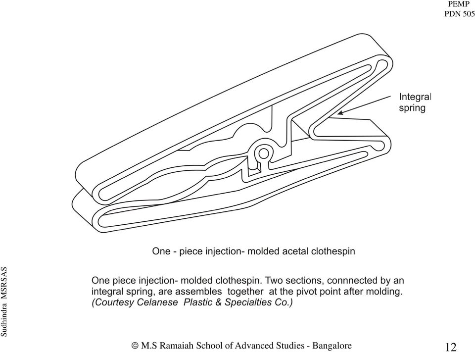
13 TYPICAL CHARACTERISTICS OF INJECTION- MOLDED PARTS: Intricate parts in large quantities One molded part can replace what would otherwise be an assembly of components 13

14 Characteristics of injection- molded parts: Color and surface finish often can be molded directly onto the part, so that secondary finishing operations are not necessary(painting???) Generally thin-walled. Heavy sections and variable wall thicknesses are possible, though they are normally not recommended. 14

15 Characteristics of injection- molded parts: Generally less strong than metals More apt to be found in less highly stressed applications Housings and covers are common uses rather than, for example, frames and connecting rods. 15

16 Characteristics of injection- molded parts: Gradually being developed with better and better strength characteristics and are increasingly finding themselves used for moving parts and in more structural applications (Engine Parts???) 16

17 Characteristics of injection- molded parts: Some Engineering plastics Nylon Polycarbonate Acetal Phenylene oxide Polysulfone Thermoplastic polyesters & others, particularly when reinforced with glass or other fibers, are functionally competitive with zinc, aluminum, and even steel. 17

18 Effects of Shrinkage All thermoplastics exhibit shrinkage on cooling and solidification Causes various irregularities and warpage in the molded part Most common such defect is the sink mark, or surface depression, opposite heavy sections. 18

19 19

20 One Effect of Shrinkage 20

21 Second Effect of Shrinkage 21
22 Third effect of shrinkage 22
23 ECONOMIC PRODUCTION QUANTITIES: >10,000 A unique mold for each part Production must be large enough so that the mold cost can be amortized over the quantity manufactured. 23
24 Relationship between Mech. Properties of Plastics & Moldability Mechanical Properties Low (PE, PP, PS) High (PC, Alloyed Grades..) Moldability High Low 24
25 Suitable Materials: PVC, though low in cost and having very good physical properties, is more difficult to injectionmold than many other materials PVC s prime drawback is a narrow temperature range between its melting and degradation points 25
26 Properties,Cost & applications of Thermoplastics 26
27 DESIGN RECOMMENDATIONS: Gate and Ejector-Pin Locations The designer(?) should consider the location of these elements Ejector pins usually can be located on the underside of a part if it has an outside and an underside 27
28 Various Gating systems 28
29 Various Gating systems 29
30 Various Gating systems (Difference?) 30
31 Thin part No weld line for circular part! Various Gating systems 31
32 Various Gating systems 32
33 Gate and Ejector-Pin Locations Desirable gate locations for trouble-free mold filling Center gating of round and cylindrical parts Near-center gating of other large-area parts 33
34 Suggested Wall Thickness Generally, thinner walls are more feasible with small parts rather than with large ones The limiting factor in wall thinness is the tendency for the plastic material in thin walls to cool and solidify before the mold is filled The shorter the material flow, the thinner the wall can be(?) 34
35 35
36 Suggested Wall Thickness Walls also should be as uniform in thickness as possible to avoid warpage from uneven shrinkage. When changes in wall thickness are unavoidable, the transition should be gradual, not abrupt. (See next Slide) 36
37 37
38 Redesign 38
39 39
40 Comment on this design 40
41 41
42 Design Recommendations: Holes Holes are feasible in injection-molded parts but are a complicating factor in mold construction and part quality "Knit" or "weld" lines adjacent to the hole often develop, and flashing also may occur at the edge of the hole. (See next slides) 42
43 43
44 Holes Minimum spacing between two holes or between a hole and side-wall should be one diameter. PEMP Comment on this design? 44
45 Holes Minimum spacing between two holes or between a hole and side-wall should be one diameter. 45
46 46
47 47
48 Design Guidelines: Holes A through hole is preferred to a blind hole Why? 48
49 Design Guidelines: Holes A through hole is preferred to a blind hole Because the core pin that produces the hole can then be supported at both ends Resulting in better dimensional location of the hole and avoiding a bent or broken pin. 49
50 Design Guidelines: Holes Holes in the bottom of the part are preferable to those in the side because the latter require retractable core pins 50
51 Design Guidelines: Holes Blind holes should not be more than two diameters deep. If the diameter is 1.5 mm or less, one diameter is the maximum practical depth. 51
52 Design Guidelines: Holes Blind holes should not be more than two diameters deep. If the diameter is 1.5 mm or less, one diameter is the maximum practical depth. 52
53 To increase the depth of a deep blind hole, use steps. This enables a stronger core pin to be employed.? 53
54 To increase the depth of a deep blind hole, use steps. This enables a stronger core pin to be employed. 54
55 Similarly, for through holes, cutout sections in the part can shorten the length of a small-diameter pin. (See Fig ) 55
56 Similarly, for through holes, cutout sections in the part can shorten the length of a small-diameter pin. (See Fig ) 56
57 Use overlapping and offset mold-cavity projections instead of core pins to produce holes parallel to the mold-parting line (perpendicular to the mold-movement direction). 57
58 Comment on this design 58
59 59
60 Design Guidelines: Ribs Reinforcing ribs should be thinner than the wall they are reinforcing To prevent sink marks in the opposite side of the wall. Recommended rib thickness : Between 40% and 60% of the wall thickness. 60
61 Design Guidelines:? Ribs should not be higher than 2.5 to 3.0 times the wall thickness. 61
62 Design Guidelines: Ribs should not be higher than 2.5 to 3.0 times the wall thickness. 62
63 Design Guidelines: Ribs Two ribs may be used, if necessary, to provide the extra reinforcement that would otherwise be provided by a high rib. The ribs should be two or more wall thicknesses apart (??) 63
64 Design Guidelines: Ribs Two ribs may be used, if necessary, to provide the extra reinforcement that would otherwise be provided by a high rib. The ribs should be two or more wall thicknesses apart 64
65 Design Guidelines: Ribs Ribs should be perpendicular to the parting line to permit removal of the part from the mold. 65
66 Sink marks caused by ribs can be disguised or hidden by grooves or surface texture opposite the rib. 66
67 67
68 Sink marks caused by ribs can be disguised or hidden by grooves or surface texture opposite the rib. 68
69 Design Guidelines: Ribs should have a generous draft of 0.5deg to 1.5 deg per side There should be a radius at the base of 25% to 40% of t 69
70 70
71 71
72 72
73 Design Guidelines: Bosses Protruding pads used to provide mounting surfaces or reinforcements around holes If large bosses are needed, they should be hollow for uniformity of wall thickness. 73
74 Ribs aid material Flow for a boss 74
75 Design Guidelines: Bosses Bosses in the upper portion of the mold can trap gases and should be avoided If possible, locate bosses in corners,to aid material flow in filling the mold. If a detached boss is necessary, a connecting rib will aid material flow 75
76 Undercuts Undercuts are possible with injection-molded thermoplastic parts, but they may require sliding cores or split molds External undercuts can be placed at the parting line or extended to the line to obviate the need for core pulls Look at the design of ball pen cap 76
77 COMMENT ON THIS DESIGN 77
78 UNDERCUT Shallow undercuts often may be strippable from the mold without the need for core pulls. If the undercut is strippable, the other half of the mold must be removed first. Then the mold ejector pins can act to strip the part. Next Slide shows the average maximum strippable undercut for common thermoplastics. 78
79 Sequence of actions before stripping? 79
80 80
81 Hex Screw??? 81
82 82
83 Ways of molding threads: Use a core that is rotated after the molding cycle has been completed. This unscrews the part from the mold Put the axis of the external screw at the parting line of the mold,avoiding the need for a rotating core but necessitates a very good fit between mold halves to avoid flash across the threads(omit threads in the area of the parting line) 83
84 Ways of molding threads: If threads with strong holding power are needed, use metal inserts Internal threads can be tapped in almost all thermoplastics, and if the thread diameter is small [5 mm (3/16 in) or less], tapping is usually more economical than molding Self-tapping screws are preferable to tapped or molded threads and a conventional screw 84
85 Ways of molding threads: Make the threads a few, shallow, and of rounded form so that the part can be stripped from the mold without unscrewing. A coarse thread with a somewhat rounded form is preferred for all screw threads because of ease of filling and avoidance of featheredges even if it is removed by unscrewing. 85
86 What should we do to strip the bolt from mold? 86
87 Nomenclature of thread shape??? 87
88 88
89 89
90 90
91 91
92 Design of Inserts: Inserts are useful and practical to provide reinforcement where stresses exceed the strength of the plastic material Sharp comers should be avoided on the portion of the insert that is immersed in the thermoplastic. Knurls on machined inserts should be relatively coarse to permit the material to flow into the recesses There should be a smooth surface where the insert exits from the plastic 92
93 93
94 94
95 The surface exiting from plastic should be smooth 95
96 Seal off plastic from unwanted areas 96
97 97
98 ??? 98
99 99
100 ??? 100
101 101
102 Not sufficiently embedded in plastic 102
103 Sketch a screw driver as being molded Detail the embedded portion inside the polymer handle 103
104 104
105 ? 105
106 106
107 Lettering: The lettering on the part generally should be raised?? 107
108 Lettering: The lettering on the part should be raised (ie) formed by depressed, engraved letters in the mold It is easier to engrave lettering in a mold cavity than it is to machine away the background and leave raised letters. 108
109 Lettering: Sometimes it is desired to have depressed letters on the part and to fill them with paint that contrasts with the color of the plastic material Cavities for filled lettering should be sharp-edged and 0.13 to 0.8 mm wide They should be one-half as deep as wide and should have a rounded bottom. 109
110 110
111 Draft: Usually, deep parts require less draft angle than shallow parts For shallow parts draft should average 1/2deg or more? For deep parts 1/8deg can often be satisfactory Textured surfaces require greater draft. 111
112 Draft: It is highly desirable to incorporate some draft, in the side walls of injection molded parts to facilitate removal of the part from the mold. Drafts as low as 1/4deg are often adequate. 112
113 Draft: Usually, deep parts require less draft angle than shallow parts For shallow parts draft should average 1/2deg or more For deep parts 1/8deg can often be satisfactory Textured surfaces require greater draft. 113
114 Minimum Drafts for some common Materials 114
115 115
116 Corners: Radii and Fillets Sharp corners should be avoided except at the parting line.they interfere with the smooth flow of material and create possibilities for turbulence with attendant surface defects. Sharp comers also cause stress concentrations in the part that are undesirable from a functional standpoint. Fillets and radii should be as generous as possible. A desirable minimum under any circumstance is 0.5 mm, while 1.0 mm is a preferable minimum if part requirements permit 116
117 117
118 Surface Finish Surface polish or textures can be molded into the part. No secondary surface-finishing operations (except, of course, plating, hot stamping, or painting, if desired) are necessary High-gloss finishes are feasible if the mold is highly polished and if molding conditions are correct 118
119 Surface Finish However, dull, matte, or textured finishes are preferred to glossy finishes, which tend to accentuate sink marks and other surface imperfections. Painting of most thermoplastics is feasible but is not recommended if the color can be molded into the part. The latter approach obviously is more economical and gives superior results. If contrasting colors are required, masks can be fabricated and a portion of the part left unpainted. 119
120 PLATING OF PLASTIC PARTS: Feasible for some plastics but is a specialized operation. Surface decorations such as flutes, reeds, and textures should stop short of the parting line so that any partingline flash is easy to remove. 120
121 Comment 121
122 122
123 Flat Surfaces: Flat surfaces are somewhat more prone to show irregularities than gently curved surfaces Since the latter also produce more rigid parts, they are preferable 123
124 Mold Parting Line: Every injection-molded part shows the effect of the mold parting line, the junction of the two halves of the mold. The part (and the mold) should be designed so that the parting occurs in an area where it does not adversely affect the appearance or function of the part. One easy way to do this is to put the parting line at the edge of the part where there is already a sharp corner 124
125 Comment on this positioning of parting line? 125
126 Two reasons??? 126
127 On parting-line:. Parting lines should be straight; i.e., the two mold halves should meet in one plane only. This obviously provides more economical mold construction, but it may not be possible if the part design is irregular. If it is not possible to place the parting line at the edge of the part, cleaning parting line flash is facilitated by having a bead or other raised surface at the parting line as shown in slide 127
128 Comment on the design of parting line 128
129 129
130 On Parting Line: Deliberately offset cavities are helpful in avoiding appearance defects, which may occur if the two mold halves do not line up properly. 130
131 Comment on the design of parting line, where the two mold-halves do not lineup properly? 131
132 132
133 Computer Simulations of Injection-Molding Invaluable to both the product designer and tool designer. Aid in optimizing the material flow in the mold & help avoid or minimize molding problems like shrinkage, warpage, weld lines, and sink marks. Changes in both the mold and the part may result from such a simulation. Problems can be identified before the mold is actually machined. 133
134 134
135 DIMENSIONAL FACTORS AND TOLERANCE RECOMMENDATIONS: Dimensions cannot be held with the precision obtainable with close-tolerance machined metal parts, due to 1. There is materials shrinkage,including variation and unpredictability in the shrinkage. 2. Plastics exhibit a high thermal coefficient of expansion. 135
136 3. Despite automatic-control apparatus for pressure, temperature, and time settings, there is some variation in these factors from cycle to cycle, resulting in slight dimensional variations in molded parts. 4. Mold runners, cooling channels, and gates cannot always be located in the optimal position, leading to differences in how uniformly the material is "packed" in the mold and how uniformly it cools. Some distortion or built-in stresses are unavoidable. 136
137 Plastic parts are usually more flexible than metals.a corollary of the flexibility factor is a lessened need for very close tolerances. Plastic parts, when assembled, often can be deformed slightly if this is necessary to ensure a good fit. Knowledgeable designers take advantage of this fact by designing lips and locating bosses on plastic parts to ensure alignment with mating-part surfaces when necessary. 137
138 138
139 139
140 140
141 141
142 As with other processes, close dimensional tolerances can greatly increase the cost of injection-molded parts. Fine-tolerance molds are costlier than looser-tolerance molds. There are processing-cost increases as well when extra tight dimensional control is needed. For example, closer process controls are needed for pressure, temperature, and cycle time; cycle time may be increased; shrink fixtures may be required after the part has been removed from the mold; and scrap rates will be higher. 142
143 Different plastics materials have different tolerance capabilities. Low-shrinkage materials can invariably be molded with 'closer tolerances. Glass-or mineral-filled materials can be molded more accurately than unfilled materials. Cost Tolerance 143
144 144
145 145
146 INJECTION-MOLDED THERMOPLASTIC PARTS: The use of a greater number of mold cavities tends to reduce the closeness of dimensional control over the molded parts. As a rule of thumb, for each cavity after the first, allowable dimensional. tolerances should be increased by 5 percent. 146
147 For example, a single-cavity mold with an allowable tolerance of +/- 0.1 mm (0.004 in) on a particular dimension should have +/ mm (0.006 in) if the number of cavities is 10 (10X5 percent = 50 percent increase in tolerance). 147
148 Tables and show suggested values for dimensional tolerances for various plastic materials. These tables, developed from data supplied by the Society of the Plastics Industry, represent historic and customary practices prevailing in the plastics-molding industry. Contract forms or other agreements of individual molders may vary. 148
149 149
150 150
151 Design for Manufacture/Assembly After Product DFM Analysis through DFA design each part for manufacturability. PEMP Product DFM through DFA is the cake. Part DFM is the icing on the cake. 151
152 Design for Manufacturability PEMP Quality of Design FORM, FIT FUNCTION 152
153 Design for Manufacturability 153
154 Summary Injection moulding is extensively used to produce intricate parts for engineering and commercial applications from polymer granules Colour, surface finish and even printing often can be obtained directly in moulding without the need of secondary operations Design principles for design of moulded parts need to be followed to obtain required dimensions, avoid component warpage and surface defects particularly uniform wall thickness, design of ribs and bosses Injection moulds need to be designed with appropriate injection,gating and ejection systems, adequate drafts and air vents,heating and cooling systems, with provision for insert moulding and side cores as required Injection moulding requires good control on processing parameters to obtain consistent quality, but produce components with very good part detail, finish and dimensional consistency at a very low cycle time 154
Solid shape molding is not desired in injection molding due to following reasons.
 PLASTICS PART DESIGN and MOULDABILITY Injection molding is popular manufacturing method because of its high-speed production capability. Performance of plastics part is limited by its properties which
Die casting Figure M2.3.1
 Die casting Die casting is a moulding process in which the molten metal is injected under high pressure and velocity into a split mould die. It is also called pressure die casting. The split mould used
What is a mold? Casting. Die casting. Injection Molding Machine. Injection Molding. 2.008 Design & Manufacturing II. Spring 2004
 2.008 Design & Manufacturing II What is a mold? From Webster: a cavity in which a substance is shaped: as (1) : a matrix for casting metal (2) : a form in which food is given a decorative shape Spring
3D Printed Injection Molding Tool ("PIMT") Guide. Objet Ltd.
 Guide. Objet Ltd.") 3D Printed Injection Molding Tool ("PIMT") Guide Objet Ltd. 2 Injection molding is a high speed, automated and versatile process that can produce high precision complex three dimensional parts from a fraction
3D Printed Injection Molding Tool ("PIMT") Guide Objet Ltd. 2 Injection molding is a high speed, automated and versatile process that can produce high precision complex three dimensional parts from a fraction
Single Cavity Mould. Basic Mould Construction. Ejection System. Multi Cavity Mould
 Basic Mould Construction Basic mould construction: Core plate and Core (moving) Cavity plate and cavity (fixed) Other features include Guide pillars / guide bush Sprue bush Locating ring Single Cavity
Craft and Design Application of Injection Moulding (Mobile Phone)
") Craft and Design Application of Injection Moulding (Mobile Phone) 5700 Summer 1999 HIGHER STILL Craft and Design Application of Injection Moulding (Mobile Phone) Support Materials This Support Material
Craft and Design Application of Injection Moulding (Mobile Phone) 5700 Summer 1999 HIGHER STILL Craft and Design Application of Injection Moulding (Mobile Phone) Support Materials This Support Material
Two-Shot Silico e Thermoplastic Medical Molding
 Two-Shot Silico e Thermoplastic Medical Molding Author: Sarah J. Voss, Product Specialist, Medical Co-Authors: Mark Simon, Ph. D. Research & Development Manager Danny Ou, Ph D. Research & Development,
Part and tooling design. Eastman Tritan copolyester
 Part and tooling design Eastman Tritan copolyester Part and tooling design Process Part design Tooling design High cavitation considerations Process Process Project development flow chart Concept OEM generates
NetShape - MIM. Metal Injection Molding Design Guide. NetShape Technologies - MIM Phone: 440-248-5456 31005 Solon Road FAX: 440-248-5807
 Metal Injection Molding Design Guide NetShape Technologies - MIM Phone: 440-248-5456 31005 Solon Road FAX: 440-248-5807 Solon, OH 44139 [email protected] 1 Frequently Asked Questions Page What
p l a s t i c i n j e c t i o n m o l d i n g p a r t 1 p r o c e s s, m o l d a n d m a c h i n e e r i k d e l a n g e
 p l a s t i c i n j e c t i o n m o l d i n g p a r t 1 p r o c e s s, m o l d a n d m a c h i n e e r i k d e l a n g e H R O R o t t e r d a m B r n o U T j o i n t p r o j e c t 1 plastic injection
Metal Injection Molded Parts
 Metal Injection Molded Parts Metal Injection Molding (MIM) is a powder metallurgy process. he difference between MIM and conventional powder metallurgy is that in MIM, metal powder along with binders is
6 Design of Gates. 6.1 The Sprue Gate
 6 Design of Gates 6.1 The Sprue Gate The sprue gate is the simplest and oldest kind of gate. It has a circular cross-section, is slightly tapered, and merges with its largest cross-section into the part.
INJECTION MOULD DESIGN: MARPLEX PVC RESINS
 MACHINE RECCOMENDATIONS PVC requires reciprocating screw injection moulding machine with a plasticising screw to produce homogeneous melt. It is recommended that a shot weight of the part should take two
Kursus i Produktions- og materialeteknologi
 Kursus i Produktions- og materialeteknologi Plastsprøjtestøbning / Injection Molding Basics Short history of plastics 1862 first synthetic plastic 1866 Celluloid 1891 Rayon 1907 Bakelite 1913 Cellophane
Injection Molding Design Guide. Table of Contents
 Injection Molding Design Guide 400 Injection Molding Design Guide Table of Contents Injection Mold Tooling Process Comparison...2 Size Limitations...3 Straight Pull Design...4 Other Geometric Considerations...5
Removing chips is a method for producing plastic threads of small diameters and high batches, which cause frequent failures of thread punches.
 Plastic Threads Technical University of Gabrovo Yordanka Atanasova Threads in plastic products can be produced in three ways: a) by direct moulding with thread punch or die; b) by placing a threaded metal
CHAPTER 2 INJECTION MOULDING PROCESS
 CHAPTER 2 INJECTION MOULDING PROCESS Injection moulding is the most widely used polymeric fabrication process. It evolved from metal die casting, however, unlike molten metals, polymer melts have a high
AN OVERVIEW OF GAS ASSIST
 GAS ASSIST INJECTION MOLDING AN OVERVIEW OF GAS ASSIST April 2010 www.bauerptg.com GAS ASSIST INJECTION MOLDING TECHNOLOGY It is a fact that packing force must be applied and maintained to an injection
Injection molding equipment
 Injection Molding Process Injection molding equipment Classification of injection molding machines 1. The injection molding machine processing ability style clamping force(kn) theoretical injection volume(cm3)
Effects of the MuCell Molding Process
 Effects of the MuCell Molding Process Molding MuCell versus Solid Shot size is reduced Final mold fill is completed with cell growth Little or no Hold Time or Pressure Reduced molded-in stress Less warp
Injection Molding. Materials. Plastics 2.008. Outline. Polymer. Equipment and process steps. Considerations for process parameters
 Outline 2.008 Polymer Equipment and process steps Injection Molding Considerations for process parameters Design for manufacturing, tooling and defects 1 2.008 spring 2004 S. Kim 2 Materials Solid materials
1. Injection Molding (Thermoplastics)
") 1. Injection Molding (Thermoplastics) l Molding: Injection (thermoplastics) INJECTION MOLDING of thermoplastics is the equivalent of pressure die casting of metals. Molten polymer is injected under high
1. Injection Molding (Thermoplastics) l Molding: Injection (thermoplastics) INJECTION MOLDING of thermoplastics is the equivalent of pressure die casting of metals. Molten polymer is injected under high
Philosophy of Troubleshooting Injection Molding Problems
 PLASTICS ENGINEERING COMPANY SHEBOYGAN, WISCONSIN 53082-0758 U.S.A 3518 LAKESHORE ROAD POST OFFICE BOX 758 PHONE 920-458 - 2121 F A X 920-458 - 1923 Philosophy of Troubleshooting Injection Molding Problems
CARL HANSER VERLAG. Herbert Rees. Mold Engineering 2nd edition 3-446-21659-6. www.hanser.de
 CARL HANSER VERLAG Herbert Rees Mold Engineering 2nd edition 3-446-21659-6 www.hanser.de 45 4 General Mold Design Guidelines 4.1 Before Starting to Design a Mold he mold designer starts with the design
ECONOMIC DESIGN OF INJECTION MOLDED PARTS USING DFM GUIDELINES - A REVIEW OF TWO METHODS FOR TOOLING COST ESTIMATION
 ECONOMIC DESIGN OF INJECTION MOLDED PARTS USING DFM GUIDELINES - A REVIEW OF TWO METHODS FOR TOOLING COST ESTIMATION Adekunle Fagade, University of Massachusetts Amherst David Kazmer, University of Massachusetts
DIESEL EFFECT PROBLEM SOLVING DURING INJECTION MOULDING
 RESEARCH PAPERS FACULTY OF MATERIALS SCIENCE AND TECHNOLOGY IN TRNAVA SLOVAK UNIVERSITY OF TECHNOLOGY IN BRATISLAVA 2014 Volume 22, Special Number DIESEL EFFECT PROBLEM SOLVING DURING INJECTION MOULDING
NYLON 6 RESINS CORRECTING MOLDING PROBLEMS A TROUBLE SHOOTING GUIDE
 NYLON 6 RESINS CORRECTING MOLDING PROBLEMS A TROUBLE SHOOTING GUIDE A. TROUBLESHOOTING GUIDE FOR INJECTION MOLDERS. I. INTRODUCTION The source of problems in injection molding of nylon resins can depend
Zinc pressure die Casting Processes 1
 Zinc pressure die Casting Processes Pressure die casting is a process in which molten metal is injected at controlled high velocity and pressure into the cavity of a mould (die) which is usually made of
Glossary of Terms Used in Plastic Injection Mold Manufacturing
 Acceptable Runner/Cavity Ratio: Runner systems designed for high pressure drops to minimize material usage and increase frictional heating in the runner. Annealing: The process of relieving internal stresses
Plastic Injection Molding
 Training Objective After watching this video and reviewing the printed material, the student/trainee will understand the principles and physical operations of the plastic injection molding process. An
Plastic Injection Molds
 Training Objective After watching the program and reviewing this printed material, the viewer will become familiar with the variety, design, and productive use of plastic injection molds. Mold components
INJECTION BLOW MOLDING WITH FDM
 INJECTION BLOW MOLDING WITH FDM 3D PRODUCTION SYSTEMS Time Required Cost Skill Level By Susan Sciortino, Stratasys Inc. OVERVIEW Blow molding is a manufacturing process in which air pressure inflates heated
MIT 2.810 Manufacturing Processes and Systems. Homework 6 Solutions. Casting. October 15, 2015. Figure 1: Casting defects
 MIT 2.810 Manufacturing Processes and Systems Casting October 15, 2015 Problem 1. Casting defects. (a) Figure 1 shows various defects and discontinuities in cast products. Review each one and offer solutions
C O N V E Y O R C O M P O N E N T S C H A I N S B E L T S B E A R I N G S
 C O N V E Y O R C O M P O N E N T S C H A I N S B E L T S B E A R I N G S January 2009 Issue 6 Valu Guide Brackets The Ultimate in Adjustability and Cost Savings Valu Guide brackets are part of a family
Why Plastic Flows Better in Aluminum Injection Molds
 Why Plastic Flows Better in Aluminum Injection Molds An investigative study directly comparing melt flow characteristics of general purpose resins in QC-10 aluminum molds and P20 steel molds. By: David
General Injection Mould Specifications KONGSBERG AUTOMOTIVE GROUP
 KONGSBERG AUTOMOTIVE GROUP Edition 3 19.06.2013 A: GENERAL STATEMENT B: STEEL/COLUMN/STANDARD ELEMENTS STEEL COLUMN STANDARD ELEMENTS C: TECHNICAL CHARACTERISTICS I- MOULD BASE GENERAL CONTENT II- MOULD
Fundamentals of Design for Plastic Injection Molding. Kelly Bramble
 Fundamentals of Design for Plastic Injection Molding Kelly Bramble 1 Fundamentals of Design for Plastic Injection Molding Copyright, Engineers Edge, LLC www.engineersedge.com All rights reserved. No part
Mould and Die Standard Parts
 Mould and Die Standard Parts Tampere University of technology - Tuula Höök Mould standard parts can be divided into the following groups: Standard mould set with guide bars, guide sleeves and other guiding
the runnerless types of molds are explained post molding operations are described the basic methods of applied decoration methods are examined
 Training Objectives After watching the video and reviewing this printed material, the viewer will gain knowledge and understanding of the various plastic finishing processes used in industry and their
Investigation of process parameters for an Injection molding component for warpage and Shrinkage
 Investigation of process parameters for an Injection molding component for warpage and Shrinkage Mohammad Aashiq M 1, Arun A.P 1, Parthiban M 2 1 PGD IN TOOL & DIE DESIGN ENGINEERING-PSG IAS 2 ASST.PROFESSOR
Troubleshooting Guide. PS Injection moulding. Splay marks. Burning (Black streaks) Cool feed zone. Dry material, check source of moisture.
 Cool feed zone. Dry material, check source of moisture.") Troubleshooting Guide PS Injection moulding Splay marks Trapped air that contains moisture Raise nozzle and front zone temperature. Cool feed zone. Wet feed Dry material, check source of moisture. Irregular
Troubleshooting Guide PS Injection moulding Splay marks Trapped air that contains moisture Raise nozzle and front zone temperature. Cool feed zone. Wet feed Dry material, check source of moisture. Irregular
Injection molding overview
 Injection molding overview This injection molding overview is designed to help our customers understand the process of injection molding and mold-making. Please read it fully as it helps to define what
TECHNICAL DATA SHEET GRILON BG-15 S
 TECHNICAL DATA SHEET GRILON BG-1 S Grilon BG-1 S is a heat stabilised PA6 injection moulding grade with 1% glass fibres. Grilon BG-1 S has the following important properties: Excellent surface finish Easy
Gas-Assist Injection Molding: An Innovative Medical Technology
 COVER STORY >> MOLDING Gas-Assist Injection Molding: An Innovative Medical Technology In certain medical device applications, gas-assist molding can provide solutions that conventional injection molding
A Guide to Thermoform Processing of Polypropylene. Introduction
 A Guide to Thermoform Processing of Polypropylene Introduction Thermoforming is the process of heating plastic sheet to a pliable state and forming it into shape. Thermoforming offers processing advantages
TITANIUM FABRICATION CORP.
 TITANIUM FABRICATION CORP. Titanium, Zirconium, and Tantalum Clad Construction General Considerations In many applications, particularly for large pressure vessels designed for high temperature and pressure,
Engineering & Design: Coordinate Dimensioning
 s e c t i o n Section Contents NADCA No. Format Page Frequently Asked Questions (FAQ) -2 1 Introduction -2 2 Section Objectives -3 3 Standard and Precision Tolerances -3 4 Production Part Technologies
Facts About. Industrial gases for better injection molding. This article appeared in the trade journal Kunststoffe plast europe, issue 12/2004.
 Facts About. Industrial gases for better injection molding. This article appeared in the trade journal Kunststoffe plast europe, issue 12/2004. 2 Industrial gases for better injection molding Gas injection
1. Injection Molding. 1.1 Injection machine. 1.2 Selection of injection machine. 1.2.1 Select by injection volume
 1. Injection Molding 1.1 Injection machine The injection machine is a machine that melt plasticize the molding material inside the heating cylinder and inject this into the mold tool to create the molded
PRECISION PROTOTYPING THE ROLE OF 3D PRINTED MOLDS IN THE INJECTION MOLDING INDUSTRY
 By Lior Zonder, Applications Team Leader Nadav Sella, Solutions Sales Manager, Global Field Operations Injection molding (IM) the process of injecting plastic material into a mold cavity where it cools
Lecture slides on rolling By: Dr H N Dhakal Lecturer in Mechanical and Marine Engineering, School of Engineering, University of Plymouth
 Lecture slides on rolling By: Dr H N Dhakal Lecturer in Mechanical and Marine Engineering, School of Engineering, University of Plymouth Bulk deformation forming (rolling) Rolling is the process of reducing
Somos Materials. Injection Molding Using Rapid Tooling
 Somos Materials Injection Molding Using Rapid Tooling Introduction Testing a new design before costly tooling is created can save companies time and money. For many years, the only process available to
PROCESSING OF VARIOUS MATERIALS
 4 PROCESSING OF VARIOUS MATERIALS CHAPTER CONTENTS 4.1 Shaping Processes for Polymers Polymers Manufacturing Processes for Polymers 4.2 Rubber Processing Technology Processing of rubber into finished good
SOLUTIONS FOR MOLD DESIGNERS
 SOLUTIONS FOR MOLD DESIGNERS White Paper Abstract For CAE analysis tools to be truly useful, they must provide practical information that drives design decisions. Moldflow Plastics Advisers (MPA ) solutions
Verification Experiment on Cooling and Deformation Effects of Automatically Designed Cooling Channels for Block Laminated Molds
 International Journal of Engineering and Advanced Technology (IJEAT ISSN: 2249 8958 Volume-4 Issue-5 June 2015 Verification Experiment on Cooling and Deformation Effects of Automatically Designed Cooling
Technical Brief. Thermoforming Processes. Vacuum Forming and Methods
 Processes The process of forming a thermoplastic sheet into a three dimensional shape by clamping the sheet in a frame, heating it to render it soft, then applying differential pressure to make the sheet
Casting. Training Objective
 Training Objective After watching the program and reviewing this printed material, the viewer will learn the essentials of the various metal casting processes used in industry today. The basic principles
INJECTION MOLDING PROCESSING GUIDE Polymer
 FOAMAZOL Chemical Foaming Agents INJECTION MOLDING PROCESSING GUIDE Polymer Foaming Agent INJECTION MOLDING WITH CHEMICAL FOAMING AGENTS Introduction The injection molding of structural foam molded parts
General Guidelines for Building Aluminum Production Injection Molds
 General Guidelines for Building Aluminum Production Injection Molds Using 7000 series Aluminum Mold Plate By David Bank Aluminum Injection Mold Company Rochester, New York 1 Introduction This high strength
Determining the Right Molding Process for Part Design
 Determining the Right Molding Process for Part Design How RIM Molding Advantages Compare with Traditional Production Technologies Page 2 Introduction This White Paper details the part production processes
Figure 1 (end) Updated document to corporate requirements Added text to Paragraph 2.4
 Updated document to corporate requirements Added text to Paragraph 2.4") This specification covers the requirements for application of ELCON Drawer Series Connectors: True Hot Plug, Blind Mating Mixed Signal and Power Connectors. These connectors are designed for use in pluggable
This specification covers the requirements for application of ELCON Drawer Series Connectors: True Hot Plug, Blind Mating Mixed Signal and Power Connectors. These connectors are designed for use in pluggable
INJECTION MOLDING COOLING TIME REDUCTION AND THERMAL STRESS ANALYSIS
 INJECTION MOLDING COOLING TIME REDUCTION AND THERMAL STRESS ANALYSIS Tom Kimerling University of Massachusetts, Amherst MIE 605 Finite Element Analysis Spring 2002 ABSTRACT A FEA transient thermal structural
Glossary. 3D Animation Using computer software to create and animate a three-dimensional representation of image data.
 Glossary # 2D Control Drawing A line drawing showing various views of a product with details such as material, surface finish, volume, tolerances and critical dimensions. 3D Animation Using computer software
SUPERCHIPPER CASTING MAINTENANCE
 INTRODUCTION By design, the Superchipper Rotor is clad in castings which wear during crushing. The castings wear at different rates depending on their location on the rotor, material feed rate, material
DIE CASTING. This process if for high volume, high detail, and value added economically priced cast parts. HOW IT WORKS
 DIE CASTING PROCESS This process if for high volume, high detail, and value added economically priced cast parts. HOW IT WORKS A metal tool is built and attached to a furnace of molten metal Then molten
DUPONT PERFORMANCE POLYMERS
 DUPONT PERFORMANCE POLYMERS SELF TAPPING SCREWS: HOW TO CHOOSE THE RIGHT ONE Self-tapping screws provide an economical means of assembling components, especially where dissimilar materials must be joined
Brick Veneer Construction
 Brick Veneer Construction Check list of suggested tools & support items Claw hammer Tape measure 3/4" [19 or 20] Wood chisel Wood or plastic shims Pry bar Utility knife Caulking and caulking gun Power
2. The mold is closed up and held under hydraulic pressure while the rubber material or compound cures.
 Designing with Rubber Molding Processes Compression Molding Compression molding is the process of placing a pre-load of a rubber material or compound directly in the mold cavity and compressed to the shape
Machine bolt shut-off nozzle type BHP pneumatically or hydraulically controlled
 Machine bolt shut-off nozzle type BHP pneumatically or hydraulically controlled Applications: Thermoplastics (not applicable for PVC) Shut-off mechanism: Bolt shut-off with integrated 2-way actuator pneumatically
APPLYING RAPID TOOLING FOR INJECTION MOLDING & DIE CASTING From a RT users perspective
 APPLYING RAPID TOOLING FOR INJECTION MOLDING & DIE CASTING From a RT users perspective Glenn Anderson Senior Engineer, Research and Development Southco, Inc. RPA/SME Technical Forum on Rapid Tooling 20
Liquid Silicone Rubber TAKES THE HEAT
 Liquid Silicone Rubber TAKES THE HEAT For many of us, the easiest place to find liquid silicone rubber (LSR) is at the auto store. It comes in a tube and can be used to create flexible, formed-in-place
ETP 45 (EXTERNAL TECHNICAL PAPER NUMBER 45)
") TAPPEX THREAD INSERTS LIMITED Masons Road Stratford-upon-Avon Warwickshire CV37 9NT Telephone: +44(0) 1789 206600 Fax: +44(0) 1789 414194 Email: [email protected] ETP 45 (EXTERNAL TECHNICAL PAPER NUMBER
TAPPEX THREAD INSERTS LIMITED Masons Road Stratford-upon-Avon Warwickshire CV37 9NT Telephone: +44(0) 1789 206600 Fax: +44(0) 1789 414194 Email: [email protected] ETP 45 (EXTERNAL TECHNICAL PAPER NUMBER
Lightweighting Custom enewsletter
 MuCell Injection Molding: Unique Process Solutions for Light Weighting Plastic Parts MuCell Injection Molding Brent Strawbridge, Vice President Sales Lightweighting Custom enewsletter AGENDA Technology
ARMSTRONG MOLD GRAPHITE DIE CASTING DIVISION
 ARMSTRONG MOLD CORPORATION GRAPHITE DIE CASTING DIVISION Getting Started The Evolution of GDC The GDC technology was developed as a hybrid of traditional permanent mold, graphite mold and the die casting
Gear PEPSI CAN STOVE INSTRUCTIONS
 Gear PEPSI CAN STOVE INSTRUCTIONS [NOTE: Updated Instructions are now available. The new stove is less likely to develop flame leaks and the fuel/air mixture is improved. Instructions for a simmer ring
Cutting and Shearing die design Cutting die design
 Manufacturing Processes 2 Dr. Alaa Hasan Ali Cutting and Shearing die design Cutting die design A stamping die is a special, one-of-a-kind precision tool that cuts and forms sheet metal into a desired
CLASSIFICATIONS OF INJECTION MOLDS
 CLASSIFICATIONS OF INJECTION MOLDS General Notes The following classifications are guidelines to be used in obtaining quotations and placing orders for uniform types of molds. It is our desire, through
Surface Decoration. Design techniques used to put on the surface of the pottery. Slip Oxides Glaze Embossed Incised Wax on wet Altered from the wheel
 Surface Decoration Design techniques used to put on the surface of the pottery. Slip Oxides Glaze Embossed Incised Wax on wet Altered from the wheel Slip How to apply slip Colored slip is intended to add
Machine nozzle with needle shut-off type HP pneumatically or hydraulically controlled
 Machine nozzle with needle shut-off type HP pneumatically or hydraulically controlled Applications: Thermoplastics (not applicable for PVC) Shut-off mechanism: Needle shut-off with integrated 2-way actuator
Sample Feasibility Study XYZ Company Widget Part Design
 Sample Feasibility Study XYZ Company Widget Part Design Prepared For: XYZ Company 1234 Anywhere Street Any Town, State 12345-6789 Prepared By: Some Engineer Plastics Technology Center Penn State Erie,
TECHNICAL SPECIFICATION SERIES 8000 PRECAST CONCRETE
 TECHNICAL SPECIFICATION SERIES 8000 PRECAST CONCRETE TECHNICAL SPECIFICATION PART 8000 - PRECAST CONCRETE TABLE OF CONTENTS Item Number Page 8100 PRECAST CONCRETE CONSTRUCTION - GENERAL 8-3 8101 General
RAIL ADAPTER SYSTEM DRAFT TC-23-AIMSS CHAPTER 1 1-1 DESCRIPTION
 DRAFT TC-23-AIMSS CHAPTER 1 RAIL ADAPTER SYSTEM 1-1 DESCRIPTION The Rail Adapter System (RAS) consists of a set of lightweight specially modified sections that replace the standard front handguards on
TECHNICAL SPECIFICATION
 THOMAS - G-FLEX GFLEX TECH SPEC CONNECTING INNOVATION JOHANNESBURG TEL: +27 11 794 7594 CAPE TOWN TEL: +27 21 556 5258 POLOKWANE TEL: 015 298 9142 DESIGNER, MANUFACTURER AND DISTRIBUTOR OF PIPE CONNECTION,
Elo Touch Solutions Wall-mounting Kit for the 5501L IDS Touchmonitors
 Installation Manual Elo Touch Solutions Wall-mounting Kit for the 5501L IDS Touchmonitors SW602206 Rev B Table of Contents Chapter 1: Safety Warning... 3 Chapter 2: Kit Contents... 4 Included in Kit...
Common Mechanical Engineering Terms
 Common Mechanical Engineering Terms Ball and Detent (n) A simple mechanical arrangement used to hold a moving part in a temporarily fixed position relative to another part. The ball slides within a bored
DESIGN OF PLASTIC INJECTION MOLD FOR AN AIR VENT BEZEL THROUGH FLOW ANALYSIS (CAE) FOR DESIGN ENHANCEMENT
 FOR DESIGN ENHANCEMENT") DESIGN OF PLASTIC INJECTION MOLD FOR AN AIR VENT BEZEL THROUGH FLOW ANALYSIS (CAE) FOR DESIGN ENHANCEMENT Jitendra Dilip Ganeshkar 1, R.B.Patil 2 1 ME CAD CAM Pursuing, Department of mechanical engineering,
DESIGN OF PLASTIC INJECTION MOLD FOR AN AIR VENT BEZEL THROUGH FLOW ANALYSIS (CAE) FOR DESIGN ENHANCEMENT Jitendra Dilip Ganeshkar 1, R.B.Patil 2 1 ME CAD CAM Pursuing, Department of mechanical engineering,
How to reduce the cure time without damaging the rubber compound during injection molding?
 How to reduce the cure time without damaging the rubber compound during injection molding? 0Introduction This article aims at analyzing the rubber injection process and highlighting the limits that prevent
Effect of Differences Core and Cavity Temperature on Injection Molded Part and Reducing the Warpage by Taguchi Method
 International Journal of Engineering & Technology IJET-IJENS Vol:10 No:06 125 Effect of Differences Core and Cavity Temperature on Injection Molded Part and Reducing the Warpage by Taguchi Method Z. Shayfull*
Top 5 Ways to Cut Machining Costs
 Top 5 Ways to Cut Machining Costs Finding ways to cut your company s costs improves overall profits. If your company requires machining services, learning how to cut machining costs may offer significant
CLEAR-DIVISIONS VARIOFOLD
 CLEAR-DIVISIONS VARIOFOLD Introduction: The following three (3) part specification offers the Standard and Optional features for the CLEAR-DIVISIONS VARIOFOLD moveable The yellow highlighted areas in the
THREE-DIMENSIONAL INSERT MOLDING SIMULATION IN INJECTION MOLDING
 THREE-DIMENSIONAL INSERT MOLDING SIMULATION IN INJECTION MOLDING Rong-Yeu Chang* National Tsing-Hua University, HsinChu, Taiwan 30043, ROC Yi-Hui Peng, David C.Hsu and Wen-Hsien Yang CoreTech System Co.,Ltd.,
SECTION G2: CABLE PROCESSOR MODULE MAINTENANCE
 SECTION G2: CABLE PROCESSOR MODULE MAINTENANCE Cable Processor Module overview WARNING! When tipping the Cable Processor Module back, (after removing the toggle arm pin), use extreme caution not to drop
SECTION 02720 SANITARY SEWER AND STORM DRAIN SYSTEMS
 SECTION 02720 SANITARY SEWER AND STORM DRAIN SYSTEMS PART 1 GENERAL 1.01 SECTION INCLUDES A. The requirements for pipe material and installation in sewer and drainage collection systems. All materials
Lapping and Polishing Basics
 Lapping and Polishing Basics Applications Laboratory Report 54 Lapping and Polishing 1.0: Introduction Lapping and polishing is a process by which material is precisely removed from a workpiece (or specimen)
PTFE Slide Bearings 04/10 149
 04/10 149 1.0 GENERAL INFORMATION In a wide range of applications, PTFE Slide bearings are superior to conventional expansion plates, rollers and rocker arm type supports. They support petrochemical plant,
DUPONT PERFORMANCE POLYMERS Joint Design: A Critical Factor in Strong Bonds GENERAL GUIDELINES FOR ULTRASONIC, VIBRATION AND SPIN WELDING
 DUPONT PERFORMANCE POLYMERS Joint Design: A Critical Factor in Strong Bonds GENERAL GUIDELINES FOR ULTRASONIC, VIBRATION AND SPIN WELDING Introduction Welding techniques for assembling parts molded with
Modeling Curved Surfaces
 Modeling Cylindrical and Curved Theory Views of Cylinders Contour Lines Extruded Surfaces Revolved Surfaces & Cutouts Profile Shape Axis of Revolution Swept Surfaces & Cutouts Profile Shape Path Curves
TRENCHLESS TECHNOLOGY GUIDELINES CLOSE FIT THERMOPLASTIC LINING
 TRENCHLESS TECHNOLOGIES RESOURCE CENTRE TRENCHLESS TECHNOLOGY GUIDELINES SECOND EDITION CLOSE FIT THERMOPLASTIC LINING NEW VERSION AUGUST 2005 1. OVERVIEW The use of liners that are deliberately deformed
Welding of Plastics. Amit Mukund Joshi. (B.E Mechanical, A.M.I.Prod.E)
") Welding of Plastics Amit Mukund Joshi (B.E Mechanical, A.M.I.Prod.E) Introduction Mechanical fasteners, adhesives, and welding processes can all be employed to form joints between engineering plastics.
Welding of Plastics Amit Mukund Joshi (B.E Mechanical, A.M.I.Prod.E) Introduction Mechanical fasteners, adhesives, and welding processes can all be employed to form joints between engineering plastics.
The "DAVID" Steam Engine By Alan Marconett Hobbit Engineering HTTP://WWW.HobbitEngineering.com Alan@HobbitEngineering.
 The "DAVID" Steam Engine By Alan Marconett Hobbit Engineering HTTP://WWW.HobbitEngineering.com [email protected] (c) 2/20/03 The David steam engine is a simple oscillating steam engine, many plans