Solid shape molding is not desired in injection molding due to following reasons.
|
|
|
- Lydia Goodman
- 10 years ago
- Views:
Transcription
1 PLASTICS PART DESIGN and MOULDABILITY Injection molding is popular manufacturing method because of its high-speed production capability. Performance of plastics part is limited by its properties which is not as strong (as good) as metal. There are applications where the available properties of the plastics can be useful. The strength of plastics can be improved with reinforcement of glass fiber, mica, talk etc. Plastics generally have following characteristics, Light weight low density, Low conductivity of heat and electricity insulating properties, Low hardness, Lower strength than metals, Ductile, Dimensional stability- not as good as metal, WALL THICKNESS Solid shape molding is not desired in injection molding due to following reasons. Cooling time is proportional to square of wall thickness. Large cooling time for solid will defeat the economy of mass production. (poor conductor of heat) Thicker section shrink more than thinner section, thereby introduce differential shrinkage resulting in warpage or sink mark etc. (shrinkage characteristics of plastics) Therefore we have basic rule for plastic part design; as far as possible wall thickness should be uniform or constant through out the part. This wall thickness is called nominal wall thickness. If there is any solid section in the part, it should be made hollow by introducing core. This should ensure uniform wall thickness around the core.

2 What are the considerations for deciding wall thickness? It must be thick and stiff enough for the job. Wall thickness could be 0.5 to 5mm. It must also be thin enough to cool faster, resulting lower part weight and higher productivity. Any variation in wall thickness should be kept as minimum as possible. A plastic part with varying wall thickness will experience differing cooling rates and different shrinkage. In such case achieving close tolerance becomes very difficult and many times impossible. Where wall thickness variation is essential, the transition between the two should be gradual. CORNERS When two surfaces meet, it forms a corner. At corner, wall thickness increases to 1.4 times the nominal wall thickness. This results in differential shrinkage and molded-in stress and longer cooling time. Therefore, risk of failure in service increases at sharp corners.

3 SINK MARK IS INEVITABLE. Temperature dependent change in volume - 29% in crystalline and 8% in amorphous-. Compressibility of melt under pressure is 10-15%. On falling temperature of melt in the mould, decrease in volume is more than the increase in volume on relaxation of pressure. Therefore void can not be perfectly filled in. Hence sink mark is inevitable. CHANGE IN VOLUME and DENSITY OF MATERIAL Materials Specific volume AT 20 degree C Specific volume AT 200 degree C % age change cubic-cm / g cubic-cm / g HDPE %

4 (crystalline) PS (amorphous) % Density Density HDPE (crystalline) PS (amorphous) % % To solve this problem, the corners should be smoothened with radius. Radius should be provided externally as well as internally. Never have internal sharp corner as it promotes crack. Radius should be such that they confirm to constant wall thickness rule. It is preferable to have radius of 0.6 to 0.75 times wall thickness at the corners. Never have internal sharp corner as it promotes crack. RIBS for stiffness consideration Ribs in plastic part improve stiffness of the part and increases rigidity. It also enhances mold-ability as they hasten melt flow in the direction of the rib.

5 Ribs are placed along the direction of maximum stress and deflection on nonappearance surfaces of the part. Mould filling, shrinkage and ejection should also influence rib placement decisions. Ribs that do not join with vertical wall should not end abruptly. Gradual transition to nominal wall should reduce the risk for stress concentration. Ribs should have following dimensions. Rib thickness should be between 0.5 to 0.6 times nominal wall thickness to avoid sink mark. Rib height should be 2.5 to 3 times nominal wall thickness. Rib should have 0.5 to 1.5-degree draft angle to facilitate ejection. Rib base should have radius 0.25 to 0.4 times nominal wall thickness. Distance between two ribs should be 2 to 3 times (or more) nominal wall thickness. MOULDABILITY consideration While designing plastic part, pitfalls in achieving quality, consistency and productivity must be considered. It is wrong to assume that shapes can be molded successfully with out any defects. All shapes may not be 100% moldable. To improve the mold-ability injection molding process has to be understood in depth.
 nominal wall thickness.")
6 Part design obviously has to be influenced by the intricacies of the process. Filling phase of the process is influenced by type of gate, location of gate, number of gates, size of gate (also dependent on material viscosity). Gate should be located at such position from where flow path to thickness ratio (flow ratio) is constant in all direction. The difference in flow ratio could be as small as possible. In some cases where thickness variation is unavoidable, melt must flow from thin section to thick section for better mold-ability. Melt flow from thin to thick results in poor molding. The size of gate should not result in excessive pressure drop across it. It should be adequate to handle flow rate required. Resistance to flow and viscosity determines the filling pressure. Filling pressure variation should be gradual and not abrupt. It should be remembered that flow thinner section introduces shearing of melt, resulting in lowering of melt viscosity. This is the shear thinning nature of thermoplastics melt. Filling phase is influenced by wall thickness variation as it introduces variation in resistance to flow in all directions from the gate. Melt is held in cylindrical shape in plasticizing cylinder before injection. When the melt is injected through gate and runner system, melt streams move equally in all directions only when resistance to flow is equal in all direction.

7 It should be realized that variation in wall thickness, hole / slot, variation of mould surface temperature introduces variation in resistance to flow. Therefore melt moves in number of streams with different velocity in different direction and mould does not fill in balanced manner. When melt streams reach boundary at the same time it can be called balanced filling. When some stream reaches the boundary early and some other streams reach late this time lag to complete the filling of part results in induction of molded-in stresses in the part.

8

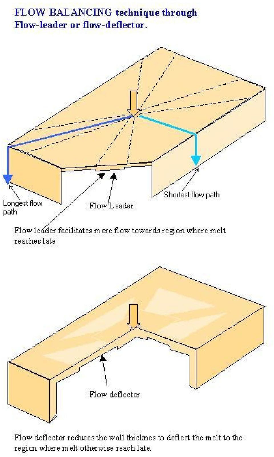
9 Unbalancing flow can be corrected by using flow-leader / flow deflector and multiple gates so as to form the melt stream shape very close to the projected shape of the part.

10
11

12 Ideally all the melt streams should move with the same velocity till the mould is filled. Variation in cross section area (due to changes in wall thickness or slot) introduces variation in melt stream velocity. Hence the freezing of melt can not be uniform through out the part. It should be realized that while freezing, cross section through which melt can flow reduces thereby introducing increasing resistance to flow. When some stream freeze faster then other, faster freezing streams introduce increasing resistance to flow. Therefore, balance in filling can

13 not occur and molded-in stresses are induced. WELD LINE IN MOULDING

14 Weld line occurs when two melt streams join. Melt stream gets divided at cutout (core) in the part and they join at the other end of the cut out. Normally weld line region is filled at the end of injection stroke or during pressure phase. Strength of the weld line is weak when partially frozen melt front meet. The orientation at the joint remains perpendicular to direction of flow -a sign of weakness. Weld line can form by melt stream flowing in same direction or in opposite direction. It is not possible to eliminate weld line, but it can be made sufficiently stronger or its position can be altered. MELT STREAM FROM OPPOSITE DIRECTION

15 CHANGING WELD LINE POSITION

16 Over cooled region can also freeze faster than lesser cooled region. When freezing is not uniform, melt moves through narrowing cross section of slow freezing stream and over packs the slow freezing stream region. Hence uniform mould surface temperature distribution is very important. This has to be achieved through proper design of cooling channels for turbulent water flow.

17 Melt temperature is highest near the gate. Hence freezing is likely to be slower near the gate. This happens near the gate during pressure phase of the process. Here over packing can be controlled through proper profiling of pressure - reducing with time. COOLING consideration Volumetric changes associated with changes in temperature and pressure should be understood well. EJECTION considerations Adequate draft angle, good surface finish, mechanism to handle undercut, strategic location of ejector pins etc should be the consideration of part designer. SUMMARY Design Factors To improve mold-ability, understand the following; Gate Ideally at geometric center of the part. Melt stream shape is similar to projected shape of the part by multiple gate or suitable type and size of the gate. Locate gate at thickness section so that melt flow from thick to thin section. Wall Thickness No variation in wall thickness. Larger the variation means poorer mold-ability. Rib thickness 50 60% of wall thickness. Pressure drop in runner system Runner system should be designed for high pressure drop, thus minimizing material in runner, in order to give low runner to part weight ratio. Flow pattern Distance (L/T ratio) from gate to boundary in all direction, if not same, provide flow leaders or flow deflectors to balance the flow to improve moldability. Lower the difference in L/T ratios in different direction, better the mold-ability. Melt Variation of melt temperature should be with in 10

18 temperature variation in side mould degree centigrade. Shearing through narrow wall increases melt temperature. Filling Pressure The good mold ability occur when pressure gradient i.e. pressure drop per unit length, is constant along the flow path. Maximum Shear Stress The shear stress during filling should be less than a critical value. This critical value depends on material and application. This data is available with Mold flow software. Melt stream velocity Ideally, all melt streams move at same velocity. This can ensure same cooling time for all melt streams. Difference in velocities as less as possible for better mold-ability Avoid hesitation effect Melt flow from thick to thin section is better for mold-ability. Weld-lines Weld-line distance from gate should be as less as possible for better mold-ability. Weld line can be shifted by using frame of suitable thickness. Hold-on pressure Multi steps with reducing pressure with time to avoid molded-in stress near the gate. (not design factor but processing factor) Thermal shut off of runners. The runners must be sized for thermal shut off when the cavity is just filled and sufficiently packed, to avoid over-pack or reverse flow, in and out of cavity, after the mould is filled. Heat exchange Consistent mould temperature can only be ensured

19 when there is balance between heat in and heat out during molding cycle time. Cooling channels must be designed with the help of Mold Flow software. This should ensure uniform cooling time to enhance mold-ability. Core and Cavity dimensions Core and cavity Dimensions computed taking into consideration mould-makers tolerance, mould shrinkage and post molding shrinkage. Easy ejection Proper taper on the part and smooth polished mould surface facilitate easy part ejection. MECHANICAL consideration BOSSES The boss is required for fixing or mounting some other part with screw. It is cylindrical in shape. The boss may be linked at base with the mother part or it may be linked at side. Linking on side may results in thick section of plastic, which is not desirable as it can cause sink mark and increase cooling time. This problem can be solved by linking boss through a rib to the side wall as shown in the sketch. Boss can be made rigid by providing buttress ribs as shown in the sketch.

20 Screw is used on the boss to fasten some other part. There are thread forming type of screws and tread cutting type of screws. Thread forming screws are used on thermoplastics and thread cutting screws are used on inelastic thermo set plastic parts. Thread forming screws produce female threads on internal wall of boss by cold flow plastic is locally deformed rather than cut.

21 Screw boss must proper dimensions to withstand screw insertion forces and the load placed on the screw in service. The size of the bore relative to the screw is critical for resistance to thread stripping and screw pull out. Boss outer diameter should be large enough to withstand hoop stresses due thread forming. Bore has slightly larger diameter at entry recess for a short length. This helps in locating screw before driving in. It also reduces stresses at the open end of the boss. Polymer manufacturers give guidelines for determining the dimension of boss for their materials. Screw manufacturers also give guidelines for the right bore size for the screw. Care should be taken to ensure strong weld joints around the screw bore in boss. Care should be taken to avoid molded-in stress in boss as it can fail under the aggressive environment. Bore in boss should be deeper than the thread depth.
22 Quality of screw connection in plastics Screw connection would obviously be successful only if driving torque is less than the stripping torque. Torque required to drive in the screw is driving torque. The torque required to tear away the internal thread is called stripping torque. Boss should be designed with factor of safety higher than 2. The ratio of stripping torque to driving torque should be more than 2 and preferably 5. Stripping torque depends on Thread size and Boss material.
23 Stripping torque increases as screw penetrates and tends to level off when the screw engagement is about 2.5 times screw pitch. Driving torque depends on Friction and Ratio of bore size to screw diameter. When force required to hold something down exceeds the screw pull out force, the screw thread in the plastics boss will shear off. Pull out force depends on Boss material, Thread dimensions and Length of screw engagement.
What is a mold? Casting. Die casting. Injection Molding Machine. Injection Molding. 2.008 Design & Manufacturing II. Spring 2004
 2.008 Design & Manufacturing II What is a mold? From Webster: a cavity in which a substance is shaped: as (1) : a matrix for casting metal (2) : a form in which food is given a decorative shape Spring
Die casting Figure M2.3.1
 Die casting Die casting is a moulding process in which the molten metal is injected under high pressure and velocity into a split mould die. It is also called pressure die casting. The split mould used
AN OVERVIEW OF GAS ASSIST
 GAS ASSIST INJECTION MOLDING AN OVERVIEW OF GAS ASSIST April 2010 www.bauerptg.com GAS ASSIST INJECTION MOLDING TECHNOLOGY It is a fact that packing force must be applied and maintained to an injection
Part and tooling design. Eastman Tritan copolyester
 Part and tooling design Eastman Tritan copolyester Part and tooling design Process Part design Tooling design High cavitation considerations Process Process Project development flow chart Concept OEM generates
6 Design of Gates. 6.1 The Sprue Gate
 6 Design of Gates 6.1 The Sprue Gate The sprue gate is the simplest and oldest kind of gate. It has a circular cross-section, is slightly tapered, and merges with its largest cross-section into the part.
CHAPTER 2 INJECTION MOULDING PROCESS
 CHAPTER 2 INJECTION MOULDING PROCESS Injection moulding is the most widely used polymeric fabrication process. It evolved from metal die casting, however, unlike molten metals, polymer melts have a high
3D Printed Injection Molding Tool ("PIMT") Guide. Objet Ltd.
 Guide. Objet Ltd.") 3D Printed Injection Molding Tool ("PIMT") Guide Objet Ltd. 2 Injection molding is a high speed, automated and versatile process that can produce high precision complex three dimensional parts from a fraction
3D Printed Injection Molding Tool ("PIMT") Guide Objet Ltd. 2 Injection molding is a high speed, automated and versatile process that can produce high precision complex three dimensional parts from a fraction
DIESEL EFFECT PROBLEM SOLVING DURING INJECTION MOULDING
 RESEARCH PAPERS FACULTY OF MATERIALS SCIENCE AND TECHNOLOGY IN TRNAVA SLOVAK UNIVERSITY OF TECHNOLOGY IN BRATISLAVA 2014 Volume 22, Special Number DIESEL EFFECT PROBLEM SOLVING DURING INJECTION MOULDING
Session 13 Design for Injection Moulding
 Session 13 Design for Injection Moulding Lecture delivered by Prof. M. N. Sudhindra Kumar Professor MSRSAS-Bangalore 1 Session Objectives At the end of this session the delegate would have understood Applying
Effects of the MuCell Molding Process
 Effects of the MuCell Molding Process Molding MuCell versus Solid Shot size is reduced Final mold fill is completed with cell growth Little or no Hold Time or Pressure Reduced molded-in stress Less warp
Injection Molding. Materials. Plastics 2.008. Outline. Polymer. Equipment and process steps. Considerations for process parameters
 Outline 2.008 Polymer Equipment and process steps Injection Molding Considerations for process parameters Design for manufacturing, tooling and defects 1 2.008 spring 2004 S. Kim 2 Materials Solid materials
Two-Shot Silico e Thermoplastic Medical Molding
 Two-Shot Silico e Thermoplastic Medical Molding Author: Sarah J. Voss, Product Specialist, Medical Co-Authors: Mark Simon, Ph. D. Research & Development Manager Danny Ou, Ph D. Research & Development,
Injection molding equipment
 Injection Molding Process Injection molding equipment Classification of injection molding machines 1. The injection molding machine processing ability style clamping force(kn) theoretical injection volume(cm3)
Gas-Assist Injection Molding: An Innovative Medical Technology
 COVER STORY >> MOLDING Gas-Assist Injection Molding: An Innovative Medical Technology In certain medical device applications, gas-assist molding can provide solutions that conventional injection molding
Single Cavity Mould. Basic Mould Construction. Ejection System. Multi Cavity Mould
 Basic Mould Construction Basic mould construction: Core plate and Core (moving) Cavity plate and cavity (fixed) Other features include Guide pillars / guide bush Sprue bush Locating ring Single Cavity
MIT 2.810 Manufacturing Processes and Systems. Homework 6 Solutions. Casting. October 15, 2015. Figure 1: Casting defects
 MIT 2.810 Manufacturing Processes and Systems Casting October 15, 2015 Problem 1. Casting defects. (a) Figure 1 shows various defects and discontinuities in cast products. Review each one and offer solutions
Investigation of process parameters for an Injection molding component for warpage and Shrinkage
 Investigation of process parameters for an Injection molding component for warpage and Shrinkage Mohammad Aashiq M 1, Arun A.P 1, Parthiban M 2 1 PGD IN TOOL & DIE DESIGN ENGINEERING-PSG IAS 2 ASST.PROFESSOR
Structural Integrity Analysis
 Structural Integrity Analysis 1. STRESS CONCENTRATION Igor Kokcharov 1.1 STRESSES AND CONCENTRATORS 1.1.1 Stress An applied external force F causes inner forces in the carrying structure. Inner forces
NetShape - MIM. Metal Injection Molding Design Guide. NetShape Technologies - MIM Phone: 440-248-5456 31005 Solon Road FAX: 440-248-5807
 Metal Injection Molding Design Guide NetShape Technologies - MIM Phone: 440-248-5456 31005 Solon Road FAX: 440-248-5807 Solon, OH 44139 [email protected] 1 Frequently Asked Questions Page What
Injection Molding Design Guide. Table of Contents
 Injection Molding Design Guide 400 Injection Molding Design Guide Table of Contents Injection Mold Tooling Process Comparison...2 Size Limitations...3 Straight Pull Design...4 Other Geometric Considerations...5
Lightweighting Custom enewsletter
 MuCell Injection Molding: Unique Process Solutions for Light Weighting Plastic Parts MuCell Injection Molding Brent Strawbridge, Vice President Sales Lightweighting Custom enewsletter AGENDA Technology
Craft and Design Application of Injection Moulding (Mobile Phone)
") Craft and Design Application of Injection Moulding (Mobile Phone) 5700 Summer 1999 HIGHER STILL Craft and Design Application of Injection Moulding (Mobile Phone) Support Materials This Support Material
Craft and Design Application of Injection Moulding (Mobile Phone) 5700 Summer 1999 HIGHER STILL Craft and Design Application of Injection Moulding (Mobile Phone) Support Materials This Support Material
INJECTION MOULD DESIGN: MARPLEX PVC RESINS
 MACHINE RECCOMENDATIONS PVC requires reciprocating screw injection moulding machine with a plasticising screw to produce homogeneous melt. It is recommended that a shot weight of the part should take two
Metal Injection Molded Parts
 Metal Injection Molded Parts Metal Injection Molding (MIM) is a powder metallurgy process. he difference between MIM and conventional powder metallurgy is that in MIM, metal powder along with binders is
A Guide to Thermoform Processing of Polypropylene. Introduction
 A Guide to Thermoform Processing of Polypropylene Introduction Thermoforming is the process of heating plastic sheet to a pliable state and forming it into shape. Thermoforming offers processing advantages
SOLUTIONS FOR MOLD DESIGNERS
 SOLUTIONS FOR MOLD DESIGNERS White Paper Abstract For CAE analysis tools to be truly useful, they must provide practical information that drives design decisions. Moldflow Plastics Advisers (MPA ) solutions
NYLON 6 RESINS CORRECTING MOLDING PROBLEMS A TROUBLE SHOOTING GUIDE
 NYLON 6 RESINS CORRECTING MOLDING PROBLEMS A TROUBLE SHOOTING GUIDE A. TROUBLESHOOTING GUIDE FOR INJECTION MOLDERS. I. INTRODUCTION The source of problems in injection molding of nylon resins can depend
Troubleshooting Guide. PS Injection moulding. Splay marks. Burning (Black streaks) Cool feed zone. Dry material, check source of moisture.
 Cool feed zone. Dry material, check source of moisture.") Troubleshooting Guide PS Injection moulding Splay marks Trapped air that contains moisture Raise nozzle and front zone temperature. Cool feed zone. Wet feed Dry material, check source of moisture. Irregular
Troubleshooting Guide PS Injection moulding Splay marks Trapped air that contains moisture Raise nozzle and front zone temperature. Cool feed zone. Wet feed Dry material, check source of moisture. Irregular
Fundamentals of Design for Plastic Injection Molding. Kelly Bramble
 Fundamentals of Design for Plastic Injection Molding Kelly Bramble 1 Fundamentals of Design for Plastic Injection Molding Copyright, Engineers Edge, LLC www.engineersedge.com All rights reserved. No part
DUPONT PERFORMANCE POLYMERS
 DUPONT PERFORMANCE POLYMERS SELF TAPPING SCREWS: HOW TO CHOOSE THE RIGHT ONE Self-tapping screws provide an economical means of assembling components, especially where dissimilar materials must be joined
p l a s t i c i n j e c t i o n m o l d i n g p a r t 1 p r o c e s s, m o l d a n d m a c h i n e e r i k d e l a n g e
 p l a s t i c i n j e c t i o n m o l d i n g p a r t 1 p r o c e s s, m o l d a n d m a c h i n e e r i k d e l a n g e H R O R o t t e r d a m B r n o U T j o i n t p r o j e c t 1 plastic injection
TECHNICAL DATA SHEET GRILON BG-15 S
 TECHNICAL DATA SHEET GRILON BG-1 S Grilon BG-1 S is a heat stabilised PA6 injection moulding grade with 1% glass fibres. Grilon BG-1 S has the following important properties: Excellent surface finish Easy
Plastic Injection Molding
 Training Objective After watching this video and reviewing the printed material, the student/trainee will understand the principles and physical operations of the plastic injection molding process. An
DESIGN OF PLASTIC INJECTION MOLD FOR AN AIR VENT BEZEL THROUGH FLOW ANALYSIS (CAE) FOR DESIGN ENHANCEMENT
 FOR DESIGN ENHANCEMENT") DESIGN OF PLASTIC INJECTION MOLD FOR AN AIR VENT BEZEL THROUGH FLOW ANALYSIS (CAE) FOR DESIGN ENHANCEMENT Jitendra Dilip Ganeshkar 1, R.B.Patil 2 1 ME CAD CAM Pursuing, Department of mechanical engineering,
DESIGN OF PLASTIC INJECTION MOLD FOR AN AIR VENT BEZEL THROUGH FLOW ANALYSIS (CAE) FOR DESIGN ENHANCEMENT Jitendra Dilip Ganeshkar 1, R.B.Patil 2 1 ME CAD CAM Pursuing, Department of mechanical engineering,
Weld Line Occurrence in Plastic Injection Molded Parts
 Weld Line Occurrence in Plastic Injection Molded Parts Weld lines, also commonly known as knit lines, may be present in a plastic molded part depending on the parts geometry. This article will review how
1. Injection Molding. 1.1 Injection machine. 1.2 Selection of injection machine. 1.2.1 Select by injection volume
 1. Injection Molding 1.1 Injection machine The injection machine is a machine that melt plasticize the molding material inside the heating cylinder and inject this into the mold tool to create the molded
Glossary of Terms Used in Plastic Injection Mold Manufacturing
 Acceptable Runner/Cavity Ratio: Runner systems designed for high pressure drops to minimize material usage and increase frictional heating in the runner. Annealing: The process of relieving internal stresses
INJECTION MOLDING COOLING TIME REDUCTION AND THERMAL STRESS ANALYSIS
 INJECTION MOLDING COOLING TIME REDUCTION AND THERMAL STRESS ANALYSIS Tom Kimerling University of Massachusetts, Amherst MIE 605 Finite Element Analysis Spring 2002 ABSTRACT A FEA transient thermal structural
Gas-Injection Moulding with DuPont engineering polymers
 Technical Report TRG 3060 Engineering Polymers Gas-Injection Moulding with DuPont engineering polymers Start with DuPont Engineering Polymers DuPont registered trademark Introduction Gas-injection moulding
Plastic Injection Molds
 Training Objective After watching the program and reviewing this printed material, the viewer will become familiar with the variety, design, and productive use of plastic injection molds. Mold components
Injection molding overview
 Injection molding overview This injection molding overview is designed to help our customers understand the process of injection molding and mold-making. Please read it fully as it helps to define what
4 Thermomechanical Analysis (TMA)
") 172 4 Thermomechanical Analysis 4 Thermomechanical Analysis (TMA) 4.1 Principles of TMA 4.1.1 Introduction A dilatometer is used to determine the linear thermal expansion of a solid as a function of temperature.
172 4 Thermomechanical Analysis 4 Thermomechanical Analysis (TMA) 4.1 Principles of TMA 4.1.1 Introduction A dilatometer is used to determine the linear thermal expansion of a solid as a function of temperature.
Verification Experiment on Cooling and Deformation Effects of Automatically Designed Cooling Channels for Block Laminated Molds
 International Journal of Engineering and Advanced Technology (IJEAT ISSN: 2249 8958 Volume-4 Issue-5 June 2015 Verification Experiment on Cooling and Deformation Effects of Automatically Designed Cooling
Mould and Die Standard Parts
 Mould and Die Standard Parts Tampere University of technology - Tuula Höök Mould standard parts can be divided into the following groups: Standard mould set with guide bars, guide sleeves and other guiding
How to reduce the cure time without damaging the rubber compound during injection molding?
 How to reduce the cure time without damaging the rubber compound during injection molding? 0Introduction This article aims at analyzing the rubber injection process and highlighting the limits that prevent
Removing chips is a method for producing plastic threads of small diameters and high batches, which cause frequent failures of thread punches.
 Plastic Threads Technical University of Gabrovo Yordanka Atanasova Threads in plastic products can be produced in three ways: a) by direct moulding with thread punch or die; b) by placing a threaded metal
Injection moulding and modelling on a micro scale
 Injection moulding and modelling on a micro scale Technology Update Injection moulding and welding of plastics 11 November 2014 Research Projects (National / European) Micro/Nano/Multimaterial Manufacturing
Foam Injection Molding:
 Foam Injection Molding: Unique Process Solutions for Light Weighting Automotive Plastic Parts Steve Braig President & CEO Trexel, Inc. AGENDA Technology Overview > Chemical Foaming > Physical Foaming Foamed
Why Plastic Flows Better in Aluminum Injection Molds
 Why Plastic Flows Better in Aluminum Injection Molds An investigative study directly comparing melt flow characteristics of general purpose resins in QC-10 aluminum molds and P20 steel molds. By: David
1. Injection Molding (Thermoplastics)
") 1. Injection Molding (Thermoplastics) l Molding: Injection (thermoplastics) INJECTION MOLDING of thermoplastics is the equivalent of pressure die casting of metals. Molten polymer is injected under high
1. Injection Molding (Thermoplastics) l Molding: Injection (thermoplastics) INJECTION MOLDING of thermoplastics is the equivalent of pressure die casting of metals. Molten polymer is injected under high
CARL HANSER VERLAG. Herbert Rees. Mold Engineering 2nd edition 3-446-21659-6. www.hanser.de
 CARL HANSER VERLAG Herbert Rees Mold Engineering 2nd edition 3-446-21659-6 www.hanser.de 45 4 General Mold Design Guidelines 4.1 Before Starting to Design a Mold he mold designer starts with the design
Unit 6: EXTRUSION. Difficult to form metals like stainless steels, nickel based alloys and high temperature metals can also be extruded.
 1 Unit 6: EXTRUSION Introduction: Extrusion is a metal working process in which cross section of metal is reduced by forcing the metal through a die orifice under high pressure. It is used to produce cylindrical
Effect of Differences Core and Cavity Temperature on Injection Molded Part and Reducing the Warpage by Taguchi Method
 International Journal of Engineering & Technology IJET-IJENS Vol:10 No:06 125 Effect of Differences Core and Cavity Temperature on Injection Molded Part and Reducing the Warpage by Taguchi Method Z. Shayfull*
DIE CASTING. This process if for high volume, high detail, and value added economically priced cast parts. HOW IT WORKS
 DIE CASTING PROCESS This process if for high volume, high detail, and value added economically priced cast parts. HOW IT WORKS A metal tool is built and attached to a furnace of molten metal Then molten
Gas Assist and Microcellular (MuCell ) ) Molding Process. Vishu Shah Consultek
 ) Molding Process. Vishu Shah Consultek") Gas Assist and Microcellular (MuCell ) ) Molding Process Vishu Shah Consultek What is Gas Assist Injection Molding? Gas Assist injection molding is a process enhancement to conventional injection molding,
Gas Assist and Microcellular (MuCell ) ) Molding Process Vishu Shah Consultek What is Gas Assist Injection Molding? Gas Assist injection molding is a process enhancement to conventional injection molding,
Quick Guide to Injection Molding
 Quick Guide to Injection Molding Amodel polyphthalamide (PPA) Equipment Amodel PPA resins can be processed on conventional injection molding equipment. Estimated clamp tonnage of 5.5 kn/cm 2 (4 T/in 2
THREE-DIMENSIONAL INSERT MOLDING SIMULATION IN INJECTION MOLDING
 THREE-DIMENSIONAL INSERT MOLDING SIMULATION IN INJECTION MOLDING Rong-Yeu Chang* National Tsing-Hua University, HsinChu, Taiwan 30043, ROC Yi-Hui Peng, David C.Hsu and Wen-Hsien Yang CoreTech System Co.,Ltd.,
Understanding Plastics Engineering Calculations
 Natti S. Rao Nick R. Schott Understanding Plastics Engineering Calculations Hands-on Examples and Case Studies Sample Pages from Chapters 4 and 6 ISBNs 978--56990-509-8-56990-509-6 HANSER Hanser Publishers,
The EJOT. Fastener. Predictable performance improvement for thermoplastics. EJOT The Quality Connection
 The EJOT Fastener Predictable performance improvement for thermoplastics EJOT The Quality Connection Benefits of the EJOT DELTA PT The product Minimal radial tension due to optimized flank angle High clamp
Kursus i Produktions- og materialeteknologi
 Kursus i Produktions- og materialeteknologi Plastsprøjtestøbning / Injection Molding Basics Short history of plastics 1862 first synthetic plastic 1866 Celluloid 1891 Rayon 1907 Bakelite 1913 Cellophane
Philosophy of Troubleshooting Injection Molding Problems
 PLASTICS ENGINEERING COMPANY SHEBOYGAN, WISCONSIN 53082-0758 U.S.A 3518 LAKESHORE ROAD POST OFFICE BOX 758 PHONE 920-458 - 2121 F A X 920-458 - 1923 Philosophy of Troubleshooting Injection Molding Problems
2. The mold is closed up and held under hydraulic pressure while the rubber material or compound cures.
 Designing with Rubber Molding Processes Compression Molding Compression molding is the process of placing a pre-load of a rubber material or compound directly in the mold cavity and compressed to the shape
Casting. Training Objective
 Training Objective After watching the program and reviewing this printed material, the viewer will learn the essentials of the various metal casting processes used in industry today. The basic principles
1. Fluids Mechanics and Fluid Properties. 1.1 Objectives of this section. 1.2 Fluids
 1. Fluids Mechanics and Fluid Properties What is fluid mechanics? As its name suggests it is the branch of applied mechanics concerned with the statics and dynamics of fluids - both liquids and gases.
ETP 45 (EXTERNAL TECHNICAL PAPER NUMBER 45)
") TAPPEX THREAD INSERTS LIMITED Masons Road Stratford-upon-Avon Warwickshire CV37 9NT Telephone: +44(0) 1789 206600 Fax: +44(0) 1789 414194 Email: [email protected] ETP 45 (EXTERNAL TECHNICAL PAPER NUMBER
TAPPEX THREAD INSERTS LIMITED Masons Road Stratford-upon-Avon Warwickshire CV37 9NT Telephone: +44(0) 1789 206600 Fax: +44(0) 1789 414194 Email: [email protected] ETP 45 (EXTERNAL TECHNICAL PAPER NUMBER
A Systematic Approach to Diagnosing Mold Filling and Part Quality Variations
 VOL. 3 NO. 2 A Systematic Approach to Diagnosing Mold Filling and Part Quality Variations www.beaumontinc.com A Systematic Approach to Diagnosing Mold Filling and Part Quality Variations Applying Fundamental
DESIGN IMAGINEERING DESIGNING YOUR PLASTIC PART KEY DEFINITIONS DESIGNING YOUR PLASTIC PART KEY DEFINITIONS IDEAL CONDITIONS IN PART DESIGN
 DESIGN GUIDELINES FOR PLASTIC DESIGN RTP COMPANY IMAGINEERING DESIGNING YOUR PLASTIC PART DESIGNING YOUR PLASTIC PART When designing parts for injection molding, the manufacturing process must be considered.
General Injection Mould Specifications KONGSBERG AUTOMOTIVE GROUP
 KONGSBERG AUTOMOTIVE GROUP Edition 3 19.06.2013 A: GENERAL STATEMENT B: STEEL/COLUMN/STANDARD ELEMENTS STEEL COLUMN STANDARD ELEMENTS C: TECHNICAL CHARACTERISTICS I- MOULD BASE GENERAL CONTENT II- MOULD
Influence of material data on injection moulding simulation Application examples Ass.Prof. Dr. Thomas Lucyshyn
 TRAINING IN THE FIELD OF POLYMER MATERIALS / PLASTICS Influence of material data on injection moulding simulation Application examples Ass.Prof. Dr. Thomas Lucyshyn 24 th April 2014 Otto Gloeckel-Straße
INJECTION MOLDING PROCESSING GUIDE Polymer
 FOAMAZOL Chemical Foaming Agents INJECTION MOLDING PROCESSING GUIDE Polymer Foaming Agent INJECTION MOLDING WITH CHEMICAL FOAMING AGENTS Introduction The injection molding of structural foam molded parts
General Guidelines for Building Aluminum Production Injection Molds
 General Guidelines for Building Aluminum Production Injection Molds Using 7000 series Aluminum Mold Plate By David Bank Aluminum Injection Mold Company Rochester, New York 1 Introduction This high strength
Fundamentals of Extrusion
 CHAPTER1 Fundamentals of Extrusion The first chapter of this book discusses the fundamentals of extrusion technology, including extrusion principles, processes, mechanics, and variables and their effects
Technical Drawing Specifications Resource A guide to support VCE Visual Communication Design study design 2013-17
 A guide to support VCE Visual Communication Design study design 2013-17 1 Contents INTRODUCTION The Australian Standards (AS) Key knowledge and skills THREE-DIMENSIONAL DRAWING PARALINE DRAWING Isometric
Bending, Forming and Flexing Printed Circuits
 Bending, Forming and Flexing Printed Circuits John Coonrod Rogers Corporation Introduction: In the printed circuit board industry there are generally two main types of circuit boards; there are rigid printed
Somos Materials. Injection Molding Using Rapid Tooling
 Somos Materials Injection Molding Using Rapid Tooling Introduction Testing a new design before costly tooling is created can save companies time and money. For many years, the only process available to
INJECTION BLOW MOLDING WITH FDM
 INJECTION BLOW MOLDING WITH FDM 3D PRODUCTION SYSTEMS Time Required Cost Skill Level By Susan Sciortino, Stratasys Inc. OVERVIEW Blow molding is a manufacturing process in which air pressure inflates heated
Facts About. Industrial gases for better injection molding. This article appeared in the trade journal Kunststoffe plast europe, issue 12/2004.
 Facts About. Industrial gases for better injection molding. This article appeared in the trade journal Kunststoffe plast europe, issue 12/2004. 2 Industrial gases for better injection molding Gas injection
Geometry and dimensional tolerances of engine bearings
 Geometry and dimensional tolerances of engine bearings Dr. Dmitri Kopeliovich (Research & Development Manager.) 1. Hydrodynamic lubrication Engine bearings operate mostly in the hydrodynamic regime of
Balancing the Electrical and Mechanical Requirements of Flexible Circuits. Mark Finstad, Applications Engineering Manager, Minco
 Balancing the Electrical and Mechanical Requirements of Flexible Circuits Mark Finstad, Applications Engineering Manager, Minco Table of Contents Abstract...............................................................................................
Chapter Outline Dislocations and Strengthening Mechanisms
 Chapter Outline Dislocations and Strengthening Mechanisms What is happening in material during plastic deformation? Dislocations and Plastic Deformation Motion of dislocations in response to stress Slip
Crimp Tooling Where Form Meets Function
 Crimp Tooling Where Form Meets Function Quality, cost, and throughput are key attributes for any production process. The crimp termination process is no exception. Many variables contribute to the results.
Eastman polymers. Processing and mold design guidelines
 Eastman polymers Processing and mold design guidelines Proper mold design and machine setup are essential parts of a quality molding operation. This publication is intended to assist you in the design
Zinc pressure die Casting Processes 1
 Zinc pressure die Casting Processes Pressure die casting is a process in which molten metal is injected at controlled high velocity and pressure into the cavity of a mould (die) which is usually made of
A LAMINAR FLOW ELEMENT WITH A LINEAR PRESSURE DROP VERSUS VOLUMETRIC FLOW. 1998 ASME Fluids Engineering Division Summer Meeting
 TELEDYNE HASTINGS TECHNICAL PAPERS INSTRUMENTS A LAMINAR FLOW ELEMENT WITH A LINEAR PRESSURE DROP VERSUS VOLUMETRIC FLOW Proceedings of FEDSM 98: June -5, 998, Washington, DC FEDSM98 49 ABSTRACT The pressure
How To Design A 3D Print In Metal
 DMLS / SLM Metal 3D Printing. An introductory design guide for our 3d printing in metal service. v2.2-8th July 2015 Pricing considerations. Part Volume. One of the biggest factors in the price for DMLS
KALPANA INDUSTRIES LTD. TECHNICAL DATA SHEET
 1 KALPANA INDUSTRIES LTD. TECHNICAL DATA SHEET KI XL - 03 / KI-SC 10 TWO COMPONENT AMBIENT CURABLE POLYETHYLENE COMPOUND FOR INSULATION OF LOW VOLTAGE POWER CABLE DESCRIPTION : KI polyethylene compound
Injection Molding Design Guidelines
 Injection Molding Design Guidelines /resins/include/mainmenu_xml.inc /resins/include/techsolution_xml.inc /resins/include/rate_xml.inc Technical Research Design Guides Injection Molding Design A successful
Determining the Right Molding Process for Part Design
 Determining the Right Molding Process for Part Design How RIM Molding Advantages Compare with Traditional Production Technologies Page 2 Introduction This White Paper details the part production processes
Lecture slides on rolling By: Dr H N Dhakal Lecturer in Mechanical and Marine Engineering, School of Engineering, University of Plymouth
 Lecture slides on rolling By: Dr H N Dhakal Lecturer in Mechanical and Marine Engineering, School of Engineering, University of Plymouth Bulk deformation forming (rolling) Rolling is the process of reducing
Built to Last. Built for Beauty. Good. Solid. Logix. TM
 Built to Last. Built for Beauty. Good. Solid. Logix. TM Quality, Value and Service Introducing LOGIX Insulated Concrete Forms. Based on the simple concept of interlocking blocks, LOGIX ICF gives you a
Lenntech. 1000 psi End port pressure vessels 2.5. User s Guide to: Phoenix Vessel Technology Limited. Model number: 1503
 1 User s Guide to: Phoenix Vessel Technology Limited 1000 psi End port pressure vessels 2.5. Model number: 1503 Lenntech [email protected] Tel. +31-152-610-900 www.lenntech.com Fax. +31-152-616-289 Phoenix
Mounting Instructions for SP4 Power Modules
 Mounting Instructions for SP4 Power Modules Pierre-Laurent Doumergue R&D Engineer Microsemi Power Module Products 26 rue de Campilleau 33 520 Bruges, France Introduction: This application note gives the
Section 16 - Troubleshooting
 Troubleshooting Section 16 - Troubleshooting Introduction This troubleshooting information assumes that the hot runner has been operational. Basic rules for troubleshooting are: Define the problem; what
WORKSHOP P I M. Powder Injection Moulding
 WORKSHOP Mikkelissä ke 22. 5. 2013 P I M Powder Injection Moulding Definition of PIM PIM MIM Injection moulding of metal powders Wittmann Group Injection moulding of powders CIM Injection moulding of
PEEK tm. A Practical Design Guide For Injection Molded Components. www.performanceplastics.com. 4435 Brownway Avenue Cincinnati, OH 45209 513.321.
 PEEK tm A Practical Design Guide For Injection Molded Components www.performanceplastics.com 4435 Brownway Avenue Cincinnati, OH 45209 513.321.8404 Warranty Disclaimer No information supplied by Performance
Introduction to JIGS AND FIXTURES
 Introduction to JIGS AND FIXTURES Introduction The successful running of any mass production depends upon the interchangeability to facilitate easy assembly and reduction of unit cost. Mass production
Injection moulding LFT Long Fibre Thermoplastics
 Injection moulding LFT Long Fibre Thermoplastics Grilamid LVL (PA 12) Grivory HTVL (aromatic PA) Grivory GVL (partially aromatic PA) Grilon TSGL (PA 66+6) Long glass fibre or long carbon fibre reinforced
Injection molding Troubleshooting guide. Eastman copolyesters
 Injection molding Troubleshooting guide Eastman copolyesters Contents Black specks.......................... 3 Brittleness........................... 3 Discoloration......................... 4 Flashing............................
Effect of Sleeve Shrink-fit on Bearing Preload of a Machine Tool Spindle: Analysis using Finite Element Method
 Effect of Sleeve Shrink-fit on Bearing Preload of a Machine Tool Spindle: Analysis using Finite Element Method Aslam Pasha Taj 1, Chandramouli SR 2* ACE Designers Limited, Peenya Industrial Area, Bangalore-560058
POURING THE MOLTEN METAL
 HEATING AND POURING To perform a casting operation, the metal must be heated to a temperature somewhat above its melting point and then poured into the mold cavity to solidify. In this section, we consider