N8LP LP-Remote Assembly and User Manual
|
|
|
- Robyn Gregory
- 10 years ago
- Views:
Transcription
1 1 Assembly and User Manual 1

2 2 Copyright , TelePost Inc. 1.1 Introduction LP-Remote is a combination of hardware and software designed to remotely control a ham station with a combination of serial comm and TCP/IP based serial device server. LP-Remote provides remote control/monitoring of relays - expandable to 64 8 digital logic inputs 6 analog inputs 2 variable analog outputs frequency temperature

3 3 All the remote hardware is buffered and/or isolated from the shack using a combination of opto-isolators, relays and op-amps. The board is thoroughly shielded for rf, and all the critical parts are socketed for quick replacement if necessary. There is a large LCD display with multiple screens for initial setup and maintenance. All connections are made via screw terminals. The software has user name-able buttons for relays, with two modes of operation. Normal mode allows independent operation of all 16 relays. Interlock operation allows the relays to be controlled in two banks of 8, with only one relay activated at a time. This is great for things like antenna switching or rig routing. Each bank can be either normal or interlock with a simple click. The analog meters are very customizable as well, allowing the following parameters to be set up... Meter caption Min and max values number of divisions three color bands with any start/stop value sensitivity polling interval (200ms to 5 sec) There are also 8 digital logic inputs that change color when activated at the remote site. They can also be custom named, as well as 2 variable, 0-5 vdc analog outputs with custom naming. Refer to the schematic for the following discussion... The heart of the hardware board is a 16F877A PIC microcontroller from MicroChip. It provides all the functionality of the board. The PIC provides seven 10-bit A/D inputs (0ne of which is used for the temp sensor), the eight digital logic inputs, two variable dc outputs, LCD/control switch interfacing, frequency counter and serial port. In addition, it interfaces to a pair of MCP23008 port expanders which each provide 8 relay outputs. The interfacing is done through a Serial Peripheral Interface bus, which is brought out to a connector to allow an additional 6 expander chips to be connected externally (48 additional relays or relay drivers). The port expander outputs are connected to the relays using an eight channel Darlington driver chip for each group of relays. I will offer expansion boards in the future which will provide either an additional 16 relays, or 16 Power FET relay drivers per board.

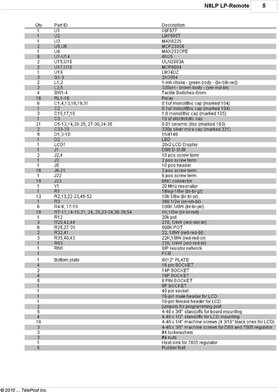
4 4 1.2 Assembly Assembly of the Board To assemble your kit you will need the following: 15-30W soldering iron with fine tip. Thin rosin core solder Small needle nose pliers Small diagonal cutters Small Philips screwdriver Before assembly, compare the supplied parts against the following list of parts to make sure that no parts are missing. Leave components in conductive foam until you are ready to install them. Note: parts values subject to change without notice.


5 5
6 6 Parts locations for all parts are silk-screened onto the top of the PCB, but you can also refer to the following diagram if you have any trouble reading the silk-screened parts. Parts can be assembled in any order, but I recommend installing the DIP sockets first so that the board can lay flat during their installlation. Next I would install the tactile switches and LCD socket, so that they can be held firmly against the board while soldering them. Then I install the small parts like resistors, caps, diodes, chokes, etc. I follow the parts list within these categories, and check off the parts as I go, either individually or in sections. The LED is positioned facing the regulator. I then do the pots, connectors, regulator/heat sink, connectors and finally the relays. The 3/8" x #4 machine screws, #4 lockwashers and nuts are used to hold the heatsink/regulator and DB9 in place. These parts should be screwed down before soldering to minimize lead stress. I recommend installing a half-dozen or so parts, clipping the leads, and then adding another half-dozen. Keeping the number of uncut leads to a minimum will make things easier and less cluttered. The PCB has a solder mask which should make assembly easier, but always take care to not apply too much solder, or it will bridge into the ground fill area. You should read through this entire section before starting assembly to catch all the tips that will make it easier to assemble the kit. It is also a good idea to refer back to the drawing above periodically.

7 7 Before plugging in the ICs, you should do a visual check of the board for obvious solder bridges, missing parts, proper parts orientation, etc. Note: there are a number of pads that are used only to bridge between the top and bottom of the board, so not all pads are associated with parts. Check the resistance of the 5v and 12v buses to make sure there are no shorts. Then install the 5v regulator and power up the board... making sure you have the Gnd and +12v connected properly. Check the 5v bus to make sure you have 5v, before you install the ICs and LCD display, then disconnect the 12v supply. Make sure that your work area is grounded, and that you touch ground before picking up static sensitive components like the ICs. You can now install the ICs. Note: U15 is backward from the other horizontal ICs. Care should be taken when installing the LCD display. First, install the 16-pin male DIL plug on the underside of the display, install the 16-pin female jack and aluminum standoffs on the board. Leave them a little loose to help line them up with the LCD holes. Making sure that the plug is centered over the jack, with equal overhang on each side, plug the LCD panel into the jack... and then screw the display down to the standoffs and tighten the standoffs from the bottom of the board as well. Two jumpers are added to the programming port J5 next. DO NOT SKIP THIS STEP. The display signals loop through these jumpers when a programmer is not connected. Here is a graphic closeup of that section of the board. The gray blocks show where the jumpers go. Counter Input Configuration You should decide at this time whether you will use a small external dipole to feed the counter or bridge the exciter output. The bridge circuit at B is the preferred one, since it automatically provides the right gain range. With this arrangement, the counter has a useable power range of about +10dBm (10mW) to +52dBm (150W). You will need to break the line from your exciter in half, and insert a BNC T connector. The T connects to the LP-Remote counter input. The wide range makes the display more stable when using cw or SSB, as the counter countinues to work between peaks. The input terminating resistor is set for 220 ohms in this instance. The value is

8 8 chosen with a safety margin in mind to account for less than optimum SWR on the exciter line, which could increase voltage. If you run less than 10W, the value could be increased to 1k for greater sensitivity. If you prefer, you can wire the input as in A to allow for direct connection to a small pickup antenna. The sensitivity range with this arrangement -30 dbm (1 microwatt) to +23 dbm (200 milliwatt). This has the advantage of no direct connection to the rig, but will require some playing to determine pickup antenna placement, and you should check the output of the dipole with a scope or diode detector to make sure it is in the correct range without overdriving the counter input. This method may also provide more isolation between the rig and the board. The 50 ohm terminating resistor sets the input Z of the preamp, since the input stage is an emitter follower, and is inherently high Z. If you use this approach, be careful to not overdrive the input. Use the smallest pickup antenna that gives reliable counter operation. Final Assembly Loosely install the hex standoffs to the bottom plate, and then the PCB to the standoffs. They go at the four corners, and one near the switches. After checkout, you can tighten these. Install the rubber feet on the bottom of the plate. Initial Checkout Set R12 (display contrast) to midrange, then power up the board. You should see a "splash" screen for a couple seconds with the program name and copyright info, then the Home screen should appear, as shown below. The frequency should be khz at this point. If you don't immediately see a display, play with the contrast pot.

9 9 If you don't see the display, contact me at or If you see the display OK, continue to Setup and Operation. 1.3 Setup and Operation


10 10 Hardware After verifying that the Home screen is being displayed, you can start checking out the sections of the board. The switch just to the lower left of the LCD display is used to select diagnostic screens. Each press of the button advances to the next screen. There are a total of six screens with wrap-around back to the Home screen. The two switches below and to the right of the LCD display are the Up and Dn switches (left one is Dn). These are used to set the number of relays and for counter calibration. If you have external relay boards, you should advance the Up switch until the "R16" next to the frequency readout shows the correct number of relays (ie, R32, R48 or R64). If you go too far, you will get a write_error message from the PIC. Just hit the Dn button until the display changes back to the correct value for R. The error will dissappear when you have the correct number of relays displayed. The second screen is shown above. This is the analog input screen. To verify proper operation of the analog inputs, use a cliplead to connect each of the analog inputs to +5v in turn. The screw on top of the terminal may not always make good connection until it is tightened, so don't be fooled until you know the connection is solid. Be careful not to touch the cliplead to the GND or REF terminals on the ends of the terminal block. The display should show a positive number, probably near 40. The number 40 represents an input voltage of 4.0v, the maximum input level of the A/D converters. The number is rounded off for ease of display. The actual maximum value is 4.096v, and the resolution of the A/D inputs is 4.096/1024, or.004v per step. To preserve bandwidth and improve the sampling rate of the analog inputs (~10 samples per second for all 6 channels), the values are rounded off to 8-bit accuracy for transmission on the serial port. This provides a resolution of 4.096/256=.016v per step in the software. Since the eye can only resolve about 100 steps on the software meters, this gives more than enough resolution, and allows reading a range of about 1v with full scale accuracy. The software allows you to set any gain or offset, in addition to the gain control in the hardware. This allows almost any indicated range to be displayed, and the zero point does not have to be zero. The inputs to the A/D converters are very high Z, and the gain pot allows you to set the stage gain so that much higher voltages can be sampled. Be careful when using higher voltages to turn the pot down before applying the voltage. remember, the pots

11 11 are 10 turn ones. You should set the gain pot so that the highest voltage you want to display for each channel indicates 40 on the diagnostic screen. This will give you maximum resolution. Fine tuning of the displayed values will be done in software. Advance to the next screen, which is the digital status input screen shown above. Check the inputs by using the cliplead to touch each input to +5v or +12v in turn. Be careful not to touch the cliplead to the GND terminal by mistake. The status on the screen will change from 0 to 1 for each numbered input as you apply the voltage. The status inputs are opto-isolated, and can accept input voltage levels of 5-15vdc. The voltage can come from the board or elsewhere, as long as the ground reference for the voltage is connected to the board, and is clean. The next screen is analog out, shown above. The initial screen will be 00 for each output. The scale is rounded off again, with 50 representing 5.0vdc. The analog outputs can't be checked without the software to send commands, so we will skip this until we install the software and are ready to check it. The same holds true for the relay screens. Above is the first relay screen. There are four, which display the relay status in groups of 16. We will return to this screen after the software is loaded.

12 12 The final screen is the counter calibration screen. This is required because I chose to use a ceramic resonator for the PIC clock to avoid problems with isolation between the high gain counter preamp and an external xtal oscillator. The counter is not meant to be a precision instrument, only a way to verify that you are transmitting on the frequency that you think you are at the remote site. Set your transmitter for 10m if possible, or as high a band as you can. Key your transmitter into an appropriate antenna. In the case of a bridging input from an exciter, just keying the xmtr at minimum power should be more than enough. In the case of a sample from an external antenna, you will need to play with antenna position and xmtr power to get a solid reading to start with. It is recommended you use a higher band like 20m or 10m to allow for easier calibration. If the counter reading is more than 1or 2 khz off, use the Up/Dn buttons to correct the reading. The Trim number will change from the original 00 to indicate that you have applied a correction factor to the counter. The trim value is relative, and does not indicate khz, since the effect of the Trim varies with frequency (biggest changes are on 10m). The Trim value, as well as number of relays, output values like analog voltage levels and relay status are saved in non-volatile memory so that a loss of power or reboot of the board will retain the current status of the board. Software

13 13 To install the software, just click on setup.exe on the CD. If you download newer versions of the software from the TelePost website, you will have to unzip the file and place it in a temp directory first. Follow the instructions for the default installation. If you get a warning about already having a newer version of certain system files on your computer, click to keep your current ones as opposed to installing the older ones from the CD. Once the program is installed, connect the computer to the LP-Remote board. Go to the Start menu and select LP-Remote. The program will launch and look like the above, but without any frequency or temperature data. At this time, it will create default registry entries for all the adjustable parameters such as meter settings, button names and status input names, as shown above. It will start in the "diagnostic" mode, showing a window at the bottom that displays comm data from the board. This will be blank unless you are using the default comm port... Com 1. After setup, you can select a different view from the "View" menu.


14 14 Click Setup in the menu, which will display the above screen. Select the Comm Port you wish to use with the LP-Remote board. The other port parameters are fixed on the board. The board uses baud, no parity and 1 stop bit. If you close the setup window now, you should be seeing the temperature and frequency info from the LP-Remote board, and a long string of numbers in the diagnostic window. Before assigning names to the buttons or setting up the meters, we will now check to make sure that the commands are reaching the board properly. First, go back to the analog inputs and connect each input to +5v in turn again, and verify that the meters associated with each input deflect upwards. Then move to the digital status inputs and verify that the corresponding red Input Status box changes to green. Next, move the analog output sliders in the program to maximum, and verify on the board with the analog output screen that the outputs have increased to 50 (or close to it). Finally, click on each relay button in the software, and verify that you hear a relay throw. If you watch the relay 1-16 screen on the board, you shoud see each relay turn from 0 to 1 as you activate them with the buttons. Next, click on "Interlock" for both relay banks. When you press a relay button now, all the others in that bank will de-energize (Bank A is relays 1-8, Bank B is relays 9-16). If everything checks out, you are now ready to label your system.


15 15 Click on Setup in the menu again. You can now set up the meters you will be using. Move the setup window so that you can see the meters as you adjust them. The adjustment procedure is the same for each meter, but make sure you have selected the meter you wish to change using the "Select Meter to Setup" pulldown menu in the upper left of the "Meters" tab... otherwise, your adjustments will be applied to the default meter, Meter 1. First, enter a caption for the meter in question. The default is Volts DC, but you type can anything that fits in the space. Next, set meter minimum and maximum scale values, and click "Apply". The Poll rate value can be left in the default setting for now. You can click the "Divisions" slider up or down to see the effect on the meter of this parameter. Leave it at a setting you like. The multiplier is a "sensitivity" adjustment, and will allow you to calibrate the needle for the correct position on the scale. To do this, of course, you have to have a signal feeding the corresponding analog input. To see the effect of this adjustment, you will have to close the setup window so that the program can poll the board for analog input. You may have to open and close setup a few times to walk this setting in. The color bands can be adjusted as to their start and stop positions on the scale, and their colors. To see the effect of your adjustments, click the "Apply" button in the color setup window. When you are happy with the results, you can either close the setup window or select another meter number from the pulldown menu. The next things to set up are the Status Input labels, Relay labels and Analog Output labels. They work similarly, so will be addressed as one. Simply click inside the box for each one you want to change, and type the new label. Continue for all labels you wish to change, and then quit setup. the new label information will now be displayed in the program, and will be saved. Continue on the Final Assembly now.

16 Troubleshooting Contact me at or Schematic Schematic - page 1 Schematic - page 2

17 1.6 Specifications Board Specifications DC Power requirement Analog inputs Digital inputs Digital outputs Relays Temp sensor Serial port Operating temp range Size Weight ma maximum with 16 relays Approx. 2-50vdc, depending on gain setting 5-15vdc, opto-isolated 0-5 vdc SPDT, 30vdc, 120vac deg C, deg F, +/- 1 deg 19200, n,8,1 - no flow control 0 to 50 degrees C 10.5"x 6.75" x 0.90" without base plate 1lb. 11 oz. 17

18 Warranty Factory assembled boards are warranted against failure due to defects in materials and workmanship for 90 days from the date of purchase from TelePost Inc. Warranty does not cover damage caused by abuse, accident, improper or abnormal usage, improper installation, alteration, lightning or other incidence of excessive voltage or current. Units built from kit are only covered against failure due to defects in materials, with the further limitation that any parts damaged as a result of improper kit assembly are not warranted. If failure occurs within the warranty period, return the board to TelePost Inc. at your shipping expense. The device will be repaired or replaced, at our option, without charge, and returned to you at our shipping expense. Repaired or replaced items are warranted for the remainder of the original warranty period. You will be charged for repair or replacement of the board made after the expiration of the warranty period or where, in our reasonable opinion, the damage is due to imporper assembly of the kit. TelePost Inc. shall have no liability or responsibility to customer or any other person or entity with respect to any liability, loss, or damage caused directly or indirectly by use or performance of the product or arising out of any breach of this warranty, including, but not limited to, any damages resulting from inconvenience, loss of time, data, property, revenue, or profit, or any indirect, special incidental, or consequential damages, even if TelePost Inc. has been advised of such damages. Under no circumstances is TelePost Inc. liable for damage to your connected equipment, power supply or other ancillary elements, nor is TelePost Inc. liable for damage to your amateur radio station resulting from use of the board, whether in accordance with the instructions in this Manual or otherwise.

RIGtalk. Revision 5. Owner s Manual 2012.
 RIGtalk Revision 5 Owner s Manual 2012 www.westmountainradio.com 1020 Spring City Drive Waukesha, WI 53186 262-522-6503 [email protected] 2012 West Mountain Radio, All rights reserved. All trademarks
LDG DTS-4/4R Desktop Coaxial Switch / Remote
 LDG DTS-4/4R Desktop Coaxial Switch / Remote LDG Electronics 1445 Parran Road, PO Box 48 St. Leonard MD 20685-2903 USA Phone: 410-586-2177 Fax: 410-586-8475 [email protected] www.ldgelectronics.com
7-SEGMENT DIGITAL CLOCK
 57mm 7-SEGMENT DIGITAL CLOCK Large 57mm clock & temperature display with extra unique feature Total solder points: 263 Difficulty level: beginner 1 2 3 4 5 advanced K8089 ILLUSTRATED ASSEMBLY MANUAL H8089IP-1
Assembly and User Guide
 1 Amp Adjustable Electronic Load 30V Max, 1 Amp, 20 Watts Powered by: 9V Battery Assembly and User Guide Pico Load is a convenient constant current load for testing batteries and power supplies. The digital
Alpha 10 SERVICE MANUAL. Downloaded from www.cbradio.nl. MAX 10 Meter Amateur Transceiver AM/FM/CW/SSB 6 BAND PROGRAMMABLE MODEL AM-1000.
 Alpha 10 MAX 10 Meter Amateur Transceiver MODEL AM-1000 AM/FM/CW/SSB 6 BAND PROGRAMMABLE SERVICE MANUAL Downloaded from www.cbradio.nl Cover Page LOUDER TALKBACK MOD Alpha 10 Max - Model AM-1000 4.7K Resistor
Model SRMD Setra Remote Monitoring Display
 Model SRMD Setra Remote Monitoring Display 1.0 GENERAL INFORMATION Thank you for purchasing the Setra Remote Monitoring Display (SRMD). The SRMD is a digital panel meter with a bright 1 LED display for
Programming and Using the Courier V.Everything Modem for Remote Operation of DDF6000
 Programming and Using the Courier V.Everything Modem for Remote Operation of DDF6000 1.0 Introduction A Technical Application Note from Doppler System July 5, 1999 Version 3.x of the DDF6000, running version
How to connect to a Class II router using a mobile-phone data cable specifically for Solwise & Safecom routers
 USB to router s serial port How to connect to a Class II router using a mobile-phone data cable specifically for Solwise & Safecom routers by Neo at RouterTech.Org Introduction Routers based on the AR7RD/AR7WRD
OWNERS MANUAL. WattsVIEW. Power Monitor Model: DC-10000. http://wattsview.com. WattsVIEWTM. Models: DC-10000 Serial DC-1000 USB DC-25000
 WattsVIEW Power Monitor Model: DC-10000 DC Power Monitoring Made Easy Models: DC-10000 Serial DC-1000 USB DC-25000 OWNERS MANUAL PAGE 1 of 23 Table of Contents WattsVIEW Power Monitor Model: DC-10000...1
VM-4 USB Desktop Audio Device Installation Guide
 VM-4 USB Desktop Audio Device Installation Guide THE POSSIBILITIES ARE ENDLESS. 9 Austin Drive, Marlborough, CT 06447 (860) 295-8100 www.essentialtel.com [email protected] Table of Contents Introduction...3
VM-8 USB Desktop Audio Device Installation Guide
 VM-8 USB Desktop Audio Device Installation Guide THE POSSIBILITIES ARE ENDLESS. 9 Austin Drive, Marlborough, CT 06447 (860) 295-8100 www.essentialtel.com [email protected] Table of Contents Introduction...3
Crow Limited Warranty. Print Version 017
 Crow Limited Warranty (Crow) warrants this product to be free from defects in materials and workmanship under normal use and service for a period of one year from the last day of the week and year whose
Technical Manual. For use with Caller ID signaling types: Belcore 202, British Telecom, & ETSI
 Technical Manual For use with Caller ID signaling types: Belcore 202, British Telecom, & ETSI Caller ID.com WHOZZ CALLING? POS 2 Caller ID Monitoring Unit Technical Manual For use with Caller ID signaling
User's Guide. Integrating Sound Level Datalogger. Model 407780. Introduction
 User's Guide 99 Washington Street Melrose, MA 02176 Phone 781-665-1400 Toll Free 1-800-517-8431 Visit us at www.testequipmentdepot.com Back to the Extech 407780 Product Page Integrating Sound Level Datalogger
The basic set up for your K2 to run PSK31 By Glenn Maclean WA7SPY
 The basic set up for your K2 to run PSK31 By Glenn Maclean WA7SPY I am by no means an expert on PSK31. This article is intended to help someone get on PSK31 with a K2. These are the things I did to get
RI-215A Operator s Manual. Part Number: 71-0045RK Revision 0 Released: 10/3/05
 RI-215A Operator s Manual Part Number: 71-0045RK Revision 0 Released: 10/3/05 Warranty RKI Instruments, Inc., warrants gas alarm equipment sold by us to be free from defects in materials and workmanship,
Zlinx Wireless I/O. Peer-to-Peer and Modbus I/O B&B ELECTRONICS PRODUCT INFORMATION
 Modular, Customizable Wire Replacement 128 / 256 Bit AES Encryption Software Selectable RF Transmit Power Software Selectable Over-the-air Data Rate Modbus ASCII /RTU Compatible Wide Operating Temperature
DIGITAL PC SCOPE. Total solder points: 625 Difficulty level: beginner 1 2 3 4 5 advanced K8031 ILLUSTRATED ASSEMBLY MANUAL
 DIGITAL PC SCOPE Digital storage oscilloscoop, using a computer and its monitor to display waveforms. All standard oscilloscope functions are available in the Windows program supplied. Total solder points:
Total solder points: 129 Difficulty level: beginner 1 2 3 4 5 advanced LIQUID LEVEL CONTROLLER K2639 ILLUSTRATED ASSEMBLY MANUAL H2639IP-1
 Total solder points: 129 Difficulty level: beginner 1 2 3 4 5 advanced LIQUID LEVEL CONTROLLER K2639 Forgotten to turn off the tap, leaking washing machines,... Prevention is better than cure. So use this
PRODUCTIVITY THROUGH INNOVATION 600 CONTROL DIRECT DRIVE TECHNICAL/OPERATION MANUAL
 Rev. D PRODUCTIVITY THROUGH INNOVATION 600 CONTROL DIRECT DRIVE TECHNICAL/OPERATION MANUAL 10 BORIGHT AVENUE, KENILWORTH NEW JERSEY 07033 TELEPHONE: 800-524-0273 FAX: 908-686-9317 TABLE OF CONTENTS Page
User Manual. Humidity-Temperature Chart Recorder. Model RH520
 User Manual Humidity-Temperature Chart Recorder Model RH520 Introduction Congratulations on your purchase of the Extech RH520 Temperature + Humidity Chart Recorder. The RH520 measures and displays Temperature,
Contents. Safety Warnings... 1
 Contents Safety Warnings... 1 Unpacking the GQ600... 1 Introduction... 2 GQ600 Filter Characteristics... 2 1/3 Octave Centre Frequencies... 4 Front Panel Functions... 5 Rear Panel Functions... 6 Specifications...
Total solder points: 167 Difficulty level: beginner 1 2 3 4 5 advanced DMX CONTROLLED RELAY K8072 ILLUSTRATED ASSEMBLY MANUAL
 Total solder points: 167 Difficulty level: beginner 1 2 3 4 5 advanced DMX CONTROLLED RELAY K8072 Control a relay by means of the wellknown DMX512 protocol. ILLUSTRATED ASSEMBLY MANUAL H8072IP-1 Features
Switch board datasheet EB007-00-1
 Switch board datasheet EB007-00-1 Contents 1. About this document... 2 2. General information... 3 3. Board layout... 4 4. Testing this product... 5 5. Circuit description... 6 Appendix 1 Circuit diagram
Programming the On-Chip Flash on a phycore-xc161 phycore-xc167
 Application Note Programming the On-Chip Flash on a phycore-xc161 phycore-xc167 Application Note Edition July 2003 LAN-020e_1 Application Note Preface...1 1 Installing Infineon MemTool...2 2 Preparing
INSTALLATION AND OPERATING INSTRUCTIONS For Model GL1 Gate Locks
 Securitron Magnalock Corp. www.securitron.com ASSA ABLOY, the global leader Tel 800.624.5625 [email protected] in door opening solutions INSTALLATION AND OPERATING INSTRUCTIONS For Model GL1 Gate
* DISCLAIMER: Contents. How to Use This Guide: COMMERCIAL INSTALL GUIDE 2
 COMMERCIAL INSTALL GUIDE 2 Contents How to Use This Guide: The first section of this guide is designed to assist you with the installation of your DECK Monitoring hardware. The revenue grade meter and
AUTOMATIC CALL RECORDER JAMECO PART NO. 2163735
 AUTOMATIC CALL RECORDER JAMECO PART NO. 2163735 Experience Level: Intermediate Time Required: 1-2 Hours This project automatically records phone calls. The program, along with the adapter records each
Tutorials Drawing a 555 timer circuit
 Step 1 of 10: Introduction This tutorial shows you how to make an electronic circuit using Livewire and PCB Wizard 3. You should follow this tutorial to learn the basic skills you will need to use Livewire
NortechCommander Software Operating Manual MAN-00004 R6
 NortechCommander Software Operating Manual MAN-00004 R6 If the equipment described herein bears the symbol, the said equipment complies with the applicable European Union Directive and Standards mentioned
Measuring Resistance Using Digital I/O
 Measuring Resistance Using Digital I/O Using a Microcontroller for Measuring Resistance Without using an ADC. Copyright 2011 John Main http://www.best-microcontroller-projects.com Page 1 of 10 Table of
INSTALLER S & OWNER S MANUAL
 INSTALLER S & OWNER S MANUAL HVAC INSTALLER: PLEASE LEAVE MANUAL FOR HOMEOWNER DEH 3000 DEH 3000 Part No. 4028539 Dehumidifier & Ventilation System Controller P.O. Box 8680 Madison, WI 53708 TOLL-FREE
EVAL-UFDC-1/UFDC-1M-16
 Evaluation Board for Universal Frequency-to- Digital Converters UFDC-1 and UFDC-1M-16 EVAL-UFDC-1/UFDC-1M-16 FEATURES Full-Featured Evaluation Board for the Universal Frequency-to-Digital Converters UFDC-1
The $25 Son of a cheap timer This is not suitable for a beginner. You must have soldering skills in order to build this kit.
 The $25 Son of a cheap timer This is not suitable for a beginner. You must have soldering skills in order to build this kit. Micro Wizard has been manufacturing Pinewood Derby timers for over 10 years.
Modifying the Yaesu FT-847 External 22.625 MHz Reference Input
 Modifying the Yaesu FT-847 External 22.625 MHz Reference Input David Smith VK3HZ Introduction This document describes the modification of an FT-847 to allow an external 22.625 MHz Reference oscillator
M68EVB908QL4 Development Board for Motorola MC68HC908QL4
 M68EVB908QL4 Development Board for Motorola MC68HC908QL4! Axiom Manufacturing 2813 Industrial Lane Garland, TX 75041 Email: [email protected] Web: http://www.axman.com! CONTENTS CAUTIONARY NOTES...3 TERMINOLOGY...3
LEN s.r.l. Via S. Andrea di Rovereto 33 c.s. 16043 CHIAVARI (GE) Tel. +39 0185 318444 - Fax +39 0185 472835 mailto: [email protected] url: http//www.len.
 Tel. +39 0185 318444 - Fax +39 0185 472835 mailto: len@len.it url: http//www.len.") MA511 General Index 1 INTRODUCTION... 3 1.1 HARDWARE FEATURES:... 4 2 INTERFACE... 5 2.1 KEYBOARD... 6 2.2 POWER ON... 7 2.3 POWER OFF... 7 2.4 DETECTOR CONNECTION... 7 2.5 DETECTOR SUBSTITUTION...7 3
MA511 General Index 1 INTRODUCTION... 3 1.1 HARDWARE FEATURES:... 4 2 INTERFACE... 5 2.1 KEYBOARD... 6 2.2 POWER ON... 7 2.3 POWER OFF... 7 2.4 DETECTOR CONNECTION... 7 2.5 DETECTOR SUBSTITUTION...7 3
Wireless Security Camera
 Wireless Security Camera Technical Manual 12/14/2001 Table of Contents Page 1.Overview 3 2. Camera Side 4 1.Camera 5 2. Motion Sensor 5 3. PIC 5 4. Transmitter 5 5. Power 6 3. Computer Side 7 1.Receiver
Advantium 2 Plus Alarm
 ADI 9510-B Advantium 2 Plus Alarm INSTALLATION AND OPERATING INSTRUCTIONS Carefully Read These Instructions Before Operating Carefully Read These Controls Corporation of America 1501 Harpers Road Virginia
ECEN 1400, Introduction to Analog and Digital Electronics
 ECEN 1400, Introduction to Analog and Digital Electronics Lab 4: Power supply 1 INTRODUCTION This lab will span two lab periods. In this lab, you will create the power supply that transforms the AC wall
Elecraft K3 KPA3 Power Connector Replacement Revision A Review, April 16, 2012 Copyright 2012, Elecraft, Inc. All Rights Reserved
 Introduction Elecraft K3 KPA3 Power Connector Replacement Revision A Review, April 16, 2012 Copyright 2012, Elecraft, Inc. All Rights Reserved The connectors furnishing high current to the KPA3 module
RX-6 Six In - One Out All in One Receive Antenna Switch Local and Remote Control System RX6ACI User Manual Version 2.1
 Universal Device Control Systems www.udcsys.com RX-6 Six In - One Out All in One Receive Antenna Switch Local and Remote Control System RX6ACI User Manual Version 2.1 May, 2014 Universal Device Control
PC FUNCTION GENERATOR
 PC FUNCTION GENERATOR Create standard signal waves like e.g. sine, triangle and rectangle are available; other sine waves can be easily created with integrated software. Total solder points: 954 Difficulty
WinLIN Setup and Operation:
 Frequently Asked Questions about the 07551-Series Masterflex L/S Computer-Compatible drives and about the Masterflex WinLIN Linkable Instrument Control Software (07551-70) WinLIN Setup and Operation: Will
How To Use A 1232 On A 1236 On A Computer Or A Cell Phone
 12-36-1000 Autodialler and Relay Telephone Interface 1.0 INTRODUCTION 12-36-1000 I/O Telephone Interface with AutoDialer The 12-36-1000 is a autodialer and telephone interface that can be used autonomously
Recommended Tools and Supplies: Small Flat Blade Screwdriver, 35mm x 7.5mm DIN Rail. Qwik Install
 TPDIN-Monitor-WEB Web Based Monitor and Control Remote Power Stations Backup Power Systems Solar Systems Wind Powered Systems Industrial Sense & Control Process Automation Congratulations! on your purchase
Contents. Document information
 User Manual Contents Document information... 2 Introduction... 3 Warnings... 3 Manufacturer... 3 Description... Installation... Configuration... Troubleshooting...11 Technical data...12 Device Scope: PCB
A-Series Data Loggers PRODUCT MANUAL
 A-Series Data Loggers PRODUCT MANUAL Model # s A110, A125, A130, and A150 Contents Model Specifications 2 Connecting to the Computer 3 SpecWare Software 4 Installation and Placement 6 Battery Replacement
Application/Connection Examples
 This Quick Start Guide is designed to familiarize the user with the connection and configuration of the DTS-305 DIN rail mounted single / 3 phase power & energy meter with RS-485 or TCP communications.
Transmitter Interface Program
 Transmitter Interface Program Operational Manual Version 3.0.4 1 Overview The transmitter interface software allows you to adjust configuration settings of your Max solid state transmitters. The following
OPL BASIC. Dosing System for Professional Laundry machines. Contents
 OPL BASIC Dosing System for Professional Laundry machines Contents 1 Getting Started. Page 2 2 Installation. Page 4 3 Set Up & Operation. Page 8 4 Maintenance & Accessories. Page 10 5 Troubleshooting Page
TCP/IP MODULE CA-ETHR-A INSTALLATION MANUAL
 TCP/IP MODULE CA-ETHR-A INSTALLATION MANUAL w w w. c d v g r o u p. c o m CA-ETHR-A: TCP/IP Module Installation Manual Page Table of Contents Introduction...5 Hardware Components... 6 Technical Specifications...
TOSR0X-D. USB/Wireless Timer Relay Module. User Manual. Tinysine Electronics @ 2013 Version 1.0
 TOSR0X-D USB/Wireless Timer Relay Module User Manual Tinysine Electronics @ 2013 Version 1.0 INTRODUCTION This USB/Wireless Timer Relay Module allows computer control switching of external devices by using
MANUAL FOR RX700 LR and NR
 MANUAL FOR RX700 LR and NR 2013, November 11 Revision/ updates Date, updates, and person Revision 1.2 03-12-2013, By Patrick M Affected pages, ETC ALL Content Revision/ updates... 1 Preface... 2 Technical
Indoor/Outdoor Color Camera with Built-in 2.4 GHz Wireless Transmitter, plus X10 controlled power supply, and Video Receiver.
 Indoor/Outdoor Color Camera with Built-in 2.4 GHz Wireless Transmitter, plus X10 controlled power supply, and Video Receiver. OWNER'S MANUAL VR36A XC18A XM13A MODEL VK69A (INCLUDES XC18A CAMERA, XM13A
HP 8970B Option 020. Service Manual Supplement
 HP 8970B Option 020 Service Manual Supplement Service Manual Supplement HP 8970B Option 020 HP Part no. 08970-90115 Edition 1 May 1998 UNIX is a registered trademark of AT&T in the USA and other countries.
PolyBot Board. User's Guide V1.11 9/20/08
 PolyBot Board User's Guide V1.11 9/20/08 PolyBot Board v1.1 16 pin LCD connector 4-pin SPI port (can be used as digital I/O) 10 Analog inputs +5V GND GND JP_PWR 3-pin logic power jumper (short top 2 pins
PM1122 INT DIGITAL INTERFACE REMOTE
 PM1122 INT DIGITAL INTERFACE REMOTE PM1122 INT front panel description: 1. Clear wireless remotes knob: push this button for more than 2 seconds to clear the list of all assigned wireless remote settings
VOLUME AND TONE CONTROL - PREAMPLIFIER K8084
 H8084IP-1 VOLUME AND TONE CONTROL - PREAMPLIFIER K8084 When using one of our amplifiers (big or small), you always need a volume control and preferably also a tone control Features & specifications When
HP UPS R1500 Generation 3
 HP UPS R1500 Generation 3 Installation Instructions Part Number 650952-001 NOTE: The rating label on the device provides the class (A or B) of the equipment. Class B devices have a Federal Communications
8 Channel Status Input Panel model SIP-8
 Description The Sine Systems model SIP-8 Status Input Panel is to be used with the RFC-1/B Remote Facilities Controller. It consists of a long PC board mounted on a 1.75 inch (1U) rack panel. The SIP-8
K8025 VIDEO PATTERN GENERATOR. Check the picture quality of your monitor or TV, ideal for adjustment or troubleshooting.
 K8025 ILLUSTRATED ASSEMBLY MANUAL H8025IP 1 VIDEO PATTERN GENERATOR Check the picture quality of your monitor or TV, ideal for adjustment or troubleshooting. Forum Participate our Velleman Projects Forum
DRM compatible RF Tuner Unit DRT1
 FEATURES DRM compatible RF Tuner Unit DRT1 High- Performance RF Tuner Frequency Range: 10 KHz to 30 MHz Input ICP3: +13,5dBm, typ. Noise Figure @ full gain: 14dB, typ. Receiver Factor: -0,5dB, typ. Input
Fire Fighter Phone System Installation Instructions
 Fire Fighter Phone System Installation Instructions Introduction This publication describes the installation procedure for the Fire Fighter s Phone on a 4100U or a 4100ES Fire Alarm Control Panel (FACP).
SYSTEM 4C. C R H Electronics Design
 SYSTEM 4C C R H Electronics Design SYSTEM 4C All in one modular 4 axis CNC drive board By C R Harding Specifications Main PCB & Input PCB Available with up to 4 Axis X, Y, Z, A outputs. Independent 25
RS232/DB9 An RS232 to TTL Level Converter
 RS232/DB9 An RS232 to TTL Level Converter The RS232/DB9 is designed to convert TTL level signals into RS232 level signals. This cable allows you to connect a TTL level device, such as the serial port on
Pololu DRV8835 Dual Motor Driver Shield for Arduino
 Pololu DRV8835 Dual Motor Driver Shield for Arduino Pololu DRV8835 Dual Motor Driver Shield for Arduino, bottom view with dimensions. Overview This motor driver shield and its corresponding Arduino library
MTX-D, Oil Temperature/Pressure Gauge
 MTX-D, Oil Temperature/Pressure Gauge 1 Mounting and Sensor Installation... 3 1.1 Mounting the Gauge... 3 1.2 Oil Temp Sensor... 3 1.3 Oil Pressure Sensor... 3 2 Wiring... 3 2.1 Main Gauge Wiring... 4
ITC-BTTN Cellular Bluetooth Gateway. Owner s Manual 1
 ITC-BTTN Cellular Bluetooth Gateway Owner s Manual 1 2 Table of Contents Introduction...3 Package Contents...3 XLink Connections Diagram...4 Setup...5 Pairing your Bluetooth Cell Phone to the XLink...6
ADA COMPLIANT BOX STYLE TELEPHONE INSTALLATION, PROGRAMMING AND OPERATING INSTRUCTIONS FOR MODEL PBX
 ADA COMPLIANT BOX STYLE TELEPHONE INSTALLATION, PROGRAMMING AND OPERATING INSTRUCTIONS FOR MODEL PBX INSTALLATION INSTRUCTIONS Step 1. Determine the position for the Hands-free phone in the elevator phone
400W MONO/STEREO AMPLIFIER
 400W MONO/STEREO AMPLIFIER Universal, robust and compact are the words to describe this amplifier. Total solder points: 264 Difficulty level: beginner 1 2 3 4 5 advanced K4005B ILLUSTRATED ASSEMBLY MANUAL
Homebuilt HF Radios for Use Underground Paul R. Jorgenson KE7HR
 Homebuilt HF Radios for Use Underground Paul R. Jorgenson KE7HR With the good success in using Amateur Band HF radio for underground communications, I started looking for cheaper alternatives to the $500+
Lab Experiment 1: The LPC 2148 Education Board
 Lab Experiment 1: The LPC 2148 Education Board 1 Introduction The aim of this course ECE 425L is to help you understand and utilize the functionalities of ARM7TDMI LPC2148 microcontroller. To do that,
Model 5511 Filler Controller User s Manual Version 1.1 October 2011
 Thompson Scale Company WEIGHING SYSTEMS & PACKAGING MACHINERY CONTROLS 2758 Bingle Road Houston, Texas 77055 Phone: 713/932-9071 Fax: 713/932-9379 www.thompsonscale.com Model 5511 Filler Controller User
Warnings: This manual is intended to guide a technicians or customers who would like to repair DBL's
 DBL's Service Manual Warnings: This manual is intended to guide a technicians or customers who would like to repair DBL's devices (GoIP, SIM Bank, FXS/FXO gateways) at his/her own risk. DBL SHALL NOT be
Total solder points: 57 Difficulty level: beginner 1 2 3 4 5 advanced 3 TO 30VDC / 3A POWER SUPPLY K7203 ILLUSTRATED ASSEMBLY MANUAL H7203IP-1
 Total solder points: 57 Difficulty level: beginner 1 2 3 4 5 advanced 3 TO 30VDC / 3A POWER SUPPLY K7203 A power supply for all our kits, based on a stabilised DC voltage of 30V. ILLUSTRATED ASSEMBLY MANUAL
Keep it Simple Timing
 Keep it Simple Timing Support... 1 Introduction... 2 Turn On and Go... 3 Start Clock for Orienteering... 3 Pre Start Clock for Orienteering... 3 Real Time / Finish Clock... 3 Timer Clock... 4 Configuring
SA-9600 Surface Area Software Manual
 SA-9600 Surface Area Software Manual Version 4.0 Introduction The operation and data Presentation of the SA-9600 Surface Area analyzer is performed using a Microsoft Windows based software package. The
How To Use An Ams 5812 Pressure Sensor With A Usb Starter Kit
 User Guide USB Starter Kit AMS 5812 Phone:+49 (0)6131/91 0730-0 Fax: +49 (0)6131/91 073-30 Internet: E Mail: [email protected] Analog Microelectronics GmbH An der Fahrt 13, D 55124 Mainz May 2012 - Rev.
RigExpert AA-30 Antenna Analyzer (0.1 to 30 MHz) AA-54 Antenna Analyzer (0.1 to 54 MHz) User s manual
 AA-54 Antenna Analyzer (0.1 to 54 MHz) User s manual") RigExpert AA-30 Antenna Analyzer (0.1 to 30 MHz) AA-54 Antenna Analyzer (0.1 to 54 MHz) User s manual Table of contents 1. Description... 3 2. Specifications... 4 3. Precautions... 5 4. Operation... 6
RigExpert AA-30 Antenna Analyzer (0.1 to 30 MHz) AA-54 Antenna Analyzer (0.1 to 54 MHz) User s manual Table of contents 1. Description... 3 2. Specifications... 4 3. Precautions... 5 4. Operation... 6
K6002 TEMPERATURE CONTROLLER. Specifications
 Total solder points: 169 + 99 + 67 Difficulty level: beginner 1 2 3 4 5 advanced TEMPERATURE CONTROLLER K6002 Unlike a normal thermostat, this kit has two outputs, one for "high" alarm and one for "low"
200W DISCRETE POWER AMPLIFIER K8060
 H8060IP-1 200W DISCRETE POWER AMPLIFIER K8060 Ideal for active speaker system or subwoofer, guitar amp, home theatre systems, instrument amp, etc. Features & Specifications Specifications: Excellent value
RC2200DK Demonstration Kit User Manual
 Demonstration Kit User Manual Table of contents TABLE OF CONTENTS... 1 QUICK INTRODUCTION... 2 INTRODUCTION... 3 DEMONSTRATION BOARD... 4 POWER SUPPLY SECTION... 5 RS-232 INTERFACE... 6 CONNECTORS... 7
Remote Control Your HF Rig via the Internet. By Alfred T Yerger II WA2EHI
 Remote Control Your HF Rig via the Internet By Alfred T Yerger II WA2EHI Using the internet to remotely control you amateur equipment is rapidly becoming a hot topic. Ten Tec recently introduced their
MODEL 2202IQ (1991-MSRP $549.00)
") F O R T H E L O V E O F M U S I C F O R T H E L O V E O F M U S I C MODEL 2202IQ (1991-MSRP $549.00) OWNER'S MANUAL AND INSTALLATION GUIDE INTRODUCTION Congratulations on your decision to purchase a LINEAR
F O R T H E L O V E O F M U S I C F O R T H E L O V E O F M U S I C MODEL 2202IQ (1991-MSRP $549.00) OWNER'S MANUAL AND INSTALLATION GUIDE INTRODUCTION Congratulations on your decision to purchase a LINEAR
User's Manual. Heavy Duty Dissolved Oxygen Meter Model 407510
 User's Manual Heavy Duty Dissolved Oxygen Meter Model 407510 Introduction Congratulations on your purchase of Extech's Heavy Duty Dissolved Oxygen / Temperature Meter which simultaneously displays Dissolved
WA Manager Alarming System Management Software Windows 98, NT, XP, 2000 User Guide
 WA Manager Alarming System Management Software Windows 98, NT, XP, 2000 User Guide Version 2.1, 4/2010 Disclaimer While every effort has been made to ensure that the information in this guide is accurate
EDK 350 (868 MHz) EDK 350U (902 MHz) EnOcean Developer Kit
 EDK 350U (902 MHz) EnOcean Developer Kit") EDK 350 (868 MHz) EDK 350U (902 MHz) EnOcean Developer Kit EDK 350 User Manual Important Notes This information describes the type of component and shall not be considered as assured characteristics. No
EDK 350 (868 MHz) EDK 350U (902 MHz) EnOcean Developer Kit EDK 350 User Manual Important Notes This information describes the type of component and shall not be considered as assured characteristics. No
Tire pressure monitoring
 Application Note AN601 Tire pressure monitoring 1 Purpose This document is intended to give hints on how to use the Intersema pressure sensors in a low cost tire pressure monitoring system (TPMS). 2 Introduction
DS2438EVKIT+ Smart Battery Monitor Evaluation Kit
 19-4829; Rev 1; 8/09 www.maxim-ic.com DS2438EVKIT+ Smart Battery Monitor Evaluation Kit FEATURES Demonstrates the Capabilities of the DS2438 Smart Battery Monitor, Including: Temperature Measurement Voltage
Firmware version: 1.10 Issue: 7 AUTODIALER GD30.2. Instruction Manual
 Firmware version: 1.10 Issue: 7 AUTODIALER GD30.2 Instruction Manual Firmware version: 2.0.1 Issue: 0.6 Version of the GPRS transmitters configurator: 1.3.6.3 Date of issue: 07.03.2012 TABLE OF CONTENTS
TELEPHONE LINE ANALYZER KIT
 TELEPHONE LINE ANALYZER KIT MODEL TT-400K Assembly and Instruction Manual Elenco Electronics, Inc. Copyright 1994 Elenco Electronics, Inc. Revised 2001 REV-C 753253 INTRODUCTION Are you planning to install
Kokii BatteryDAQ. BMS Software Manual. Battery Analyzer Battery DAS
 Kokii BatteryDAQ BMS Battery Analyzer Battery DAS Updated: October 2008 Caution: High Voltage Exists on Battery Power and Sampling Connectors! Please refer to device installation and operation manual for
WIND ALARM. Wind Speed Alarm. Wind Speed. Set Point 2. Set Point 1 NEW BEDFORD, MA 02745 USA
 Thank you for purchasing the Maximum wind speed alarm. The Maximum wind speed alarm is a dual set point wind speed indicator with a two digit LED display. It contains a yellow light to display one set
WEB log. Device connection plans
 WEB log LIGHT+ 20 BASIC 100 PRO unlimited Device connection plans Version 20151210* Copyright Copyright for this manual remains with the manufacturer. No part of this manual may be reproduced or edited,
Aquadyne TechTip TITLE: TROUBLESHOOTING PC COM PORT AND MODEM PRODUCTS AFFECTED SYMPTOMS POSSIBLE CAUSES
 Aquadyne TechTip TITLE: TROUBLESHOOTING PC COM PORT AND MODEM COMMUNICATIONS WITH AN OCTOPUS. Article # 072297-1 Last reviewed: 03/25/98 Keywords: Serial Port, Modem, Polling, AquaWeb, Node Not Responding
16/32 Channel 1U Rack Mount CCTV Power Supply
 16/32 Channel 1U Rack Mount CCTV Power Supply Manual PH-A3224-GUQ Shown 16-Channel 32-Channel PTC PH-A1612-PUQ PH-A3224-PUQ Glass Fuse PH-A1612-GUQ PH-A3224-GUQ Industrial design 12 Amp 3 Amps per channel
Single Station Remote Alarm
 ADI 5106G Certified ISO 9001:2000 Single Station Remote Alarm 529 5106-01-120 529 5106-01-220 INSTALLATION AND OPERATING INSTRUCTIONS Carefully Read These Instructions Before Operating Controls Corporation
KTA-223 Arduino Compatible Relay Controller
 8 Relay Outputs 5A 250VAC 4 Opto-Isolated Inputs 5-30VDC 3 Analog Inputs (10 bit) Connections via Pluggable Screw Terminals 0-5V or 0-20mA Analog Inputs, Jumper Selectable 5A Relay Switching Power Indicator