The $25 Son of a cheap timer This is not suitable for a beginner. You must have soldering skills in order to build this kit.
|
|
|
- Branden Chambers
- 8 years ago
- Views:
Transcription
1 The $25 Son of a cheap timer This is not suitable for a beginner. You must have soldering skills in order to build this kit. Micro Wizard has been manufacturing Pinewood Derby timers for over 10 years. We are now marketing a new very low cost timer based on our P1 timer. This Timer is geared more for the serious hobbyist/(tightwad). The kit requires soldering and is geared to save every penny. Our new kit does not include any connectors like our assembled timers. This saves us $$ on the cost of the kit and we pass the savings to you. You can then build the kit by soldering the cable directly to the circuit board or you can buy some IDC connectors and add them yourself. Instead of providing the new kit with an AC adapter you run it directly from a 6-volt battery that you provide. By running the board directly from a battery we can also eliminate the 5 volt 7805 voltage regulator. We only include the electronics in our cheap kit - no enclosure or frame, so carpentry skills are also required for a nice finished product. To reduce the cost even more we will only post the directions on the Internet. You will not get any directions with your kit. So you may want to read these directions and print them before you order the kit. If you re a real man you will just look at the photos anyway, and discard the written directions. What you get 1 Single sided circuit board with silkscreen 1 Preprogrammed microcontroller 1 4mhz resonator with built-in caps 1 18-pin socket for microcontroller (I debated this extravagance, but it only adds minimally to the cost of the kit.) 1 Diode in place of the 7805-voltage regulator. 2 1K-ohm resistors ohm resistors 2 0.1mf caps. 1 10mf cap 1 68k ohm resistor network ohm resistor network 1 multi color ribbon cable 4 phototransistors 4 ir leds 4 leds What is not included Directions Reset switch Framework or enclosure Battery, battery holder or power adapter

2

3 Notes on assembling the circuit board. (Important! Be sure you are grounded before handling the microcontroller chip. Static electricity can damage it!) The silk screen on the circuit board is a pretty good guide to assembling the circuit board. The exceptions are, 150K on the silk screen should be 150. All 22mf on the silk screen are now 10mf. You need to check the bottom of the board to find where pin 1 is, it will be the square pad. The square pad is positive for the electrolytic capacitors. Pin 1 is on top for the 68K network and on the bottom for the 150-ohm network. NOTE: When handling the microcontroller, you have to be very careful of static electricity. It can damage the chip. Most of the time static is not a problem, but if you can see or hear static, then take precautions. What does what The +6 volts comes in the board via the brown and red wires of the ribbon cable, it goes through a 10mf cap C2 and a diode. The diode helps protect the circuit from reverse polarity and drops the voltage a bit. If you want to run a power adapter you should replace the diode with a 7805 to 220 voltage regulator. After the diode, the power goes to a 0.1 cap C3 and the microcontroller. The other 0.1 cap C1 is for the power-up reset of the microcontroller. The 1k-ohm resistors R1 and R2 are for the reset switch. The 220 ohm resistors R3-R6 are dropping resistors for the high bright display LED s. The 68K resistor network RP1 is a pull up for the sensors and reset. A smaller value resistor network will make the sensors less sensitive to light and make a faster power-up reset. The 150 ohm network RP2 is the dropping resistor for the high output infrared LEDs. Next to the microcontroller is a 3 pin ceramic resonator with build in capacitors. The resonator is the clock for the microcontroller, without it nothing happens. You must cut the ribbon cable in two - the sensor side (left side of circuit board) will be longer than the output side (right side of circuit board). NOTE: If you have less than 4 lanes, don t hook up the sensors for the lanes not in use.

4 How to wire the ribbon cable connection Left side of circuit board Power + Brown * * Red Power + Power Orange* * Yellow Power Reset/ Start Switch - Green * * Blue Reset/Start Switch - Reset/Start Switch + Violet * * Gray Reset/Start Switch + Sensor- White * * Black Sensor+ Sensor- Brown * * Red Sensor+ Sensor- Orange* * Yellow Sensor+ Sensor- Green * * Blue Sensor+ Right side of circuit board Display LED- Brown * * Red Display LED + Display LED- Orange* * Yellow Display LED + Display LED- Green * * Blue Display LED + Display LED- Violet * * Gray Display LED + IR LED- White * * Black IR LED + IR LED- Brown * * Red IR LED + IR LED- Orange* * Yellow IR LED + IR LED- Green * * Blue IR LED + Phototransistor Hi-Brite LED Infrared LED

5
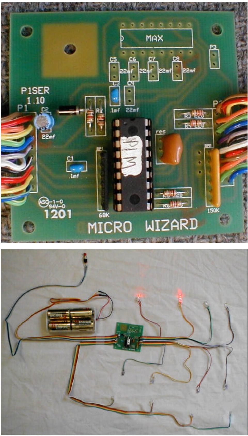
6 This is the circuit board in the enclosure we use for our timers The $40 P1 cheap kit with Serial Interface (Important! Be sure you are grounded before handling the microcontroller chip. Static electricity can damage it!) You can upgrade your P1 kit to the serial interface for an additional $15. The serial interface will permit your P1 to time races to one thousandth of a second and send the time to a computer or our remote time display unit (RTD). If you have the serial interface you can run race management software packages like Raceview, Grand Prix Race Manager, or DerbyMaster. The additional parts you get with Serial interface The P1 serial microcontroller MAX232 interface chip 5-10mf caps Female db-9 connector High bright test LED What is not included Cable or wire Disk or software (you can download some freeware at ftp.microwizard.com) Hard copy of the directions Hood for db-9 connector

7 Caution! Most of the 10mf caps face the same direction except for C4, which is reversed. Check on the back of the board when putting in the 10mf caps. The square hole is the one for the positive (longer) lead. This picture has a voltage regulator and headers, that you probably would not use when making yours. Troubleshooting To test the interface put the high bright LED into the db-9 socket. Connect the large positive side of the LED to pin 2 of the db-9 and connect the small negative side of the LED to pin 5 of the db-9. Now when you power-up the board the LED should be unlit. If the LED is lit then the LED may be plugged into the db-9 backwards or you may have some deeper problem. If the LED is off (like it should be) then trip each lane sensor while watching the LED. When the last sensor is tripped the LED will flash briefly and go out. The LED should flash once more when the start/reset switch is closed. If you get the LED to flash, then your serial interface is probably working. Plug the db-9 into a PC com port and run HyperTerminal program to display the times for your race. The data is sent out of our timer at 9600 baud, 8 data bits, 1 stop bit, no parity and no flow control. A HyperTerminal set-up file can be found on our FTP site.

PolyBot Board. User's Guide V1.11 9/20/08
 PolyBot Board User's Guide V1.11 9/20/08 PolyBot Board v1.1 16 pin LCD connector 4-pin SPI port (can be used as digital I/O) 10 Analog inputs +5V GND GND JP_PWR 3-pin logic power jumper (short top 2 pins
AXE114S BINARY CLOCK. revolution Revolution Education Ltd. Email: info@rev-ed.co.uk Web: www.rev-ed.co.uk Version 1.1 12/09/08 AXE114.PMD.
 AXE114S BINARY CLOCK Features: The PICAXE binary clock kit tells the time by lighting up blue LEDs in a binary pattern. This is a useful tool for teaching students binary code or simply just confusing/
User Guide Reflow Toaster Oven Controller
 User Guide Reflow Toaster Oven Controller Version 1.5-01/10/12 DROTEK Web shop: www.drotek.fr SOMMAIRE 1. Introduction... 3 2. Preparation of THE REFLOW CONTROLLER... 4 2.1. Power supply... 4 2.2. USB
TEECES DOME LIGHTING SYSTEMS
 This lighting system was designed by John V (Teeces) to be a simple, customizable, expandable and affordable solution for dome lighting. An Arduino micro-controller is used to tell LED driver chips which
ARDUINO SEVERINO SERIAL SINGLE SIDED VERSION 3 S3v3 (REVISION 2) USER MANUAL
 USER MANUAL") ARDUINO SEVERINO SERIAL SINGLE SIDED VERSION 3 S3v3 (REVISION 2) USER MANUAL X1: DE-9 serial connector Used to connect computer (or other devices) using RS-232 standard. Needs a serial cable, with at least
ARDUINO SEVERINO SERIAL SINGLE SIDED VERSION 3 S3v3 (REVISION 2) USER MANUAL X1: DE-9 serial connector Used to connect computer (or other devices) using RS-232 standard. Needs a serial cable, with at least
How to connect to a Class II router using a mobile-phone data cable specifically for Solwise & Safecom routers
 USB to router s serial port How to connect to a Class II router using a mobile-phone data cable specifically for Solwise & Safecom routers by Neo at RouterTech.Org Introduction Routers based on the AR7RD/AR7WRD
Analog control unit for mobile robots
 Analog control unit for mobile robots Soldering kit for experimentation For Fischertechnik robots and others Most diverse functions Requires no programming Patented sensor technology Summary We are pleased
BUILDING INSTRUCTIONS
 etap2hw 38 mm I2C to LCD Interface BUILDING INSTRUCTIONS October 2013 P. Verbruggen Rev 1.01 15-Oct-13 Page 1 Table of Contents Chapter 1 General Information 1.1 ESD Precautions 1.2 Further Supplies 1.3
Ocean Controls RC Servo Motor Controller
 Ocean Controls RC Servo Motor Controller RC Servo Motors: RC Servo motors are used in radio-controlled model cars and planes, robotics, special effects, test equipment and industrial automation. At the
AUTOMATIC CALL RECORDER JAMECO PART NO. 2163735
 AUTOMATIC CALL RECORDER JAMECO PART NO. 2163735 Experience Level: Intermediate Time Required: 1-2 Hours This project automatically records phone calls. The program, along with the adapter records each
RS232/DB9 An RS232 to TTL Level Converter
 RS232/DB9 An RS232 to TTL Level Converter The RS232/DB9 is designed to convert TTL level signals into RS232 level signals. This cable allows you to connect a TTL level device, such as the serial port on
RC2200DK Demonstration Kit User Manual
 Demonstration Kit User Manual Table of contents TABLE OF CONTENTS... 1 QUICK INTRODUCTION... 2 INTRODUCTION... 3 DEMONSTRATION BOARD... 4 POWER SUPPLY SECTION... 5 RS-232 INTERFACE... 6 CONNECTORS... 7
revolution Contents: Introduction Power 28-pin Project Board with input/output cables
 28-PIN IN IN PROJECT BOARD Contents: AXE020 28-pin Project Board with input/output cables Introduction The 28-pin project board is designed to allow rapid prototyping with 28-pin PICAXE microcontrollers.
Switch board datasheet EB007-00-1
 Switch board datasheet EB007-00-1 Contents 1. About this document... 2 2. General information... 3 3. Board layout... 4 4. Testing this product... 5 5. Circuit description... 6 Appendix 1 Circuit diagram
RN-WIFLY-EVAL-UM. WiFly Evaluation Kit. 2012 Roving Networks. All rights reserved. RN-WIFLY-EVAL-UM Version 1.32r 10/9/2012 USER MANUAL
 WiFly Evaluation Kit 2012 Roving Networks. All rights reserved. Version 1.32r 10/9/2012 USER MANUAL OVERVIEW This document describes the hardware and software setup for Roving Networks evaluation kits,
The Programming Interface
 : In-System Programming Features Program any AVR MCU In-System Reprogram both data Flash and parameter EEPROM memories Eliminate sockets Simple -wire SPI programming interface Introduction In-System programming
The CW Machine Hardware
 The CW Machine Hardware 2014 Ulrich H. Steinberg The CW Machine Hardware Version 2.2 1 Contents Introduction...3 Connecting the Hardware...4 The Configuration Switches...6 Power Considerations...8 Serial
CoolWave r 2 Phase Control Board and Cable Replacement Kits
 Instruction Sheet P/N 1102452A CoolWave r 2 Phase Control Board and Cable Replacement Kits Two kits are available to replace the CoolWave 2 phase control board: S S Phase Control Board and Cable Kit (required
Your Multimeter. The Arduino Uno 10/1/2012. Using Your Arduino, Breadboard and Multimeter. EAS 199A Fall 2012. Work in teams of two!
 Using Your Arduino, Breadboard and Multimeter Work in teams of two! EAS 199A Fall 2012 pincer clips good for working with breadboard wiring (push these onto probes) Your Multimeter probes leads Turn knob
GLOLAB Universal Telephone Hold
 GLOLAB Universal Telephone Hold 1 UNIVERSAL HOLD CIRCUIT If you have touch tone telephone service, you can now put a call on hold from any phone in the house, even from cordless phones and phones without
K128. USB PICmicro Programmer. DIY Electronics (HK) Ltd PO Box 88458, Sham Shui Po, Hong Kong. http://www.kitsrus.com mailto: peter@kitsrus.
 Ltd PO Box 88458, Sham Shui Po, Hong Kong. http://www.kitsrus.com mailto: peter@kitsrus.") K128 USB PICmicro Programmer DIY Electronics (HK) Ltd PO Box 88458, Sham Shui Po, Hong Kong http://www.kitsrus.com mailto: peter@kitsrus.com Last Modified March 31 2003 Board Construction The board is
K128 USB PICmicro Programmer DIY Electronics (HK) Ltd PO Box 88458, Sham Shui Po, Hong Kong http://www.kitsrus.com mailto: peter@kitsrus.com Last Modified March 31 2003 Board Construction The board is
Glolab Talking Phone Dial Monitor
 Introduction The detects the tones generated when numbers are dialed on your touch tone telephone and speaks the numbers that were dialed. This verifies that you dialed the correct number and is especially
Assembly Instructions: Shortwave Radio Kit
 Assembly Instructions: Shortwave Radio Kit MTM Scientific, Inc P.O. Box 522 Clinton, MI 49236 U.S.A Introduction Fig 1: The assembled Shortwave Radio Kit The SHORTWAVE RADIO KIT (#SWRAD) from MTM Scientific
Bluetooth HC-06 with serial port module Easy guide
 1 Bluetooth HC-06 with serial port module Easy guide This manual consists of 3 parts: PART 1. Overview of Bluetooth HC-06 module with serial port. PART 2. Installing Bluetooth HC-06 module with Bolt 18F2550
LG Air Conditioning Multi F(DX) Fault Codes Sheet. Multi Split Units
 Fault Codes Sheet. Multi Split Units") Multi Split Units If there is a fault on any LG Multi unit, an Error mark is indicated on the display window of the indoor unit, wired-remote controller, and LED s of outdoor unit control board. A two
Multi Split Units If there is a fault on any LG Multi unit, an Error mark is indicated on the display window of the indoor unit, wired-remote controller, and LED s of outdoor unit control board. A two
Total solder points: 167 Difficulty level: beginner 1 2 3 4 5 advanced DMX CONTROLLED RELAY K8072 ILLUSTRATED ASSEMBLY MANUAL
 Total solder points: 167 Difficulty level: beginner 1 2 3 4 5 advanced DMX CONTROLLED RELAY K8072 Control a relay by means of the wellknown DMX512 protocol. ILLUSTRATED ASSEMBLY MANUAL H8072IP-1 Features
SYSTEM 4C. C R H Electronics Design
 SYSTEM 4C C R H Electronics Design SYSTEM 4C All in one modular 4 axis CNC drive board By C R Harding Specifications Main PCB & Input PCB Available with up to 4 Axis X, Y, Z, A outputs. Independent 25
HARDWARE MANUAL. BrightSign HD120, HD220, HD1020. BrightSign, LLC. 16795 Lark Ave., Suite 200 Los Gatos, CA 95032 408-852-9263 www.brightsign.
 HARDWARE MANUAL BrightSign HD120, HD220, HD1020 BrightSign, LLC. 16795 Lark Ave., Suite 200 Los Gatos, CA 95032 408-852-9263 www.brightsign.biz TABLE OF CONTENTS OVERVIEW... 1 Block Diagram... 2 Ports...
Build A Video Switcher. Reprinted with permission from Electronics Now Magazine September 1997 issue
 Build A Video Switcher Reprinted with permission from Electronics Now Magazine September 1997 issue Copyright Gernsback Publications, Inc.,1997 BUILD A VIDEO SWITCHER FRANK MONTEGARI Watch several cameras
The definite Guide to Power connectors, Charging, and other Power related questions for the #11 Keychain Camera
 The definite Guide to Power connectors, Charging, and other Power related questions for the #11 Keychain Camera The same questions are being asked over and over again. I hope that this guide will clarify
M68EVB908QL4 Development Board for Motorola MC68HC908QL4
 M68EVB908QL4 Development Board for Motorola MC68HC908QL4! Axiom Manufacturing 2813 Industrial Lane Garland, TX 75041 Email: Sales@axman.com Web: http://www.axman.com! CONTENTS CAUTIONARY NOTES...3 TERMINOLOGY...3
Keep it Simple Timing
 Keep it Simple Timing Support... 1 Introduction... 2 Turn On and Go... 3 Start Clock for Orienteering... 3 Pre Start Clock for Orienteering... 3 Real Time / Finish Clock... 3 Timer Clock... 4 Configuring
!Operation:!1. Connect an external power source to J1 (+ and - IN terminals). The
. The") The CB500 Electronic Circuit Breaker is an resettable circuit breaker (fuse) that disconnects power when the trip setting is exceeded. There are 4 trip settings that can easily be changed and set during
The CB500 Electronic Circuit Breaker is an resettable circuit breaker (fuse) that disconnects power when the trip setting is exceeded. There are 4 trip settings that can easily be changed and set during
Assembly and User Guide
 1 Amp Adjustable Electronic Load 30V Max, 1 Amp, 20 Watts Powered by: 9V Battery Assembly and User Guide Pico Load is a convenient constant current load for testing batteries and power supplies. The digital
IP DSLAM IDL-2402. Quick Installation Guide
 IP DSLAM IDL-2402 Quick Installation Guide Table of Contents Package Contents... 3 Overview... 4 Setup the IDL series IP DSLAM... 5 Safety Instruction... 5 Hardware Installation... 6 WEB Configuration...
Tutorials Drawing a 555 timer circuit
 Step 1 of 10: Introduction This tutorial shows you how to make an electronic circuit using Livewire and PCB Wizard 3. You should follow this tutorial to learn the basic skills you will need to use Livewire
WHO ANSWERED FIRST? FIND OUT WITH THIS QUIZ BUZZER KIT
 WHO ANSWERED FIRST? FIND OUT WITH THIS QUIZ BUZZER KIT BUILD INSTRUCTIONS Before you put any components in the board or pick up the soldering iron, just take a look at the Printed Circuit Board (PCB).
Square D Clipsal DIN-Rail Four-Channel Auxiliary Input Unit
 Square D Clipsal DIN-Rail Four-Channel Auxiliary Input Unit SLCLE5504AUX for Use with Wired C-Bus Networks Instruction Bulletin Retain for future use. Square D Clipsal DIN-Rail Four-Channel Auxiliary Input
DS1307 Real Time Clock Breakout Board Kit
 DS1307 Real Time Clock Breakout Board Kit Created by Tyler Cooper Last updated on 2015-10-15 11:00:14 AM EDT Guide Contents Guide Contents Overview What is an RTC? Parts List Assembly Arduino Library Wiring
WIRING HARNESS FOR AS635P4. BLUE PLUG RED, BLUE, BLACK, WHITE - Plug in dual stage sensor harness
 WIRING HARNESS FOR AS635P4 ANTENNA NOT USED 5 PIN WHITE PLUG 2 PIN WHITE PLUG GREEN - PARKING BRAKE INPUT (-) BLUE - NOT USED 3 PIN BLUE PLUG RED, BLUE, BLACK, WHITE - Plug in dual stage sensor harness
Real Time Clock USB Evaluation Board V3.0
 Real Time Clock USB Evaluation Board V.0 Application Note February 9, 008 RTC EVB Intersil RTC Devices Supported Introduction This evaluation board provides a platform for testing Intersil Real Time Clock
Bluetooth + USB 16 Servo Controller [RKI-1005 & RKI-1205]
![Bluetooth + USB 16 Servo Controller [RKI-1005 & RKI-1205]](/thumbs/40/21161302.jpg "Bluetooth + USB 16 Servo Controller [RKI-1005 & RKI-1205]") Bluetooth + USB 16 Servo Controller [RKI-1005 & RKI-1205] Users Manual Robokits India info@robokits.co.in http://www.robokitsworld.com Page 1 Bluetooth + USB 16 Servo Controller is used to control up to
Bluetooth + USB 16 Servo Controller [RKI-1005 & RKI-1205] Users Manual Robokits India info@robokits.co.in http://www.robokitsworld.com Page 1 Bluetooth + USB 16 Servo Controller is used to control up to
LG Air Conditioning - Universal Split Fault Codes Sheet. Universal Split Systems
 Universal Split Systems If there is a fault on any LG Universal unit, a two digit number will appear on the remote controllers led display. If the unit does not have a remote controller the fault will
EDI Distributor Control Interface Wiring and Setup Instructions
 Universal I/O EDI Distributor Control Interface Wiring and Setup Instructions EDI UNIVERSAL I/O INTERFACE MODULE The only interface needed for EDI-V5 controls Network compatible with all older EDI controls
Troubleshooting Tips Lifestyle SA-2 & SA-3 Amplifier. Troubleshooting Tips
 Troubleshooting Tips Lifestyle SA-2 & SA-3 Amplifier Refer to the Lifestyle SA-2 & SA-3 Amplifier service manuals, part number 271720 for schematics, PCB layouts and parts lists. Preventative Repair Measures
Capacitive Touch Sensor Project:
 NOTE: This project does not include a complete parts list. In particular, the IC described here does not come in a dual-inline-package (DIP), and so a gull-wing package has to be soldered to an adaptor
Objectives: Part 1: Build a simple power supply. CS99S Laboratory 1
 CS99S Laboratory 1 Objectives: 1. Become familiar with the breadboard 2. Build a logic power supply 3. Use switches to make 1s and 0s 4. Use LEDs to observe 1s and 0s 5. Make a simple oscillator 6. Use
How To Power A Power Control On An Ip40 (Ipl) With A Power Supply (Iplug) With An Ip20 Controller (Iphones) With Power Control (Power Control) With No Antenna) With The Ip20 (Power)
 With A Power Supply (Iplug) With An Ip20 Controller (Iphones) With Power Control (Power Control) With No Antenna) With The Ip20 (Power)") MODEL NUMBER: ISC910-1-0-GB-XX ISC911-5-0-GB-XX IXP20 CONTROLLER SPECIFICATIONS Working Environment Plastic Housing... Power ImproX IXP20 Controller INSTALLATION MANUAL Designed to work in an indoor (dry)
MODEL NUMBER: ISC910-1-0-GB-XX ISC911-5-0-GB-XX IXP20 CONTROLLER SPECIFICATIONS Working Environment Plastic Housing... Power ImproX IXP20 Controller INSTALLATION MANUAL Designed to work in an indoor (dry)
Technical Specifications: The specifications represent a particular hardware platform. Application-specific software is provided.
 Preliminary TECHNICAL DATASHEET #TDAX020700 HYDRAULIC VALVE CONTROLLER 24 I/O 5 Analog and 6 Digital Inputs 1 Temperature Sensor and 1 RPM Sensor Interface 2 PWM Inputs 6 Proportional and 4 ON/OFF Current
Optical Sensor Interface for AFX Digital LED Timer/Counter by George Warner, Jan. 2003 warnergt@ptd.net
 Optical Sensor Interface for AFX Digital LED Timer/Counter by George Warner, Jan. 200 warnergt@ptd.net Abstract This paper presents a design for an optical sensor interface to an AFX Digital LED Timer/Counter.
ViZion Installation Guide
 ViZion Installation Guide v2.0 1 ViZion Installation Guide Table of Contents Inventory Hardware Setup Understanding Synchronization Cable Begin by taking an inventory of the required equipment DR Unit
Joule Thief 3.0 Kit. June 2012, Rev 1 1 http://www.easternvoltageresearch.com Joule Thief 3.0
 Kit Instruction Manual Eastern Voltage Research, LLC June 2012, Rev 1 1 http://www.easternvoltageresearch.com HIGH BRIGHTNESS LED THIS KIT USES A 1W CREE, HIGH BRIGHTNESS LED. DO NOT STARE AT THIS (OR
AC-PG-USBASP USBASP AVR Programmer
 AC-PG-USBASP-UG TABLE OF CONTENTS 1. OVERVIEW... 1 1.1. Introduction... 1 1.2. References... 1 1.2.1. Referenced Web Pages... 1 1.2.2. Acronyms and Abbreviations... 1 1.3. Supported Microcontrollers...
Model SETR-50 and SETR-51 Trim Tab Control
 Model SETR-50 and SETR-51 Trim Tab Control Pictured above is the SETR-50 with black switches on a gray background. The SETR-51 is identical except for the color, wherein it has black switches on a black
C220 PRELIMINARY TUBE PREAMPLIFIER SERVICE MANUAL. SERIAL NO. WS1001 And Above C220. Serial Number W S1001 And Above CONTENTS
 Performance Specifications... 2 Notes... 2 Rear Panel... 3 Section Location... 3 Block Diagram... 5-6 Interconnection Diagram... 7-8 Main Schematic and PCB... 9-18 C220 TUBE PREAMPLIFIER CONTENTS Display
TX GSM SMS Auto-dial Alarm System. Installation and User Manual
 TX GSM SMS Auto-dial Alarm System Installation and User Manual Product Features: 1. 16 wireless zones, 3 wired zones alarm system, suitable for small to medium size offices and homes. 2. The system uses
Animated Lighting Software Overview
 Animated Lighting Software Revision 1.0 August 29, 2003 Table of Contents SOFTWARE OVERVIEW 1) Dasher Pro and Animation Director overviews 2) Installing the software 3) Help 4) Configuring the software
Massachusetts Institute of Technology Department of Electrical Engineering and Computer Science 6.115 Microprocessor Project Laboratory
 Massachusetts Institute of Technology Department of Electrical Engineering and Computer Science 6.115 Microprocessor Project Laboratory Connecting your PSoC Evaluation Board It is easy and fun to avoid
PRO PLM Installation Instructions
 PRO PLM Installation Instructions PROFESSIONAL INSTALLATION STRONGLY RECOMMENDED Installation Precautions: Roll down window to avoid locking keys in vehicle during installation Avoid mounting components
Installation & Operation Manual
 DRAFT Installation & Operation Manual Embedded Power Supply Monitoring Transponder For XM2 Power Supplies Phoenix Broadband Technologies, LLC. Revision History Release Date Revision Description Rev 1 10/19/06
Revision Date: September 19, 2006
 RS232 to TTL Cables Revision Date: September 19, 2006 SuperDroid Robots Inc. is incorporated in Wake County, NC USA SuperDroid Robots also does business as Team Half-Life SuperDroid Robots is a registered
Hardware Connections between Arduino and IMU Nori Wilkins Apr. 5, 2013
 Hardware Connections between Arduino and IMU Nori Wilkins Apr. 5, 2013 Abstract Sensors are commonly used throughout many world wide applications. Out of many sensors that are used, the inertial measurement
Programming the On-Chip Flash on a phycore-xc161 phycore-xc167
 Application Note Programming the On-Chip Flash on a phycore-xc161 phycore-xc167 Application Note Edition July 2003 LAN-020e_1 Application Note Preface...1 1 Installing Infineon MemTool...2 2 Preparing
3 Slot Payphone Controller
 5A2 3 Slot Payphone Controller The 3 Slot Payphone -- Part of American History Building a Coin Relay Controller Version S1BX Instruction Manual and Safety Precautions It is very important that for your
Alpha 10 SERVICE MANUAL. Downloaded from www.cbradio.nl. MAX 10 Meter Amateur Transceiver AM/FM/CW/SSB 6 BAND PROGRAMMABLE MODEL AM-1000.
 Alpha 10 MAX 10 Meter Amateur Transceiver MODEL AM-1000 AM/FM/CW/SSB 6 BAND PROGRAMMABLE SERVICE MANUAL Downloaded from www.cbradio.nl Cover Page LOUDER TALKBACK MOD Alpha 10 Max - Model AM-1000 4.7K Resistor
DET Practical Electronics (Intermediate 1)
") DET Practical Electronics (Intermediate 1) 731 August 2000 HIGHER STILL DET Practical Electronics (Intermediate 1) Support Materials CONTENTS Section 1 Learning about Resistors Section 2 Learning about
DET Practical Electronics (Intermediate 1) 731 August 2000 HIGHER STILL DET Practical Electronics (Intermediate 1) Support Materials CONTENTS Section 1 Learning about Resistors Section 2 Learning about
OPERATING INSTRUCTIONS Model ST-888 DTMF ANI/ENI Display Decoder
 P R O D U C T G R O U P OPERATING INSTRUCTIONS Model ST-888 DTMF ANI/ENI Display Decoder Manual # 600-0901 November 30, 1999 Rev. D - 99068 DESCRIPTION The ST-888 Mobilecall Display Decoder is a desktop
ezsystem elab16m Project 1F: Alarm System (Full Project description)
") ezsystem elab16m Project 1F: Alarm System (Full Project description) ezsystem The aim of ezsystem is to enable Creativity and Innovation at an early age in a Problem Based Learning (PBL) approach. ezsystem
ezsystem elab16m Project 1F: Alarm System (Full Project description) ezsystem The aim of ezsystem is to enable Creativity and Innovation at an early age in a Problem Based Learning (PBL) approach. ezsystem
AXE033 SERIAL/I2C LCD
 AXE033 SERIAL/I2C LCD The serial LCD and clock module allows microcontroller systems (e.g. PICAXE) to visually output user instructions or readings, without the need for a computer. This is especially
i ChatterBox! Motorcycle Security
 i Before you Start the Installation * Please read this manual to become familiar with the requirements necessary to complete the installation. * Use a high quality multi-meter to test all wires before
Microstep Driver Manual Version 6/13/2006
 Microstep Driver Manual Version 6/13/2006 Embedded Acquisition Systems 2517 Cobden Street Sterling Heights, MI 48310 http://www.embeddedtronics.com email sales@embeddedtronics.com copyright 2003-2004 EAS
The ACD pro replaces any resistance based controller and is suitable for nearly any motor within the current rating.
 1. Main Features Non contact trigger. Minimal maintenance. Microcontroller- based PWM control. New braking behavior and high acceleration. Adjustable brake sensitivity and choke. Suitable for all motors
Scorpius Installation Guide Version 1.7
 Scorpius Installation Guide Version 1.7 Updates on yellow since Version 1.5 Updates on green since Version 1.6 CONTROLLER Install 2 x AAA batteries by removing casing and knob screws. Ensure polarity is
Cable Connection Procedures for Cisco 1900 Series Routers
 CHAPTER 5 Cable Connection Procedures for Cisco 1900 Series Routers This document describes how to connect your Cisco 1941 integrated services router to a power source and to networks and external devices.
How to read this guide
 How to read this guide The following shows the symbols used in this Quick start guide with descriptions and examples. Symbol Description Example P oint Reference Caution [ ] This symbol explains information
Battery Charger For Nickel Cadmium and Nickel-Metal Hydride Rechargeable Batteries Model PSN Series
 Battery Charger For Nickel Cadmium and Nickel-Metal Hydride Rechargeable Batteries Model PSN Series Operating Instructions WARNING CONCERNING THE REMOVAL OF COVER: CAUTION: TO PREVENT THE RISK OF ELECTRIC
HCS-3300/3302/3304 USB Remote Programmable Laboratory Grade Switching Mode Power Supply
 1. INTRODUCTION HCS-3300/3302/3304 USB Remote Programmable Laboratory Grade Switching Mode Power Supply User Manual This family of efficient, upgraded SMPS with small form factor, auto cross over CV CC,
EVAL-UFDC-1/UFDC-1M-16
 Evaluation Board for Universal Frequency-to- Digital Converters UFDC-1 and UFDC-1M-16 EVAL-UFDC-1/UFDC-1M-16 FEATURES Full-Featured Evaluation Board for the Universal Frequency-to-Digital Converters UFDC-1
Advanced LED Controller (LED Chaser)
") Advanced LED Controller (LED Chaser) Introduction. Advanced LED controller (also known as LED Chaser) is microcontroller based circuit designed to produce various visual LED light effects by controlling
Advanced LED Controller (LED Chaser) Introduction. Advanced LED controller (also known as LED Chaser) is microcontroller based circuit designed to produce various visual LED light effects by controlling
Constructing a precision SWR meter and antenna analyzer. Mike Brink HNF, Design Technologist.
 Constructing a precision SWR meter and antenna analyzer. Mike Brink HNF, Design Technologist. Abstract. I have been asked to put together a detailed article on a SWR meter. In this article I will deal
 P105 SINGLE STICK REVERSER PICTURE 1: PCB with headers PICTURE 3: Resistors added PICTURE 5: Add tactile switch (button) PICTURE 7: Fit lead and PIC chip. NOTE! ANTI-STATIC PRECAUTIONS REQUIRED PICTURE
Lab Experiment 1: The LPC 2148 Education Board
 Lab Experiment 1: The LPC 2148 Education Board 1 Introduction The aim of this course ECE 425L is to help you understand and utilize the functionalities of ARM7TDMI LPC2148 microcontroller. To do that,
TEACHING RESOURCES SCHEMES OF WORK DEVELOPING A SPECIFICATION COMPONENT FACTSHEETS HOW TO SOLDER GUIDE GET IN TUNE WITH THIS FM RADIO KIT. Version 2.
 TEACHING RESOURCES SCHEMES OF WORK DEVELOPING A SPECIFICATION COMPONENT FACTSHEETS HOW TO SOLDER GUIDE GET IN TUNE WITH THIS FM RADIO KIT Version 2.0 Index of Sheets TEACHING RESOURCES Index of Sheets
REPAIRING ROWE/AMI R84 - R88
 REPAIRING ROWE/AMI R84 - R88 CENTRAL CONTROL COMPUTERS Using The Jukebox Troubleshooter... Comes with two 20-pin strip headers and PC serial cable Uses a PC serial port for interactive control Full memory
Business/Home GSM Alarm System. Installation and User Manual
 Business/Home GSM Alarm System Installation and User Manual Brief Introduction: GSM 900/1800/1900 bands, can be used in most parts of the world Full duplex communication with the host Monitor the scene
Lab 3 - DC Circuits and Ohm s Law
 Lab 3 DC Circuits and Ohm s Law L3-1 Name Date Partners Lab 3 - DC Circuits and Ohm s Law OBJECTIES To learn to apply the concept of potential difference (voltage) to explain the action of a battery in
Daikin Magnitude TM Chiller Unit Controller BACnet Communication Module (MS/TP, IP, Ethernet)
") Installation and Maintenance Manual IM 963-1 Group: Controls Part Number: IM 963 Date: July 2010 Supercedes: IM 963 Daikin Magnitude TM Chiller Unit Controller BACnet Communication Module (MS/TP, IP, Ethernet)
Installation and Maintenance Manual IM 963-1 Group: Controls Part Number: IM 963 Date: July 2010 Supercedes: IM 963 Daikin Magnitude TM Chiller Unit Controller BACnet Communication Module (MS/TP, IP, Ethernet)
K9 Heat Alarm Owners Manual HA-1520
 K9 Heat Alarm Owners Manual HA-1520 Your K9 Heat Alarm is a state of the art product designed and developed by ACEK9.COM a division of Radiotronics, Inc. It is a unique blend of positive features taken
INTRODUCTION TO SERIAL ARM
 INTRODUCTION TO SERIAL ARM A robot manipulator consists of links connected by joints. The links of the manipulator can be considered to form a kinematic chain. The business end of the kinematic chain of
Micrio WS1 Replacement Wind Speed Sensor and WC1 Replacement Wind Compass Sensor for Raymarine ST50 and ST60 Wind Instruments. Rev 4.
 Micrio WS1 Replacement Wind Speed Sensor and WC1 Replacement Wind Compass Sensor for Raymarine ST50 and ST60 Wind Instruments. Rev 4.1 The Micrio WS1 Wind Speed Sensor and WC1 Compass Sensor are direct
Scorpius Installation Guide Version 2.1
 Scorpius Installation Guide Version 2.1 CONTROLLER Install 2 x AAA batteries by removing casing and knob screws. Ensure polarity is correct. Reinstall screws. Battery life approx. 3 months of average use.
INSTALLATION GUIDE. www.security.soundstream.com FCC ID NOTICE
 AL.1 AUTO SECURITY SYSTEM INSTALLATION GUIDE www.security.soundstream.com FCC ID NOTICE This device complies with Part 15 of the FCC rules. Operation is subject to the following conditions: 1. This device
K8025 VIDEO PATTERN GENERATOR. Check the picture quality of your monitor or TV, ideal for adjustment or troubleshooting.
 K8025 ILLUSTRATED ASSEMBLY MANUAL H8025IP 1 VIDEO PATTERN GENERATOR Check the picture quality of your monitor or TV, ideal for adjustment or troubleshooting. Forum Participate our Velleman Projects Forum
BrightSign Expander Hardware Guide
 Hardware Guide PCBA: Rev C Version: 0.1 Saratoga, CA, USA 1 Table of Contents OVERVIEW... 3 EXPANDER BLOCK DIAGRAM... 4 PORTS... 6 POWER CONNECTOR... 6 OPTICAL SPDIF CONNECTOR... 6 DB25 SWITCH/LED CONNECTOR...
TS1 Ultra Sonic Tank Sender Training. 27 November 2007
 1 TS1 Ultra Sonic Tank Sender Training 27 November 2007 2 Topics TS1 Tank Sender TS1-PK Programming Kit TS1 Programming Software Programming TS1 Troubleshooting 3 TS1 TS1 is an advanced tank sender based
OEM Manual MODEL 2350 ELECTRONIC DUAL CYLINDER SCALE
 OEM Manual MODEL 2350 ELECTRONIC DUAL CYLINDER SCALE Scaletron Industries, Ltd. Bedminster Industrial Park 53 Apple Tree Lane P.O. Box 365 Plumsteadville, PA 18949 USA Toll Free: 1-800-257-5911 (USA &
INSTALLATION MANUAL 3RP / 5RP 4-BUTTON SERIES VEHICLE SECURITY SYSTEMS
 3RP / 5RP 4-BUTTON SERIES VEHICLE SECURITY SYSTEMS INSTALLATION MANUAL Before you begin the installation Read the INSTRUCTIONS! Always use a multi-meter when verifying vehicle wiring. Before mounting the
IMMS-CCC. IMMS-CCC Hardwire Central Interface. Installation Instructions
 IMMS-CCC IMMS-CCC Hardwire Central Interface Installation Instructions TABLE OF CONTENTS... Choose a Location... 1 Connections... 2 Operations... 3 Software Configuration... 4 Troubleshooting... 5 Loopback
The Child Reminder System Installation Manual
 The Child Reminder System Installation Manual Revised June, 2006 Detailed installation information can be found at www.childreminder.com. Get through your installation quickly and easily by calling 1-888-330-6786