WEB log. Device connection plans
|
|
|
- Tobias Chase
- 8 years ago
- Views:
Transcription
1 WEB log LIGHT+ 20 BASIC 100 PRO unlimited Device connection plans Version *

2 Copyright Copyright for this manual remains with the manufacturer. No part of this manual may be reproduced or edited, duplicated or distributed using electronic systems, without written permission. Compensation shall be payable in the event of any copyright infringements. All brand names mentioned in this manual are the property of their respective manufacturers and are hereby acknowledged. Details regarding the manual The original document is written in German. All other language versions are translations of the original document and are hereby identified as such. All information in this operating manual has been compiled and checked with the greatest care and diligence. Nevertheless, the possibility of errors cannot be entirely excluded. The manufacturer therefore cannot accept any liability for errors or their consequences. Subject to technical alterations. *Current version The latest version of this document "Device connection plans" can be found on the manufacturer's website.

3 Contents 1. Notes on this operating manual Safety instructions for operation Intended use Personnel Overview of interfaces Cabling RS485 and RS232/ Sensors Irradiance sensors Pyranometer Temperature sensors Hygro-thermal sensors Wind speed sensors Wind direction sensors Weather stations Power quality analyzers Janitza power quality analyzers Energy meter Three-phase energy meter String measuring technology meteocontrol string measuring technology

4 1. Notes on this operating manual This manual is a key aid when it comes to ensuring proper operation of the device. It contains important information and safety notes to help you use the devices correctly, economically and in the intended manner. The manual helps to avoid dangers, to reduce repair costs and downtimes, and to increase the reliability and operating life of the devices. During installation, all the manuals for system modules and components must be taken into account. 2. Safety instructions for operation 2.1 Intended use Only the permitted signals and signal strengths may be applied to the connections of the data loggers and modules used here. Installation is only permitted indoors. For installation outdoors or in a dusty environment, the device must be installed in a standardized protective enclosure. 2.2 Personnel Installation, commissioning and maintenance of the device may only be performed by a qualified electrician. Given their specialist training, knowledge, experience and familiarity with the relevant standards and regulations, a qualified electrician is in a position not only to carry out work on electrical systems but also to recognize and avoid possible dangers unaided. The qualified electrician must comply with the occupational health and safety laws in force. Please note in particular: all national installation and set-up regulations (e.g. VDE in Germany), all generally accepted codes of practice, information on transport, installation, operation, service, maintenance and disposal given in the documentation for the devices used, specific values, limits and information relating to operating and ambient conditions on type plates and in data sheets. 2 48

5 3. Overview of interfaces Overview of interfaces (1) Analog inputs (DI1 DI4) (7) Ethernet (2) Reset button (8) RS485 (3) Digital inputs (DI1 DI4) (9) RS232/422 (4) Power supply (10) Digital output (DO1) (110 V 230 V AC) (5) RJ45 phone socket (PSTN) (11) Switch between RS232 / RS422 (6) Power supply (24 V DC) Can also be operated as RS485 for additional Modbus devices 3 48
 Power supply (24 V DC) Can also be operated as RS485 for additional Modbus")
6 4. Cabling 4.1 RS485 and RS232/422 The two RS485 and RS232/422 interfaces are used to query information recorded on various bus devices such as inverters, power quality analyzers, etc. The RS232/422 interface can also be used as an RS485 interface. In order to do this the interface has to be operated in RS422 mode (for this, please refer to the manual of your WEB log data logger). Which interface you should use to connect inverters and accessories depends on your specific driver. Please refer to the appropriate driver datasheet ( Please note the following regarding the bus cabling: All devices on a bus must use the same protocol to communicate. The data logger functions exclusively as a master on the bus. The maximum permitted number of bus devices has to be observed (see driver datasheets). The order of the bus devices on the bus is unimportant. The use of a repeater is necessary for every 32nd bus device and for long cable runs. The bus should be cabled with a twisted and shielded pair of wires. The shield of the bus cable must be grounded at one end of the connection only. The data logger does not have its own grounding When you wire the bus wires, make sure that AC and DC cables are routed separately. Do not switch the buses signal wires. Different manufacturers interpret the RS485 interface s underlying standard differently. A and B wire labels may be different for different manufacturers. The + and indicators, on the other hand, are unambiguous. To prevent reflections, the bus must always be terminated with a parallel terminator. 4 48

7 Daisy chain If you want to connect more than one device to the bus, you must daisychain the connection. This means that different devices can only be queried jointly if they use the same communication protocol and the same serial communication parameters (baud rate, data bits, parity, stop bits). The first and last device on the bus must be terminated with a resistor. The data logger is provided with integrated terminating resistors that are permanently activated. Daisy chain cabling RS485/

8 Star wiring Another possible way of operating multiple devices on the RS485 bus is called star wiring. In this wiring variant, a HUB 6 Port RS485 S (item number ) is used to seperate the bus into a serveral bus strings. To connect the HUB 6 Port RS485 S to the WEB log, please use a Connect Universal RS cable (item number: ). Various devices can only be queried together if they communicate with the same protocol and have identical serial communication parameters (baud rate, number of data bits, parity, stop bits). Each bus string can have a maximum length of 1200 m. All the devices on the same bus string are wired together in a daisy chain. The first and last device of each bus string must be terminated with a resistor. The HUB has integrated terminating resistors at each interface, which are permanently activated. In this wiring variant, the total number of bus devices may not exceed the maximum permissible number of bus devices. Star wiring for RS

9 7 48

10 5. Sensors 5.1 Irradiance sensors SI-12-TC, SI-12-TC-T Connection Wire color Use Black Ground Red Power supply (12 24 V DC) Brown Temperature signal (0 10 V / 0 20 ma / ma) Orange Irradiance signal (0 10 V) Configuration data SI-12-TC-T Sensor Measurement Input Unit Gradient Offset Irradiance Analog 0 10 V W/m Temperature Analog 0 10 V C In the case of the sensor SI-12-TC, the brown wire for temperature measurement is not used 8 48
 Orange Irradiance signal (0 10 V) Configuration data SI-12-TC-T Sensor Measurement Input Unit Gradient")
11 Sensor connection 9 48

12 SI-12-TC-LC Connection Wire color Use Black Ground Red Power supply (12 24 V DC) Orange Irradiance signal (0 10 V) Configuration data Sensor Measurement Input Unit Gradient Offset SI-12-TC-T Irradiance Analog 0 10 V W/m

13 Sensor connection 11 48

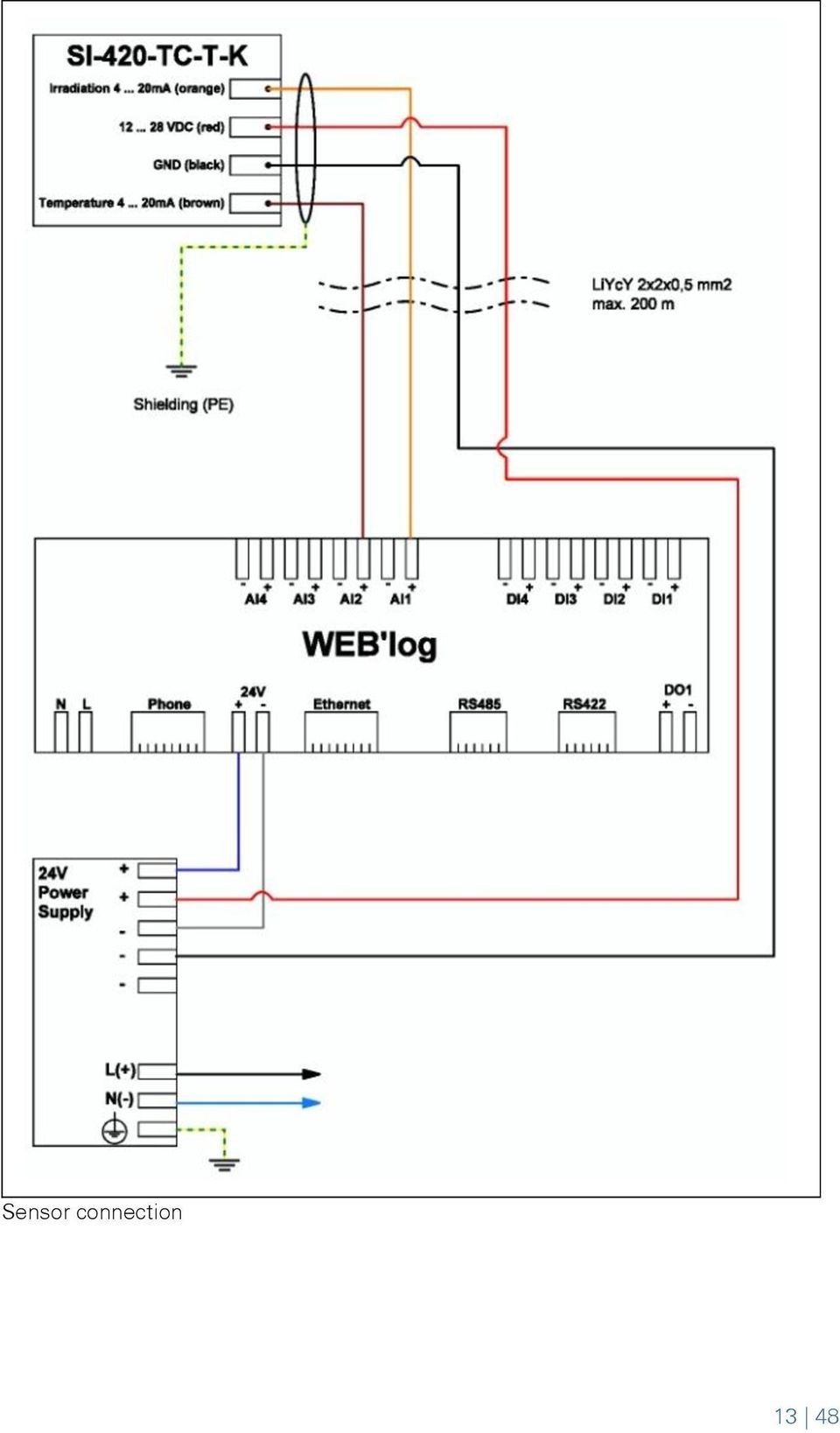
14 SI-420-TC, SI-420-TC-T Connection Wire color Use Black Ground Red Power supply (12 24 V DC) Brown Temperature signal ( ma) Orange Irradiance signal (4 20 ma) Configuration data Sensor Measurement Input Unit Gradient Offset Irradiance Analog 4 20 ma W/m SI-420-TC-T Temperature Analog ma C In the case of the sensor SI-420-TC, the brown wire for temperature measurement is not used 12 48

15 Sensor connection 13 48
16 Si-RS485-TC-T (Modbus RTU) Connection Wire color Use Black Ground Red Power supply (12 24 V DC) Brown RS485 Modbus interface A (+) Orange RS485 Modbus interface B (-) Set the bus address on the sensor (see sensor documentation). If the device is the last one on the RS485 bus, terminate the bus with a 120 Ω terminating resistor. Various Modbus devices can only be queried together if the serial communication parameters are identical (baud rate, number of data bits, parity, stop bits)

17 Sensor connection 15 48

18 Si-RS485-TC-T V2 (Modbus RTU) Connection Wire color Use Black Ground Red Power supply (12 24 V DC) Brown RS485 Modbus interface A (+) Orange RS485 Modbus interface B (-) Set the bus address on the sensor (see sensor documentation). If the device is the last one on the RS485 bus, terminate the bus with a 120 Ω terminating resistor. Various Modbus devices can only be queried together if the serial communication parameters are identical (baud rate, number of data bits, parity, stop bits)

19 Sensor connection 17 48

20 5.2 Pyranometer Kipp & Zonen SMP10 / SMP11 (analog interface) Connection Wire color Black White Brown Green Use Ground Power supply (5 30 V DC) Irradiance signal GND Irradiance signal (4 20 ma) Configuration data Measurement Input Unit Gradient Offset Irradiance on horizontal plane Analog 4 20 ma W/m Irradiance on module plane Analog 4 20 ma W/m The sensor outputs (power signal) must have a resistance of approx. 500 Ω for a correct measurement. Since the data logger has an internal load resistance of 70 Ω, we recommend you to install a commonly available 430 Ω load resistor on the sensor output. Pyranometers can be used to measure irradiance either on the horizontal plane or on the module plane

21 Sensor connection 19 48
22 Kipp & Zonen SMP10 / SMP11 (Modbus RTU) Connection Wire color Use Black Ground White Power supply (5 30 V DC) Gray RS485 Modbus interface B (-) Yellow RS485 Modbus interface A (+) Blue RS485 Modbus interface GND Set the bus address on the sensor (see sensor documentation). If the device is the last one on the RS485 bus, terminate the bus with a 120 Ω terminating resistor. Various Modbus devices can only be queried together if the serial communication parameters are identical (baud rate, number of data bits, parity, stop bits). Pyranometers can be used to measure irradiance either on the horizontal plane or on the module plane
23 Sensor connection 21 48
24 Kipp & Zonen CMP11 with AMPBOX Connection Wire color Use Blue Power supply + 24 V DC Yellow Analog output 4 ma to 20 ma Configuration data Measurement Input Unit Gradient Offset Irradiance on horizontal plane Analog 4 20 ma W/m Irradiance on module plane Analog 4 20 ma W/m Pyranometers can be used to measure irradiance either on the horizontal plane or on the module plane. The input and output of the AMPBOX are galvanically isolated to prevent feedback and interference and to protect the data logger. The connecting cable between the AMPBOX and the pyranometer must not be lengthened or shortened. Because the AMPBOX and the pyranometer are calibrated together, both devices must always be installed together
25 Sensor connection 23 48
26 5.3 Temperature sensors PT1000 Adhesive Sensor Connection Wire color Brown White Use Ground PT1000 temperature signal Configuration data Measurement Input Unit Gradient Offset Temperature PT1000 C
27 Sensor connection 25 48
28 PT100 adhesive sensor with signal converter Connection Wire color Use Red Ground White Temperature signal PT100 Configuration data Measurement Input Unit Gradient Offset Temperature Analog 0 10 V C The following signal converters are available for connecting the temperature sensor: PT100 Signal converter 24 V power supply PT100 Signal converter 230 V power supply 26 48
29 Sensor connection 27 48
30 5.4 Hygro-thermal sensors meteocontrol compact hygro-thermal sensor Connection Wire color Yellow Black Green Brown Use Power supply for humidity sensor (24 V DC) Power supply for temperature sensor (24 V DC) Temperature signal (4 20 ma) Ambient humidity signal (4 20 ma) Configuration data Measurement Input Unit Gradient Offset Temperature Analog 4 20 ma C Relative humidity Analog 4 20 ma % r. h The sensor outputs (power signal) must have a resistance of approx. 500 Ω for a correct measurement. Since the data logger has an internal load resistance of 70 Ω, we recommend you to install commonly available 430 Ω load resistors on the sensor outputs
31 Sensor connection 29 48
32 5.5 Wind speed sensors meteocontrol compact wind speed sensor (0 10 V) / (4 20 ma) Connection Wire color Use Yellow Wind speed signal ground Green Wind speed signal (4 20 ma) Gray Power supply for heater (24 V AC or DC +) Pink Heater GND (24 V DC -) White Power supply for sensor (24 V AC or DC +) Brown Sensor GND (24 V AC or DC -) Configuration data Sensor Measurement Input Unit Gradient Offset mc comp. wind speed sensor (0-10 V) Wind speed Analog 0 10 V m/s 5 0 mc comp. wind speed sensor (4-20 ma) Wind speed Analog 4 20 ma m/s
33 Sensor connection 31 48
34 5.6 Wind direction sensors meteocontrol compact wind direction sensor (0 10 V) / (4 20 ma) Connection Wire color Use Yellow Wind direction signal GND Green Wind direction signal (4 20 ma) Gray Power supply for heater (24 V AC or DC +) Pink Heater GND (24 V DC -) White Power supply for sensor (24 V AC or DC +) Brown Sensor GND (24 V AC or DC -) Configuration data Sensor Measurement Input Unit Gradient Offset mc compact wind direction (0-10 V) Wind direction Analog 0 10 V 36 0 mc compact wind direction (4-20 ma) Wind direction Analog 4 20 ma
35 Sensor connection 33 48
36 5.7 Weather stations Compact weather station WS501 / WS510 / WS600 UMB (Modbus RTU) Connection Wire color Use Yellow RS485 bus wire A (+) Green RS485 bus wire B (-) Brown Power supply for sensor (+24 V DC) White Sensor GND (-) Red Power supply for heater (+24 V DC) Blue Heater GND (-) Set the bus address on the compact weather station (see compact weather station documentation). If the device is the last one on the RS485 bus, terminate the bus with a 120 Ω terminating resistor. Various Modbus devices can only be queried together if the serial communication parameters are identical (baud rate, number of data bits, parity, stop bits)
37 Sensor connection 35 48
38 6. Power quality analyzers 6.1 Janitza power quality analyzers UMG604 (Modbus RTU) Set the bus address on the power quality analyzer (see power quality analyzer documentation). If the device is the last one on the RS485 bus, terminate the bus with a 120 Ω terminating resistor. To ensure sufficient query speed for the power control, it is recommended to operate the power quality analyzer as a single device on the bus
39 Sensor connection 37 48
40 7. Energy meter 7.1 Three-phase energy meter ALE3 (Modbus RTU) energy meter Set the bus address on the energy meter (see energy meter documentation). If the device is the last one on the RS485 bus, terminate the bus with a 120 Ω terminating resistor. Energy meter suitable for IPL function 38 48
41 Sensor connection 39 48
42 Energy meter ALE3 (S0) Pulse value of the S0 interface is 1000 pul/kwh Energy meter suitable for IPL function Configuring the IPL meter In the factory, the meter s S0 interface is set up in a way that allows for pulses to be transmitted in both directions (in and out), when energy is flowing. With this setting it is not possible to determine the direction of flow. To use the meter for IPL you will need to configure the S0 interface for one energy flow direction. You will need to make the following settings, depending on the recorded measurement. Measurement Use Setting Energy fed into the grid Feed-in meter Out mode Energy drawn from the grid Import meter In mode Energy used by electrical equipment Consumption meter In mode 40 48
43 Sensor connection 41 48
44 8. String measuring technology 8.1 meteocontrol string measuring technology i catcher 8-1B, i catcher 16-1B, i catcher 24-1B (Modbus RTU) Set the bus address on the i'catcher (see i'catcher documentation). If this is the last bus device on the RS485 bus, set the terminating switches (Term.) to On. Various Modbus devices can only be queried together if the serial communication parameters are identical (baud rate, number of data bits, parity, stop bits)
45 (1) RJ12 connector (WEB'log), (5) Last i catcher RS485/RS422 (2) Pinout of Connect Universal RS (6) Terminating resistor 120 Ω (3) Terminals (i catcher) (7) Bus cable (4) First i catcher 43 48
46 Connection i catcher, central power supply, separate shield Connection i catcher, central power supply, connected shield 44 48
47 Connection i catcher, decentralized power supply, separate shield Connection i catcher decentralized power supply, connected shield 45 48
48 46 48
49 47 48
50 48 48
51
52 Text and illustrations represent state-of-the-art technology at the time of printing Subject to technical modifications We assume no liability for printing errors. Version
WEB log. Device connection plans
 WEB log LIGHT+ 20 BASIC 100 PRO unlimited Device connection plans Version 20160425* Copyright Copyright for this manual remains with the manufacturer. No part of this manual may be reproduced or edited,
* DISCLAIMER: Contents. How to Use This Guide: COMMERCIAL INSTALL GUIDE 2
 COMMERCIAL INSTALL GUIDE 2 Contents How to Use This Guide: The first section of this guide is designed to assist you with the installation of your DECK Monitoring hardware. The revenue grade meter and
Technical Information POWER PLANT CONTROLLER
 Technical Information POWER PLANT CONTROLLER Content The Power Plant Controller offers intelligent and flexible solutions for the control of all PV power plants in the megawatt range. It is suitable for
Application/Connection Examples
 This Quick Start Guide is designed to familiarize the user with the connection and configuration of the DTS-305 DIN rail mounted single / 3 phase power & energy meter with RS-485 or TCP communications.
SmartLogger1000. Quick Installation Guide. Issue 05. Date 2013-12-15 HUAWEI TECHNOLOGIES CO., LTD.
 Issue 05 Date 2013-12-15 HUAWEI TECHNOLOGIES CO., LTD. 2013. All rights reserved. No part of this document may be reproduced or transmitted in any form or by any means without prior written consent of
Data Bulletin. Communications Wiring for POWERLINK G3 Systems Class 1210 ABOUT THIS BULLETIN APPLICATION INTRODUCTION.
 Data Bulletin 1210DB0002R3/05 03/2005 LaVergne, TN, USA Communications Wiring for POWERLINK G3 Systems Class 1210 Retain for future use. ABOUT THIS BULLETIN This data bulletin describes the proper wiring
Table of Contents. Creating a VC1000 Network... 3
 2 Table of Contents Creating a VC1000 Network... 3 Topology... 3 Unit ddressing... 4 Terminating Resistors... 5 Shielding... 5 Interconnecting the common... 6 ias Resistors... 6 VC1000 Hardware Configuration...
Installation Guide Solar Connect-11
 Installation Guide Solar Connect-11 Version 1.1 Contents Important Product Information 3 System Registration Form 4 Solar Connect-11 Overview 5 Internet & Power Connections 6 Single Phase CT Connections
Power Supply and Cabling Options. SmartTrak 100/101/140
 Power Supply and Cabling Options SmartTrak 00/0/40 2 Power Supply and Cabling Options SmartTrak 00/0/40 Table of Contents Power Supplies... Communication Cables... Accessory Options... Appendix A Communication
DAM Series DAM124 4DIN+8AI+4DO Module Model No.:DAM124 WebSite: www.gsm-m2m.com
 DAM Series DAM124 4DIN+8AI+4DO Module Model No.:DAM124 WebSite: www.gsm-m2m.com This handbook has been designed as a guide to the installation and operation of King Pigeon Hi-Tech.Co.,Ltd DAM series. Statements
User Manual Revision 1.400 English Converter / Adapter Ethernet to RS232 / RS485 (Order Code: HD67038-2 HD67038-2-M HD67038-25 HD67038-25-M)
") Document code: MN67038-2_ENG Revision 1.400 Page 1 of 25 User Manual Revision 1.400 English Converter / Adapter Ethernet to RS232 / RS485 (Order Code: HD67038-2 HD67038-2-M HD67038-25 HD67038-25-M) for
Document code: MN67038-2_ENG Revision 1.400 Page 1 of 25 User Manual Revision 1.400 English Converter / Adapter Ethernet to RS232 / RS485 (Order Code: HD67038-2 HD67038-2-M HD67038-25 HD67038-25-M) for
Temp. & humidity Transmitter Instructions
 Temp. & humidity Transmitter Instructions AQ3485/AQ3485Y www.aosong.com 1 Product Overview AQ3485/ AQ3485Y outdoor network temperature and humidity transmitter is accurate measurement of relative humidity
SOLARCARE SERIES PRODUCT AND APPLICATION GUIDE
 SOLARCARE SERIES PRODUCT AND APPLICATION GUIDE for solar energy management LEATEC Delivering Solutions for Energy Management SOLAR ENERGY DATA CENTER BUILDING 4 to8 String Monitoring with 0.% Accuracy
Application Note - Connecting an Electricity Meter to SolarEdge Devices (Europe and APAC)
") February 2015 February 2015 Application Note - Connecting an Electricity Meter to SolarEdge Devices (Europe and APAC) This document describes how to connect an electricity meter to a SolarEdge device (inverters,
February 2015 February 2015 Application Note - Connecting an Electricity Meter to SolarEdge Devices (Europe and APAC) This document describes how to connect an electricity meter to a SolarEdge device (inverters,
Technical data. General specifications. Indicators/operating means. 30 Hz Multiplex operation 30 Hz / n, n = number of sensors, n 5
 Model Number Single head system Features Parameterization interface for the application-specific adjustment of the sensor setting via the service program ULTRA 000 programmable switch outputs Hysteresis
WxGoos-1 Climate Monitor Installation Instructions Page 1. Connections. Setting an IP Address
 Instructions Page 1 Connections The WxGoos-1 is a self-contained web server and requires 6vdc of power at 300ma. A center-positive 2.1 mm plug is used. There are five ports: 1. 10/100 Ethernet RJ-45 receptacle
Zlinx Wireless I/O. Peer-to-Peer and Modbus I/O B&B ELECTRONICS PRODUCT INFORMATION
 Modular, Customizable Wire Replacement 128 / 256 Bit AES Encryption Software Selectable RF Transmit Power Software Selectable Over-the-air Data Rate Modbus ASCII /RTU Compatible Wide Operating Temperature
/ Our accessories complement all PV systems, simplify installation and ensure that the system meets the required safety standards.
 56 / Accessories for inverters Accessories for inverters / Our accessories complement all PV systems, simplify installation and ensure that the system meets the required safety standards. FRONIUS STRING
WEATHER STATION FOR SOLAR FARM MONITORING
 WEATHER STATION FOR SOLAR FARM MONITORING SOLAR FARM MONITORING SYSTEM: Measures global, horizontal, & background irradiance. Measures wind speed, wind direction, ambient temperature, and relative humidity.
xepi 2 Installation Guide Diagnostic Unit and Configuration Interface Doc. Version 4.0 English
 xepi 2 Diagnostic Unit and Configuration Interface Doc. Version 4.0 Installation Guide English Dear Customer, This "Installation Guide" will help you to install the hardware. If you have any further questions,
MAKING MODERN LIVING POSSIBLE. AK-SC255 On-Site Installation Guide DANFOSS ELECTRONIC CONTROLS & SENSORS
 MAKING MODERN LIVING POSSIBLE AK-SC255 On-Site Installation Guide DANFOSS ELECTRONIC CONTROLS & SENSORS How to Use This Guide Read this Guide completely as you install and start up your new AK-SC 255 controller.
EDI Distributor Control Interface Wiring and Setup Instructions
 Universal I/O EDI Distributor Control Interface Wiring and Setup Instructions EDI UNIVERSAL I/O INTERFACE MODULE The only interface needed for EDI-V5 controls Network compatible with all older EDI controls
Short Form Catalogue. Alarm Systems. Reliable Supervision and Control
 Short Form Catalogue Alarm Systems Reliable Supervision and Control Alarm Monitors and Indicators The SELCO product range includes a number of alarm monitors and indicator panels for use in numerous applications.
Documentation. M-Bus 130-mbx
 Documentation M-Bus 130-mbx Introduction The mx M-Bus module is part of the mx Smart Slot communications family. With the integrated SmartSlot technology, mx systems ag offers automatic consumer data read-out
SIMATIC NET. CP 243-2 AS-Interface Master B C. Preface Contents. Technical Description and Installation Instructions Interface to the User Program
 Preface Contents SIMATIC NET CP 243-2 AS-Interface Master Manual Technical Description and Installation Instructions Interface to the User Program 2 in the S7-200 CPU Access to the Data of the AS-i Slaves
Quick Connect. quick - simple - efficient. www.g-mw.de
 Quick Connect quick - simple - efficient www.g-mw.de Phone: +49 9103 7129-0 Fax: +49 9103 7129-207 Innovative connection technology to plug three single-phase current transformers to multifunctional power
[USING THE NM150 WITH ADULTICIDING] July 13, 2015
![[USING THE NM150 WITH ADULTICIDING] July 13, 2015](/thumbs/30/14036548.jpg "[USING THE NM150 WITH ADULTICIDING] July 13, 2015") Reason Adulticiding 3.5 includes support for the New Mountain NM150 Weather Station. Adulticiding fogger log point details include temperature, wind speed, and wind direction. These can be recorded from
Reason Adulticiding 3.5 includes support for the New Mountain NM150 Weather Station. Adulticiding fogger log point details include temperature, wind speed, and wind direction. These can be recorded from
External temperature sensors for FSC Ultrasonic Flow Meter (thermal flow measurement function)
") Application: Heat quantity measurement This function calculates the heat quantity received and sent with liquid (water) in cooling and heating. Two 4-20mA inputs are available for temperature measurements.
Application: Heat quantity measurement This function calculates the heat quantity received and sent with liquid (water) in cooling and heating. Two 4-20mA inputs are available for temperature measurements.
Monitoring solar PV output
 Monitoring solar PV output Introduction Monitoring of your solar PV output is useful to see the actual outputs. This can be measured from the inverter and/or mains using current clamps or pulse meters
Measurement. SITRANS F US Inline. Transmitter FUS080/FUE080 4/219
 Siemens AG 2010 Flow Measurement Overview The transmitter is available in an IP67/NEMA X/6 enclosure and is designed for use in the flowmeters series: SONOKIT (1- or 2-track) FUS380 (2-track) FUE380 (2-track)
NG360 Inclinometer with digital RS485 communications port and 360 degree measuring range
 Inclinometer with digital RS485 communications port and 360 degree measuring range Features integrated 16bit microprocessor RS485 bus output signal no measuring range limitation 0.01 degree resolution
Communication Setup Application Note
 Communication Setup Application Note This Application Note describes how to install and set up communication between the inverter and the SolarEdge Monitoring Server. This document contains the following
maxon motor maxon motor control EPOS Positioning Controller Cable Starting Set Edition June 2006 part number 302287 Positioning Controller
 control EPOS Positioning Controller Cable Starting Set Edition June 2006 24/1 part number 302287 Positioning Controller Documentation Cable Starting Set 1 Table of contents 1 Table of contents... 2 2 Table
RC2200DK Demonstration Kit User Manual
 Demonstration Kit User Manual Table of contents TABLE OF CONTENTS... 1 QUICK INTRODUCTION... 2 INTRODUCTION... 3 DEMONSTRATION BOARD... 4 POWER SUPPLY SECTION... 5 RS-232 INTERFACE... 6 CONNECTORS... 7
CMC-DN01 DeviceNet Slave Communication Card Operation Manual
 CMC-DN01 DeviceNet Slave Communication Card Operation Manual 2011-12-26-A Warning This operation manual provides introduction on the functions, specifications, installation, basic operation and settings
R60 USB to CAN interface Manual (1.5 EN)
") R60 USB to CAN interface Manual (1.5 EN) General information R60 USB to CAN interface Manual Version 1.5 EN, 02/2010, DOC01586 Copyright 2010 by ; all rights reserved. Eugen-Adolff-Strasse 134, D-71522
R60 USB to CAN interface Manual (1.5 EN) General information R60 USB to CAN interface Manual Version 1.5 EN, 02/2010, DOC01586 Copyright 2010 by ; all rights reserved. Eugen-Adolff-Strasse 134, D-71522
1 Serial RS232 to Ethernet Adapter Installation Guide
 Installation Guide 10/100 Mbps LED (amber color ) Link/Activity LED (green color ) 1. Introduction Thank you for purchasing this 1-port RS232 to Ethernet Adapter (hereinafter referred to as Adapter ).
Electrical data Nominal voltage AC/DC 24 V Nominal voltage frequency
 echnical data sheet NV24A--RE Communicative globe valve actuator for 2-way and 3-way globe valves Actuating force 1000 N Nominal voltage AC/DC 24 V Control Modulating DC (0)2...10 V Variable Nominal stroke
INTMOD485-LH Protocol Converter
 For Use with L-GAGE LH Series Sensors Features Converts an LH Network to the 485-RTU protocol Supports baud rates up to 230,400 baud Supports LH Networks with up to 32 sensors Model Protocol Conversion
How To Power A Power Control On An Ip40 (Ipl) With A Power Supply (Iplug) With An Ip20 Controller (Iphones) With Power Control (Power Control) With No Antenna) With The Ip20 (Power)
 With A Power Supply (Iplug) With An Ip20 Controller (Iphones) With Power Control (Power Control) With No Antenna) With The Ip20 (Power)") MODEL NUMBER: ISC910-1-0-GB-XX ISC911-5-0-GB-XX IXP20 CONTROLLER SPECIFICATIONS Working Environment Plastic Housing... Power ImproX IXP20 Controller INSTALLATION MANUAL Designed to work in an indoor (dry)
MODEL NUMBER: ISC910-1-0-GB-XX ISC911-5-0-GB-XX IXP20 CONTROLLER SPECIFICATIONS Working Environment Plastic Housing... Power ImproX IXP20 Controller INSTALLATION MANUAL Designed to work in an indoor (dry)
ModBus Server - KNX. Gateway for integration of KNX equipment into Modbus (RTU and TCP) control systems.
 control systems.") IntesisBox ModBus Server - KNX Gateway for integration of KNX equipment into Modbus (RTU and TCP) control systems. Integrate KNX based lighting control into your SCADA, BMS, PLC "talking" Modbus. Master
IntesisBox ModBus Server - KNX Gateway for integration of KNX equipment into Modbus (RTU and TCP) control systems. Integrate KNX based lighting control into your SCADA, BMS, PLC "talking" Modbus. Master
Technical data. General specifications. Indicators/operating means. Electrical specifications Operating voltage U B Power consumption P 0 Interface
 Release date: 06-0- 09: Date of issue: 06-0- 009_eng.xml Model Number Single head system Features Parameterization interface for the application-specific adjustment of the sensor setting via the service
Temp-485-Pt100. A temperature sensor (Pt100 or Pt1000) communicating over the RS-485 bus with a simple communication protocol
 communicating over the RS-485 bus with a simple communication protocol") Temp-485-Pt100 A temperature sensor (Pt100 or Pt1000) communicating over the RS-485 bus with a simple communication protocol Temp-485-Pt100 Box version [600 113] Temp-485-Pt100 Cable version [600 114]
Temp-485-Pt100 A temperature sensor (Pt100 or Pt1000) communicating over the RS-485 bus with a simple communication protocol Temp-485-Pt100 Box version [600 113] Temp-485-Pt100 Cable version [600 114]
PCS0100en 02.2008. Persy Control Services B.V. Netherlands
 P-Bus Gateway PBGW2.128 Universal gateway between the P-bus protocol and open standard protocols. The variety of available electrical interfaces on the gateway offers a wide range of possibilities for
HSG Engineering Tech Bulletin
 Specifications subject to change OCT 2013; Rev. 1.3 HSG Engineering Tech Bulletin Recommended RS-485 Wiring for NetAXS-4/NetAXS-123 Loops Overview This document provides the recommended RS-485 wiring for
ALL-USB-RS422/485. User Manual. USB to Serial Converter RS422/485. ALLNET GmbH Computersysteme 2015 - Alle Rechte vorbehalten
 ALL-USB-RS422/485 USB to Serial Converter RS422/485 User Manual ALL-USB-RS422/485 USB to RS-422/485 Plugin Adapter This mini ALL-USB-RS422/485 is a surge and static protected USB to RS-422/485 Plugin Adapter.
vyacht Wifi Router vyacht yacht automation About this manual
 vyacht Wifi Router The vyacht's Wifi Router brings instrument data to your ipad and on-board computer. The router comes in three different versions which all have galvanically isolated inputs: 2 x NMEA0183
Solutions for E-Mobility
 Solutions for E-Mobility Qatar PHOENIX CONTACT in dialog with customers and partners worldwide Phoenix Contact is a worldwide market leader in the field of electrical engineering, electronics, and automation.
Solar monitoring gateway quick start guide
 Instructional Leaflet I70002E LGATE101-1B LGATE101-1A LGATE101-5B LGATE101-5A Contents Description Page General................................. 2 Information collection sheet............... 2 Quick reference
Energy Depot GmbH PRODUCT AND APPLICATION GUIDE. Total Monitoring Solution for PV. Delivering Solutions for Energy Management
 Energy Depot GmbH Delivering Solutions for Energy Management PRODUCT AND APPLICATION GUIDE Total Monitoring Solution for PV SOLAR LOGGER & ANALYSIS DC STRING MONITORING Residential Comprehensive Solar
Technical Note A007 Modbus Gateway Vantage Pro2 25/09/2009 Rev. A 1 de 7
 1 de 7 1. Introduction This Technical Note explains how to configure the Modbus Gateway for Vantage Pro2. The Modbus Gateway allows the easy connection of a PLC (Programmable Logic Controller), RTU (Remote
ABB Drives. User s Manual HTL Encoder Interface FEN-31
 ABB Drives User s Manual HTL Encoder Interface FEN-31 HTL Encoder Interface FEN-31 User s Manual 3AUA0000031044 Rev B EN EFFECTIVE: 2010-04-06 2010 ABB Oy. All Rights Reserved. 5 Safety instructions
Different Ways of Connecting to. 3DLevelScanner II. A.P.M Automation Solutions LTD. www.apm-solutions.com Version 3.0
 3DLevelScanner II Different Ways of Connecting to 3DLevelScanner II A.P.M Automation Solutions LTD. www.apm-solutions.com Version 3.0 2 Different Ways of Connecting to 3DLevelScanner II Version 3.0 Table
Disclaimers. Important Notice
 Disclaimers Disclaimers Important Notice Copyright SolarEdge Inc. All rights reserved. No part of this document may be reproduced, stored in a retrieval system, or transmitted, in any form or by any means,
TX2123 RS485 TO ETHERNET ADAPTOR
 TX2123 RS485 TO ETHERNET ADAPTOR Converts Datacomms between fibre optic Modbus TCP over Ethernet and hard-wired copper Modbus RTU over RS485 Fibre Optic MODBUS TCP/ IP Ethernet Copper MODBUS RTU RS485
MDM192 MULTI-DROPS DIGITAL MODEM FOR PRIVATE LINE. USER GUIDE Document reference : 9010709-03
 MDM192 MULTI-DROPS DIGITAL MODEM FOR PRIVATE LINE USER GUIDE Document reference : 9010709-03 If you have questions about the MDM192 or desire assistance, contact ETIC TELECOMMUNICATIONS at the following
Integrating Digiquartz MET3 and MET3A Broadband Meteorological Systems with Leica GX1200 Series GPS Receivers
 Integrating Digiquartz MET3 and MET3A Broadband Meteorological Systems with Leica GX1200 Series GPS Receivers The standard by which other standards are measured Paroscientific, Inc. 4500 148 th Ave. N.E.
TDAS G5-DB Hardware User s Manual
 TDAS G5-DB Hardware User s Manual July 2003 Rev. 1A Table of Contents DTS Support... 3 Introducing the TDAS G5-DB... 4 Summary of TDAS G5-DB Features... 4 Basic Care and Handling... 4 Shock Rating...5
EMBEDDED ACCESS CONTROL Hardware Installation Guide
 EMBEDDED ACCESS CONTROL Hardware Installation Guide Lenel goentry Hardware Installation Guide, product version 1.00. This guide is item number DOC- ENHW-ENU, revision 1.003, April 2009 Copyright 2009 Lenel
USER MANUAL V5.0 ST100
 GPS Vehicle Tracker USER MANUAL V5.0 ST100 Updated on 15 September 2009-1 - Contents 1 Product Overview 3 2 For Your Safety 3 3 ST100 Parameters 3 4 Getting Started 4 4.1 Hardware and Accessories 4 4.2
Color Mark Sensor with Red or Green LED E3S-VS
 Color Mark Sensor with Red or Green LED Rugged IP67 Color Mark Sensor 1 ms response time Detects a wide variety of color marks PNP or NPN output ls Light-on/ Dark-on operation, wire selectable Vertical
IPThermo206G. Offline/online data collector, SMS alarm sender, watchdog terminal for IPThermo Pro network
 IPThermo206G Offline/online data collector, SMS alarm sender, watchdog terminal for IPThermo Pro network IPThermo 206G is the central data handling terminal of the IPThermo Pro measurement network. This
User manual Compact Web PLC WP240 series IEC-line
 User manual Compact Web PLC WP240 series IEC-line update: 09-01-2014 IEC-line by OVERDIGIT overdigit.com 1. General description The WP240 device is a PLC, programmable in IEC61131-3 language using CoDeSys
Product Information. Gateway For Connecting EnDat Encoders to PROFIBUS-DP
 Product Information Gateway For Connecting EnDat Encoders to PROFIBUS-DP April 2012 PROFIBUS Gateway For Connecting EnDat Encoders Encoders with EnDat interface for connection via gateway All absolute
Disclaimers. Important Notice. Exclusion of Liability. FCC Compliance. Disclaimers
 Disclaimers Disclaimers Important Notice Copyright SolarEdge Inc. All rights reserved. No part of this document may be reproduced, stored in a retrieval system or transmitted, in any form or by any means,
SMS Alarm Messenger. Setup Software Guide. SMSPro_Setup. Revision 090210 [Version 2.2]
![SMS Alarm Messenger. Setup Software Guide. SMSPro_Setup. Revision 090210 [Version 2.2]](/thumbs/29/13662687.jpg "SMS Alarm Messenger. Setup Software Guide. SMSPro_Setup. Revision 090210 [Version 2.2]") SMS Alarm Messenger SMSPro_Setup Revision 090210 [Version 2.2] ~ 1 ~ Contents 1. How to setup SMS Alarm Messenger?... 3 2. Install the SMSPro_Setup software... 5 3. Connection Type... 6 4. Connection Port
SMS Alarm Messenger SMSPro_Setup Revision 090210 [Version 2.2] ~ 1 ~ Contents 1. How to setup SMS Alarm Messenger?... 3 2. Install the SMSPro_Setup software... 5 3. Connection Type... 6 4. Connection Port
Modular I/O System Analog and Digital Interface Modules
 OPERATING INSTRUCTIONS Modular I/O System Analog and Digital Interface Modules Installation Operation Maintenance Document Information Document ID Title: Operating Instructions Modular I/O System Part
Wind Sensor W-RS485 with RS485 Interface
 Wind Sensor W-RS485 with RS485 Interface Technical data and notes for installation Elsner Elektronik GmbH Steuerungs- und Automatisierungstechnik Herdweg 7 D-75391 Gechingen Germany Phone: +49 (0) 70 56/93
M1000 Process Alarm Monitor
 Data Sheet Process Alarm Monitor Reliable Supervision and Control 10 inputs with LED indications Supports both NO/NC input contacts 10 open collector outputs Built-in siren relay Text label for alarm descriptions
NC-12 Modbus Application
 NC-12 Modbus Application NC-12 1 Table of Contents 1 Table of Contents... 2 2 Glossary... 3 SCADA...3 3 NC-12 Modbus in general... 3 4 Entire system... 4 4.1 PFC to PC connection alternatives...4 4.1.1
TMS TANK MANAGEMENT SYSTEM
 TMS TANK MANAGEMENT SYSTEM Page 1 of 9 Operating Instructions GENERAL The Tank Management System is a bespoke design to control, monitor and accommodate efficient storage and dispensing of TMS. FUNCTIONS
BACnet Automation Interface Module (Network Version)
") Sense +V Tx Rx LAN LINK Over ARCNET KBaud BACnet Rx BACnet Tx Archive Valid Port S Tx Port S Rx Low Battery Network- Enhanced Access Default MSTP PTP = Download Required on Rnet and Port S IP Address IP
Sense +V Tx Rx LAN LINK Over ARCNET KBaud BACnet Rx BACnet Tx Archive Valid Port S Tx Port S Rx Low Battery Network- Enhanced Access Default MSTP PTP = Download Required on Rnet and Port S IP Address IP
Automation System TROVIS 6400 TROVIS 6493 Compact Controller
 Automation System TROVIS 6400 TROVIS 6493 Compact Controller For panel mounting (front frame 48 x 96 mm/1.89 x 3.78 inch) Application Digital controller to automate industrial and process plants for general
Adjustment functions for both span and shift have been incorporated
 SENSORS FOR SERIES LED Type Wafer Alignment Sensor FX-0-F FT-F9 FD-F7 EX-F70/F60 M SH-7 FD-L4 M-DW The use of a safe LED light beam now allows for high precision detection with a resolution of 0!m (.8
Dynamax Inc Copyright 2012-13
 SAPIP Tester Cable TEST Operating Guide Troubleshoot SapIP with signal issues while in the Field or the Lab Troubles shoot cables with basic VOM tests. Section One Low Voltage SAPIP Tester - Heater Supply
GSM Gate Opener GSM Remote Switch RTU5015 User Manual
 GSM Gate, Barrier, Shutter, Garage Door and Door opener Open gate or garage door with a FREE call from your mobile phone! Remote switching machines with a FREE call from your mobile phone! GSM Gate Opener
VP23, 3-way proportional pressure control valves Seat valve with μp-driven pressure control
 VP, -way proportional pressure control valves > > Port size: G/... G/ > > All-digital control electronics > > Variable pressure control > > Optional actuation via fieldbus (separate datasheet on request)
Installation Instructions. Thermo Call TC3
 Installation Instructions Thermo Call TC3 1 2 # 24990A 965 082 AMP 3 4 # 98393A # 67769A sw Improper installation or repair of Webasto heating and cooling systems can cause fire or the leakage of deadly
OWNERS MANUAL. WattsVIEW. Power Monitor Model: DC-10000. http://wattsview.com. WattsVIEWTM. Models: DC-10000 Serial DC-1000 USB DC-25000
 WattsVIEW Power Monitor Model: DC-10000 DC Power Monitoring Made Easy Models: DC-10000 Serial DC-1000 USB DC-25000 OWNERS MANUAL PAGE 1 of 23 Table of Contents WattsVIEW Power Monitor Model: DC-10000...1
Technical data. General specifications. Signal voltage 15... 30 V DC Signal duration. 1 s Input 2. Signal voltage. 1 s Analog output.
 Model Number Features Very small housing High climatic resistance 4 Bit multiturn Analog output Surge and reverse polarity protection Description This absolute rotary encoder with internal magnetic sampling
DK40 Datasheet & Hardware manual Version 2
 DK40 Datasheet & Hardware manual Version 2 IPC@CHIP DK40 Evaluation module Beck IPC GmbH http://www.bcl.de page 1 of 11 Table of contents Table of contents... 2 Basic description... 3 Characteristics...
SDN INSTRUCTIONS 07/10, Ver 1.2. Somfy Digital Network (SDN) Installation and Programming
 Installation and Programming") Somfy Digital Network (SDN) Installation and Programming SSoomffyy SSyysst teemss IInncc.. 1 Table of Contents 1 General Information and Features... 3 1.1 ILT2 Motor... 3 1.2 SDN Switches... 4 1.3 ILT2
Somfy Digital Network (SDN) Installation and Programming SSoomffyy SSyysst teemss IInncc.. 1 Table of Contents 1 General Information and Features... 3 1.1 ILT2 Motor... 3 1.2 SDN Switches... 4 1.3 ILT2
Gold Eagle HV Gold Eagle HV Cable Kit (EtherCAT and CAN)
") Gold Eagle HV Gold Eagle HV Cable Kit (EtherCAT and CAN) January 2014 (Ver. 1.000) Notice This guide is delivered subject to the following conditions and restrictions: This guide contains proprietary information
Gold Eagle HV Gold Eagle HV Cable Kit (EtherCAT and CAN) January 2014 (Ver. 1.000) Notice This guide is delivered subject to the following conditions and restrictions: This guide contains proprietary information
GV- RK1352 Card Reader
 GV- RK1352 Card Reader The GV-RK1352 is a card reader with keypad, designed to recognize PIN codes, identification cards or both. Featured with the Wiegand and RS-485 outputs, the unit can be connected
USER GUIDE. Studio Hotline Multi-line System Phone Flasher and Door/Alert Indicator Input Module and Indicator. DM Engineering. Version 1.
 USER GUIDE Studio Hotline Multi-line System Phone Flasher and Door/Alert Indicator Input Module and Indicator Version 1.3 DM Engineering 2174 Chandler St. Camarillo, CA 91345-4611 805-987-7881 800-249-0487
Modbus Communications for PanelView Terminals
 User Guide Modbus Communications for PanelView Terminals Introduction This document describes how to connect and configure communications for the Modbus versions of the PanelView terminals. This document
HG600/HG800. Hydro-Power Unit. Installation and Operation Guide
 HG600/HG800 Hydro-Power Unit Installation and Operation Guide Copyright 04 HydroSpin, All rights reserved. The data contained in this document is proprietary to HydroSpin. It is disclosed to the receiving
IntesisBox Modbus Server SAMSUNG Air Conditioners
 IntesisBox Modbus Server SAMSUNG Air Conditioners Gateway for monitoring and control of Samsung NASA compatible Air Conditioning Systems from any Modbus master device TCP or RTU (BMS, PLC, SCADA, HMI,
BACnet Wiring Guidelines. For Price Controls MANUAL INSTALLATION
 MANUAL INSTALLATION BACnet Wiring Guidelines For Price Controls Revision #: 01 Issue Date: 01/22/14 2014 Price Industries Limited. All rights reserved. TABLE OF CONTENTS Product Overview Overview...1 Power
Tele Eye DT Series. Installation Guide. Dialup CCTV Transmitter DT-103G DT-103P DT-103D
 Tele Eye DT Series Dialup CCTV Transmitter DT-103G DT-103P DT-103D Installation Guide Notice: Signal Communications Limited reserves the right to make improvements to the product described in this manual
ELCOMPONENT LTD. User Manual
 ELCOMPONENT LTD R-DCU - Remote Data a Collection Unit User Manual al CONTENTS Page 1. GENERAL... 1 2. SPECIFICATION... 4 3. INSTALLATION AND INSTRUCTIONS... 6 4. INSTRUMENT SET-UP AND RESET... 11 All rights
SDI Multi Sensor Module with Charger Enclosure Station Support
 Description The purpose of the is to provide a low power temperature compensated battery charge controller and a general-purpose interface for analog sensors. Sensor and charge controller data are acquired
Process modules Digital input PMI for 24 V DC inputs for 120 V AC inputs
 E031026 000823 Process modules Digital input PMI for inputs for 120 V AC inputs PMI Input E4, E5, GND L- PMI 120 V AC Input E4, E5, Common C E6, E7, GND L- E6, E7, Common C LEDs for the inputs operation
Cable Connection Procedures for Cisco 1900 Series Routers
 CHAPTER 5 Cable Connection Procedures for Cisco 1900 Series Routers This document describes how to connect your Cisco 1941 integrated services router to a power source and to networks and external devices.
Temperature & Humidity SMS Alert Controller
 Temperature & Humidity Alert Controller METERS 3 simple steps starting the unit: Insert the SIM card Plug in the sensors connectors Connect the AC power cord. Specifications: AC 90~260V Auto Select Internal
User Manual Revision 2.003 English
 Document code: MN67120_ENG Revision 2.003 Page 1 of 15 User Manual Revision 2.003 English RS232 / RS485 / Ethernet - Converter (Order Code: HD67120) for Website information: www.adfweb.com?product=hd67120
Part Number 129777-01 Revision A, January 1996. 3500 Monitoring System Rack Configuration and Utilities Guide
 Part Number 129777-01 Revision A, January 1996 3500 Monitoring System Rack Configuration and Utilities Guide Copyright 1995 Bently Nevada Corporation All Rights Reserved. No part of this publication may
Gold Solo Whistle Cable Kit
 Gold Solo Whistle Cable Kit March 2014 (Ver. 1.201) Notice This guide is delivered subject to the following conditions and restrictions: This guide contains proprietary information belonging to Elmo Motion
RS - SPM. Serial parallel translator module
 ReSatron GmbH Boisheimer Str. 162 D-41751 Viersen Telefon (+49) 02162-45 06 80 Telefax (+49) 02162-45 03 04 email: info@resatron.de RS - SPM Serial parallel translator module RSSPM000215SPM-021 - Subject
Belimo Gateway MP to Modbus RTU - UK24MOD
 Product information UK24MOD MODBUS RTU Belimo Gateway MP to Modbus RTU - UK24MOD Contents Complete overview 2 Technical data 3 Safety notes 4 Product features 4 Installation and commissioning 4 Electrical