PC FUNCTION GENERATOR
|
|
|
- Logan Hancock
- 8 years ago
- Views:
Transcription
1 PC FUNCTION GENERATOR Create standard signal waves like e.g. sine, triangle and rectangle are available; other sine waves can be easily created with integrated software. Total solder points: 954 Difficulty level: beginner advanced K8016 ILLUSTRATED ASSEMBLY MANUAL H8016IP-1

2 Features & specifications Features : frequency range: from 0.01Hz to 1MHz crystal-based stability optically isolated from the PC low sinewave distortion TTL level synchronisation output stores up to 32K of waveform points standard waveforms: sine, square and triangle predefined library waveforms included: noise, sweep,... includes Windows '95/'98/NT/2000/XP integrated software for the function generator and Velleman PC oscilloscopes you can create your own waveforms with the integrated signal wave editor can be chained with Velleman PC oscilloscopes to the same PC printer port (LPT1, 2 or 3) extended bode plot possibility, used with PC scope PCS500 / K8031 / PCS100 function generator screen with signal preview assembled version available: PCG10 Minimum system requirements: IBM compatible PC Windows 95, 98, ME, (Win2000, XP or NT possible)* SVGA display card (min. 800x600) mouse free printer port LPT1, LPT2 or LPT3 CD Rom player Specifications power supply: standard 12V DC adapter, 800mA (PS1208) direct digital wave synthesis (DDS), 32K wave table frequency setting resolution: 0.01% amplitude range: 100mVpp to 600ohm load amplitude resolution: 0.4% of full scale offset: from 0 to -5V or +5V max. (resolution 0.4% of full scale) vertical resolution: 8 bits (0.4% of full scale) maximum sample rate: 32MHz typical sine wave distortion (THD): < 0.08% output impedance: 50ohm dimensions: 235 x 165 x 47mm (9.3" x 6.5" x 1.9") *Windows is a registrated trademark of Microsoft Corporation. 2

3 Assembly hints 1. Assembly (Skipping this can lead to troubles! ) Ok, so we have your attention. These hints will help you to make this project successful. Read them carefully. 1.1 Make sure you have the right tools: A good quality soldering iron (25-40W) with a small tip. Wipe it often on a wet sponge or cloth, to keep it clean; then apply solder to the tip, to give it a wet look. This is called thinning and will protect the tip, and enables you to make good connections. When solder rolls off the tip, it needs cleaning. Thin raisin-core solder. Do not use any flux or grease. A diagonal cutter to trim excess wires. To avoid injury when cutting excess leads, hold the lead so they cannot fly towards the eyes. Needle nose pliers, for bending leads, or to hold components in place. Small blade and Phillips screwdrivers. A basic range is fine. For some projects, a basic multi-meter is required, or might be handy Assembly Hints : Make sure the skill level matches your experience, to avoid disappointments. Follow the instructions carefully. Read and understand the entire step before you perform each operation. Perform the assembly in the correct order as stated in this manual Position all parts on the PCB (Printed Circuit Board) as shown on the drawings. Values on the circuit diagram are subject to changes. Values in this assembly guide are correct* 3

4 Assembly hints Use the check-boxes to mark your progress. Please read the included information on safety and customer service * Typographical inaccuracies excluded. Always look for possible last minute manual updates, indicated as NOTE on a separate leaflet. 1.3 Soldering Hints : 1- Mount the component against the PCB surface and carefully solder the leads 2- Make sure the solder joints are cone-shaped and shiny 3- Trim excess leads as close as possible to the solder joint AXIAL COMPONENTS ARE TAPED IN THE CORRECT MOUNTING SEQUENCE! REMOVE THEM FROM THE TAPE ONE AT A TIME! 4

5 Construction 1. Diodes (check the polarity) 3. Resistors (1%) D... CATHODE R... D1 : 1N4148 D2 : 1N4148 D3 : 1N4148 D4 : 1N4148 D5 : 1N4148 D6 : 1N4148 D7 : 1N4148 D8 : 1N4148 D9 : 1N4148 D11 : 1N4148 D12 : 1N4148 D13 : 1N4148 D14 : 1N4148 D15 : 1N4148 D16 : 1N4148 D17 : 1N4148 D18 : 1N4148 D19 : 1N4148 D20 : 1N4148 D21 : 1N4148 D22 : 1N4148 D24 : 1N4148 D25 : 1N4148 D35 : 1N Zenerdiode (check the polarity) CATHODE ZD1 : 5V1 ZD... R1 : 10K ( ) R2 : 1K ( ) R3 : 1K ( ) R4 : 1K ( ) R5 : 1K ( ) R6 : 100 ( ) R7 : 100 ( ) R8 : 100 ( ) R9 : 100 ( ) R10 : 100 ( ) R11 : 100 ( ) R12 : 100 ( ) R13 : 200 ( ) R14 : 200 ( ) R15 : 1K ( ) R16 : 470 ( ) R17 : 9K1 ( ) R18 : 270K ( ) R19 : 560K ( ) R20 : 82K ( ) R21 : 270K ( ) R22 : 51K ( ) R23 : 150K ( ) R24 : 10K ( ) R25 : 68K ( ) R26 : 12K ( ) R27 : 39K ( ) R28 : 1K ( ) R29 : 10K ( ) R30 : 10K ( ) R31 : 10K ( ) R32 : 4K7 ( ) R33 : 47 ( B - 1) R34 : 2K2 ( ) R35 : 1K ( ) R36 : 1K ( ) R37 : 10K ( ) R38 : 1M ( ) R39 : 10K ( ) R40 : 200 ( ) 5
 R2 : 1K (1-0 - 0-1 - 1) R3 : 1K (1-0 - 0-1 - 1) R4 : 1K (1-0 - 0-1 - 1) R5 : 1K (1-0 - 0-1 - 1) R6 : 100 (1-0 - 0-0 - 1) R7 : 100 (1-0 - 0-0 - 1) R8 : 100 (1-0 - 0-0 - 1)")
6 Construction R41 : 200 ( ) R42 : 200 ( ) R43 : 200 ( ) R44 : 100 ( ) R45 : 47 ( B - 1) R46 : 1K ( ) R47 : 1K ( ) R48 : 1K ( ) R49 : 470 ( ) R50 : 4K7 ( ) R51 : 10K ( ) R52 : 10K ( ) R53 : 10K ( ) R54 : 20K ( ) R55 : 2K ( ) R56 : 470 ( ) R57 : 1K ( ) R58 : 10K ( ) R59 : 560K ( ) R60 : 330 ( ) R61 : 47K ( ) R62 : 1K ( ) R63 : 330 ( ) R64 : 560K ( ) R69 : 100 ( ) R74 : 100 ( ) R75 : 100 ( ) R76 : 100 ( ) R79 : 4K7 ( ) R84 : 2K ( ) R85 : 2K ( ) R86 : 2K ( ) 4. Capacitors c... C12 : 100nF (104 - µ 1) C17 : 100nF (104 - µ 1) C20 : 100nF (104 - µ 1) C23 : 100nF (104 - µ 1) C25 : 100nF (104 - µ 1) C26 : 100nF (104 - µ 1) C27 : 100nF (104 - µ 1) C28 : 100nF (104 - µ 1) C29 : 100nF (104 - µ 1) C30 : 100nF (104 - µ 1) C31 : 100nF (104 - µ 1) C32 : 10pF (10) C34 : 100nF (104 - µ 1) C35 : 100nF (104 - µ 1) C36 : 100nF (104 - µ 1) C37 : 100nF (104 - µ 1) C38 : 100nF (104 - µ 1) C39 : 100nF (104 - µ 1) C40 : 82pF (82) C41 : 100nF (104 - µ 1) C42 : 100nF (104 - µ 1) C43 : 100nF (104 - µ 1) C44 : 100nF (104 - µ 1) C45 : 470nF (474) C46 : 100nF (104 - µ 1) C49 : 100nF (104 - µ 1) C50 : 100nF (104 - µ 1) C51 : 100nF (104 - µ 1) C53 : 100nF (104 - µ 1) C54 : 100nF (104 - µ 1) C55 : 100nF (104 - µ 1) C56 : 100nF (104 - µ 1) C57 : 100nF (104 - µ 1) C58 : 100nF (104 - µ 1) C59 : 100nF (104 - µ 1) C64 : 100nF (104 - µ 1) C75 : 100nF (104 - µ 1) C76 : 100nF (104 - µ 1) C79 : 100nF (104 - µ 1) C1 : 100nF (104) C2 : 100nF (104) C3 : 100nF (104) C5 : 100pF (101) C6 : 33pF (33) C8 : 1nF (102) C9 : 100nF (104) C10 : 10nF (103) 6
 R64 : 560K (5-6 - 0-3 - 1) R69 : 100 (1-0 - 0-0 - 1) R74 : 100 (1-0 - 0-0 - 1) R75 : 100 (1-0 - 0-0 - 1) R76 : 100 (1-0 - 0-0 - 1) R79 : 4K7 (4-7 - 0-1 - 1) R84 : 2K (2-0 - 0-1 - 1) R85 : 2K")
7 Construction 5. IC sockets. Watch the position of the notch! IC2 : 16P IC3 : 16P IC4 : 16P IC5 : 16P IC6 : 16P IC7 : 16P IC8 : 16P IC9 : 14P IC10 : 28P IC11 : 16P IC13 : 8P IC14 : 16P IC15 : 14P IC18 : 16P IC19 : 16P IC20 : 8P IC21 : 16P IC22 : 24P IC24 : 8P IC33 : 8P IC35 : 8P IC36 : 8P IC37 : 8P IC48 : 16P IC49 : 16P IC50 : 16P 6. Electrolytic capacitors. Check the polarity! C4 : 4µ 7 C7 : 1µ F C11 : 4µ 7 C13 : 100µ F C14 : 100µ F C15 : 100µ F C16 : 100µ F C18 : 4µ 7 C19 : 100µ F C21 : 4µ 7 C22 : 100µ F C24 : 100µ F C33 : 10µ F C47 : 4µ 7 C48 : 100µ F C71 : 100µ F C77 : 1µ F C101 : 4µ 7 C102 : 4µ 7 C103 : 4µ 7 C104 : 4µ 7 7. Multiturn trimmer RV... RV1 : 2K (K002TW) 10. Oscillator (watch the position of the notch) C... X... X1 : 32MHz 7

8 Construction 9. Reed relays (check the position of the notch) 12. Voltage regulators RY... VR... 1 RY... PIN 1 RY1 : VR05R051A 10. Pico fuse FS... IC1 : 7912 (UA7912) IC12 : 7812 (UA7812) IC17 : 7805 (UA7805) FS1 : 1A fast (PFU1) 11. Transistor T1 : BC337 T2 : BC327 T3 : BC337 T4 : BC327 T5 : BC337 T6 : BC337 T7 : BC337 T8 : BC327 T9 : BC337 T10 : BC337 T11 : BC337 T13 : BC337 T14 : BC337 T15 : BC327 IC16 : 79L05 (UA79L05) 13. LEDs. Watch the polarity! LD1 : 3mm RED (Power ON) LD2 : 3mm RED (Ready) IMPORTANT Mount these LEDs exactly like in the drawing, otherwise the LEDs will not fit correctly in the front panel. LD... CATHODE T16 : TIP42 (TIP32) 3mm 8
 13. LEDs. Watch the polarity!")
9 Construction 14. Connectors 15. IC s check the position! (Watch the position of the notch!) J6 : BNC J8 : BNC Carefully solder the connections. SK... + SW - J14 : Power (DJ-005) J5 : 25P SUBD, female (connection to PC-scope) IC2 : 74HC595 IC3 : 74HC595 IC4 : 74HC4518 IC5 : 74HC595 IC6 : TDA8702 IC7 : 74F161 IC8 : 74HC162 IC9 : 74HC14 IC10 : CY7C199 IC11 : 74HC4518 IC13 : LM6181 IC14 : 74HC4051 IC15 : 74HC132 IC18 : 74HC4051 IC19 : 74HC595 IC20 : 6N136 IC21 : 74HC595 IC22 : VK8016 (GAL22V10) IC24 : TL081 (TL081CP) IC33 : LM6181 IC35 : 6N136 IC36 : 6N136 IC37 : 6N136 IC48 : 74F161 IC49 : 74F161 IC50 : 74F161 J7 : 25P SUBD, male (connection from printer port) 9
 IC24 : TL081 (TL081CP) IC33 : LM6181 IC35 : 6N136 IC36 : 6N136 IC37 : 6N136 IC48 : 74F161 IC49 : 74F161 IC50 : 74F161 J7 : 25P SUBD, male")
10 assembly 16. Voltage regulator and PCB assembly IC23: 7805 (UA7805P) - This regulator must be isolated plastic type! Attention : The voltage regulator is a fully isolated (plastic) type because it has to be isolated galvanically from the rear panel. Mount the voltage regulator on the rear panel and fasten it with the supplied M3 bolt, washer and nut as shown on the drawing. Position the PCB together with the front and rear panel in the bottom half of the enclosure. Now the voltage regulator can be soldered at the component side of the PCB, not at the solder side. Do not fasten the PCB yet. M3 BOLT VOLTAGE REGULATOR M3 LOCK WASHER M3 NUT Assemble the enclosure as following: 10

11 Calibration 17. Calibration To allow calibration, the unit must be connected to the computer and the supplied software must be installed. Please consult the Getting Started manual for details on the connection and installation procedure. Select the function generator module [Function generator]. Select the correct parallel port [Options > Hardware setup]. Check if the POWER ON (LD1) LED lights. If it does not light, check the complete assembly and check the parallel port settings in the options-hardware setup of the software. Make sure the frequency is set to 1000Hz (1KHz). Adjust if necessary (1). Make sure the offset is set to 0V. Adjust if necessary (6). Make sure the amplitude is set to 5Vpp. Adjust if necessary (7). Select sinewave output (4). Readout (9) should now show a sine wave and the READY LED (LD2) should light. Connect a digital multimeter to the signal out connector of the generator. Set it to DC volts. Adjust the multi-turn trimmer RV1 until the multimeter displays zero volts. If necessary, adjust the range of the meter to obtain a higher resolution. Now you can check the waveform, using an oscilloscope or one of our PC- or handheld scopes If for some the measured values are totally off, please inspect the complete assembly, paying special attention to the solder joints, component positioning and values. If everything went well, you can fasten the PCB with the supplied screws, and close the enclosure lid. Your function generator is now ready for use! 11
![Select the correct parallel port [Options > Hardware setup]. Check if the POWER ON (LD1) LED lights.](/docs-images/42/2094884/images/page_11.jpg "If it does not light, check the complete assembly and check the parallel port settings in the options-hardware setup of the software. Make sure the frequency is set to 1000Hz (1KHz).")
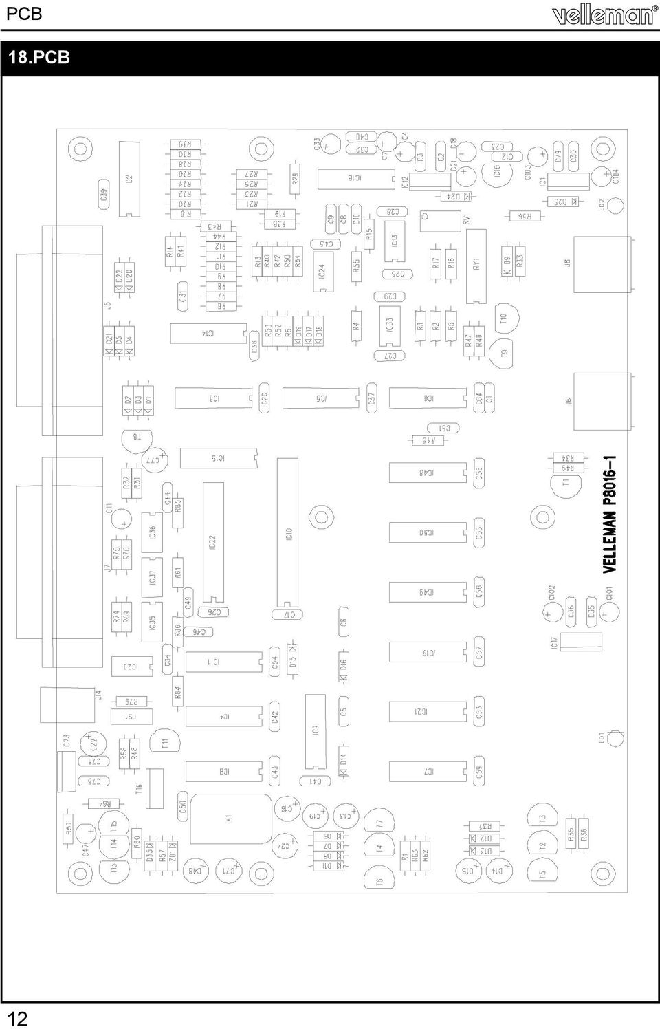
12 PCB PCB 12
13 Schematic diagram 19. Power supply section 13

14 Schematic diagram 20. Analogue section 14

15 Schematic diagram 21. Digital section 15

16 VELLEMAN KIT NV Legen Heirweg Gavere Belgium Europe Info?: Questions?: Modifications and typographical errors reserved Velleman Kit nv H8016IP ED1 (rev1)

DIGITAL PC SCOPE. Total solder points: 625 Difficulty level: beginner 1 2 3 4 5 advanced K8031 ILLUSTRATED ASSEMBLY MANUAL
 DIGITAL PC SCOPE Digital storage oscilloscoop, using a computer and its monitor to display waveforms. All standard oscilloscope functions are available in the Windows program supplied. Total solder points:
POCKET AUDIO GENERATOR K8065
 POCKET AUDIO GENERATOR K8065 Great little gadget for service repair, testing, education, etc... ILLUSTRATED ASSEMBLY MANUAL H8065IP-1 VELLEMAN NV Legen Heirweg 33 9890 Gavere Belgium Europe www.velleman.be
Total solder points: 115 Difficulty level: beginner 1 2 3 4 5 advanced 4 CHANNEL RUNNING LIGHT K8032 ILLUSTRATED ASSEMBLY MANUAL
 Total solder points: 115 Difficulty level: beginner 1 2 3 4 5 advanced 4 CHANNEL RUNNING LIGHT K8032 Ideal for creating disco light effects, light speed adjustable. Suited for inductive loads. ILLUSTRATED
Total solder points: 205 Difficulty level: beginner 1 2 3 4 5 advanced UNIVERSAL BATTERY CHARGER / DISCHARGER K7300 ILLUSTRATED ASSEMBLY MANUAL
 Total solder points: 205 Difficulty level: beginner 1 2 3 4 5 advanced UNIVERSAL BATTERY CHARGER / DISCHARGER K7300 Automatic (dis)charging of both NiCd and NiMH batteries. ILLUSTRATED ASSEMBLY MANUAL
K2570 UNIVERSAL POWER SUPPLY 5-14DC / 1A. The easy way to power your ILLUSTRATED ASSEMBLY MANUAL
 Total solder points: 18 Difficulty level: beginner 1 2 3 4 5 advanced UNIVERSAL POWER SUPPLY 5-14DC / 1A K2570 The easy way to power your projects. ILLUSTRATED ASSEMBLY MANUAL H2570IP-1 Features & Specifications
7-SEGMENT DIGITAL CLOCK
 57mm 7-SEGMENT DIGITAL CLOCK Large 57mm clock & temperature display with extra unique feature Total solder points: 263 Difficulty level: beginner 1 2 3 4 5 advanced K8089 ILLUSTRATED ASSEMBLY MANUAL H8089IP-1
Total solder points: 18 Difficulty level: beginner 1 2 3 4 5 advanced UNIVERSAL POWER SUPPLY 5-14DC / 1A K2570 ILLUSTRATED ASSEMBLY MANUAL
 Total solder points: 18 Difficulty level: beginner 1 2 3 4 5 advanced UNIVERSAL POWER SUPPLY 5-14DC / 1A K2570 The easy way to power your projects. ILLUSTRATED ASSEMBLY MANUAL H2570IP-1 Features & Specifications
Total solder points: 67 Difficulty level: beginner 1 2 3. 4 5 advanced UNIVERSAL TEMPERATURE SENSOR K8067 ILLUSTRATED ASSEMBLY MANUAL
 Total solder points: 67 Difficulty level: beginner 1 2 3 4 5 advanced UNIVERSAL TEMPERATURE SENSOR K8067 Ideal for connection to computer interface boards (K8000, K8055, K8047,..) ILLUSTRATED ASSEMBLY
VOLUME AND TONE CONTROL - PREAMPLIFIER K8084
 H8084IP-1 VOLUME AND TONE CONTROL - PREAMPLIFIER K8084 When using one of our amplifiers (big or small), you always need a volume control and preferably also a tone control Features & specifications When
Total solder points: 57 Difficulty level: beginner 1 2 3 4 5 advanced 3 TO 30VDC / 3A POWER SUPPLY K7203 ILLUSTRATED ASSEMBLY MANUAL H7203IP-1
 Total solder points: 57 Difficulty level: beginner 1 2 3 4 5 advanced 3 TO 30VDC / 3A POWER SUPPLY K7203 A power supply for all our kits, based on a stabilised DC voltage of 30V. ILLUSTRATED ASSEMBLY MANUAL
GUITAR PREAMPLIFIER WITH HEADPHONE OUTPUT K4102
 H4102IP-1 GUITAR PREAMPLIFIER WITH HEADPHONE OUTPUT K4102 Practice the guitar without disturbing others. Features & Specifications Features: An electric guitar cannot be connected to just any amplifier
DUAL ELECTRONIC DICE K3400
 DUAL ELECTRONIC DICE K3400 Cheating is no longer possible! ILLUSTRATED ASSEMBLY MANUAL H3400IP-1 VELLEMAN NV Legen Heirweg 33 9890 Gavere Belgium Europe www.velleman.be www.velleman-kit.com Features &
SYMMETRIC 1A POWER SUPPLY K8042
 SYMMETRIC 1A POWER SUPPLY K8042 Low cost universal symmetric power supply ILLUSTRATED ASSEMBLY MANUAL H8042IP-1 Features & Specifications Features low cost universal symmetric power supply just add a suitable
200W DISCRETE POWER AMPLIFIER K8060
 H8060IP-1 200W DISCRETE POWER AMPLIFIER K8060 Ideal for active speaker system or subwoofer, guitar amp, home theatre systems, instrument amp, etc. Features & Specifications Specifications: Excellent value
MAINS VOLTAGE DETECTOR K7101
 With this device wires can be very easily checked for mains voltage. H7101IP-1 MAINS VOLTAGE DETECTOR K7101 VELLEMAN NV Legen Heirweg 33 9890 Gavere Belgium Europe www.velleman.be www.velleman-kit.com
Total solder points: 167 Difficulty level: beginner 1 2 3 4 5 advanced DMX CONTROLLED RELAY K8072 ILLUSTRATED ASSEMBLY MANUAL
 Total solder points: 167 Difficulty level: beginner 1 2 3 4 5 advanced DMX CONTROLLED RELAY K8072 Control a relay by means of the wellknown DMX512 protocol. ILLUSTRATED ASSEMBLY MANUAL H8072IP-1 Features
Total solder points: 147 Difficulty level: beginner 1 2 3 4 5 advanced VIDEO SIGNAL CLEANER K8036 ILLUSTRATED ASSEMBLY MANUAL
 Total solder points: 147 Difficulty level: beginner 1 2 3 4 5 advanced VIDEO SIGNAL CLEANER K8036 Digitally cleans the video signal of unwanted distortions and improves the picture quality. ILLUSTRATED
K4401 SOUND GENERATOR. them at the touch of a button. Specifications
 SOUND GENERATOR K4401 Sound effects, tunes, sirens... 10 of them at the touch of a button. Specifications Loudspeakers output : 8 ohm/1w Line output : 1VRms. Power supply : 8 10VDC (9v battery). Max. current
15 Channel IR transmitter. Total solder points: 53 Difficulty level: beginner 1 2 3 4 5 advanced K8049 ILLUSTRATED ASSEMBLY MANUAL
 15 Channel IR transmitter Compatible with most Velleman IR receiver kits, 4 adresses allow the use of multiple receivers in one room. Total solder points: 53 Difficulty level: beginner 1 2 3 4 5 advanced
400W MONO/STEREO AMPLIFIER
 400W MONO/STEREO AMPLIFIER Universal, robust and compact are the words to describe this amplifier. Total solder points: 264 Difficulty level: beginner 1 2 3 4 5 advanced K4005B ILLUSTRATED ASSEMBLY MANUAL
Total solder points: 129 Difficulty level: beginner 1 2 3 4 5 advanced LIQUID LEVEL CONTROLLER K2639 ILLUSTRATED ASSEMBLY MANUAL H2639IP-1
 Total solder points: 129 Difficulty level: beginner 1 2 3 4 5 advanced LIQUID LEVEL CONTROLLER K2639 Forgotten to turn off the tap, leaking washing machines,... Prevention is better than cure. So use this
K6002 TEMPERATURE CONTROLLER. Specifications
 Total solder points: 169 + 99 + 67 Difficulty level: beginner 1 2 3 4 5 advanced TEMPERATURE CONTROLLER K6002 Unlike a normal thermostat, this kit has two outputs, one for "high" alarm and one for "low"
Total solder points: 248 Difficulty level: beginner 1 2 3 4 5 advanced. 15 Channel infrared receiver K8050 ILLUSTRATED ASSEMBLY MANUAL
 Total solder points: 48 Difficulty level: beginner 4 5 advanced 5 Channel infrared receiver K8050 IR-Remote control transmitters allow you to control 5 opencollector contacts ILLUSTRATED ASSEMBLY MANUAL
K8068 BUS DIMMER FOR HOME MODULAR LIGHT SYSTEM ILLUSTRATED ASSEMBLY MANUAL H8068IP-1
 Total solder points: 74 Difficulty level: beginner 1 2 3 4 5 advanced BUS DIMMER FOR HOME MODULAR LIGHT SYSTEM K8068 PLUG - IN module for use with home modular lights system K8006. For electronic transformers!
K8025 VIDEO PATTERN GENERATOR. Check the picture quality of your monitor or TV, ideal for adjustment or troubleshooting.
 K8025 ILLUSTRATED ASSEMBLY MANUAL H8025IP 1 VIDEO PATTERN GENERATOR Check the picture quality of your monitor or TV, ideal for adjustment or troubleshooting. Forum Participate our Velleman Projects Forum
POWERBLOCK - POWER AMPLIFIER
 POWERBLOCK - POWER AMPLIFIER This amplifier is an ideal set-up for active speaker use. Total solder points: 383 Difficulty level: beginner 1 2 3 4 5 advanced K8081 ILLUSTRATED ASSEMBLY MANUAL H8081IP-1
Total solder points: 85 Difficulty level: beginner 1 2 3 4 5 advanced MULTIFUNCTION RELAY SWITCH K8015 ILLUSTRATED ASSEMBLY MANUAL H8015IP-2
 Total solder points: 85 Difficulty level: beginner 1 2 3 4 5 advanced MULTIFUNCTION RELAY SWITCH K8015 14 Different functions including timers, switching, flashing, interval, random switching,... ILLUSTRATED
ELECTRONIC TRANSISTOR IGNITION FOR CARS K2543
 H2543IP 1 ELECTRONIC TRANSISTOR IGNITION FOR CARS K2543 Gives your car a better starting and smoother running. Suitbale for 12V and 6V systems. Features & Specifications Even the most sceptical one has
The new Velleman Projects catalogue is now available. Download your copy here: www.vellemanprojects.eu
 The new Velleman Projects catalogue is now available. Download your copy here: www.vellemanprojects.eu Modifications and typographical errors reserved - Velleman nv. H8098 IP 2 (rev.1.0) Velleman NV, Legen
With the K8097 4-channel stepper motor card you can drive 4 stepper motors via USB, and monitor and assign actions if needed to 5 dry contacts
 K8097 K80977IP ILLUSTRATED LU TED ASSEMBLY SEMB MANUAL H8097IP - Channel USB stepper motor card With the K8097 -channel stepper motor card you can drive stepper motors via USB, and monitor and assign actions
100W SUBWOOFER KIT. Total solder points: 383 Difficulty level: beginner 1 2 3 4 5 advanced K8077 ILLUSTRATED ASSEMBLY MANUAL
 100W SUBWOOFER KIT Powerful bass from a small cabinet thanks to the dual speaker principle Total solder points: 383 Difficulty level: beginner 1 2 3 4 5 advanced K8077 ILLUSTRATED ASSEMBLY MANUAL H8077IP-1
K8048 PIC PROGRAMMER AND EXPERIMENT BOARD. Specifications
 Total solder points: 274 Difficulty level: beginner 1 2 3 4 5 advanced PIC PROGRAMMER AND EXPERIMENT BOARD K8048 Suitable for programming Microchip Flash PIC TM microcontrollers. Basic programming knowledge
3.5A SUPPRESSED DIMMER K8026
 Total solder points: 29 Difficulty level: beginner 1 2 3 4 5 3.5A SUPPRESSED DIMMER K8026 Dimmer for incandescent lightbulbs and collector motors Fuse protected AC power : 110-125 or 220-240VAC 50/60Hz
Dc to Pulse Width Modulator
 Total solder points: 82 Difficulty level: beginner 1 2 3 4 5 advanced Dc to Pulse Width Modulator Hardware: K8004 PWM range: 0 to 100% PWM frequency: 100 to 5000Hz adjustable Minimum PWM offset: 0 to 20%
Assembly and User Guide
 1 Amp Adjustable Electronic Load 30V Max, 1 Amp, 20 Watts Powered by: 9V Battery Assembly and User Guide Pico Load is a convenient constant current load for testing batteries and power supplies. The digital
Fan timer K8041. Features: Specifications :
 Total solder points: 101 Difficulty level: beginner 1 2 3 4 5 advanced Features: Fan timer K8041 Suitable for most types of ventilators Solid state switching with noise suppression Can be connected to
TRANSISTOR IGNITION K2543
 Total solder points: 38 Skill level : Beginner 1 2 3 4 5 Advanced HIGH-Q TRANSISTOR IGNITION K2543 Applications : Upgrade the existing ignition system of : Cars, motorcycles, mowers, outboards, Reduces
Total solder points: 202 Difficulty level: beginner 1 2 3 4 5 advanced. PIC programmer board K8076 ILLUSTRATED ASSEMBLY MANUAL
 Total solder points: 0 Difficulty level: beginner advanced PIC programmer board K0 This board can program a wide range of Microchip PIC microcontrollers ILLUSTRATED ASSEMBLY MANUAL H0IP- This device complies
DUAL ELECTRONIC DICE K3400
 Total solder points: 198 Skill level : Beginner 1 2 3 4 5 Advanced DUAL ELECTRONIC DICE K3400 Features: Two independent dice Use a single or both dice at the same time Display auto shut-off saves battery
Stereo valve power amplifier
 Stereo valve power amplifier For most of us a high power valve amplifier is unaffordable. This kit changes that, so that now everybody can enjoy that sublime "valve sound". Total solder points: 00 Difficulty
DC CONTROLLED DIMMER Manual
 Total solder points: 61 Skill level : Beginner 1 2 3 4 5 Advanced K8003 DC CONTROLLED DIMMER Manual This small but handy circuit is ideal for replacing an existing dimmer or switch, in order to be able
Cumbria Designs T-1. SSB/CW Filter kit (4.9152MHz) User Manual
 User Manual") Cumbria Designs T-1 SSB/CW Filter kit (4.9152MHz) User Manual CONTENTS 1 INTRODUCTION 2 2 CIRCUIT DESCRIPTION 2 3 ASSEMBLY 2 4 TESTING 4 The Steading Stainton PENRITH Cumbria CA11 0ES UK 1 Introduction
Cumbria Designs T-1 SSB/CW Filter kit (4.9152MHz) User Manual CONTENTS 1 INTRODUCTION 2 2 CIRCUIT DESCRIPTION 2 3 ASSEMBLY 2 4 TESTING 4 The Steading Stainton PENRITH Cumbria CA11 0ES UK 1 Introduction
4 channel recorder / logger
 Total solder points: 159 Difficulty level: beginner 1 2 3 4 5 advanced 4 channel recorder / logger Hardware: USB connected and powered. Four DC coupled input channels. Input resistance 1Mohm. Maximum samples
Electronics. Discrete assembly of an operational amplifier as a transistor circuit. LD Physics Leaflets P4.2.1.1
 Electronics Operational Amplifier Internal design of an operational amplifier LD Physics Leaflets Discrete assembly of an operational amplifier as a transistor circuit P4.2.1.1 Objects of the experiment
Kit 106. 50 Watt Audio Amplifier
 Kit 106 50 Watt Audio Amplifier T his kit is based on an amazing IC amplifier module from ST Electronics, the TDA7294 It is intended for use as a high quality audio class AB amplifier in hi-fi applications
Kit 27. 1W TDA7052 POWER AMPLIFIER
 Kit 27. 1W TDA7052 POWER AMPLIFIER This is a 1 watt mono amplifier Kit module using the TDA7052 from Philips. (Note, no suffix.) It is designed to be used as a building block in other projects where a
RS232/DB9 An RS232 to TTL Level Converter
 RS232/DB9 An RS232 to TTL Level Converter The RS232/DB9 is designed to convert TTL level signals into RS232 level signals. This cable allows you to connect a TTL level device, such as the serial port on
DDS VFO CONSTRUCTION MANUAL. DDS VFO Construction Manual Issue 1 Page 1
 DDS VFO CONSTRUCTION MANUAL DDS VFO Construction Manual Issue 1 Page 1 Important Please read before starting assembly STATIC PRECAUTION The DDS VFO kit contains the following components which can be damaged
LM566C Voltage Controlled Oscillator
 LM566C Voltage Controlled Oscillator General Description The LM566CN is a general purpose voltage controlled oscillator which may be used to generate square and triangular waves the frequency of which
Reading: HH Sections 4.11 4.13, 4.19 4.20 (pgs. 189-212, 222 224)
") 6 OP AMPS II 6 Op Amps II In the previous lab, you explored several applications of op amps. In this exercise, you will look at some of their limitations. You will also examine the op amp integrator and
6 OP AMPS II 6 Op Amps II In the previous lab, you explored several applications of op amps. In this exercise, you will look at some of their limitations. You will also examine the op amp integrator and
Modifying the Yaesu FT-847 External 22.625 MHz Reference Input
 Modifying the Yaesu FT-847 External 22.625 MHz Reference Input David Smith VK3HZ Introduction This document describes the modification of an FT-847 to allow an external 22.625 MHz Reference oscillator
Ocean Controls RC Servo Motor Controller
 Ocean Controls RC Servo Motor Controller RC Servo Motors: RC Servo motors are used in radio-controlled model cars and planes, robotics, special effects, test equipment and industrial automation. At the
QUASAR ELECTRONICS KIT No. 1015 ELECTRONIC MOSQUITO REPELLER
 QUASAR ELECTRONICS KIT No. 1015 ELECTRONIC MOSQUITO REPELLER General Description This simple circuit can prove itself worth many times its value (which is very reasonable anyway) in getting rid of mosquitoes
Annex: VISIR Remote Laboratory
 Open Learning Approach with Remote Experiments 518987-LLP-1-2011-1-ES-KA3-KA3MP Multilateral Projects UNIVERSITY OF DEUSTO Annex: VISIR Remote Laboratory OLAREX project report Olga Dziabenko, Unai Hernandez
A CW QRP Transceiver for 20 m band. How it works I'll describe individually the three boards and the relative tuning devices.
 A CW QRP Transceiver for 20 m band The little QRP presented in this article may be built in a gradual manner, in fact it is divided in two main modules (plus VFO), you may also complete only a single part
ARDUINO SEVERINO SERIAL SINGLE SIDED VERSION 3 S3v3 (REVISION 2) USER MANUAL
 USER MANUAL") ARDUINO SEVERINO SERIAL SINGLE SIDED VERSION 3 S3v3 (REVISION 2) USER MANUAL X1: DE-9 serial connector Used to connect computer (or other devices) using RS-232 standard. Needs a serial cable, with at least
ARDUINO SEVERINO SERIAL SINGLE SIDED VERSION 3 S3v3 (REVISION 2) USER MANUAL X1: DE-9 serial connector Used to connect computer (or other devices) using RS-232 standard. Needs a serial cable, with at least
BMD16N-SD. version 1.2
 BMD16NSD version 1.2 Feedback decoder with 16 contacts with integrated current detection for the S88bus Compatible with a.o. Märklin Digital, Uhlenbrock Intellibox, Fleischmann TwinCenter and LDT HSI88
Build A Video Switcher. Reprinted with permission from Electronics Now Magazine September 1997 issue
 Build A Video Switcher Reprinted with permission from Electronics Now Magazine September 1997 issue Copyright Gernsback Publications, Inc.,1997 BUILD A VIDEO SWITCHER FRANK MONTEGARI Watch several cameras
Joule Thief 3.0 Kit. June 2012, Rev 1 1 http://www.easternvoltageresearch.com Joule Thief 3.0
 Kit Instruction Manual Eastern Voltage Research, LLC June 2012, Rev 1 1 http://www.easternvoltageresearch.com HIGH BRIGHTNESS LED THIS KIT USES A 1W CREE, HIGH BRIGHTNESS LED. DO NOT STARE AT THIS (OR
LIGHT COMPUTER K5201
 Total solder points: 240 Skill level : Beginner 1 2 3 4 5 Advanced LIGHT COMPUTER K5201 Features: Sixteen different patterns and 7 outputs provide a unique light show Easy pattern selection with rotary
Amplifier for Small Magnetic and Electric Wideband Receiving Antennas (model AAA-1B)
") Amplifier for Small Magnetic and Electric Wideband Receiving Antennas (model AAA-1B) 1. Description and Specifications Contents 1.1 Description 1.2 1.2 Specifications 1.3 1.3 Tested parameters in production
Amplifier for Small Magnetic and Electric Wideband Receiving Antennas (model AAA-1B) 1. Description and Specifications Contents 1.1 Description 1.2 1.2 Specifications 1.3 1.3 Tested parameters in production
ECEN 1400, Introduction to Analog and Digital Electronics
 ECEN 1400, Introduction to Analog and Digital Electronics Lab 4: Power supply 1 INTRODUCTION This lab will span two lab periods. In this lab, you will create the power supply that transforms the AC wall
GLOLAB Universal Telephone Hold
 GLOLAB Universal Telephone Hold 1 UNIVERSAL HOLD CIRCUIT If you have touch tone telephone service, you can now put a call on hold from any phone in the house, even from cordless phones and phones without
Analog Electronics I. Laboratory
 Analog Electronics I Laboratory Exercise 1 DC Power Supply Circuits Aim of the exercise The aim of this laboratory exercise is to become familiar with rectifying circuits and voltage stabilization techniques
AUTOMATIC CALL RECORDER JAMECO PART NO. 2163735
 AUTOMATIC CALL RECORDER JAMECO PART NO. 2163735 Experience Level: Intermediate Time Required: 1-2 Hours This project automatically records phone calls. The program, along with the adapter records each
TECHNICAL DATASHEET #TD1404AX PWM CONTROLLED SOLENOID DRIVER
 TECHNICAL DATASHEET #TD1404AX PWM CONTROLLED SOLENOID DRIVER (PWM Input, 1.2A or 2A Output, Metal Box or PCB) PCB Board - P/N: PWMC-PCB-2A, PWMC-PCB-1.2A Packaged Driver (metal box with 1.5 m (5 ft.) cable)
LAB 1 TECHNICAL DOC 3 IN ONE LAB DEVICE. Velleman Legen Heirweg 33 9890 Gavere Belgium
 LAB 1 TECHNICAL DOC 3 IN ONE LAB DEVICE Velleman Legen Heirweg 33 9890 Gavere Belgium SPECIFICATIONS DIGITAL MULTIMETER 3 1/2 backlit LCD Automatic polarity indication DC voltage 200mV to 600V in 5 steps
Build a Voltage and Current Peak Detector
 ax You Can DIY! Build a Voltage and Current Peak Detector Here is a simple portable device that can help answer the question about peak voltage and peak current requirements and whether or not your power
Contractors Guide Central Inverter System Installation
 Contractors Guide Central Inverter System Installation Step By Step Procedures 2,200 Watt/VA 6 Step Installation 1. Mount Bottom Cabinet 2. Mount Top Cabinet 3. Install Batteries 4. Install Conduit 5.
How To Make A Feedback Decoder For A Model Railroad
 BMD16N version 1.2 Feedback decoder with 16 contacts for the S88-bus Compatible with a.o. Märklin Digital, Uhlenbrock Intellibox, Fleischmann Twin-Center and LDT HSI-88 Compatible with the s88-n standard
www.jameco.com 1-800-831-4242
 Distributed by: www.jameco.com 1-800-831-4242 The content and copyrights of the attached material are the property of its owner. LF411 Low Offset, Low Drift JFET Input Operational Amplifier General Description
FREQUENCY RESPONSE ANALYZERS
 FREQUENCY RESPONSE ANALYZERS Dynamic Response Analyzers Servo analyzers When you need to stabilize feedback loops to measure hardware characteristics to measure system response BAFCO, INC. 717 Mearns Road
POWER SUPPLY MODEL XP-15. Instruction Manual ELENCO
 POWER SUPPLY MODEL XP-15 Instruction Manual ELENCO Copyright 2013 by Elenco Electronics, Inc. REV-A 753020 All rights reserved. No part of this book shall be reproduced by any means; electronic, photocopying,
The Radio-Kits Digital SWR meter kit Construction and user manual
 The Radio-Kits Digital SWR meter kit Construction and user manual Author - Steve Drury G6ALU List of contents Section Page no. 1. Features and specifications 2 2. Introduction 2. Construction 4. General
POCKET SCOPE 2. The idea 2. Design criteria 3
 POCKET SCOPE 2 The idea 2 Design criteria 3 Microcontroller requirements 3 The microcontroller must have speed. 3 The microcontroller must have RAM. 3 The microcontroller must have secure Flash. 3 The
User s Guide DDS-3X25 USB ARBITRARY FUNCTION GENERATOR
 User s Guide DDS-3X25 USB ARBITRARY FUNCTION GENERATOR Content General safety summary...1 Introduction...2 Chapter 1 Getting started...3 System Requirements...4 Installing Hardware...5 Installing Software...8
PicoScope 6000A/B Series
 PicoScope 6000A/B Series PC Oscilloscopes User's Guide -1 PicoScope 6000A/B Series User's Guide I Contents 1 Welcome...1 2 Introduction...2 1 Using this guide 2 Safety symbols 3 Safety warnings 4 FCC
Adjustment functions for both span and shift have been incorporated
 SENSORS FOR SERIES LED Type Wafer Alignment Sensor FX-0-F FT-F9 FD-F7 EX-F70/F60 M SH-7 FD-L4 M-DW The use of a safe LED light beam now allows for high precision detection with a resolution of 0!m (.8
SYSTEM 4C. C R H Electronics Design
 SYSTEM 4C C R H Electronics Design SYSTEM 4C All in one modular 4 axis CNC drive board By C R Harding Specifications Main PCB & Input PCB Available with up to 4 Axis X, Y, Z, A outputs. Independent 25
Elecraft K3 KPA3 Power Connector Replacement Revision A Review, April 16, 2012 Copyright 2012, Elecraft, Inc. All Rights Reserved
 Introduction Elecraft K3 KPA3 Power Connector Replacement Revision A Review, April 16, 2012 Copyright 2012, Elecraft, Inc. All Rights Reserved The connectors furnishing high current to the KPA3 module
K8009. Multifunctional clock display. Features : Specifications :
 Total solder points: 775 Difficulty level: beginner 2 3 4 5 advanced Features : Multifunctional clock display K8009 6 x 36mm high digits. Time, date & temperature indication, selectable with toggle option.
Neo-Neon. LED Vision Mesh Screen Operation Manual. LED Vision Mesh Screen. Neo-Neon International Ltd He Shan Decorative Lighting Company Limited
 Neo-Neon LED Vision Mesh Screen Operation Manual He Shan Decorative Lighting Company Limited LED Display Engineering Department 1 Contents Chapter1 Specification and Function Parameters 3 Chapeter2 Structure
HagUsb USB to S/PDIF Converter
 HAGERMAN T E C H N O L O G Y HagUsb USB to S/PDIF Converter HagUsb USB to S/PDIF Kit Manual 2 Warnings This product uses no lethal or dangerous voltages. However, installation into a CD player or transport
Single Transistor FM Transmitter Design
 Single Transistor FM Transmitter Design In telecommunications, frequency modulation (FM) conveys information over a carrier wave by varying its frequency. FM is commonly used at VHF radio frequencies for
Programmable Single-/Dual-/Triple- Tone Gong SAE 800
 Programmable Single-/Dual-/Triple- Tone Gong Preliminary Data SAE 800 Bipolar IC Features Supply voltage range 2.8 V to 18 V Few external components (no electrolytic capacitor) 1 tone, 2 tones, 3 tones
AC Measurements Using the Oscilloscope and Multimeter by Mr. David Fritz
 AC Measurements Using the Oscilloscope and Multimeter by Mr. David Fritz 1 Sine wave with a DC offset f = frequency in Hz A = DC offset voltage (average voltage) B = Sine amplitude Vpp = 2B Vmax = A +
AXE114S BINARY CLOCK. revolution Revolution Education Ltd. Email: info@rev-ed.co.uk Web: www.rev-ed.co.uk Version 1.1 12/09/08 AXE114.PMD.
 AXE114S BINARY CLOCK Features: The PICAXE binary clock kit tells the time by lighting up blue LEDs in a binary pattern. This is a useful tool for teaching students binary code or simply just confusing/
Contents. Safety Warnings... 1
 Contents Safety Warnings... 1 Unpacking the GQ600... 1 Introduction... 2 GQ600 Filter Characteristics... 2 1/3 Octave Centre Frequencies... 4 Front Panel Functions... 5 Rear Panel Functions... 6 Specifications...
A Versatile Audio Amplifier
 A Versatile Audio Amplifier...built around the TBA 810 Integrated Circuit You can build a versatile audio amplifier for your workbench or for any other of your audio projects...with the TBA 810 IC (Integrated
FTDI VCP DRIVER (free) (WIN/MAC/LINUX) http://www.ftdichip.com/drivers/vcp.htm
 (WIN/MAC/LINUX) http://www.ftdichip.com/drivers/vcp.htm") 002 - CONNECTING THE PRINTER Now that you have an idea what 3D printing entails, we can continue and connect the printer to your computer. First make sure you have a computer with a decent amount of RAM
002 - CONNECTING THE PRINTER Now that you have an idea what 3D printing entails, we can continue and connect the printer to your computer. First make sure you have a computer with a decent amount of RAM
PowerFlex 700H and 700S AC Drives Frame 11 Main Fan Capacitor Replacement Kit
 Installation Instructions PowerFlex 700H and 700S AC Drives Frame 11 Main Fan Capacitor Replacement Kit ATTENTION: The sheet metal cover and mounting screws on the ASIC Board located on the power structure
LM386 Low Voltage Audio Power Amplifier
 Low Voltage Audio Power Amplifier General Description The LM386 is a power amplifier designed for use in low voltage consumer applications. The gain is internally set to 20 to keep external part count
AutoRanging Digital MultiMeter
 Owner's Manual AutoRanging Digital MultiMeter Model No. 82139 CAUTION: Read, understand and follow Safety Rules and Operating Instructions in this manual before using this product. Safety Operation Maintenance
PIC-GEN FREQUENCY GENERATOR/ COUNTER by JOHN BECKER
 PIC-GEN FREQUENCY GENERATOR/ COUNTER by JOHN BECKER Add even more versatility to your workshop facilities. Combining the sophisticated features of a Maxim MAX038 waveform generator and a PIC6F877 microcontroller
IRT Eurocard. Types DAX-3200
 I R T Electronics Pty Ltd A.B.N. 35 000 832 575 26 Hotham Parade, ARTARMON N.S.W. 2064 AUSTRALIA National: Phone: (02) 9489 3744 Fax: (02) 9439 7439 International: +61 2 9439 3744 +61 2 9439 7439 Email:
ISC Dual Frequency WFS RFPD Test Procedure:
 LASER INTERFEROMETER GRAVITATIONAL WAVE OBSERVATORY LIGO Laboratory / LIGO Scientific Collaboration LIGO 08 January 2013 ISC Dual Frequency WFS RFPD Test Procedure: Richard Abbott Distribution of this
The quadrature signals and the index pulse are accessed through five 0.025 inch square pins located on 0.1 inch centers.
 Quick Assembly Two and Three Channel Optical Encoders Technical Data HEDM-550x/560x HEDS-550x/554x HEDS-560x/564x Features Two Channel Quadrature Output with Optional Index Pulse Quick and Easy Assembly
PolyBot Board. User's Guide V1.11 9/20/08
 PolyBot Board User's Guide V1.11 9/20/08 PolyBot Board v1.1 16 pin LCD connector 4-pin SPI port (can be used as digital I/O) 10 Analog inputs +5V GND GND JP_PWR 3-pin logic power jumper (short top 2 pins
DATA SHEET. TDA1543 Dual 16-bit DAC (economy version) (I 2 S input format) INTEGRATED CIRCUITS
 (I 2 S input format) INTEGRATED CIRCUITS") INTEGRATED CIRCUITS DATA SHEET File under Integrated Circuits, IC01 February 1991 FEATURES Low distortion 16-bit dynamic range 4 oversampling possible Single 5 V power supply No external components required
INTEGRATED CIRCUITS DATA SHEET File under Integrated Circuits, IC01 February 1991 FEATURES Low distortion 16-bit dynamic range 4 oversampling possible Single 5 V power supply No external components required