|
|
|
- Kerry Farmer
- 8 years ago
- Views:
Transcription
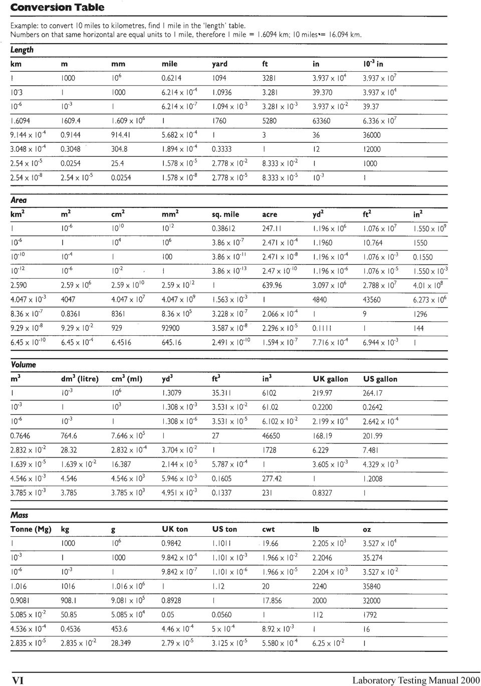
1 Laboratory Testing 2000

2 THE UNITED REPUBLIC OF TANZANIA MINISTRY OF WORKS Laboratory Testing Manual 2000 I Laboratory Testing Manual 2000

3 June 2000 ISBN Reproduction of extracts from this Manual may be made subject to due acknowledgement of the source. Although this Manual is believed to be correct at the time of printing, does not accept any contractual, tortious or other form of liability for its contents or for any consequences arising from its use. People using the information contained in the Manual should apply and rely on their own skill and judgement to the particular issue that they are considering. Printed by: Novum Grafisk AS, Skjetten Norway Layout: Jan Edvardsen, ICG Oslo Norway II Laboratory Testing Manual 2000

4 Preface The importance of standardized and consistent test procedures in road construction in order to establish quality can not be over emphasized. This Manual describes the procedures for laboratory testing of road construction and building materials carried out at the (CML). The test procedures are in essence based on British Standard (BS) for testing of soils, aggregates and concrete. American Society for Testing and Materials (ASTM) have been used for asphalt testing. These procedures are in accordance with the requirements referred to in the, Pavement and Materials Design Manual of 1999 and Standard Specifications for Road Works of It has been said that, One test result is worth a hundred expert opinions, but this is only true if such a result is truly accurate and relevant for its application. In practice, it is essential that test procedures are clearly specified and that their fields of application and limitations are clearly understood. It is in this context this Manual has been compiled, although simplified to a more practical approach to make it easier to do the tests. However, after saying so the performances of the tests are in accordance with the relevant standards i.e. BS and ASTM. The described test procedures are standards for testing of road construction materials and shall under no circumstances be diverted from. Hence, consistent and high quality laboratory routines are essential, so are the quality assurance of test results and test equipment. Only these can produce reliable results, which can be used to predict and explain the performance of road construction materials. Preparation of this Manual has been a component under the Institutional Co-operation between the and the Norwegian Public Roads Administration (NPRA) to support and improve the capacity at the Central Materials Laboratory (CML). The Government of Tanzania and the Norwegian Agency for International Development (NORAD) have jointly financed the project., Dar es Salaam June, 2000 III Laboratory Testing Manual 2000

5 Acknowledgements This Laboratory Testing Manual 1999 has been prepared as a component under the Institutional Co-operation between (MoW), (CML) and the Norwegian Public Roads Administration (NPRA). The Government of Tanzania and the Norwegian Agency for International Development (NORAD) have jointly financed the project, which forms part of a programme to establish technical standards and guidelines for highway engineering. This Manual has been prepared by a number of peoples, under the project management by the two project engineers: Mr. S.S. Rutajama, CML Mr. C. Overby, NPRA The following persons have contributed to this Laboratory Testing Manual: Mr. J. Y. Mrema, CML Mr. A. Mtola, CML Mr. O. Mtavangu, CML Mr. H. Kapombe, CML Mr. P. Mazzuki, CML Mr. B. Mariki, CML Mr. T. Lyanga, CML Mr. O. Salehe, CML Ms. N. Bugenyi, CML Mr. S. Nergaard, NOTEBY Mr. A. Soegaard, NOTEBY Mr. E. O. Andersen, SINTEF Mr. S. Hoseth, SINTEF Mr. R. Johansen, ViaNova The project management wish to acknowledge the significant contribution from all people involved giving critical comments during various phases in compiling this report. IV Laboratory Testing Manual 2000

6 Table of contents CML test method, reference number Name of test Reference to test methods Tests on Soils and Gravels 1.1 Moisture Content BS1377:Part 2: Liquid Limit (Cone Penetrometer) BS1377:Part 2: Plastic Limit & Plasticity Index BS1377:Part 2: Linear Shrinkage BS1377:Part 2: Particle Density Determination - Pyknometer BS1377:Part 2: Bulk Density for undisturbed samples BS1377:Part 2: Particle Size Distribution - Wet sieving BS1377:Part 2: Particle Size Distribution - Hydrometer Method BS1377:Part 2: Compaction Test - BS Light and BS Heavy BS1377:Part 4: CBR Test - One point method CBR Test - Three point method BS1377:Part 4:1990 BS1377:Part 4:1990 and TMH1:method A8: Consolidation Test - Oedometer BS1377:Part 5: Triaxial Test BS1377:Part 7: Shear Box Test BS1377:Part 7: Permeability Test - Constant Head Organic Content - Ignition Loss Method BS1377:Part 5:1990 BS1377:Part 3:1990 and NPRA 014 test Crumb Test BS1377:Part 5: ph Value (ph meter) Preparation of Stabilised Samples for UCS Compaction Test - Stabilised Materials BS1377:Part 3:1990 TMH1:method A14:1986 and BS1924:Part 2:1990 TMH1:method A14:1986 and BS1924:Part 2: UCS of Stabilised Materials TMH1:method A14: Initial Consumption of Lime - ICL BS1924:Part 2:1990 Tests on Aggregates and Concrete 2.1 Moisture Content of Aggregates BS812:Part 109: Relative Density and Water Absorption BS812:Part 2: Sieve Tests on Aggregates BS812:Part 103.1: Flakiness Index (FI) and Average Least Dimension (ALD) BS812:Section 105.1: Elongation Index BS812:Section 105.2: Aggregate Crushing Value (ACV) BS812:Part 110: Ten Percent Fines Value (TFV) BS812:Part 111: Aggregate Impact Value (AIV) BS812:Part 112: Los Angeles Abrasion Test (LAA) ASTM C Sodium Soundness Test (SSS) ASTM C Slump Test BS1881:Part 102: Making of Concrete Test Cubes BS1881:Part 108: Concrete Cube Strength BS1881:Part 116:1983 Tests on Asphalt and Bituminous Materials 3.1 Pre-conditioning of Bitumen Samples Prior to Mixing or Testing NPRA 014 test Density of Bituminous Binders ASTM D Flash and Fire Point by Cleveland Open Cup ASTM D Thin-Film Oven Test (TFOT) ASTM D Penetration of Bituminous Materials ASTM D Softening Point Test ASTM D Ductility ASTM D Viscosity Determination using the Brookfield Thermosel Apparatus ASTM D Density and Water Absorption of Aggregates Retrieved on a 4.75 mm Sieve ASTM C Density and Water Absorption of Aggregates Passing the 4.75 mm Sieve ASTM C Calibration of Glass Pycnometers (0.5-1 litre) NPRA 014 test Mixing of Test Specimens; Hot Bituminous Mixes NPRA 014 test Determination of Maximum Theoretical Density of Asphalt Mixes and Absorption of Binder into Aggregates ASTM D and D Bulk Density of Saturated Surface Dry Asphalt Mix Samples ASTM D Bulk Density of Paraffin-Coated Asphalt Mix Samples ASTM D Bulk Density of Asphalt Mix Samples, Calliper Measurements NPRA 014 test Calculation of Void Content in Bituminous Mixes ASTM D3203 and AASHTO pp Marshall Test ASTM D Marshall Mix Design ASTM D Refusal Density Mix Design TRL Overseas Road Note 31, app. D: Indirect Tensile Strength Test ASTM D3967 and NPRA 014 test Determination of Binder Content and Aggregate Grading by Extraction ASTM D , method B 3.23 Effect of Water on Bituminous Coated Aggregates, Boiling Test ASTM D V Laboratory Testing Manual 2000

7 VI Laboratory Testing Manual 2000
8 VII Laboratory Testing Manual 2000

9 VIII Laboratory Testing Manual 2000

10 Soil Mechanics Testing CML test method, reference number Name of test Reference to test methods Tests on Soils and Gravels 1.1 Moisture Content BS1377:Part 2: Liquid Limit (Cone Penetrometer) BS1377:Part 2: Plastic Limit & Plasticity Index BS1377:Part 2: Linear Shrinkage BS1377:Part 2: Particle Density Determination - Pyknometer BS1377:Part 2: Bulk Density for undisturbed samples BS1377:Part 2: Particle Size Distribution - Wet sieving BS1377:Part 2: Particle Size Distribution - Hydrometer Method BS1377:Part 2: Compaction Test - BS Light and BS Heavy BS1377:Part 4: CBR Test - One point method BS1377:Part 4: CBR Test - Three point method BS1377:Part 4:1990 and TMH1:method A8: Consolidation Test - Oedometer BS1377:Part 5: Triaxial Test BS1377:Part 7: Shear Box Test BS1377:Part 7: Permeability Test - Constant Head BS1377:Part 5: Organic Content - Ignition Loss Method BS1377:Part 3:1990 and NPRA 014 test Crumb Test BS1377:Part 5: ph Value (ph meter) BS1377:Part 3: Preparation of Stabilised Samples for UCS TMH1:method A14:1986 and BS1924:Part 2: Compaction Test - Stabilised Materials TMH1:method A14:1986 and BS1924:Part 2: UCS of Stabilised Materials TMH1:method A14: Initial Consumption of Lime - ICL BS1924:Part 2:1990 Laboratory Testing Manual

11 1 Soil Mechanics TEST NO. 1.1 Moisture Content Objective To determine the amount of water present in a soil expressed as a percentage of the mass of dry soil. This is termed the moisture content of the soil. Main Principles The moisture content of a soil is assumed to be the amount of water within the pore space between the soil grains which is removable by ovendrying at a temperature not exceeding 110 C. The moisture content has a profound effect on soil behaviour. The oven-drying method is regarded as standard laboratory practice. References BS 1377 : Part 2 : Required equipment a drying oven with temperature of 105 C to 110 C a balance readable to 0,1 g a metal container a desiccator The actual drying time necessary will depend on of the type of soil, but 12 hours will be adequate for most soils. For calcrete and coral rock materials the drying temperature shall be limited to 60 C. Test Procedure Step 1: Clean and dry the container, then weigh it to the nearest 0.1 g (m 1 ) Step 2: A representative sample shall be crumbled and loosely placed in the container. - For fine-grained soils the sample weight shall be min. 30 g. - For medium-grained soils the sample weight shall be min. 300 g. - For coarse-grained soils the sample weight shall be min. 3 kg. Step 3: The container with sample shall immediately be weighed (m 2 ) and placed in the oven to dry at 105 C for minimum 12 hours. Step 4: After drying, weigh the container and the contents (m 3 ) Calculations Calculate the Moisture Content of the soil specimen, w, as a percentage of the dry soil mass to the nearest 0.1%, from the equation: W = ( m2 - m3 ) x 100 (%) m3 - m1 where m 1 is the mass of the container (in g) m 2 is the mass of the container and wet soil (in g) m 3 is the mass of the container and dry soil (in g) 2 Laboratory Testing Manual 2000

12 1 Soil Mechanics TEST NO. 1.1 Moisture Content Report The test report shall include the following: a) Type of material and sample identification b) Reference to this procedure c) Test results, individual values and average value d) The final moisture content (w) is reported to two significant figures. Form for the test The enclosed form Moisture Content shall be used. Practical Considerations One may control that the material is completely dry by holding a beaker with cold water directly above the sample. If the sample is not dry, moisture will condense on the outside of the glass. Maintenance The balance and the drying oven shall be checked and calibrated regularly (every month) with respect to weight and temperature. It is important that the containers are kept clean and dry. Laboratory Testing Manual

13 4 Laboratory Testing Manual 2000

14 1 Soil Mechanics TEST NO. 1.2 Liquid Limit (Cone penetrometer method) Objective The liquid limit is the empirically established moisture content at which a soil passes from the liquid state to the plastic state. The liquid limit provides a means of identifying and classifying finegrained cohesive soils especially when also the plastic limit is known. Variations in the moisture content in a soil may have significant effect on its shear strength, especially on fine-grained soils. Main Principles The cone penetrometer method is the preferred method to the Casagrande test as it is essentially a static test depending on soil shear strength. BS 1377 also describes a one-point cone penetrometer method. This method covers the determination of the liquid limit of a sample in its natural state, or a sample from which material retained on a 425 mm test sieve has been removed. It is based on the measurement of penetration into the soil of a standardised cone. References BS 1377 : Part 2 : If the soil in the natural state contains little or no material retaining larger than 425 mm, sieving is not necessary, eg. black cotton soil and red coffee soil. Any coarse particles can be removed by hand. The sample material must not be oven dried prior to testing. It is necessary to prepare the material one day in advance. Required equipment Test sieves of sizes 425 mm An airtight container A flat glass plate Two palette knives or spatulas A penetrometer A cone of stainless steel, 35 mm long with a smooth, polished surface and an angle of 30 having a mass of 80 g. A metal cup 55 mm in diameter and 40 mm deep with the rim parallel to the flat base An evaporating dish or a damp cloth Apparatus for moisture content determination A wash bottle containing clean water A metal straight edge A stopwatch Sample preparation Step 1: Take a sample of the soil of sufficient size to give a test specimen weighing about 400 g which passes the 425 mm sieve. This should be enough material for both Plastic Limit and Linear Shrinkage tests in addition to the Liquid Limit test. Step 2: Transfer the soil to a glass plate. Add water and mix thoroughly with two palette knives until the mass becomes a thick homogeneous paste. Step 3: Place the paste in an airtight container and allow to stand for hours to enable the water to permeate through the soil. Laboratory Testing Manual

15 1 Soil Mechanics TEST NO. 1.2 Liquid Limit (Cone penetrometer method) The sequence of the testing must be with increasing moisture content. If the soil has to be left for a while on the glass plate during the procedure, cover the soil with a damp cloth or the evaporating dish to prevent the soil from drying out When the penetration value is about 20 mm, set aside about 150 g of the sample for Linear Shrinkage and 50 g for Plastic Limit tests. The drying temperature for moisture content determination is generally 105 C to 110 C. However, for calcrete and coral rock materials the drying temperature shall be 60 C. Test Procedure Step 1: Take the 400 g soil sample and place it on a glass plate. Mix the paste for at least 10 minutes using the two palette knives. Add more distilled water if necessary so that the first cone penetro meter reading is about 15 mm. Step 2: Push a portion of the mixed soil into the cup with a palette knife, taking care not to trap air, gently tapping the cup against a firm surface if necessary. Strike off excess soil with the straightedge to give a smooth level surface. Step 3: With the penetration cone locked in the raised position lower the cone so that it just touches the surface of the soil. When the cone is in the correct position, a slight movement of cup will just mark the soil surface. Lower the dial gauge to contact the cone shaft and record the reading of the dial gauge to the nearest 0.1 mm. Step 4: Release the cone for a period of 5 ± 1 sec. After locking the cone in position, lower the dial gauge to contact the cone shaft and record the reading of the dial gauge to the nearest 0.1 mm. Record the difference between the readings as the cone penetration. Step 5: Lift out the cone and clean it carefully. Step 6: A little more wet soil shall be added to the cup and the process repeated. If the difference between the first and second penetration readings is less than 0.5 mm, the average of the two penetrations shall be recorded. If the second penetration is more than 0.5 mm and less than 1 mm different from the first, a third test shall be carried out. If the overall range is then not more than 1 mm, record the average of the 3 penetrations. If the overall range is more than 1 mm, the soil shall be removed from the cup, remixed and the test repeated until consistent results are obtained. Step 7: Take a moisture content sample of about 20 g from the area penetrated by the cone and determine the moisture content. Step 8: The penetration test shall be repeated at least three more times using the same sample of soil to which further increments of water have been added. The amount of water added shall be such that a range of penetration values of approximately 15 mm to 25 mm is covered by the four test runs. Step 9: Each time soil is removed from the cup for the addition of water, wash and dry the cup. 6 Laboratory Testing Manual 2000

16 1 Soil Mechanics TEST NO. 1.2 Liquid Limit (Cone penetrometer method) 1. Calculations Calculate the moisture content of each specimen. w = ( m2 - m3 ) x 100 (%) m3 - m1 where m 1 is the mass of the container (in g) m 2 is the mass of the container and wet soil (in g) m 3 is the mass of the container and dry soil (in g) 2. Plot the relationship between the moisture content and cone penetration with the moisture content as the abscissae and the cone penetration as ordinates, both on linear scales. 3. Draw the best straight line fitting the points. 4. The Liquid Limit (w L ) of the soil sample is the moisture content corresponding to a cone penetration of 20 mm and shall be expressed to the nearest whole number. Report The test report shall include the following: a) Type of material and sample identification b) Reference to this procedure c) Test result, i.e. the Liquid Limit of the soil sample d) Whether the material was tested in the natural state or after sieving Form for the test The enclosed form shall be used. Practical Considerations Take care not to damage the point of the cone by accidentally dropping the cone on the base plate. To avoid corrosion on the cone, it must be kept clean at all times. The cone corrodes easily, and rust could appear after just a few hours if it is left unclean. Maintenance Check the condition of the cone point with the test gauge. Check that the cone is falling freely without friction when released. Check the weight of the cone. Keep the equipment clean at all times. Laboratory Testing Manual

17 Figure 1. Details of cone forliquid limit test 8 Laboratory Testing Manual 2000

18 1 Soil Mechanics TEST NO. 1.3 Plastic Limit and Plasticity Index Objective The Plastic Limit is the empirically established moisture content at which a soil becomes too dry to be plastic. It is used together with the Liquid Limit to determine the Plasticity Index which when plotted against the Liquid Limit on the plasticity chart provides a means of classifying cohesive soils. The Plasticity Index is the difference between the Liquid Limit and the Plastic Limit. The Plasticity Index is the range of moisture content in which a soil is plastic; the finer the soil, the greater the Plasticity Index. Main Principles This method covers the determination of the liquid limit of a sample in its natural state, or a sample from which material retained on a 425 mm test sieve has been removed. References BS 1377 : Part 2 : Required equipment Two flat glass plates, one for mixing soil and one for rolling threads Two palette knives or spatulas Apparatus for moisture content determination Clean water A length of rod, 3 mm in diameter and 100 mm long Sample preparation This test commonly is performed as a continuance of the Liquid Limit test, and material for the test could conveniently be prepared as part of the Liquid Limit test. Otherwise a 40 g sample should be prepared in the same way as specified for the Liquid Limit test. Test Procedure Step 1: Take the 40 g soil paste sample and place it on a glass plate. The sample may be put out in the sun for a short period to speed up the drying process. A hairdryer may also be used. Alternatively a drying oven at a low temperature may be used. Step 2: Step 3: Step 4: Step 5: Allow the soil to dry partially until it becomes plastic enough to be shaped into a ball. Mould the ball of soil between the fingers and roll it between the palms of the hands until the heat of the hands has dried the soil sufficiently for slight cracks to appear on its surface. Divide this sample into 2 sub-samples of about 20 g each and carry out separate determination on each portion. (Divide each of the 2 sub-samples into 4 more or less equal parts). Mould the soil in the fingers to equalize the distribution of moisture. Then form the soil into a thread about 6 mm diameter between the first finger and thumb of each hand. Laboratory Testing Manual

19 1 Soil Mechanics TEST NO. 1.3 Plastic Limit and Plasticity Index Do not gather the pieces of soil together in order to reform the thread after it has crumbled. The drying temperature for moisture content determination is generally 105 C to 110 C. However, for calcrete and coral rock materials the drying temperature shall be 60 C. It is important to perform 2 separate tests and achieve 2 separate moisture content determinations. Step 6: Roll the thread between the fingers, from finger-tip to the second joint, of one hand and the surface of the glass plate. Use enough pressure to reduce the diameter of the thread to about 3 mm in 5 to 10 complete, forward and back, movements of the hand. Step 7: Pick up the soil, mould it between the fingers to dry it further, form it into a thread and roll it out again as specified above. Step 8: The procedure shall be repeated until the thread shears both longitudinally and transversely when rolled to about 3 mm diameter. The metal rod may be used to gauge the diameter. The first crumbling point is the Plastic Limit. Step 9: Gather together the pieces of crumbled soil thread and transfer them to a suitable container for determination of the moisture content and replace the lid immediately. Step 10: Repeat the rolling procedure on the other 3 portions of the subsample, placing them all in the same container for determination of the moisture content. Step 11: Repeat the rolling procedure on the 2 nd sub-sample as described above so that 2 completely separate determinations are made. Calculations 1) Calculate the moisture content of both samples. If the 2 results differ by more than 0.5 % moisture content, repeat the whole test. 2) Calculate the average of the 2 moisture content values and express the value to the nearest whole number. This is the Plastic Limit (w P ). Report The test report shall include the following: a) Type of material and sample identification b) Reference to this procedure c) Test result, i.e. the Plastic Limit of the soil sample d) Whether the material was tested in the natural state or after sieving If it is not possible to perform the Plastic Limit, the soil is reported as nonplastic (NP). 10 Laboratory Testing Manual 2000

20 1 Soil Mechanics TEST NO. 1.3 Plastic Limit and Plasticity Index Derivation of Plasticity Index The Plasticity Index (I P ) is defined as the difference between the Liquid Limit (w L ) and the Plastic Limit (w P ), and is calculated from the equation: I P = w L - w P This value is also reported to the nearest whole number. Form for the test The enclosed form shall be used. Practical Considerations The hands of the operator should be clean and dry when performing the test. Maintenance The equipment shall be kept clean at all times. Laboratory Testing Manual

21 1 Soil Mechanics TEST NO. 1.4 Linear Shrinkage The Linear Shrinkage test offers a convenient method to confirm that the test results for the Plasticity Index are reasonable. Most types of soil exhibit a relationship between the Plasticity Index and the Linear Shrinkage of the material. The Linear Shrinkage is considered a more reliable indicator than the Plasticity Index for materials with very low plasticity (i.e. 6 %) Objective Shrinkage due to drying is significant in clays, but less so in silts and sands. If the drying process is prolonged after the plastic limit has been reached, the soil will continue to decrease in volume, which is also relevant to the converse condition of expansion due to wetting. The Linear Shrinkage value is a way of quantifying the amount of shrinkage likely to be experienced by clayey material. Such a value is also relevant to the converse condition of expansion due to wetting. Main Principles Linear Shrinkage method covers the determination of the total linear shrinkage from linear measurements on a bar of soil of the fraction of a soil sample passing a 425 mm test sieve, originally having the moisture content of the Liquid Limit. References BS 1377 : Part 2 : Required equipment A flat glass plate Two palette knives or spatulas A drying oven capable of maintaining temperature of 105 C C Clean water A brass mould for Linear Shrinkage test Silicone grease or petroleum jelly Vernier callipers or steel rule with accuracy 0.5 mm It is recommended that this test always is conducted as part of the Liquid Limit testing as a check on the PI result. The maisture content must be to within 1% of Liquid Limit. Sample preparation This test commonly is performed as a continuance of the Liquid Limit and Plastic Limit tests, and material for the test could therefore conveniently be prepared as part of the Liquid Limit test. Otherwise a 150 g sample should be prepared in the same way as specified for the Liquid Limit test. A sample of material passing through a 425 mm sieve, or alternatively a sample of natural soil without coarse particles, shall be thoroughly mixed with distilled water until the mass becomes a smooth homogeneous paste with a moisture content at about the Liquid Limit of the soil. Test Procedure Step 1: Clean the mould thoroughly and apply a thin film of silicone grease or petroleum jelly to its inner faces to prevent the soil adhering to the mould. Step 2: Take the 150 g soil paste sample at approximately the Liquid Limit. 12 Laboratory Testing Manual 2000
22 1 Soil Mechanics TEST NO. 1.4 Linear Shrinkage For highly plastic material even 3 days of airdrying may be deemed necessary. Do not be tempted to put the sample too early in the oven. Should the specimen crack or warp badly, or curve such that the measurements are impossible, the test should be repeated at a slower drying rate. Step 3: Place the soil/water mixture in the mould such that it is slightly proud of the sides of the mould. Gently jar the mould, or carefully tap the mould against a firm surface, to remove any air pockets in the mixture. Step 4: Level the soil along the top of the mould with the palette knife and remove all soil adhering to the rim of the mould by wiping with a damp cloth. Step 5: Place the mould where the paste can air dry slowly for 1 2 days until the soil has shrunk away from the walls of the mould. Step 6: Then complete the drying at 105 C to 110 C. Step 7: Cool the mould and measure the mean length of the soil bar by pressing it against the end of the mould where there is a better fit, while measuring the distance between the opposite side of the mould and the soil bar. Calculations 1) Calculate the Linear Shrinkage of the soil as a percentage of the original length of the specimen, L 0 (in mm), from the equation : Percentage of Linear Shrinkage = (1- )100 where L D is the length of the oven-dry specimen (in mm). Report the Linear Shrinkage of the soil to the nearest whole percentage. Report The test report shall include the following: a) Type of material and sample identification b) Reference to this procedure c) Test result, i.e. the Linear Shrinkage of the soil sample d) Whether the material was tested in the natural state or after sieving Form for the test The enclosed form shall be used. Practical Considerations Due to the long time required for air drying, Linear Shrinkage is a time consuming test. However, it is important to take the time required in order to produce reliable results. Maintenance The equipment shall be kept clean at all times. LD L0 Laboratory Testing Manual
23 Figure 2. Mould for linear shrinkage test 14 Laboratory Testing Manual 2000
24 Laboratory Testing Manual
25 1 Soil Mechanics TEST NO. 1.5 Partice Density Determination - Small Pyknometer Method Objective Particle density is the term used instead of Specific Gravity of particles. Knowledge of the particle density is essential in relation to other tests, especially for calculating porosity and voids and for computation of particle size analysis from a sedimentation procedure (Hydrometer analysis). It is also important when compaction and consolidation properties are considered. Main Principles The small pyknometer method is suitable for soils consisting of particles finer than 2 mm. Larger particles may be ground down to smaller than 2 mm before testing. References BS 1377 : Part 2 : Required equipment 2 nos. 50 ml density bottles (pyknometers) with stoppers Constant temperature water bath Vacuum desiccator Vacuum pump and suitable rubber tubing Drying oven capable of maintaining temperature of 105 C C Distilled water in a wash bottle Test sieve 2 mm Balance readable to 0.01 g Mortar and piston. Oven-drying of the material is required, sun-drying is not sufficient. Sample preparation An oven-dried soil sample of about 100 g shall be prepared. Large particles shall be ground to pass a 2 mm sieve. Two specimens, each between 5 g and 10 g shall be obtained by riffling and stored in airtight containers. Boiled water will be almost air-free and may be used. Take care during this operation to ensure that air trapped in the soil does not bubble too violently. Test Procedure Step 1: A density bottle with stopper shall be dried with a cloth and weighed to the nearest 0.01 g (m 1 ). Step 2: The first soil specimen shall be transferred to the density bottle direct from the sealed container. The weight of the bottle with soil sample and stopper shall be recorded to the nearest 0.01 g (m 2 ). Step 3: Air-free distilled water shall be added so that the soil in the bottle is just covered. Step 4: Place the bottle containing soil and water, without the stopper, in the vacuum desiccator. Evacuate the desiccator gradually. The bottle shall be allowed to remain in the desiccator for at least one hour until no further loss of air is apparent. 16 Laboratory Testing Manual 2000
26 1 Soil Mechanics TEST NO. 1.5 Partice Density Determination - Small Pyknometer Method Remember to check that there are no airbubbles in the Pyknometer. Tap the Pyknometer carefully to release any entrapped air. Many soils have substantial proportions of heavier or lighter particles. Such soils will give erratic density values, and a number of repeat tests may be required to obtain a good average value. Step 5: Release the vacuum and remove the lid of the desiccator. Vibrate the bottle till no more air is released. Replace the lid and evacuate again as specified above. Step 6: Remove the bottle from the desiccator and add air-free water until the bottle is full. Insert the stopper and immerse the bottle up to neck in the water bath for at least 1 hour. Step 7: If there is an apparent decrease in volume of water, remove the stopper, add water to fill the bottle and replace the stopper. Return the bottle to the bath and again allow the contents to attain the constant temperature. Step 8: The stoppered bottle shall then be taken out of the bath, wiped dry carefully, and weighed to the nearest 0.01 g (m 3 ). Step 9: Clean out the bottle, fill it completely with air-free water, insert the stopper and immerse in constant temperature water bath for 1 hour. If required, top up the bottle as described in step 7. Step 10: Take the stoppered bottle out of the bath, carefully wipe it dry and weigh it to the nearest 0.01 g (m 4 ). Step 11: The steps 1 10 shall be repeated using the second specimen of the same soil so that two values of particle density can be obtaied. If the results differ by more than 30 kg/m 3, the test shall be repeated. Calculations 1. Calculate the Particle Density, r s (in kg/m 3 ), from the equation: m rs = 2 - m 1 x 1000 (m 4 - m 1 ) - (m 3 - m 2 ) where m 1 is the mass of density bottle (in g) m 2 is the mass of bottle and dry soil (in g) m 3 is the mass of bottle, soil and water (in g) m 4 is the mass of bottle full of water only (in g). 2. Calculate the average of the two results if they differ by no more than 30 kg/m3. Express the average value of the Particle Density to the nearest 1 kg/m 3. Report The test report shall include the following: a) Type of material and sample identification b) Reference to this procedure c) The average value of the Particle density of the soil specimen. Laboratory Testing Manual
27 1 Soil Mechanics TEST NO. 1.5 Partice Density Determination - Small Pyknometer Method Form for the test The enclosed form shall be used. Practical Considerations The Pyknometers may be calibrated once and for all to obtain fixed values for volume and mass of the Pyknometers. Maintenance Cleaning of the Pyknometers are important, and the material must not be left standing in the Pyknometers longer than necessary. 18 Laboratory Testing Manual 2000
28 Laboratory Testing Manual
29 1 Soil Mechanics TEST NO. 1.6 Bulk Density and Unit Weight for undisturbed samples Objective From the Bulk Density of a soil, the Unit Weight of the soil may easily be derived. The Unit Weight of a soil is an essential parameter in most geotechnical engineering analyses, e.g. stability of slopes, consolidation settlement, earth pressure and bearing capacity analyses. Main Principles The Bulk Density of a soil is the ratio of the total mass to the total volume. The Unit Weight of the soil is the ratio of the total weight (a force) to the total volume. This procedure describes a practical way of determining the Bulk Density and Unit Weight on undisturbed samples obtained by means of a U-100 sampling tube, a 54 mm sampling tube or from a block sample. It may be convenient to include the determination of several other parameters when determining the Bulk Density of a sample, i.e. the Dry Density, the Void Ratio, the Degree of Saturation and the Unit Weight. The described method is a Linear Measurement Method. An alternative method is the Immersion in Water Method, as described in BS To be decided by the Engineer. References BS 1377 : Part 2 : Required equipment Balance readable to 1 g Sample extruder Apparatus and equipment for moisture content determination (optional) Test Procedure - cylindrical tube sample Step 1: After registration cylindrical tube sample, the lids shall be unscrewed and the wax removed. Step 2: Weigh the cylinder with the sample inside. The mass shall be recorded to the nearest 1 g (m T ). Step 3: The length of the sample in the cylinder is determined by measuring the length of the cylinder (l 1 ) and the depths from both ends of the cylinder ( l 2 and l 3 ). The average depths to the sample is recorded since the sample surface is never even. Step 4: Extrude the sample by following relevant procedures for further tests to be carried out on the sample. Step 5: When the sample has been extruded, weigh clean and dry the cylinder and record its mass (m C ). Step 6: (Optional) The moisture content shall be determined on three different specimens from the sample, in order to achieve the average condition of the sample. Ref. CML test procedure no Laboratory Testing Manual 2000
30 1 Soil Mechanics TEST NO. 1.6 Bulk Density and Unit Weight for undisturbed samples To be decided by the Engineer Test Procedure - Block sample Step 1: Depending on the soil, the sample is cut to either a rectangular prism form or a cylindrical form, preferably by a cylindrical or rectangular tube which is pushed into the soil. Step 2: Trim the ends of the sample. Step 3: Weigh the tube with the sample inside. The mass shall be recorded to the nearest 1 g (m T ). Step 4: Record the internal dimensions of the tube, or the dimensions of the sample if no tube is used. Step 5: Extrude the sample by following relevant procedures for further tests to be carried out on the sample. Step 6: When the sample has been extruded, weigh clean and dry the tube and record its mass (m C ). Step 7: (Optional) The moisture content shall be determined on three different specimens from the sample, in order to achieve the average condition of the sample. Ref. CML test procedure no Calculations 1.The Bulk Density of the sample, r (in kg/m 3 ), is calculated from the equation: M mt - mc r = = x 1000 V V where m T is the mass of the cylinder/container + sample (in g) m C is the mass of the empty cylinder/container (in g) V is the volume of the sample (in cm 3 ) 2.The Unit Weight of the sample, g (in kn/m 3 ), is derived from the equation: W Mg g = = = r x g = r x 9,81 x 10 V V -3 where g is the acceleration due to gravity (= 9,81 m/s 3 ) The value of the Bulk Density shall be expressed to the nearest 1 kg/m 3, and the Unit Weight to the nearest 0.01 kn/m 3. Laboratory Testing Manual
31 1 Soil Mechanics TEST NO. 1.6 Bulk Density and Unit Weight for undisturbed samples Report The test report shall include the following: a) Type of material and sample identification b) Reference to this procedure c) The value of the Bulk Density of the soil sample d) The value of the Unit Weight of the soil sample e) The Dry Density, Void Ratio and Degree of Saturation (if required). Form for the test The enclosed form shall be used. Example U-100 tube: Length of cylinder l 1 cm 100 Sample to edge l 2 cm 10 Sample to edge l 3 cm 15 Length of sample L = l 1 - l 2 - l 3 cm 75 Internal diameter D cm 10,2 Area of sample A = p/4 x D 2 cm 2 81,67 Volume of sample V = L x A cm Mass of cylinder + sample m T g Mass of cylinder m C g Mass of sample M = m T - m C g Bulk Density r = M V x 1000 kg/m Unit Weight g = r x 9,81 x 10⁻³ kn/m 3 17,90 For a rectangular prism specimen the Bulk Density is calculated from: M r = x 1000 LBH where L, B and H are the dimensions of the trimmed specimen. 22 Laboratory Testing Manual 2000
32 Laboratory Testing Manual
33 1 Soil Mechanics TEST NO. 1.7 Particle Size Distribution- Wet Sieving If the material do not contain silt or clay particles, the sample may be dry sieved only. Objective A particle size distribution analysis is a necessary classification test for soils, especially coarse soils, in that it presents the relative portions of different sizes of particles. From this it is possible to determine whether the soil consists of predominantly gravel, sand, silt or clay sizes and, to a limited extent, which of these sizeranges is likely to control the engineering properties of the soil. Main Principles The procedure given involves preparation of the sample by wet sieving to remove silt and clay sized particles. Followed by dry sieving of the remaining coarse material. This method covers the quantitative determination of particle size distribution in an essentially cohesionless soil, down to fine sand size. The combined silt clay can be obtained by difference. If the soil does not contain particles retained on a 2 mm test sieve in significant quantity, the hydrometer method shall be used. References BS 1377 : Part 2 : The aperture sizes of the test sieves should adequately cover the range for the particular soil being tested, but it will not be necessary to use every size for every test. Test sieve 63 mm may be used if 75 mm test sieve is not available. Required equipment Test sieves: 75 mm, 63 mm, 50 mm, 37.5 mm, 28 mm, 20 mm, 14 mm, 10 mm, 6.3 mm, 5 mm, 3.35 mm, 2 mm, 1.18 mm, 600 mm, 425 mm, 300 mm, 212 mm, 150 mm, 75 mm. Lid and receiver. A balance readable and accurate to 0.5 g. Riffle boxes. A drying oven capable of maintaining a temperature of 105 o C to 110 o C. Evaporating dishes. Metal trays. Scoop. Sieve brushes. Sodium hexametaphosphate. Rubber tubing about 6mm bore. Mechanical sieve shaker (optional). Under damp conditions (eg. rainy seasons), it may be required to oven-dry the sample for min. 12 hours at 60 o C. Sample preparation The test sample shall be obtained by air-drying for at least 12 hours depending on the type of the sample. A representative sample shall be obtained by riffling or quartering to give a minimum mass of about 2.5 kg. 24 Laboratory Testing Manual 2000
34 1 Soil Mechanics TEST NO. 1.7 Particle Size Distribution- Wet Sieving If the particle size distribution is to be extended below 75 mm (i.e. a Hydrometer analysis is to be performed), the fines must be collected in a tray and not run to waste. Test procedure Step 1: Weigh the air-dried (or oven dried) test sample to 0.1 % of its total mass (m 1 ). Step 2: Place the sample and sieve through a 20 mm sieve size, brush any particles too coarse to pass through the sieve with wirebrush until the individual particles are clean of any finer material. Step 3: Sieve the fraction retained on the 20 mm test sieve on the appropriate larger test sieves and weigh the amount retained on each test sieve. Step 4: Weigh the material passing a 20 mm test sieve (m 2 ). Step 5: Riffle the sample to get a convenient fraction of about 0.5 kg and weigh that fraction (m 3 ). Step 6: Spread the riffled fraction in the large tray or bucket and cover with water. Step 7: If the soil is cohesive add sodium hexametaphosphate to the water first, at a concentration of 2 g/litre. Stir the mixture well to wet the soil, allow the soil to stand for at least 1hour in this solution stirring frequently. Step 8: Wash the material through a 75 mm sieve, allowing the material passing sieve 75 mm to run to waste. Ensure that neither test sieve is overloaded in the process, either with material or with water. Step 9: Transfer all the material retained on the sieve into a tray or evaporating dish and dry in an oven at 105 o C to 110 o C. Allow it to cool and weigh (m 4 ). Step 10: Sieve the dried fractions through the appropriate sieves down to the 75 mm test sieve. Weigh the amount retained on each sieve and any fines passing the 75 mm test sieve and record. Calculations 1.For samples containing particles larger than 20 mm in size, calculate the proportion by mass of material retained on each of the coarse sieves as a percentage of m 1. For example: Percentage retained on 28 mm sieve m(28mm) m 1 = Calculate the corrected mass of material retained on each of the m2 sieves between 20 mm and 75 mm by multiplying by,then m3 calculate this mass as a percentage of m 1. For example: Percentage retained on 10 mm sieve m2 100 = m(10mm) ( )( ) m3 m1 Laboratory Testing Manual
35 1 Soil Mechanics TEST NO. 1.7 Particle Size Distribution- Wet Sieving 3.Calculate the cumulative percentage by mass of the sample passing each of the sieves, from the general relationship: (% passing this sieve ) = (% passing previous sieve) (% retained on this sieve). 4.Calculate the fraction passing the 75 mm test sieve by difference. The mass of the fines lost by washing equals (m 3 m 4 ). To this is added the mass of any fine material (m F ) passing the 75 mm when dry sieved, and the percentage finer than 75 mm is equal to: (m3 - m4) + mf m2 { }x( ) x100 m3 m1 5.Plot the grading as a curve on a semi-logarithmic chart. Report The test report shall include the following information: a) Type of material and sample identification b) Reference to this procedure c) The particle size distribution curve Form for the test The enclosed form shall be used. Practical considerations Take care to ensure that sieving is complete, the minimum period of shaking should be 10 minutes. Never put a sieve in the drying oven for drying the material, as this will destroy the sieve. Maintenance Test sieves should be inspected for defects before each use. A more detailed examination should be made at regular intervals to discover signs of wear, warping, tears, splits holes, blockages and any other defects in the mesh. Bibliography Manual of Soil Laboratory Testing, Vol. 1, Second edition by K. H. Head. 26 Laboratory Testing Manual 2000
36 Laboratory Testing Manual
37 28 Laboratory Testing Manual 2000
38 1 Soil Mechanics TEST NO. 1.8 Particle Size Distribution- Hydrometer Method In an ordinary Wet sieving analysis, however, the material finer than mm is washed to waste. A double hydrometer test is recommended as indicative laboratory testing for identification of dispersive soils. This involves testing on two identical portions of the soil sample, one with and one without the use of dispersing agent. The ratio between the measured clay fractions provides a measure of the dispersability of the material, ref. Appendix A6.2 of the Pavement and Materials Design Manual and BS1377:Part 5. A 63 mm test sieve may be used if a 75 mm test sieve is not available. Dissolve 33 g of sodium hexametaphosphate and 7 g of sodium carbonate in distilled water to make 1 L solution. The required amount of material for the Hydrometer test is about g (passing 75 mm). If organic matter is present in the soil in significant quantity, pretreatment with hydrogen peroxide is required, ref. BS. Objective Hydrometer method combined with wet or dry sieving enable a continuous particle size distribution curve of a soil to be plotted from the size of the coarsest particles down to clay sizes. Main Principles The Hydrometer method covers the quantitative determination of the particle size distribution in a soil from the coarse sand size to the clay size by means of sedimentation. The test is normally not required if less than 10 % of the material passes the 75 mm test sieve in a wet or dry sieving analysis. The analysis requires that the particle density of the soil specimen is known or can be assumed. References BS 1377 : Part 2 : Required equipment Hydrometer 2 nos. 1L graduated measuring glass cylinders of about 60 mm diameter Thermometer readable to 0.5 o C Mixer Drying oven capable of maintaining temperature of 105 C C Distilled water Test sieves comprising at least 2 mm, 600 mm, 212 mm, 75 mm and receiver. A balance readable to 0.1 g. Stopwatch Plastic wash bottle Evaporating dish Dispersing agent, Sodium Hexametaphosphate solution Nomographic Chart (ref. Stoke s law). Sample preparation The dry mass of soil required depends on the type of soil. Appropriate quantities are about 100 g for a sandy soil and 50 g for a clay or silt. Test Procedure Step 1: Weigh the sample to 0.1 g to obtain its initial dry mass, m 1. Step 2: Place the sample in a wide-mouthed conical flask. Laboratory Testing Manual
39 1 Soil Mechanics TEST NO. 1.8 Particle Size Distribution- Hydrometer Method Dispersion The longer you mix, the finer the material becomes. Check that all clay particles (lumps) are dissolved. The total amount of material for the sedimentation analysis should be g. Step 3: Step 4: Step 5: Step 6: Step 7: Step 8: Step 9: Add 100 ml of the dispersant solution to the soil. Shake the mixture thoroughly until all the soil is in suspension. Mix the suspension in the mixing machine for about 5 minutes until the soil is broken down to individual particles. Transfer the suspension from the flask to the 75 mm sieve placed on the receiver, and wash the soil using a jet of distilled water from the wash bottle. The amount of water used shall not exceed 500 ml. Transfer the suspension that has passed through the sieve to the 1 L measuring cylinder, and make up to the 1 L graduation mark. This suspension shall be used for the sedimentation analysis. The material retained on the 75 mm sieve shall be transferred to an evaporating dish and oven-dried. When cool, resieve this material on relevant sieves down to 75 mm. Weigh the material retained on each sieve to 0.1 g. Add any material passing the 75 mm sieve to the measuring cylinder. Sedimentation Step 10: Make a separate solution in a 1 L measuring cylinder consisting of 100 ml of the dispersant solution and dilute with distilled water to the 1 L mark. This cylinder shall be placed alongside the cylinder with the soil suspension to achieve the same temperature. When the cylinder is upside down, make certain that no soil is stuck to the bottom of the cylinder. If there is a lot of froth forming on top of the suspension, this may be removed by adding a small amount of pure alcohol from a wash bottle. The times indicated may be deviated from if required. This will be taken into account in the subsequent calculations. Step 11: Mix the soil suspension in the measuring cylinder by placing the palm of one hand over the open end and turn it vigorously endover-end about 60 times in 2 minutes. Step 12: Place the cylinder quickly on a table and start the timer. Step 13: Immerse the Hydrometer in the suspension and allow it to float freely. Step 14: Take hydrometer readings at the upper ring of the meniscus after periods of approximately ½ min, 1 min, 2 min and 4 min. without removing the Hydrometer. Step 15: Remove the Hydrometer slowly, and rinse it in distilled water and place it in the other cylinder with the dispersant solution. Record the top of the meniscus reading, R 0. Step 16: Reinsert the hydrometer in the soil suspension and record readings after periods of approximately 8 min., 15 min, 30 min, 1 h, 2 h, 4 h, and 24 h from the start of sedimentation. Insert and withdraw the hydrometer after each reading. Step 17: Observe and record the temperature of the suspension once d uring the first 15 min and then after each subsequent reading. 30 Laboratory Testing Manual 2000
Apr 17, 2000 LAB MANUAL 1302.0. 1302 PARTICLE SIZE ANALYSIS OF SOILS AASHTO Designation T 88 (Mn/DOT Modified)
") Apr 17, 2000 LAB MANUAL 1302.0 1302 PARTICLE SIZE ANALYSIS OF SOILS AASHTO Designation T 88 (Mn/DOT Modified) 1302.1 SCOPE This method describes a procedure for the quantitative determination of the distribution
Apr 17, 2000 LAB MANUAL 1302.0 1302 PARTICLE SIZE ANALYSIS OF SOILS AASHTO Designation T 88 (Mn/DOT Modified) 1302.1 SCOPE This method describes a procedure for the quantitative determination of the distribution
PART I SIEVE ANALYSIS OF MATERIAL RETAINED ON THE 425 M (NO. 40) SIEVE
 SIEVE") Test Procedure for PARTICLE SIZE ANALYSIS OF SOILS TxDOT Designation: Tex-110-E Effective Date: August 1999 1. SCOPE 1.1 This method covers the quantitative determination of the distribution of particle
Test Procedure for PARTICLE SIZE ANALYSIS OF SOILS TxDOT Designation: Tex-110-E Effective Date: August 1999 1. SCOPE 1.1 This method covers the quantitative determination of the distribution of particle
Soil Testing Soil index properties 24. Cone Penetrometer Method BS 1377, 1924-2, EN DD ENV 1997-2. Semi-Automatic Cone Penetrometer
 24 Soil index properties Soil Index Properties Soil index properties are used extensively by engineers to discriminate between the different kinds of soil within a broad category, e.g. clay will exhibit
Standard Test Procedures Manual
 STP 206-4 Standard Test Procedures Manual Section: 1. SCOPE 1.1. Description of Test This method describes the procedure for determining the liquid limit, plastic limit and the plasticity index of coarse-grained
DryWeight BulkVolume
 Test Procedure for BULK SPECIFIC GRAVITY AND WATER ABSORPTION OF AGGREGATE TxDOT Designation: Tex-201-F Effective Date: January 2016 1. SCOPE 1.1 Use this method to determine the bulk specific gravity
PHYSICAL AND PLASTICITY CHARACTERISTICS
 0 PHYSICAL AND PLASTICITY CHARACTERISTICS EXPERIMENTS #1-5 CE 3143 October 7, 2003 Group A David Bennett 1 TABLE OF CONTENTS 1. Experiment # 1: Determination of Water Content (August 26, 2003) pp. 1-3
Treatment of a surface or structure to resist the passage of water in the absence of hydrostatic pressure. presence of hydrostatic pressure.
 Recommend Approval: Team Leader Date Division Chief Date Approved: Director Date Maryland Department of Transportation State Highway Administration Office of Materials Technology MARYLAND STANDARD METHOD
STANDARD OPERATING PROCEDURES
 Date: July 27, 2014 Author: Emily Barasa STANDARD OPERATING PROCEDURES METHOD FOR DETERMINATION OF ATTERBERG LIMITS AND LINEAR SHRINKAGE IN SOILS Contact Details: Telephone: +254 (20) 7224000/4235/4279/4163
A H M 531 Penetration & Ring & Ball & Ductility & Flash & Fire point By: Mu'men Al-Otoom
 The Civil Engineering Center 1 Visit www.ahm531.com for more lecture notes and E-book! The Civil Engineering Center 2 Visit www.ahm531.com for more lecture notes and E-book! Introduction : The grades of
LABORATORY DETERMINATION OF CALIFORNIA BEARING RATIO
 LABORATORY DETERMINATION OF CALIFORNIA BEARING RATIO STANDARD IS: 2720 (Part 16) 1979. DEFINITION California bearing ratio is the ratio of force per unit area required to penetrate in to a soil mass with
SIEVE ANALYSIS OF FINE AND COARSE AGGREGATES
 Test Procedure for SIEVE ANALYSIS OF FINE AND COARSE AGGREGATES TxDOT Designation: Tex-200-F Effective Date: January 2016 1. SCOPE 1.1 Use this test method to determine the particle size distribution of
METHOD A10 (a) THE DETERMINATION OF THE IN-PLACE DRY DENSITY OF SOIL OR GRAVEL BY THE SAND REPLACEMENT METHOD
 THE DETERMINATION OF THE IN-PLACE DRY DENSITY OF SOIL OR GRAVEL BY THE SAND REPLACEMENT METHOD") METHOD A10 (a) THE DETERMINATION OF THE IN-PLACE DRY DENSITY OF SOIL OR GRAVEL BY THE SAND REPLACEMENT METHOD 1 SCOPE The in-place dry density of compacted soil or gravel, as defined below, is determined
METHOD A10 (a) THE DETERMINATION OF THE IN-PLACE DRY DENSITY OF SOIL OR GRAVEL BY THE SAND REPLACEMENT METHOD 1 SCOPE The in-place dry density of compacted soil or gravel, as defined below, is determined
METHOD A7 THE DETERMINATION OF THE MAXIMUM DRY DENSITY AND OPTIMUM MOISTURE CONTENT OF GRAVEL, SOIL AND SAND
 SCOPE METHOD A7 THE DETERMINATION OF THE MAXIMUM DRY DENSITY AND OPTIMUM MOISTURE CONTENT OF GRAVEL, SOIL AND SAND Definition The maximum dry density and optimum moisture content, as defined below, is
EXPERIMENT NO.1. : Vicat s apparatus, plunger
 EXPERIMENT NO.1 Name of experiment:to determine the percentage of water for normal consistency for a given sample of cement Apparatus : Vicat s apparatus with plunger of 10mm dia, measuring cylinder, weighing
THE DETERMINATION OF THE MAXIMUM DRY DENSITY AND OPTIMUM MOISTURE CONTENT OF MATERIALS USING THE VIBRATORY HAMMER COMPACTION
 THE DETERMINATION OF THE MAXIMUM DRY DENSITY AND OPTIMUM MOISTURE CONTENT OF MATERIALS USING THE VIBRATORY HAMMER COMPACTION 1. SCOPE The maximum dry density and optimum moisture content, as defined below,
PERMEABILITY TEST. To determine the coefficient of permeability of a soil using constant head method.
 PERMEABILITY TEST A. CONSTANT HEAD OBJECTIVE To determine the coefficient of permeability of a soil using constant head method. need and Scope The knowledge of this property is much useful in solving problems
Apr 17, 2000 LAB MANUAL 1811.0
 Apr 17, 2000 LAB MANUAL 1811.0 1811 BULK SPECIFIC GRAVITY (GMB) AND DENSITY OF COMPACTED BITUMINOUS SPECIMENS USING PARAFFIN OR PARAFILM ASTM Designation D 1188 (MN/DOT Modified) 1811.1 SCOPE This test
SPECIFICATION FOR DYNAMIC CONSOLIDATION / DYNAMIC REPLACEMENT
 SPECIFICATION FOR DYNAMIC CONSOLIDATION / DYNAMIC REPLACEMENT 1.0 SOIL IMPROVEMENT 1.1 General Soil Investigation Information are provided in Part B1 annex as a guide to the Contractor for his consideration
Testing and appraisal of Lucobit polymer effect as an additive on asphalt mixture performance
 Abstract Testing and appraisal of polymer effect as an additive on asphalt mixture performance Hamid Sabbagh mollahosseini*,golazin Yadollahi**, Ershad Amoosoltani*** *, ***Executive of Engineering and
Commonwealth of Pennsylvania PA Test Method No. 632 Department of Transportation October 2013 5 Pages LABORATORY TESTING SECTION. Method of Test for
 Commonwealth of Pennsylvania PA Test Method No. 632 Department of Transportation 5 Pages LABORATORY TESTING SECTION Method of Test for TIME OF SETTING OF CONCRETE MIXTURES BY PENETRATION RESISTANCE 1.
product manual HS-4210 HS-4210_MAN_09.08 Digital Static Cone Penetrometer
 HS-4210_MAN_09.08 product manual HS-4210 Digital Static Cone Penetrometer Introduction This Manual covers the measurement of bearing capacity using the Humboldt Digital Static Cone Penetrometer (DSCP).
GUIDELINES FOR TESTING FRESH SELF-COMPACTING CONCRETE
 Growth Contract No. GRD2-2000-30024 GUIDELINES FOR TESTING FRESH SELF-COMPACTING CONCRETE Principal author: G. DE SCHUTTER September 2005 European Research Project: MEASUREMENT OF PROPERTIES OF FRESH SELF-COMPACTING
Florida Method of Test for TESTING OF GROUND TIRE RUBBER Designation: FM 5-559
 Florida Method of Test for TESTING OF GROUND TIRE RUBBER Designation: FM 5-559 1 SCOPE 1.1 This method is used to determine the physical requirements of ground tire rubber for use in asphalt rubber using
NorthEast Transportation Training and Certification Program (NETTCP) Course Registration Form
 Course Registration Form") (NETTCP) Course Registration Form Interim Certification (Cost $300 members / $425 non-members) HMA Plant Technician* HMA Paving Inspector* Soils & Aggregate Inspector* Soils & Aggregate Lab Technician*
(NETTCP) Course Registration Form Interim Certification (Cost $300 members / $425 non-members) HMA Plant Technician* HMA Paving Inspector* Soils & Aggregate Inspector* Soils & Aggregate Lab Technician*
SOIL-LIME TESTING. Test Procedure for. TxDOT Designation: Tex-121-E 1. SCOPE 2. APPARATUS 3. MATERIALS TXDOT DESIGNATION: TEX-121-E
 Test Procedure for SOIL-LIME TESTING TxDOT Designation: Tex-121-E Effective Date: August 2002 1. SCOPE 1.1 This method consists of three parts. 1.1.1 Part I determines the unconfined compressive strength
CONSTANT HEAD AND FALLING HEAD PERMEABILITY TEST
 CONSTANT HEAD AND FALLING HEAD PERMEABILITY TEST 1 Permeability is a measure of the ease in which water can flow through a soil volume. It is one of the most important geotechnical parameters. However,
c. Borehole Shear Test (BST): BST is performed according to the instructions published by Handy Geotechnical Instruments, Inc.
: BST is performed according to the instructions published by Handy Geotechnical Instruments, Inc.") Design Manual Chapter 6 - Geotechnical 6B - Subsurface Exploration Program 6B-2 Testing A. General Information Several testing methods can be used to measure soil engineering properties. The advantages,
Design Manual Chapter 6 - Geotechnical 6B - Subsurface Exploration Program 6B-2 Testing A. General Information Several testing methods can be used to measure soil engineering properties. The advantages,
Geotechnical Investigation Test Report
 Geotechnical Investigation Test Report Report No. htsc/rcd/ 3457 Dated: - 20/03/2010 Asphalt Standard Penetration Test as per IS 2131 ------------- IS 6403 Soil Job Card No - 1649 Cement Client/Department
KWANG SING ENGINEERING PTE LTD
 KWANG SING ENGINEERING PTE LTD 1. INTRODUCTION This report represents the soil investigation works at Aljunied Road / Geylang East Central. The objective of the soil investigation is to obtain soil parameters
EXPERIMENT 10 CONSTANT HEAD METHOD
 EXPERIMENT 10 PERMEABILITY (HYDRAULIC CONDUCTIVITY) TEST CONSTANT HEAD METHOD 106 Purpose: The purpose of this test is to determine the permeability (hydraulic conductivity) of a sandy soil by the constant
FIELD SAMPLING AND TESTING MANUAL TESTING PROCEDURES FOR ALL TESTS
 FIELD SAMPLING AND TESTING MANUAL TESTING PROCEDURES FOR ALL TESTS Intentionally Left Blank TESTING PROCEDURES FOR ALL TESTS TABLE OF CONTENTS ND T 2 ND T 11 ND T 23 ND T 27 ND T 84 ND T 85 ND T 87 ND
SPECIFIC GRAVITY OF COARSE AGGREGATE AASHTO T 85
 SPECIFIC GRAVITY OF COARSE AGGREGATE AASHTO T 85 GLOSSARY Absorption: The increase in weight due to water contained in the pores of the material. Bulk Specific Gravity (also known as Bulk Dry Specific
Construction Materials Testing. Classes of Test
 Construction Materials Testing Classes of Test February 2014 Copyright National Association of Testing Authorities, Australia 2014 This publication is protected by copyright under the Commonwealth of Australia
NOTE: FOR PROJECTS REQUIRING CONTRACTOR MIX DESIGN, THE DESIGN PROCEDURES ARE SPECIFIED IN THE SPECIAL PROVISIONS OF THE CONTRACT.
 September 1, 2003 CONCRETE MANUAL 5-694.300 MIX DESIGN 5-694.300 NOTE: FOR PROJECTS REQUIRING CONTRACTOR MIX DESIGN, THE DESIGN PROCEDURES ARE SPECIFIED IN THE SPECIAL PROVISIONS OF THE CONTRACT. 5-694.301
Determining the Quantity of Iron in a Vitamin Tablet. Evaluation copy
 Determining the Quantity of Iron in a Vitamin Tablet Computer 34 As biochemical research becomes more sophisticated, we are learning more about the role of metallic elements in the human body. For example,
HIGHWAYS DEPARTMENT GUIDANCE NOTES ON SOIL TEST FOR PAVEMENT DESIGN
 HIGHWAYS DEPARTMENT GUIDANCE NOTES ON SOIL TEST FOR PAVEMENT DESIGN Research & Development Division RD/GN/012 August 1990 HIGHWAYS DEPARTMENT GUIDANCE NOTES (RD/GN/012) SOIL TEST FOR PAVEMENT DESIGN Prepared
CEEN 162 - Geotechnical Engineering Laboratory Session 7 - Direct Shear and Unconfined Compression Tests
 PURPOSE: The parameters of the shear strength relationship provide a means of evaluating the load carrying capacity of soils, stability of slopes, and pile capacity. The direct shear test is one of the
Math Matters: Dissecting Hydrometer Calculations
 Math Matters: Dissecting Hydrometer Calculations By Jonathan Sirianni, Laboratory Assessor In the 16th century Galileo and the Tower of Pisa made famous the fact that two objects, no matter their mass,
Quality control: Annex-A.
 Quality control: Quality of the constructed work has been checked by our staff as per frequency and provision mentioned section 900 in MoRT&H and as per provision mentioned in Concession Agreement. The
METHOD OF TEST FOR SAMPLING AND TESTING CRUMB RUBBER MODIFIER
 STATE OF CALIFORNIA BUSINESS, TRANSPORTATION AND HOUSING AGENCY DEPARTMENT OF TRANSPORTATION DIVISION OF ENGINEERING SERVICES Transportation Laboratory 5900 Folsom Boulevard Sacramento, California 95819-4612
POWDER PROPERTIES LABORATORY
 Ground Rules POWDER PROPERTIES LABORATORY You will work as a team of no more than 6 students. At the end of this laboratory session each team will turn in a single report. The report will be reviewed,
Calibration of Volumetric Glassware
 Chemistry 119: Experiment 2 Calibration of Volumetric Glassware For making accurate measurements in analytical procedures, next in importance to the balance is volumetric equipment. In this section volumetric
Geotechnical Measurements and Explorations Prof. Nihar Ranjan Patra Department of Civil Engineering Indian Institute of Technology, Kanpur
 Geotechnical Measurements and Explorations Prof. Nihar Ranjan Patra Department of Civil Engineering Indian Institute of Technology, Kanpur Lecture No. # 28 Last lecture we have covered this Atterberg limit,
T2: Reduce overall transport cost by cost effective road rehabilitation and maintenance
 PROJECT REPORT PR/INT/277/04 Dynamic Cone Penetrometer tests and analysis Technical Information Note By Colin Jones Sector: Theme: Project Title: Project Reference: Transport T2: Reduce overall transport
Inspections: Central Laboratory of the Regions
 Page 1 Inspections: Central Laboratory of the Regions Protocol for Open Laboratory Review of a CDOT Materials Testing Laboratory Protocol for the Inspection of Region Materials Laboratories by the Central
HIGHWAYS DEPARTMENT GUIDANCE NOTES ON ROAD SURFACE REQUIREMENTS FOR EXPRESSWAYS AND HIGH SPEED ROADS
 HIGHWAYS DEPARTMENT GUIDANCE NOTES ON ROAD SURFACE REQUIREMENTS FOR EXPRESSWAYS AND HIGH SPEED ROADS Research & Development Division RD/GN/032 June 2007 1. Purpose ROAD SURFACE REQUIREMENTS FOR EXPRESSWAYS
Chapter 8 Design of Concrete Mixes
 Chapter 8 Design of Concrete Mixes 1 The basic procedure for mix design is applicable to concrete for most purposes including pavements. Concrete mixes should meet; Workability (slump/vebe) Compressive
The University of Toledo Soil Mechanics Laboratory
 1 Grain Size Distribution Sieve Analysis The University of Toledo Soil Mechanics Laboratory Introduction The grain size distribution is a representation of the approximate distribution of soil grain sizes
Schedule of Accreditation Issued by United Kingdom Accreditation Service 2 Pine Trees, Chertsey Lane, Staines-upon-Thames, TW18 3HR, UK
 Issued by 2 Pine Trees, Chertsey Lane, Staines-upon-Thames, TW18 3HR, UK Materials Testing Division Northdown House Ashford Road Kent ME17 1QW Contact: Ben Roper Tel: +44 (0)1622 858545 Fax: +44 (0)1622
Soil Mechanics. Soil Mechanics
 Soil is the most misunderstood term in the field. The problem arises in the reasons for which different groups or professions study soils. Soil scientists are interested in soils as a medium for plant
6 QUALITY CONTROL PROCEDURES
 6 QUALITY CONTROL PROCEDURES Producer Personnel Management Representative Certified Asphalt Technicians Qualified Technicians Reference Publications Field Laboratory Test Equipment Calibration Diary Materials
METHOD OF TEST FOR DETERMINATION OF PERMEABILITY OF GRANULAR SOILS
 Laboratory Testing Manual Date: 99 06 21 Page 1 of 7 METHOD OF TEST FOR DETERMINATION OF PERMEABILITY OF GRANULAR SOILS 1. SCOPE 1.1 This method covers the determination of the coefficient of permeability
METHOD OF TEST FOR UNIT WEIGHT OF FRESH CONCRETE
 STATE OF CALIFORNIA BUSINESS, TRANSPORTATION AND HOUSING AGENCY DEPARTMENT OF TRANSPORTATION DIVISION OF ENGINEERING SERVICES Transportation Laboratory 5900 Folsom Blvd. Sacramento, California 95819-4612
The University of Toledo Soil Mechanics Laboratory
 The University of Toledo Soil Mechanics Laboratory 1 Soil Moisture-Density Relationship Standard and Modified Proctor Tests Introduction For earthork construction it is important to compact soils to a
A LABORATORY STUDY ON EFFECT OF TEST CONDITIONS ON SUBGRADE STRENGTH
 A LABORATORY STUDY ON EFFECT OF TEST CONDITIONS ON SUBGRADE STRENGTH A REPORT SUBMITTED IN PARTIAL FULFILLMENT OF THE REQUIREMENTS FOR THE DEGREE OF Bachelor of Technology In Civil Engineering By: Rajesh
STUDY OF THE BEHAVIOUR OF BITUMINOUS MIXTURES RESISTANT TO FUEL
 STUDY OF THE BEHAVIOUR OF BITUMINOUS MIXTURES RESISTANT TO FUEL INTRODUCTION Evaluation of the performance of asphalt mixtures applied on wearing courses of road and airport pavements when subjected to
Quality Assurance Program. June 2005 2005 by Texas Department of Transportation (512) 416-2055 all rights reserved
 416-2055 all rights reserved") Quality Assurance Program June 2005 2005 by Texas Department of Transportation (512) 416-2055 all rights reserved Quality Assurance Program June 2005 Manual Notices Manual Notice 2005-1To: Users of the
Quality Assurance Program June 2005 2005 by Texas Department of Transportation (512) 416-2055 all rights reserved Quality Assurance Program June 2005 Manual Notices Manual Notice 2005-1To: Users of the
Site sampling and testing of concrete
 Sampling amended booklet amended:layout 1 4/8/09 14:14 Page 1 A practical guide for site personnel Site sampling and testing of concrete Cubes have a vital role to test that the concrete strength meets
Multiple Choice For questions 1-10, circle only one answer.
 Test Bank - Chapter 1 The questions in the test bank cover the concepts from the lessons in Chapter 1. Select questions from any of the categories that match the content you covered with students. The
Calibration of Volumetric Glassware
 CHEM 311L Quantitative Analysis Laboratory Revision 2.3 Calibration of Volumetric Glassware In this laboratory exercise, we will calibrate the three types of glassware typically used by an analytical chemist;
INDIRECT METHODS SOUNDING OR PENETRATION TESTS. Dr. K. M. Kouzer, Associate Professor in Civil Engineering, GEC Kozhikode
 INDIRECT METHODS SOUNDING OR PENETRATION TESTS STANDARD PENETRATION TEST (SPT) Reference can be made to IS 2131 1981 for details on SPT. It is a field edtest to estimate e the penetration e resistance
INSITU TESTS! Shear Vanes! Shear Vanes! Shear Vane Test! Sensitive Soils! Insitu testing is used for two reasons:!
 In-situ Testing! Insitu Testing! Insitu testing is used for two reasons:! To allow the determination of shear strength or penetration resistance or permeability of soils that would be difficult or impossible
In-situ Density Determination by Sand Replacement Method
 University of Texas at Arlington Geotechnical Engineering Laboratory Test Procedure In-situ Density Determination by Sand Replacement Method Lecture Note 7 (Thursday 03-04-04) 1 Definitions, Objectives
GUIDELINE FOR HAND HELD SHEAR VANE TEST
 GUIDELINE FOR HAND HELD SHEAR VANE TEST NZ GEOTECHNICAL SOCIETY INC August 2001 CONTENTS Page 1.0 Introduction 2 2.0 Background 2 3.0 Recommended Practice 3 4.0 Undrained Shear Strength 3 5.0 Particular
FINAL REPORT ON SOIL INVESTIGATION
 FINAL REPORT ON SOIL INVESTIGATION FOR PROPOSED CONSTRUCTION AT SS-6B AREA AT HPCL VISAKH REFINERY VISAKHAPATNAM ANDHRA PRADESH J.J. ASSOCIATES(VISAKHAPATNAM) AETP(P) LIMITED #11-6-3, RockDale Layout,
Taking Apart the Pieces
 Lab 4 Taking Apart the Pieces How does starting your morning out right relate to relief from a headache? I t is a lazy Saturday morning and you ve just awakened to your favorite cereal Morning Trails and
Lab 1 Concrete Proportioning, Mixing, and Testing
 Lab 1 Concrete Proportioning, Mixing, and Testing Supplemental Lab manual Objectives Concepts Background Experimental Procedure Report Requirements Discussion Prepared By Mutlu Ozer Objectives Students
1 Mobilisation and demobilisation 1 Deep boring sum 2 Cone penetration tests sum 3 Miscellenous tests sum
 Malaysian Civil Engineering Standard Method of Measurement (MyCESMM) CLASS D: SITE INVESTIGATION WORK Measurement covered under other classes: Excavation not carried out for the purpose of soil investigation
EDUCATIONAL GUIDE TO MORTAR TESTING
 EDUCATIONAL GUIDE TO MORTAR TESTING Contents Page Introduction 3 BS EN 1015 : Methods of test for mortar for masonry 4 - General requirements 4 - Determination of particle size distribution (by sieve analysis)
SOIL INVESTIGATION REPORT
 SOIL INVESTIGATION REPORT PROJECT GEOTECHNICAL INVESTIGATION FOR PROPOSED WINDMILL FOUNDATION AT LOCATION JDA-13 AT BALNABA VILLAGE, BHUJ-KUTCH CLIENT M/S SUZLON INFRASTRUCTURES SERVICES LTD PROJECT NO.
LABORATORY II. PLASTICITY - Atterberg limits. w L - Cone test, Cassagrande test
 LABORATORY II. PLASTICITY - Atterberg limits w L - Cone test, Cassagrande test Consistency - limits I P w L w P Is plasticity important? Smectite Structure Tetrahedral layer Octahedral layer Tetrahedral
GUDLAVALLERU ENGINEERING COLLEGE SESHADRI RAO KNOWLEDGE VILLAGE::GUDLAVALLERU DEPARTMENT OF CIVIL ENGINEERING GEO TECHNICAL ENGINEERING LABORATORY
 GUDLAVALLERU ENGINEERING COLLEGE SESHADRI RAO KNOWLEDGE VILLAGE::GUDLAVALLERU DEPARTMENT OF CIVIL ENGINEERING GEO TECHNICAL ENGINEERING LABORATORY GEO TECHNICAL ENGINEERING LABORATORY Name Regd. No : :.
Penetration. www.koehlerinstrument.com. www.koehlerinstrument.com. Test Methods
 Test Methods Penetration of Bituminous Materials ASTM D5; IP 49; DIN 52010 Cone Penetration of Lubricating Grease ASTM D217; IP 50; ISO 2137; DIN 51804; FTM 791-311, FTM 791-313 Cone Penetration of Petrolatum
SIEVE ANALYSIS OF FINE AND COARSE AGGREGATES FOP FOR AASHTO T 27 (11)
") SIEVE ANALYSIS OF FINE AND COARSE AGGREGATES FOP FOR AASHTO T 27 (11) MATERIALS FINER THAN 75 µm (No. 200) SIEVE IN MINERAL AGGREGATE BY WASHING FOP FOR AASHTO T 11 (11) Scope Sieve analysis determines
SIEVE ANALYSIS OF FINE AND COARSE AGGREGATES FOP FOR AASHTO T 27 (11) MATERIALS FINER THAN 75 µm (No. 200) SIEVE IN MINERAL AGGREGATE BY WASHING FOP FOR AASHTO T 11 (11) Scope Sieve analysis determines
THEORETICAL MAXIMUM SPECIFIC GRAVITY OF BITUMINOUS MIXTURES
 Test Procedure for THEORETICAL MAXIMUM SPECIFIC GRAVITY OF BITUMINOUS TxDOT Designation: Tex-227-F Effective Date: March 2016 1. SCOPE 1.1 Use this test method to determine the theoretical maximum specific
CHAPTER 29 VOLUMES AND SURFACE AREAS OF COMMON SOLIDS
 CHAPTER 9 VOLUMES AND SURFACE AREAS OF COMMON EXERCISE 14 Page 9 SOLIDS 1. Change a volume of 1 00 000 cm to cubic metres. 1m = 10 cm or 1cm = 10 6m 6 Hence, 1 00 000 cm = 1 00 000 10 6m = 1. m. Change
Minor Cracks in Horizontal Surfaces
 Cracks, chips and broken or flaking areas in concrete are not only unsightly, they can lead to further deterioration of the surface. The result is a costly replacement project as opposed to a simple repair.
SITE INVESTIGATION FACILITIES
 SITE INVESTIGATION FACILITIES Drilling Hydraulic rotary & calax drilling rigs100/150mm Diameter boreholes having drilling capacity up to 200m depth. Auger drilling 100/150mm diameter boreholes up to maximum
Experiment 12- Classification of Matter Experiment
 Experiment 12- Classification of Matter Experiment Matter can be classified into two groups: mixtures and pure substances. Mixtures are the most common form of matter and consist of mixtures of pure substances.
HS 1003 Part 2 HS 1003 Heavy Metals Test
 HS 1003 Heavy Metals Test 1. Purpose This test method is used to analyse the heavy metal content in an aliquot portion of stabilised hot acetic acid extract by Atomic Absorption Spectroscopy (AAS). Note:
Physical Properties of a Pure Substance, Water
 Physical Properties of a Pure Substance, Water The chemical and physical properties of a substance characterize it as a unique substance, and the determination of these properties can often allow one to
SECTION 311 PLACEMENT AND CONSTRUCTION OF CEMENT TREATED SUBGRADESOIL CEMENT BASE COURSE
 PLACEMENT AND CONSTRUCTION OF CEMENT TREATED SUBGRADESOIL CEMENT BASE COURSE 311.1 DESCRIPTION: This item shall consist of a cement treated subgrade base course composed of a mixture of local soil, portland
Standard Test Procedures Manual
 STP 205-13 Standard Test Procedures Manual Section: 1. SCOPE 1.1. Description of Test This method describes the procedure for determining the relationship between the moisture and density of fine-grained
GRADATION OF AGGREGATE FOR CONCRETE BLOCK
 GRADATION OF AGGREGATE FOR CONCRETE BLOCK Although numerous papers have been written concerning the proper gradation for concrete mixes, they have generally dealt with plastic mixes, and very little published
Hands-On Labs SM-1 Lab Manual
 EXPERIMENT 4: Separation of a Mixture of Solids Read the entire experiment and organize time, materials, and work space before beginning. Remember to review the safety sections and wear goggles when appropriate.
R=Required by Lab S=May be subcontracted IEC SYSTEM FOR CONFORMITY TESTING AND CERTIFICATION OF ELECTRICAL EQUIPMENT COMMITTEE OF TESTING LABORATORIES
 IEC SYSTEM FO CONFOMITY TESTING AND CETIFICATION OF ELECTICAL EQUIPMENT COMMITTEE OF TESTING LABOATOIES TESTING AND MEASUING EQUIPMENT/ALLOWED SUBCONTACTING Power cables with extruded insulation and their
6 H2O + 6 CO 2 (g) + energy
 + energy") AEROBIC RESPIRATION LAB DO 2.CALC From Biology with Calculators, Vernier Software & Technology, 2000. INTRODUCTION Aerobic cellular respiration is the process of converting the chemical energy of organic
AEROBIC RESPIRATION LAB DO 2.CALC From Biology with Calculators, Vernier Software & Technology, 2000. INTRODUCTION Aerobic cellular respiration is the process of converting the chemical energy of organic
LABORATORY CLASSIFICATION OF SOILS FOR ENGINEERING PURPOSES
 Test Procedure for LABORATORY CLASSIFICATION OF SOILS FOR ENGINEERING PURPOSES TxDOT Designation: Tex-142-E Effective Date: August 1999 1. SCOPE 1.1 This method is a system for classifying disturbed and
8 plumbing. plumbing. 2010 PulteGroup, Inc. All Rights Reserved.
 8 90 2010 PulteGroup, Inc. All Rights Reserved. drains All the water you use leaves the home through a drain. Maintaining drains prevents clogging, overflows, water damage, and other problems. care and
INDEX 03010-1 DESCRIPTION 2 03010-2 MATERIALS 2 03010-3 APPROVAL OF SUBBASE COURSE 3 03010-4 CONSTRUCTION 4 03010-5 MEASUREMENT 6 03010-6 PAYMENT 6
 03010_Dec22_2009.pdf Page 1 of 5 INDEX Page 03010-1 DESCRIPTION 2 03010-2 MATERIALS 2 03010-3 APPROVAL OF SUBBASE COURSE 3 03010-4 CONSTRUCTION 4 03010-5 MEASUREMENT 6 03010-6 PAYMENT 6 03010_Dec22_2009.pdf
CORROSION ENGINEERING RESIN-BASED POLYMER CONCRETES AND GROUTS
 AN ERGONARMOR COMPANY TECHNICAL INFORMATION SPECIFICATION FOR INSTALLATION 07/11 SUPERSEDES 04/00 PAGE 1 OF 6 CORROSION ENGINEERING RESIN-BASED POLYMER CONCRETES AND GROUTS 1. SCOPE 1.1 This specification
Evaluation of Initial Setting Time of Fresh Concrete
 Evaluation of Initial Setting Time of Fresh Concrete R R C Piyasena, P A T S Premerathne, B T D Perera, S M A Nanayakkara Abstract According to ASTM 403C, initial setting time of concrete is measured based
Determination of Thermal Conductivity of Coarse and Fine Sand Soils
 Proceedings World Geothermal Congress Bali, Indonesia, - April Determination of Thermal Conductivity of Coarse and Fine Sand Soils Indra Noer Hamdhan 1 and Barry G. Clarke 2 1 Bandung National of Institute
DIVISION 300 BASES SECTION 304 AGGREGATE BASE COURSE DESCRIPTION MATERIALS CONSTRUCTION REQUIREMENTS
 304.06 DIVISION 300 BASES SECTION 304 AGGREGATE BASE COURSE DESCRIPTION 304.01 This work consists of furnishing and placing one or more courses of aggregate and additives, if required, on a prepared subgrade.
T A B L E T 1 T E S T S A N D I N S P E C T I O N C A B L E P C U T A N D P C U T - A
 T A B L E T 1 1 of 7 Tests & Inspection Cable PCUT & PCUT-A (Table T1) T E S T S A N D I N S P E C T I O N C A B L E P C U T A N D P C U T - A No. Test Scale MOC Requirements G 20:10:001:01 Defined Test
Effect of grain size, gradation and relative density on shear strength and dynamic cone penetration index of Mahi, Sabarmati and Vatrak Sand
 Discovery ANALYSIS The International Daily journal ISSN 2278 5469 EISSN 2278 5450 2015 Discovery Publication. All Rights Reserved Effect of grain size, gradation and relative density on shear strength
Ultrasonic support removal tank
 Ultrasonic support removal tank User guide and safety manual See inside for use and safety information. The Ultrasonic support removal tank automatically removes PLA support material from a printed ABS
THE METALITH PERIMETER SECURITY SYSTEM INSTALLATION INSTRUCTIONS. Attention
 THE METALITH PERIMETER SECURITY SYSTEM INSTALLATION INSTRUCTIONS Thank you purchasing the Metalith Perimeter Security System. The following document provides the manufacturer s recommendations for successful
FederalDemocratic RepublicofEthiopia
 FederalDemocratic RepublicofEthiopia EDICTOFGOVERNMENT± Inordertopromotepubliceducationandpublicsafety, equaljusticeforal,abeterinformedcitizenry,therule oflaw,worldtradeandworldpeace,thislegaldocumentis
Module 1 : Site Exploration and Geotechnical Investigation. Lecture 4 : In-situ tests [ Section 4.1: Penetrometer Tests ] Objectives
![Module 1 : Site Exploration and Geotechnical Investigation. Lecture 4 : In-situ tests [ Section 4.1: Penetrometer Tests ] Objectives](/thumbs/26/8734290.jpg "Module 1 : Site Exploration and Geotechnical Investigation. Lecture 4 : In-situ tests [ Section 4.1: Penetrometer Tests ] Objectives") Lecture 4 : In-situ tests [ Section 4.1: Penetrometer Tests ] Objectives In this section you will learn the following Penetrometer Tests Standard penetration test Static cone penetration test Dynamic cone
Lecture 4 : In-situ tests [ Section 4.1: Penetrometer Tests ] Objectives In this section you will learn the following Penetrometer Tests Standard penetration test Static cone penetration test Dynamic cone