A Decision Framework for Selecting Remediation Technologies at Hydrocarbon-Contaminated Sites
|
|
|
- Piers Lester
- 8 years ago
- Views:
Transcription
1 Journal of Soil Contamination, 2(2): (1993) A Decision Framework for Selecting Remediation Technologies at Hydrocarbon-Contaminated Sites Neil M. Ram, David H. Bass, Robert Falotico, and Maureen Leahy Groundwater Technology, Inc., 3 Edgewater Drive, Norwood, MA ABSTRACT: A variety of remediation technologies are available to address hydrocarbon contamination, including free product recovery, soil venting, air sparging, groundwater recovery and treatment, and in situ bioremediation. These technologies address hydrocarbon contamination distributed between free, adsorbed, and dissolved phases in both the vadose and saturated zones. Selection of appropriate technologies is dependent on a number of factors, including contaminants, site-specific characteristics, clean-up goals, technology feasibility, cost, and regulatory and time requirements. This article describes a decision framework for selecting appropriate remediation technologies at hydrocarbon-contaminated sites in a structured and tiered manner. Decision modules include (1) site characterization and product recovery; (2) vadosezone treatment: soil venting, bioremediation, and excavation; (3) saturated zone treatment: sparging, bioremediation, groundwater recovery, and excavation; and (4) groundwater treatment: carbon, air stripping, advanced oxidation, and bioreactors. Selection criteria for treatment technologies that address vadose- and saturated-zone soils, as well as recovered groundwater, are described. The decision framework provides a systematic process to formulate solutions to complex problems and documents the rationale for selecting remediation systems designed to achieve closure at hydrocarbon-contaminated sites. KEY WORDS: hydrocarbon contamination, decision framework, remediation technologies, remediation selection, technology screening. I. INTRODUCTION AND OBJECTIVES There are many applicable technologies for treating sites contaminated with petroleum hydrocarbon. The effectiveness of these technologies, however, is dependent on contaminant and site characteristics, regulatory requirements, and cost limitations. To design, construct, and operate the most cost-effective and applicable remediation technologies to achieve site closure, it is necessary to screen out inappropriate or costly remediation systems and to retain those systems that are best suited to site and contaminant characteristics. Unfortunately, remediation 1

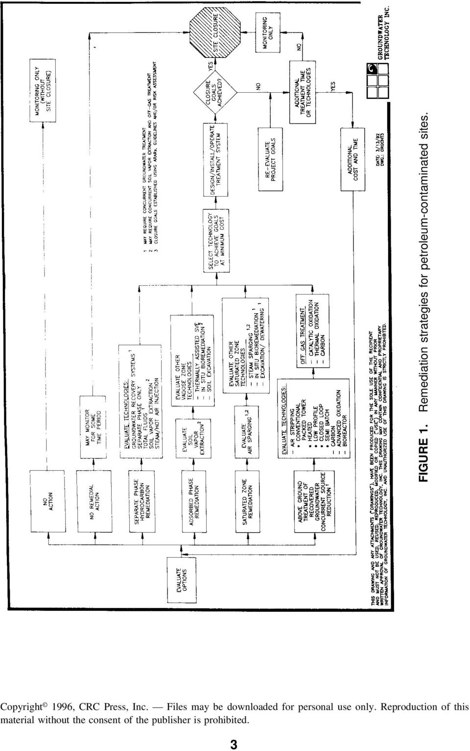
2 technologies are often selected because they are familiar and not because they are the most applicable or cost-effective for a given site. Figure 1 summarizes the applicable technologies for the remediation of soil and groundwater contaminated with petroleum hydrocarbon and presents a generalized hierarchy for selecting multiple technologies. These technologies may be subdivided into 1. Liquid-phase hydrocarbon (LPH) removal technologies 2. Vadose zone treatment technologies 3. Saturated zone treatment technologies 4. Treatment technologies for recovered groundwater 5. Off-gas treatment technologies Selection of technologies within these categories is based on (1) technology applicability; (2) regulatory acceptance; (3) cost; and (4) treatment time. Technology applicability is dependent on the effectiveness of a technology for treating specific contaminants for existing site conditions (i.e., soil type, aquifer characteristics, etc.). Different technologies have varying constraints, which are described in further detail in Section III. Technology applicability is also dependent on the availability of the technology, the implementability of the technology for the specific site conditions, and whether the technology is readily available (i.e., emerging, developing, or proven). Regulatory acceptance must also be considered based on the degree of difficulty that the user anticipates when obtaining a permit from local or state regulatory agencies to implement the technology. Treatment time and cost must also be considered so that technologies can be selected that achieve closure goals at minimum cost and time. Potential liabilities associated with site contamination and regulatory compliance may also impact the selection of remediation strategies. The purpose of a decision framework is to provide a consistent and technically sound approach for selecting appropriate remediation strategies for the clean up of contaminated sites. This approach is necessary to optimize technology selection based on closure requirements and other project goals and to document the technology selection process. The American Petroleum Institute (API) developed a petroleum decision framework to facilitate decision making for investigation and cleanup of petroleum release to soils and groundwater (API, 1990). Menu functions include initial response abatement, site assessment, and site remediation. The U.S. Department of Energy Pacific Northwest Laboratories (Kelly et al., 1992) has also developed a Remedial Action Assessment System (RAAS) that provides information about remedial action technologies. RAAS allows the user to assess remediation technologies through descriptive information and application data and provides technology applicability information and regulatory constraints. The RAAS system 2

3 FIGURE 1. Remediation strategies for petroleum-contaminated sites. 3
4 runs on a Macintosh II and uses ORACLE database software. EPA s Risk Reduction Engineering Laboratory (RREL) also has a treatability database that includes 33 treatment technologies, 13 aqueous matrices, and 5 solid matrices (Haztech News, May 1992). The database is accessible through the Alternative Treatment Technology Information Center (ATTIC), which is EPA s database on hazardous waste-treatment technologies. EPA has also designed the Cost of Remediation Model (CORA) as an expert system for developing remediation cost information. II. TECHNOLOGY DESCRIPTIONS To understand the decision framework for technology selection, it is important to understand the general principles of applicable technologies for the remediation of petroleum hydrocarbon-contaminated sites. Some information about technologies for treating petroleum-hydrocarbon contamination was compiled by Environmental Solutions, Inc. (March 1990) for the Western States Petroleum Institute (WSPI). The WSPI manual provides technology descriptions and an overview of the technology screening process. EPA has also compiled technology descriptions for processes that treat contaminated soils and sludges (USEPA, 1988). Emerging and developing technologies being investigated in EPA s Superfund Innovative Treatment Evaluation Program (SITE) have also been described (USEPA, 1991). A. Liquid-phase Hydrocarbon Removal Conventional LPH recovery is the recovery of LPH from the groundwater and it addresses the most concentrated phase of contamination and the source for vadoseand saturate-zone contamination. LPH recovery is often considered a short-term measure to prevent further impact to soil and groundwater and serves as a supplemental technology to other in situ remediation techniques. Generally speaking, as the viscosity of a given LPH increases and aquifer grain size/permeability decreases, residual saturation increases, resulting in less mobile LPH available for removal. It has also been shown that the position of the water table at the time of the loss as well as the thickness and areal extent of LNAPL accumulation have a direct impact on the amount of LPH removed. Low water-table conditions with minimal fluctuations offer the best conditions for product accumulation and removal on the groundwater surface. LPH recovery methods include: Total fluid extraction. This method involves direct removal of LPH and water as a combined waste stream. Once product and water are removed from the subsurface, an oil/water separator is used to remove the LPH from the water. Total fluid extraction is most applicable for small accumulations of LPH with low (T <1000 gpd/ft) to medium (T = 1000 gpd/ft to 25,000 4
 as an expert system for developing remediation cost information. II.")
5 gpd/ft) aquifer transmissivity. Manifolded well points or multiple wells with ejector pumps are commonly used. Dual pump recovery. Under this type of system, two separate pumps are used. One pump is deployed to depress the water table by pumping water, with the other pump used to pump product that has accumulated in the water table depression induced by the water pump. With this type of system, the LPH and water remain separated as they are removed from the subsurface. Many types of dual pump systems are available for different diameter recovery wells or trench sumps. Dual pump recovery is best suited for larger, thick accumulations of LPH with medium (T = 1000 gpd/ft to 25,000 gpd/ft) to high (T >25,000 gpd/ft) aquifer transmissivity to enable areal depression of the water table for product recovery. Passive recovery. When a less active LPH recovery system is warranted, skimming bailers or a Filter Bucket device may be deployed in wells or trenches to passively recover product. With these systems, LPH is gradually accumulated in the device for periodic removal manually. Passive recovery is most useful for small quantities of LPH in discrete, localized accumulations. The bailers and Filter Buckets that can be used for this type of LPH recovery are the least expensive and easiest to deploy of all the LPH recovery systems. Thermally assisted LPH removal involves injecting heat into the subsurface to decrease the viscosity of LPH. This decreases the residual saturation and thereby increases the amount of mobile LPH available for removal. Typically, heat is provided at locations throughout the LPH plume, and the flow of heat is controlled by a soil vapor extraction (SVE) system and/or by groundwater pumping. LPH recovery is otherwise performed in a manner similar to conventional LPH recovery. Heat may be supplied to the subsurface via hot air injection, steam injection, or radio frequency (RF) heating. B. Vadose-Zone Treatment Technologies Soil vapor extraction removes volatile organic compounds (VOCs) such as benzene, toluene, ethylbenzene, and xylenes (BTEX) from unsaturated (vadose-zone) soils by inducing air flow through contaminated areas. SVE is typically performed by applying a vacuum to vertical vapor extraction wells screened through the level of soil contamination, using a vacuum blower. The resulting pressure gradient causes the soil gas to migrate through the soil pores toward the vapor extraction wells. VOCs are volatilized and transported out of the subsurface by the migrating soil gas. Johnson et al. (1990) summarized the general approach to the design, operation, and monitoring of in situ SVE systems. Additional information about 5

6 the use of SVE in remediation vadose-zone contamination has been described by Brown and Bass (1991). Thermally assisted SVE involves the injection of heat into the vadose zone to improve the performance of soil venting by increasing the vapor pressure of the contaminants to be removed. Typically, heat is provided at locations surrounding the vapor extraction wells, and the heat migrates inward along with the soil gas. Operation of the vent system is otherwise identical to conventional soil venting. Heat can be injected by one of three methods: Hot air injection. Air is heated and injected under pressure into the subsurface to increase the temperature. If catalytic or thermal oxidation of offgas is being used, most of the hot exhaust gas can be injected to heat the subsurface. Steam injection. The heat content of steam is much greater than that of air at the same temperature because of the latent heat released when steam condenses. Steam injected into the subsurface will create some groundwater mounding as the steam condenses, so groundwater pumping ordinarily will be required. RF heating. A radio frequency transmitting antenna is placed in a well and radio waves are directed into the zone of contamination. Although the price per BTU is higher than for steam or hot air injection (because it is generated electrically), the heat can be directed more evenly and more precisely. This is an emerging technology that has been used less frequently than hot air or steam injection. Vented in situ percolation is a process in which chemicals that are present in the unsaturated zone can be treated by aerobic biodegradation. Naturally occurring bacteria are stimulated to degrade hydrocarbons by adding oxygen and inorganic nutrients. Oxygen is supplied to the vadose zone by applying a vacuum-inducing air flow through the soil. Inorganic nutrients in the form of ammonia and phosphate are then percolated through the soil to stimulate biodegradation. Volatile hydrocarbons are removed primarily by the physical action of venting, whereas adsorbed and heavier hydrocarbon components will be biodegraded. The extent of biodegradation can be estimated by monitoring the carbon dioxide in the vented gases. Inorganic nutrients are usually added periodically to the subsurface through the vent-system piping. Water (either treated recovered groundwater or fresh water) is regularly amended with nutrients and injected under supplied or gravity pressure to the vent system with the blower off. Alternatively, the nutrients can be infiltrated through horizontal slotted piping laid at intervals on the surface or in trenches just above the depth of contamination. Excavation and disposal or treatment of vadose-zone soils is generally the option of last resort. The in situ vadose-zone technologies previously described 6

7 offer the advantages of being relatively inexpensive, versatile, and may be able to achieve site closure within a desired time period. However, in situ technologies may require long-term monitoring to demonstrate effectiveness and are not implementable at certain sites. For example, very tight soils or soils containing nonvolatile and nonbiodegradable contaminants may not be amenable to the in situ technologies described previously. In such cases, soil excavation with disposal or on-site treatment may be the only alternative to remove sorbed-phase contamination from unsaturated soil. Although expensive, excavation does provide a permanent solution by rapidly removing the contaminant source. Once removed, contaminated soil can be transported to an off-site disposal facility or treated on site. Treatment technologies for excavated soil include (1) beneficial reuse (asphalt incorporation and construction reuse); (2) solidification/stabilization (chemical or biological stabilization processes); (3) chemical extraction (heap leaching and liquid/solid contactors); (4) volatilization (surface spreading, soil pile aeration, soil shredding); (5) chemical treatment (peroxide spraying); (6) bioremediation (biopiles, slurry reactors); and (7) low-temperature thermal treatment (low-temperature thermal stripping or soil roasting). High-temperature thermal treatment such as incineration, pyrolysis, and vitrification technologies are generally not considered for treating petroleum hydrocarbon-contaminated soil because of their high costs. C. Saturated-Zone Treatment Technologies Air sparging involves forcing air under pressure into the contaminated saturated zone. Sparging creates air-filled porosity in the saturated zone that facilitates direct volatilization of contaminants from saturated soil and removes volatile organics from groundwater, acting in much the same way as an air stripper. Sparging also creates turbulence and improves mixing in the saturated zone, which increases the transfer of contaminants from saturated soils to groundwater. Sparging enhances natural biodegradation of some contaminants by maintaining high dissolved-oxygen levels. Sparging is generally implemented in conjunction with soil-vapor extraction so that the contaminated sparge air is collected to prevent potential migration to nearby basements or to prevent contaminating the vadose zone. Groundwater recovery and treatment may also be conducted to provide hydraulic control of the contaminant plume during sparging. The use of air sparging for treating volatile contaminants in the saturated zone has been discussed in further detail by Brown (1991). Steam sparging (sometimes called steam injection ) involves the forced injection of pressurized air and steam into the saturated zone, generally at a point just below the vertical extent of contamination. All physical mechanisms for contamination removal are enhanced because increased temperature increases the vapor 7

8 pressure, Henry s Law constant, and (usually) the solubility of the contaminants. However, bioremediation would usually be retarded by the high temperatures. Steam sparging should be considered whenever rapid remediation is mandatory or when the saturated zone is contaminated with nonbiodegradable or semivolatile compounds. Steam sparging should always be performed in conjunction with soilvapor extraction and groundwater pumping for recovery of sparged contaminants and to maintain hydraulic control of the contaminant plume. In situ bioremediation is a process in which petroleum products are degraded in situ by naturally occurring bacteria by the introduction of inorganic nutrients (nitrogen and phosphorus) and oxygen into the groundwater. The process treats both dissolved and adsorbed hydrocarbons. The process can be conducted with or without hydraulic control, depending on state requirements. As in bioremediation of the vadose zone, oxygen and nutrients are required to promote aerobic biodegradation. Air sparging may be used to introduce oxygen to the saturated zone and is subject to the same limitations and design requirements as described earlier. Hydrogen peroxide, which hydrolyzes to form dissolved oxygen in the groundwater, may also be used. However, the stability of peroxide in site soil and groundwater influences its effectiveness. If peroxide hydrolyzes too rapidly, oxygen will only be supplied to the groundwater for a short distance away from the injection point. A laboratory measurement of peroxide stability in site materials is therefore recommended to estimate effectiveness. Inorganic nutrients and peroxide are usually added to the subsurface through a groundwater reinjection system. Groundwater is recovered downgradient of the contaminated area, treated, amended with nutrients, and reinjected upgradient of the contaminant plume. If hydraulic control is required, only a portion of the recovered groundwater is reinjected. The nutrient-amended groundwater can be reinjected through vertical points (e.g., monitoring wells) or through horizontal slotted piping in trenching. The goal is to inject the nutrient-amended groundwater at or near the groundwater table. Nutrients will be retarded by soil adsorption if the solution is delivered in the vadose zone. Further information about the use of in situ bioremediation of petroleum-contaminated soil can be found in review articles by Hicks and Brown (1990), Arvin et al. (1988), and Litchfield and Clark (1973). Excavation and disposal or treatment of saturated-zone soil is again the option of last resort. Although in situ treatment of saturated-zone soil is generally the most cost-effective method for removing contamination from this matrix, site or contaminant characteristics or expedited remediation objectives may require that saturated-soil excavation be considered for sorbed-phase contamination in the saturated zone. In addition to the technologies described earlier for excavated soil, dewatering and treatment would be needed to meet regulatory-based discharge levels. Soil excavation and dewatering are often used in underground storage-tank removal operations where the excavation pit intersects the groundwater table. 8

9 D. Groundwater Recovery and Treatment Groundwater treatment consists of (1) groundwater withdrawal from the subsurface and (2) above-ground treatment of recovered groundwater. Additionally, groundwater containment technologies may be used to gain hydraulic control of contaminant plumes. Groundwater pumping is primarily used as a containment strategy. It has been shown to enhance remediation but is effective as a sole remediation technique for only very soluble contaminants such as MTBE. Groundwater pumping/containment technologies can be considered either active or passive. Active methods include direct containment and removal of contaminated groundwater using recovery wells, well points, or interceptor trenches/ barriers. Passive methods redirect the flow of groundwater or confine the affected groundwater to a specific area using slurry walls, sheet piles, and impermeable caps. The use of a given method depends on site hydrogeologic conditions and remediation goals. Active containment methods include: Recovery wells are used where the soil is fairly permeable, especially with depth as in clean sands or coarser granular soils, and where the saturated thickness is sufficient to submerge the well screen and pump as the water table is lowered under pumping conditions. Recovery wells with individual submersible pumps can be installed within or on the perimeter of the zone to be contained. Well points are constructed of small well screens less than 4 in in diameter and less than 5 ft long. Individual well points are usually attached to a common header pipe and connected to a well-point pump. They are used in fairly cohesive and fine-grained soils and are very useful where the desired drawdown depth is only a short distance above an impermeable layer. Where there is adequate saturated thickness and a higher pumping rate, deeper recovery wells are better suited. Interceptor trenches are constructed by excavating a continuous slot in the subsurface and backfilling the excavation with a permeable material to permit drainage. More sophisticated methods include the installation of a continuous, perforated drainage pipe in the bottom of the trench and/or vertical sumps where the collected water is pumped out for treatment/ disposal. Interceptor trenches need not fully penetrate the saturated zone of concern and they provide a continuous positive cutoff of groundwater where contaminant breakthrough is not likely to occur. The use of impermeable barriers/liners on the downgradient sides of trenches can also enhance recovery and containment of impacted groundwater. They are best suited for low-permeability soils with a shallow depth to groundwater to minimize 9

10 construction constraints and where treatment/disposal of excavated soils will not present regulatory problems. Passive containment methods include: Slurry walls, also known as grout curtains, are cutoff trenches that are backfilled with impermeable material such as bentonite. They can serve as an adequate cutoff to contaminant migration if (1) they are installed so that they can be tied into an impermeable base that is not too deep; (2) they do not develop cracks or gaps through which contaminant breakthrough will occur; and (3) if there is not too much pressure buildup on the upgradient side that would force the contaminants to skirt around the perimeter of the wall. They are best suited for relatively low-permeability conditions in shallow aquifers. Sheet piles are commonly fashioned as steel plates driven into the subgrade below the water table and secured into an impermeable base at depth. For these devices to be feasible, the impermeable base must not be too deep. Also, because the sheet piles are placed in an overlapping manner adjacent to one another, there are gaps that can allow contaminants to migrate through. They are best suited to shallow water-table conditions with low-tomoderate permeability. The most appropriate application of sheet walls is developing flow barriers and containment cells for short-term dewatering projects. Impermeable caps provide a means for cutoff or diversion of vertical recharge and therefore serve to reduce horizontal groundwater flow and contaminant transport. They can be very costly to construct and are only appropriate for large-scale applications. Groundwater treatment technologies for recovered groundwater containing petroleum-hydrocarbon contamination generally consist of either separation technologies such as (1) liquid-phase carbon adsorption and (2) air stripping, or destructive technologies such as (3) advanced oxidation and (4) bioreactors. Separation technologies are generally the most cost-effective approach for treating recovered groundwater containing petroleum-hydrocarbon contamination, although off-gas treatment requirements for air strippers and carbon disposal costs may add significantly to total treatment costs. Advanced oxidation and bioreactors should be considered for treating recovered groundwater that is cocontaminated with organics that are not amenable to air stripping and carbon-adsorption treatment. Advanced oxidation is effective for treating aromatic compounds such as BTEX as well as water-soluble contaminants (such as phenols) that cannot be removed efficiently by air stripping or activated carbon. Bioreactors can also effectively treat BTEX and soluble compounds such as phenol, alcohols, and ketones. 10
 if there is not too much pressure buildup on the upgradient side that would force the contaminants to skirt around the perimeter of the wall.")
11 Liquid phase adsorption is the accumulation of dissolved chemicals (adsorbate) from liquid phase onto a surface of a solid (adsorbent). The adsorptive properties of activated carbon are attributable mainly to its highly porous structure and resulting large surface area. Contaminated groundwater is generally treated by passing it sequentially through two vessels containing activated carbon until breakthrough is observed in the first carbon unit. Review articles on the use of activated carbon for the removal of aqueous-phase contaminants have been prepared by Speth (1990) and Clark and Adams (1991b). Air stripping is the process of removing volatile contaminants from a liquid stream by contacting the liquid with air. The air and liquid flows are generally countercurrent. The effectiveness of contaminant removal improves with increasing values of the Henry s Law constant of the contaminant, the air-to-water ratio, the stripping factor (equal to Henry s Law constant multiplied by the air-to-water ratio), and the size of the air stripper. A variety of proven air stripper designs are available: conventional packed tower, countercurrent aeration trays, venturi air injection systems, and sequential air diffuser chambers. Emerging air stripper designs include (1) heated air strippers that recycle waste heat from off-gas treatment units to enhance removal of less volatile compounds such as methyl tertiary butyl ether (MTBE) and (2) closed-loop stripping to prevent iron or calcium fouling of air-stripper packing. Additional information about the use of air stripping for the removal of aqueous volatile compounds can be found in Clark and Adams (1991a) and Cummins and Westrick (1990). Advanced oxidation processes destroy aqueous contaminants by reaction with free hydroxyl radicals. The hydroxyl radicals are typically produced using combinations of ultraviolet radiation, ozone, and/or hydrogen peroxide. Advanced oxidation can be used for treatment of water streams contaminated with aromatic compounds such as BTEX, double-bonded organic compounds such as trichloroethylene (TCE) and tetrachloroethylene (PCE), and other compounds, including sulfide, cyanide, chlorophenols, polychlorinated biphenyls (PCBs), polynuclear aromatic hydrocarbons (PAHs), and some pesticides. Advanced oxidation, however, is less cost-effective in treating saturated organic compounds such as trichloroethane (TCA), dichloroethane (DCA), MBTE, alcohols, ketones, and saturated petroleum hydrocarbons. Review articles on the use of advanced oxidation for treating aqueous organic contaminants have been prepared by Roy (1990) and Peyton (1990). Bioreactors are used to degrade many organic compounds found in groundwater using bacteria in a reactor. Recovered groundwater is amended with inorganic nutrients (nitrogen and phosphate) and fed into the reactor tank. Oxygen is supplied through air diffusers at the bottom of the bioreactor. Bioreactors can provide cost-effective treatment of BTEX when carbon loading is very high or when off-gas treatment is necessary. Removal rates can be 11
 and Clark and Adams (1991b).")
12 greater than 99% with proper design. A laboratory treatability test is recommended to properly size the reactor. Two types of bioreactors are Fixed film bioreactors. Hydrocarbon-degrading bacteria attach to a solid support media in the reactor and form a biofilm. This attachment allows the bacterial biomass to be retained in the reactor. The biofilm is stable to a wide range of fluctuating contaminant concentrations and mixtures encountered in groundwater treatment. The biofilm can withstand sudden high-shock loadings and remain stable in the presence of very low-contaminant concentrations. Suspended growth reactors. Bacteria grow in suspension within the reactor and are washed out with the effluent. These reactors are often used for waste streams with high-carbon loading. E. Offgas Treatment Technologies Offgas treatment may be required from air-stripping units or soil-vapor extraction systems to limit hydrocarbon discharge to the atmosphere. Requirements vary between states. Offgas treatment of hydrocarbon can be achieved using (1) vaporphase adsorption; (2) catalytic oxidation; or (3) thermal-oxidation treatment. The relative costs of these technologies for treating hydrocarbon vapors have been reviewed by Kroopnick (1991). Vapor phase adsorption is the accumulation of a particular chemical from an offgas stream onto the surface of a solid. Contaminated offgas is generally treated by passing it sequentially through two vessels containing activated carbon until breakthrough is observed in the first carbon unit. Because vapor-phase carbon typically adsorbs five to 20 times more of a given contaminant per pound than liquid-phase carbon, air stripping with carbon treatment of offgas is often more cost-effective than liquid-phase carbon treatment alone. Catalytic oxidation destroys organic contaminants in vapor streams by reacting with atmospheric oxygen on a hot catalytic surface to produce carbon dioxide and water. The catalyst is heated electrically in units with a treatment capacity of less than 500 scfm and with propane or methane in larger units. Thermal oxidation destroys organic contaminants in vapor streams by reacting with atmospheric oxygen to produce carbon dioxide and water. Combustion takes place in a furnace that is usually fueled with methane or propane. Thermal oxidation units have lower initial costs than catalytic oxidation units but are usually more expensive to operation because of higher fuel requirements. 12

13 III. THE REMEDIATION DECISION FRAMEWORK To select appropriate technologies the following information is needed: Applicability of technology to site contaminants: Contaminant properties can often provide a general indication about the applicability of treatment technologies to remove such contaminants from environmental media. For example, contaminants in the vadose zone that exhibit a vapor pressure greater than 1 mmhg are generally amenable to soil-vapor extraction. Sorbed-phase contaminants in the saturated zone can usually be sparged if they have a dimensionless Henry s Law constant greater than 0.1 and a vapor pressure greater than 1 mmhg. Chemicals with a dimensionless Henry s constant greater than 0.1 can routinely be removed from recovered groundwater by air stripping. Other contaminant properties such as solubility, absorbability, and biodegradability indicate applicable treatment technologies. Variations in technology design: Technologies can be designed and implemented in various configurations to optimize treatment effectiveness and project goals. Soil-vapor extraction, for example, can be enhanced by concurrent groundwater pumping to expose contaminants at the groundwater capillary fringe. Horizontal vapor-extraction wells may also be considered when the depth to groundwater is less than 5 ft to provide more effective airflow in the vadose zone. Surface sealing may also enhance soil-vapor extraction. Air sparging can be conducted with or without concurrent soil venting and/or groundwater pumping. There are also many different types of air stripper designs with and without offgas treatment. Selection of the best technology design variation is dependent on many factors including site characteristics, design flow, regulatory requirements, and treatment objectives. Site characteristics: The applicability of treatment technologies is highly dependent on site characteristics. Both soil venting and sparging technologies require fairly permeable formations to allow sufficient airflow through the subsurface. The radius-of-influence (ROI) for vent or sparge points must generally be greater than 10 ft to provide a cost-effective remediation system design. Selection of LPH and groundwater recovery systems is dependent on both the transmissivity of the aquifer and the depth to groundwater. Soil characteristics will also impact the ability to augment the growth of naturally occurring microorganisms through the addition of nutrients and oxygen. Regulatory acceptance of technology and required permits: Different state regulatory agencies have varying requirements for groundwater withdrawal, groundwater discharge, and air discharges. The need for offgas treatment from 13

14 an air-stripping unit, for example, may make that technology cost-prohibitive when compared with aqueous carbon adsorption. Injection of nutrients into groundwater to augment naturally occurring microorganisms may not be permitted by some state agencies because of the concern about nitrates in groundwater. Technology availability: Although some technologies such as air stripping, carbon adsorption, and soil venting are readily available and widely used, others are just beginning to be used for remediation of hydrocarbon-contaminated sites. Air sparging has gained much acceptance over the past few years and steam sparging is being increasingly considered for treatment of less volatile contaminants or where expedited treatment is desired. Emerging technologies such as closed-loop stripping may also be applicable where offgas treatment is required and chemical or biological fouling is a problem. The availability and proven effectiveness of such technologies should be considered during the technology selection process. Treatment time objectives: Property transfer deadlines sometimes require expedited remediation, usually at higher costs. Soil contamination in either the vadose or saturated zones can be expedited by hot air or steam injection that results in a more favorable Henry s Law constant and subsequent volatilization and removal of contaminants from the subsurface. Steam stripping may also be used to enhance and expedite volatilization of contaminants from recovered groundwater. In extreme cases, soil excavation with subsequent above-ground treatment or disposal may be considered to remove sorbedphase contamination. Project life-cycle costs: Project life-cycle costs consist of all expenses that are incurred for site assessment and remediation over a project s lifetime. These costs include site assessment and remediation, site engineering and design, capital costs, operation and maintenance requirements, monitoring, and project management. The remediation system having the lowest possible present value cost, which achieves project objectives in terms of both closure goals and treatment time, should be selected. Obviously, capital costs must be carefully weighed against the estimated treatment time required to achieve closure. Administrative and potential litigation costs should also be considered in selecting the remediation strategy. Decision analysis in remediation planning is discussed in further detail by Angell (1990). These considerations are interactive and complex. Therefore, a decision framework provides a methodology for reviewing the various contaminant, site, regulatory, cost, and time constraints that impact technology selection. Given the multitude of cost, time, contaminant, site, and technology con- 14

15 FIGURE 2. Decision framework for remediation technologies. straints, a decision framework provides a structured progression of decision points consisting of technology or site applicability criteria. The outcome of these decision points directs the user to subsequent decision points and 15

16 ultimately aids in selecting applicable technologies for contaminated environmental media. Figure 2 summarizes the general decision-making process for selecting remediation technologies at sites contaminated with petroleum hydrocarbon. The hierarchy considers LPH-removal technologies first because they address the most concentrated source of contamination. In situ vadose- and saturated-zone technologies are then considered, followed by groundwater pump and treatment technologies, which do not generally address contaminant source removal directly and are therefore less desirable. Figure 2 also emphasizes the importance of site characterization and establishing closure goals so that technology applicability and remediation criteria can be adequately assessed. For each of the technology boxes shown in Figure 2, additional detailed decision points are needed to determine applicable technologies for LPH, vadose-zone, saturated-zone, groundwater pump and treatment, and offgas technologies. Decision-making criteria for several technologies are illustrated in Table 1. These criteria are then placed into a decision framework for selecting the most appropriate technologies based on site conditions, contaminant properties, and desired treatment time. A detailed decision framework for selecting groundwater withdrawal systems is shown in Figure 3. The decision points include: Does the aquifer exhibit low (T < 1000 gpd/ft), medium (1000 gpd/ft < T < 25,000 gpd/ft), or high (T > 25,000 gpd/ft) transmissivity? Is the depth to water greater than or less than 10 ft? Is the saturated-zone thickness greater than or less than 10 ft? Based on these decision points, one of nine different groundwater recovery systems is selected as being the most applicable for the associated site conditions. Figure 4 provides another example of the decision framework for soil-vapor extraction. The decision points include: Is LPH < 6 in to 2 ft or is the vadose zone contaminated? Is expedited remediation desired? Is the depth to water greater than about 3 ft? Do the contaminants exhibit a vapor pressure > 1 mmhg? Does the formation exhibit a soil-vapor extraction ROI greater than about 10 ft? Is offgas treatment required? 16

17 TABLE 1 Technology Applicability Soil type and saturated Technology Applicability zone characteristics Variations Cost Permits LPH recovery All lighter-than-water Works better with more Total fluid extraction, Variable Groundwater discharge, LPH withdrawal petrochemicals except for the permeable soils passive bailers, dual pump product storage, and most viscous fuel and lube oils recovery, recovery wells, possibly, groundwater thermally assisted LPH withdrawal recovery, mop and disk skimmers Vadose zone LPH less than about 0.5 ft, Permeable soils, Thermally assisted venting, Low Air discharge permit may Soil vapor contaminants with Vp >1 mm ROI >10 ft horizontal venting, surface be required extraction Hg (BTEX, gasoline, MTBE, depth-to-water greater sealing, passive vent PCE, TCE, TCA, mineral spirits, than 3 ft points, closed loop venting, MeOH, Acetone, MEK, etc.) concurrent groundwater pumping for VOCs in capillary fringe In situ percolation Any aerobically biodegradable Works better in permeable Oxygen and nutrients need Low to Air discharge permit may (bioremediation) chemical in the vadose zone soils; depth-to-water to be supplied to the moderate be required when soil greater than 3 ft subsurface venting used to provide oxygen Excavation All soils and contaminants All soil types Dewatering may be used to High On-site treatment of expose soils in capillary excavated soil may require fringe permitting Saturated zone Contaminants in saturated Hydraulic conductivity Hot air, steam, and cyclic Low Air discharge permit; water Sparging zone with K H >0.1 and Vp > >10 5 cm/sec sparging; concurrent discharge if concurrent 1 mmhg; Contaminants: (silty sand or better); At groundwater pumping groundwater pumping BTEX, gasoline, PCE, TCE, least 5 ft of saturated TCA, mineral spirits thickness In situ Any biodegradable chemical in Nutrients are transported Oxygen supplied by Moderate to Water discharge for nutrient bioremediation the saturated zone; inhibited better in more permeable sparging or peroxide high injection, air discharge if by ph extremes, heavy metals, soil addition; nutrient addition performed with sparging/ and toxic chemicals with groundwater recovery venting and reinjection Excavation All soils and contaminants All soil types Dewatering needed, Very high Permits for dewatering groundwater containment operations may be used (slurry walls, sheet piles) 17

18 TABLE 1 (continued) Technology Applicability Soil type and saturated Technology Applicability zone characteristics Variations Cost Permits Groundwater Uses: (1) LPH recovery, Transmissivity, depth-to- Recovery wells, well points, Variable Well installation, recovery and (2) provides hydraulic control water and saturated-zone interceptor trenches groundwater withdrawal treatment of contaminant plume, (3) pump thickness determine and groundwater discharge Groundwater and treatment technologies optimal strategy recovery Liquid-phase Removal of compounds with See groundwater recovery High pressure (75 to 150 Low to high Water discharge carbon low solubility/high adsorptivity psi) and low pressure (12 depending on to 15 psi) contaminant loading Air stripping Compounds with K H >0.1; See groundwater recovery Packed towers, low profile, Low, if no Air and water discharge contaminants with K H between heated and closed loop air offgas permits may require an stripping; offgas treatment treatment air:water ratio >100 may be required required Advanced Most effective on sulfide See groundwater recovery Hydroxy/radicals produced Moderate to Water discharge permit oxidation cyanide, double-bonded by combinations of UV, high organics (PCE, TCE), BTEX, ozone, and peroxide phenols chlorophenols, PCBs, PAHs, some pesticides Bioreactors Any biodegradable compound See groundwater recovery Fixed film and suspended Moderate to Water discharge permits growth reactors high Offgas Treatment Adsorptive capacity generally NA Pretreatment dehumidification; Moderate Air discharge permit Vapor-phase increases with increasing on-site regeneration carbon molecular weight Catalytic Conventional units can treat all NA Some units can treat Moderate to Air discharge permit oxidation compounds containing carbon, chlorinated compounds, high hydrogen, and oxygen. exhaust gas scrubbing may Concentrations should not be required exceed about 20% of the LEL Thermal oxidation Compounds containing NA Exhaust gas scrubbing may Moderate to Air discharge permit carbon, hydrogen, and oxygen; be required high usually not amenable to halogen-containing compounds Abbreviations: NA, Not applicable; LEL, Lower explosion limit; ROI, Radius-of-influence; LHP, Liquid-phase hydrocarbon. 18
 and low pressure (12 depending on to 15 psi) contaminant loading Air stripping Compounds")
19 FIGURE 3. Groundwater pumping and treatment: Groundwater recovery (H). 19

20 FIGURE 4. Vadose-zone treatment: Soil-vapor extraction (A, B, D). 20

21 These decision points guide the user to different technology options consisting of a variety of soil vapor extraction configurations. Alternatively, contamination or site properties may not be amenable to soil vapor extraction in which case, bioremediation or soil excavation may be considered. Additional decision frameworks for LPH recovery, in situ vadose-zone bioremediation, saturated-zone sparging, saturated-zone bioremediation, and treatment of recovered groundwater using either carbon, air stripping, or advanced oxidation, have also been developed. In addition to technology applicability, the selection of remediation technologies must also consider additional factors: cost, desired treatment time, technology availability, and regulatory acceptance. When all these criteria are placed into a decision framework, remediation technologies can be selected in a systematic and logical manner to achieve project goals. The decision framework also documents the technology selection process for potential future needs. The decision framework transforms a complex and multifaceted problem into a series of discrete and understandable decision points that can be used to select the most desirable remediation strategy to achieve site closure. IV. TECHNOLOGY INTEGRATION Remediation technologies can work together to complement their effectiveness in degrading or removing site contamination. Figure 5 illustrates the interaction between a number of technologies that are typically used at petroleum hydrocarbon-contaminated sites. Although soil-vapor extraction is primarily directed at removing volatiles from the vadose zone, it also provides oxygen to enhance vadose-zone bioremediation, removes sparged air, and decreases adsorbed-phase contamination. Air sparging directly volatilizes sorbed-phase contamination in the saturated zone while additionally providing oxygen for saturated-zone bioremediation. Groundwater pump and treatment technology removes aqueous-phase contamination and provides hydraulic control during sparging. These interactions enhance the effectiveness of the individual technologies thereby providing more effective remediation. The decision framework presented herein is a valuable tool in selecting technologies for the remediation of sites contaminated with petroleum hydrocarbon by providing a systematic process to formulate defensible solutions to complex problems. 21
22 FIGURE 5. System integration. 22
23 REFERENCES American Petroleum Institute Petroleum Release Decision Framework. Angell, K. Selection Methodology for Environmental Remediation Planning. Presented at Mid- Atlantic Environmental Exposition, Baltimore, MD. (April 9 11, 1990). Arvin, E., Godsy, E. M., Grbic-Galic, D., and Jensen, B., Microbial Degradation of Oil and Creosote Related Aromatic Compounds under Aerobic and Anaerobic Conditions. International Conference on Physicochemical and Biological Detoxification of Hazardous Wastes, Atlantic City, NJ. (May 3 5, 1988). Brown, R. A. and Fraxedas, R., Air-Sparging Extending Volatilization to Contaminated Aquifers. Presented at the Symposium on Soil Venting, Robert S. Kerr Environmental Research Laboratory, Houston, TX. (April 29 May 1, 1991). Brown, R. A. and Davis Bass: Use of Aeration in Environmental Clean-ups. Presented at the Mid- Atlantic Environmental Expo, Baltimore, MD. (April 9 11, 1991). Clark, R. M. and Adams, J. Q., 1991a. EPA s Drinking Water and Groundwater Remediation Cost Evaluation: Air Stripping. Chelsea, MI, Lewis Publishers. Clark, M. and Adams, J. Q., 1991b. EPA s Drinking Water and Groundwater Remediation Cost Evaluation: Granular Activated Carbon. Chelsea, MI, Lewis Publishers. Cummins, M. D. and Westrick, J. W., Treatment technologies and costs for removing volatile organic compounds from water: aeration. In: Significance and Treatment of Volatile Organic Compounds in Water Supplies. (N. M. Ram, R. F. Christman, and K. P. Cantor, Eds.) Chelsea, MI, Lewis Publishers. Environmental Solutions, Inc., Irvine, California, prepared for Western States Petroleum Association, March HazTech News, Vol. 7, No. 10, p. 78 (May 14, 1992). Hicks, R. J. and Brown, R. A., In-Situ Bioremediation of Petroleum Hydrocarbons. Presented at the Water Pollution Control Federation Annual Conference, Washington, DC (October 7 11, 1990). Johnson, P. C., Stanley, C. C., Kemblowski, M. W., Byers, D. L., and Colthart, J. D., A practical approach to the design, operation, and monitoring of in situ soil-venting systems. Groundwater Monitoring Review, Spring Issue. Kelly, A., Pennock, S. J., Bohn, and White, M. K., U.S. Department of Energy Pacific Northwest Laboratories, Expert Software that Matches Remediation Site and Strategy. Remediation, pp , (Spring, 1992). Kroopnick, P. M., Life-cycle costs for the treatment of hydrocarbon vapor extracted during soil venting. In: Proceedings: Petroleum Hydrocarbons and Organic Chemicals in Groundwater, National Water Well Association, Houston, TX (November 1991). Litchfield, J. H. and Clark, L. C., Final report on bacterial activity in groundwater containing petroleum products. Project OS 21.1, Committee on Environmental Affairs, American Petroleum Institute (API Publication No. 4211, November 12, 1973). Peyton, G. R Oxidative treatment methods for removal of organic compounds from drinking water supplies. In: Significance and Treatment of Volatile Organic Compounds in Water Supplies. (N. M. Ram, R. F. Christman, and K. P. Cantor, Eds.). Chelsea, MI, Lewis Publishers. Roy, K. A UV-Oxidation Technology. Hazmat World pp Speth, T. F Removal of volatile organic compounds from drinking water by adsorption. In: Significance and Treatment of Volatile Organic Compounds in Water Supplies. (N. M. Ram, R. F. Christman, and K. P. Cantor, Eds.) Chelsea, MI, Lewis Publishers. USEPA. Cost of Remedial Action (CORA) Model. Contact: USEPA: The Superfund Innovative Technology Evaluation Program (SITE). Technology Profiles, 4th ed. EPA/540/5 91/008 (November 1991). 23
24 USEPA: Technology Screening Guide for Treatment of CERCLA Soils and Sludges. EPA/540/2 88/004 (September 1988). USEPA: Alternative treatment technology information center (ATTIC). Research and Development (RD-681). EPA/600/M-91/049 (November 1991). 24
CHAPTER 7: REMEDIATION TECHNOLOGIES FOR CONTAMINATED GROUNDWATER
 CHAPTER 7: REMEDIATION TECHNOLOGIES FOR CONTAMINATED GROUNDWATER There are a number of technologies that are being use to remediate contaminated groundwater. The choice of a certain remediation technology
Environmental and Economical Oil and Groundwater Recovery and Treatment Options for hydrocarbon contaminated Sites
 2014 5th International Conference on Environmental Science and Technology IPCBEE vol.69 (2014) (2014) IACSIT Press, Singapore DOI: 10.7763/IPCBEE. 2014. V69. 15 Environmental and Economical Oil and Groundwater
Bioremediation of contaminated soil. Dr. Piyapawn Somsamak Department of Environmental Science Kasetsart University
 Bioremediation of contaminated soil Dr. Piyapawn Somsamak Department of Environmental Science Kasetsart University Outline Process description In situ vs ex situ bioremediation Intrinsic biodegradation
Frequently Asked Questions FAQ (click to follow link) How Does The Thermal Well System Work? How Much Does It Cost?
 How Does The Thermal Well System Work? How Much Does It Cost?") Frequently Asked Questions FAQ (click to follow link) How Does The Thermal Well System Work? How Much Does It Cost? Isn't the Power Itself Excessively Expensive? What Are The Risks Of Using ISTD? Which
Frequently Asked Questions FAQ (click to follow link) How Does The Thermal Well System Work? How Much Does It Cost? Isn't the Power Itself Excessively Expensive? What Are The Risks Of Using ISTD? Which
Bioremediation of Petroleum Contamination. Augustine Ifelebuegu GE413
 Bioremediation of Petroleum Contamination Augustine Ifelebuegu GE413 Bioremediation Bioremediation is the use of living microorganisms to degrade environmental contaminants in the soil and groundwater
REMEDIATION TECHNIQUES FOR SOIL AND GROUNDWATER
 REMEDIATION TECHNIQUES FOR SOIL AND GROUNDWATER X.H. Zhang Department of Environmental Science & Engineering, Tsinghua University, Beijing, China Keywords: Remediation, soil, groundwater, aquifer, contamination,
Bioremediation. Introduction
 Bioremediation Introduction In the twentieth century, the ever increase in the global human population and industrialization led to the exploitation of natural resources. The increased usage of heavy metals
U. S. Army Corps of Engineers Ground Water Extraction System Subsurface Performance Checklist
 U. S. Army Corps of Engineers Ground Water Extraction System Subsurface Performance Checklist Installation Name Site Name / I.D. Evaluation Team Site Visit Date This checklist is meant to aid in evaluating
Soil and Groundwater. Removing Contaminants. Groundwater. Implementing. Remediation. Technologies 1 / 6
 carol townsend, C: 469-263-4343, carol.townsend@sageenvironmental.com robert sherrill, C: 512-470-8710, robert.sherrill@sageenvironmental.com October 2012. ALL RIGHTS RESERVED. Revised Nov. 12, 2012 Background:
Well gauging results LNAPL in Benzol Processing Area
 Well gauging results LNAPL in Benzol Processing Area 3.59 ft 0.62 ft 4.64 ft Context Scope & Methods Onshore Results Offshore Results Summary & Conclusions 13 Page 1 of 4 Underground Storage Tanks Last
Bioremediation. Biodegradation
 Bioremediation A technology that encourages growth and reproduction of indigenous microorganisms (bacteria and fungi) to enhance biodegradation of organic constituents in the saturated zone Can effectively
In-Situ Remediation Strategies as Sustainable Alternatives to Traditional Options. Ryan Bernesky, B.Sc., P.Ag. February 26, 2013
 In-Situ Remediation Strategies as Sustainable Alternatives to Traditional Options Ryan Bernesky, B.Sc., P.Ag. February 26, 2013 Outline Introduction to Contaminated Sites and Remediation Strategies In-Situ
GUIDELINES FOR LEACHATE CONTROL
 GUIDELINES FOR LEACHATE CONTROL The term leachate refers to liquids that migrate from the waste carrying dissolved or suspended contaminants. Leachate results from precipitation entering the landfill and
In-situ Bioremediation of oily sediments and soil
 1 Peter Werner, Jens Fahl, Catalin Stefan DRESDEN UNIVERSITY OF TECHNOLOGY In-situ Bioremediation of oily sediments and soil 2 WHAT IS OIL? MIXTURE of aliphatic and aromatic hydrocarbons Different composition
BIOREMEDIATION: A General Outline www.idem.in.gov Mitchell E. Daniels, Jr.
 TECHNICAL GUIDANCE DOCUMENT INDIANA DEPARTMENT OF ENVIRONMENTAL MANAGEMENT BIOREMEDIATION: A General Outline www.idem.in.gov Mitchell E. Daniels, Jr. Thomas W. Easterly Governor Commissioner 100 N. Senate
Utilizing an Innovative, Effective Site Assessment and Monitoring Tool
 Utilizing an Innovative, Effective Site Assessment and Monitoring Tool Jay W. Hodny, Ph.D. W. L. Gore & Associates, Inc., Elkton, MD, USA Laurie LaPlante, P.E. Kleinfelder, Inc., Salt Lake City, UT, USA
Bioremediation of Petroleum Hydrocarbons and Chlorinated Volatile Organic Compounds with Oxygen and Propane Gas infusion
 Bioremediation of Petroleum Hydrocarbons and Chlorinated Volatile Organic Compounds with Oxygen and Propane Gas infusion Walter S. Mulica Global Technologies Fort Collins, CO Co-Authors Mike Lesakowski
In Situ Bioremediation of Chlorinated Solvent R&D 100 Award Winner
 In Situ Bioremediation of Chlorinated Solvent R&D 100 Award Winner Description This patented bioremediation technology combines natural gas injection and air stripping to stimulate microbes to completely
การช วบ าบ ด (Bioremediation)
") Hazardous Organic Wastes การช วบ าบ ด (Bioremediation) Petroleum products Fungicides Insecticides Herbicides D Dalee Department of Biology Faculty of Science & Technology Yala Rajabhat University 2 Most
Hazardous Organic Wastes การช วบ าบ ด (Bioremediation) Petroleum products Fungicides Insecticides Herbicides D Dalee Department of Biology Faculty of Science & Technology Yala Rajabhat University 2 Most
GAS WELL/WATER WELL SUBSURFACE CONTAMINATION
 GAS WELL/WATER WELL SUBSURFACE CONTAMINATION Rick Railsback Professional Geoscientist CURA Environmental & Emergency Services rick@curaes.com And ye shall know the truth and the truth shall make you free.
Soil remediation you can trust In Situ Thermal Desorption. The real ISTD TERRATHERM R TECHNOLOGY. Technology
 Soil remediation you can trust In Situ Thermal Desorption TERRATHERM R TECHNOLOGY Technology The real ISTD ISTD Testing the efficiency Our pilot ISTD system is easy and ready to use if a client wants to
Presented by: Craig Puerta, PE, MBA December 12, 2012
 Presented by: Craig Puerta, PE, MBA December 12, 2012 Established in 2010 under charter from New York State to transfer lower priority sites from State s program. First municipally-run brownfield cleanup
6 Chemicals from human settlements
 6 Chemicals from human settlements 6.1 Introduction The world is becoming increasingly urban, particularly in developing countries. The transition of people from rural areas to cities represents a major,
Bioremediation of Contaminated Soils: A Comparison of In Situ and Ex Situ Techniques. Jera Williams
 Bioremediation of Contaminated Soils: A Comparison of In Situ and Ex Situ Techniques Jera Williams ABSTRACT When investigating the treatment of contaminated soils, the application of biotreatment is growing
Prepared for ENRY2000, Belgrade, Yugoslavia, September 27, 2001
 Prepared for ENRY2000, Belgrade, Yugoslavia, September 27, 2001 PERSPECTIVES ON INNOVATIVE CHARACTERIZATION AND REMEDIATION TECHNOLOGIES FOR CONTAMINATED SITES W.W. Kovalick, Jr. Technology Innovation
Water Pollution. A Presentation for Café Scientifique Cherie L. Geiger, Ph.D. Department of Chemistry, UCF
 Water Pollution A Presentation for Café Scientifique Cherie L. Geiger, Ph.D. Department of Chemistry, UCF Overview What is Causing it? Problems with Groundwater Contamination Traditional Remediation Techniques
Summary of Environment and Social Impacts for Activates Associated with Petroleum Refining and the Storage of Petroleum Products
 Sub-sectoral and Social Guidelines Summary of and Social Impacts for Activates Associated with Petroleum Refining and the Storage of Petroleum Products Introduction: The following table should be read
WASTEWATER TREATMENT OBJECTIVES
 WASTEWATER TREATMENT OBJECTIVES The student will do the following: 1. Define wastewater and list components of wastewater. 2. Describe the function of a wastewater treatment plant. 3. Create a wastewater
Presumptive Remedy: Supplemental Bulletin Multi-Phase Extraction (MPE) Technology for VOCs in Soil and Groundwater Quick Reference Fact Sheet
 Technology for VOCs in Soil and Groundwater Quick Reference Fact Sheet") Office of Emergency and Remedial Response United States Air Force Air Combat Command United States Environmental Protection Agency Office of Solid Waste and Emergency Response Directive No. 9355.0-68FS
Office of Emergency and Remedial Response United States Air Force Air Combat Command United States Environmental Protection Agency Office of Solid Waste and Emergency Response Directive No. 9355.0-68FS
In-situ Chemical Oxidation via Ozone at a Multiple-Remedy UST Site - 9124
 ABSTRACT In-situ Chemical Oxidation via Ozone at a Multiple-Remedy UST Site - 9124 Frederic R. Coll and R.A. Moore URS Corporation Foster Plaza 4, Suite 300 501 Holiday Drive Pittsburgh, PA 15220 URS Corporation
RULE 8-8 - ORGANIC COMPOUNDS - WASTEWATER COLLECTION AND SEPARATION SYSTEMS
 BAY AREA AIR QUALITY MANAGEMENT DISTRICT RULE 8-8 - ORGANIC COMPOUNDS - WASTEWATER COLLECTION AND SEPARATION SYSTEMS (ADOPTED: January 17, 1979) (AMENDED: November 1, 1989; October 6, 1993; June 15, 1994;
San Mateo County Environmental Health Characterization and Reuse of Petroleum Hydrocarbon Impacted Soil
 INTRODUCTION San Mateo County Environmental Health Characterization and Reuse of Petroleum Hydrocarbon Impacted Soil This guidance relates to the on-site reuse of non-hazardous petroleum hydrocarbon impacted
OZONE SPARGE TECHNOLOGY FOR GROUNDWATER REMEDIATION. Charles R. Plummer, P.E., M.S., Michael D. Luckett, P.E., Shaun Porter, and Robert Moncrief
 OZONE SPARGE TECHNOLOGY FOR GROUNDWATER REMEDIATION Charles R. Plummer, P.E., M.S., Michael D. Luckett, P.E., Shaun Porter, and Robert Moncrief ABSTRACT Ozone sparging is an oxidization remedial technology
Inventory of Performance Monitoring Tools for Subsurface Monitoring of Radionuclide Contamination
 Inventory of Performance Monitoring Tools for Subsurface Monitoring of Radionuclide Contamination H. Keith Moo-Young, Professor, Villanova University Ronald Wilhelm, Senior Scientist, U.S. EPA, Office
F002... The following spent
 261.31 Hazardous wastes from non-specific sources. (a) The following solid wastes are listed hazardous wastes from non-specific sources unless they are excluded under 260.20 and 260.22 and listed in appendix
SEAR Wastewater Treatment: Contaminant Removal and Material Recovery
 ESTCP SEAR Wastewater Treatment: Contaminant Removal and Material Recovery U.S. Environmental Protection Agency National Risk Management Research Laboratory Cincinnati, Ohio SEAR Workshop Outline Motivation
TCE. The Use & Remediation of TCE at NASA. Keep reading. is developing innovative. NASA s pollution prevention efforts significantly reduced TCE use
 National Aeronautics and Space Administration Space flight and exploration begin with developing innovative technologies here on Earth. Our commitment to environmental stewardship is central to that effort.
Partnering with Nature for a Cleaner Tomorrow
 VERDE ENVIRONMENTAL, INC. HOME OF Emergency Liquid Spill Control Verde Environmental, Inc. 9223 Eastex Freeway Houston, TX 77093 Office: 713.691.6468 Toll Free: 800.626.6598 Fax: 713.691.2331 www.micro-blaze.com
CURRENT AND FUTURE IN SITU TREATMENT TECHNIQUES FOR THE REMEDIATION OF HAZARDOUS SUBSTANCES IN SOIL, SEDIMENTS, AND GROUNDWATER
 CURRENT AND FUTURE IN SITU TREATMENT TECHNIQUES FOR THE REMEDIATION OF HAZARDOUS SUBSTANCES IN SOIL, SEDIMENTS, AND GROUNDWATER Robert A. Olexsey and Randy A. Parker National Risk Management Research Laboratory,
In-well Vapor Stripping
 Technology Overview Report TO-97-01 GWRTAC O SERIES Prepared By: Ralinda R. Miller, P.G. and Diane S. Roote, P.G. Ground-Water Remediation Technologies Analysis Center February 1997 Prepared For: Ground-Water
Guidance on Remediation of Petroleum-Contaminated Ground Water By Natural Attenuation
 Guidance on Remediation of Petroleum-Contaminated Ground Water By Natural Attenuation Washington State Department of Ecology Toxics Cleanup Program July 2005 Publication No. 05-09-091 (Version 1.0) Geochemical
Site Assessment for the Proposed Coke Point Dredged Material Containment Facility at Sparrows Point
 Site Assessment for the Proposed Coke Point Dredged Material Containment Facility at Sparrows Point Prepared for Maryland Port Administration 2310 Broening Highway Baltimore, MD 21224 (410) 631-1022 Maryland
Key Factors for Successful DPVE Remediation at Hydrocarbon-Impacted Sites. by Wanda Sakura, John Agar & Tai Wong
 Key Factors for Successful DPVE Remediation at Hydrocarbon-Impacted Sites by Wanda Sakura, John Agar & Tai Wong OUTLINE What is DPVE? Why DPVE? How to design it? How should it be operated? How well would
Description of Thermal Oxidizers
 Description of Thermal Oxidizers NESTEC, Inc. is a full service equipment supplier specializing in solutions for plant emission problems. The benefit in working with NESTEC, Inc. is we bring 25+ years
Managing Floor Drains and Flammable Traps
 Managing Floor Drains and Flammable Traps Contents: Problem... 1 Solution... 2 Maintenance... 2 Waste Management Options... 2 For More Information... 4 BMP Chart... 5 This fact sheet discusses recommended
Characterizing Beauty Salon Wastewater for the Purpose of Regulating Onsite Disposal Systems
 Characterizing Beauty Salon Wastewater for the Purpose of Regulating Onsite Disposal Systems Fred Bowers 1,2, Ph.D. New Jersey Department of Environmental Protection Division of Water Quality August 14,
Remediation Services & Technology
 Remediation Services & Technology Miranda Cruttenden- Well Remediation Engineer Todd Studer- Business Development Manager September 2011 Agenda Near wellbore remediation Causes of formations damage Field
EMERGENCY PETROLEUM SPILL WASTE MANAGEMENT GUIDANCE. Hazardous Materials and Waste Management Division (303) 692-3300
 692-3300") EMERGENCY PETROLEUM SPILL WASTE MANAGEMENT GUIDANCE Hazardous Materials and Waste Management Division (303) 692-3300 First Edition January 2014 This guidance is meant to provide general information to
EMERGENCY PETROLEUM SPILL WASTE MANAGEMENT GUIDANCE Hazardous Materials and Waste Management Division (303) 692-3300 First Edition January 2014 This guidance is meant to provide general information to
Remediation of VOC Contaminated Groundwater
 Remediation of VOC Contaminated Groundwater Background Contaminated groundwater has become an ever-increasing problem in the United States and around the world. Treatment and disposal of waste is a serious
Site Description and History
 3130 Southwest 17 th Street Pembroke Park, Florida County: Broward District: Southeast Site Lead: EPA Placed on National Priorities List: July 22, 1987 HWC # 023 Site Description and History The Petroleum
Treatment options for hydrogen sulfide. Testing for hydrogen sulfide
 Sometimes hot water will have a sour smell, similar to that of an old damp rag. This smell often develops when the thermostat has been lowered to save energy or reduce the potential for scalding. Odor-causing
Accelerated Site Cleanup Using a Sulfate-Enhanced In Situ Remediation Strategy
 Accelerated Site Cleanup Using a Sulfate-Enhanced In Situ Remediation Strategy By: Sheri Knox, Tim Parker, & Mei Yeh YOUR NATURAL SOLUTIONS Patented Methods for In Situ Bioremediation Slide 2 About EOS
MARYLAND DEPARTMENT OF THE ENVIRONMENT 1800 Washington Boulevard Baltimore Maryland 21230-1719 1-800-633-6101 http://www.mde.state.md.
 MARYLAND DEPARTMENT OF THE ENVIRONMENT 1800 Washington Boulevard Baltimore Maryland 21230-1719 1-800-633-6101 http://www.mde.state.md.us Colonial Pipeline Dorsey Junction Facility 929 Hood s Mill Road,
WASTE WATER TREATMENT SYSTEM (OPERATING MANUALS )
") Page 1 of 76 1.0 PURPOSE The purpose of the Wastewater Treatment System is to remove contaminates from plant wastewater so that it may be sent to the Final Plant Effluent Tank and eventually discharged
Page 1 of 76 1.0 PURPOSE The purpose of the Wastewater Treatment System is to remove contaminates from plant wastewater so that it may be sent to the Final Plant Effluent Tank and eventually discharged
*:57$& In Situ Bioremediation. Technology Overview Report. Liesbet van Cauwenberghe. Diane S Roote, P.G.
 Technology Overview Report GWRTAC TO-98-01 SERIES Prepared By: Liesbet van Cauwenberghe and Diane S Roote, P.G. Ground-Water Remediation Technologies Analysis Center October 1998 Prepared For: Ground-Water
SESSION 3. Corrective Measures Selection Process REMEDIAL TECHNOLOGIES OVERVIEW
 SESSION 3 Corrective Measures Selection Process REMEDIAL TECHNOLOGIES OVERVIEW Sources Federal Remedial Technologies Roundtable: www.frtr.gov Treatment Technologies Screening Matrix included in references
Experts Review of Aerobic Treatment Unit Operation and Maintenance. Bruce Lesikar Texas AgriLife Extension Service
 Experts Review of Aerobic Treatment Unit Operation and Maintenance Bruce Lesikar Texas AgriLife Extension Service Overview Overview of Aerobic Treatment Units Installing for accessibility to system components
Wastewater Nutrient Removal
 Wastewater Nutrient Removal An overview of phosphorus and nitrogen removal strategies Presented by: William E. Brown, P.E. Peter C. Atherton, P.E. Why are nutrients an issue in the environment? Stimulates
SUCCESSFUL FIELD-SCALE IN SITU THERMAL NAPL REMEDIATION AT THE YOUNG-RAINEY STAR CENTER
 Paper 2B-01, in: A.R. Gavaskar and A.S.C. Chen (Eds.), Remediation of Chlorinated and Recalcitrant Compounds 2004. Proceedings of the Fourth International Conference on Remediation of Chlorinated and Recalcitrant
Innovative LNAPL Recovery Techniques
 Innovative LNAPL Recovery Techniques RTDF NON-AQUEOUS PHASE LIQUID (NAPL) CLEANUP ALLIANCE San Antonio, Texas February 7-8, 2006 Presented by: Patrick E. Haas P. E. Haas & Associates, LLC http://www.phaas.net
Microbiological and Geochemical Dynamics of the Subsurface: chemical oxidation and bioremediation of organic contaminants. Nora Barbour Sutton
 Microbiological and Geochemical Dynamics of the Subsurface: chemical oxidation and bioremediation of organic contaminants Nora Barbour Sutton Soil Contamination Sources of Contamination Gas Stations Dry
Site History THE CONTAMINATION PLUME. 1940s-1970s INDUSTRIAL CONTAMINATION
 Site History 1940s-1970s INDUSTRIAL CONTAMINATION 36th St THE CONTAMINATION PLUME From the 1940s-1970s, industries near the International Airport released trichloroethylene (TCE), 1,4-dioxane, solvents
The First Step in Effluent Treatment
 ADVANCED OXIDATION PILOT PLANTS FOR WASTEWATER & GAS TREATMENT The First Step in Effluent Treatment OZONO ELETTRONICA INTERNAZIONALE S.R.L. has developed and tested a new advanced oxidation pilot plant,
PROPAK AquaBio Complete Water Restoration Systems
 PROPAK AquaBio Complete Water Restoration Systems Conserving natural resources and lowering operating expenses is no longer an option, it is a necessity. Water, sewer and discharge fees are continuing
Field Test to Demonstrate Real-Time In-Situ Detection of Volatile Organic Compounds Hazmat Spill Center, Nevada Test Site September 19-25, 2001
 Field Test to Demonstrate Real-Time In-Situ Detection of Volatile Organic Compounds Hazmat Spill Center, Nevada Test Site September 19-2, 21 Clifford K. Ho Sandia National Laboratories Albuquerque, NM
BIOGENIE S CONTAMINATED SOIL TREATMENT FACILITIES. NATO CCMS Pilot Study Athens, GR. Guaranteed Site Remediation Solutions
 BIOGENIE S CONTAMINATED SOIL TREATMENT FACILITIES NATO CCMS Pilot Study Athens, GR. Guaranteed Site Remediation Solutions International Presence United Kingdom France Canada United States Oil Refinery
CHAPTER 7 THE DEHYDRATION AND SWEETENING OF NATURAL GAS
 CHAPTER 7 THE DEHYDRATION AND SWEETENING OF NATURAL GAS Natural gases either from natural production or storage reservoirs contain water, which condense and form solid gas hydrates to block pipeline flow
Waterproofing System for Wastewater Tanks in Petrochemical Industries and Refineries
 Waterproofing System for Wastewater Tanks in Petrochemical Industries and Refineries Introduction Wastewater of petrochemical industries and refineries contains high amounts of emulsified aliphatic or
Introduction to Waste Treatment Technologies. Contents. Household waste
 Contents Introduction to waste treatment technologies 3 Section 1: The treatment of recyclable waste 4 Bulking facilities 5 Materials Reclamation Facility (MRF) 6 Reuse and recycling centres 8 Composting
CHAPTER 62-713 SOIL TREATMENT FACILITIES
 CHAPTER 62-713 SOIL TREATMENT FACILITIES 62-713.100 Intent. 62-713.200 Definitions. 62-713.210 Documents Incorporated by Reference. 62-713.220 Approval of Alternate Procedures and Requirements. 62-713.300
Orange County Sanitation District
 Orange County Sanitation District The Orange County Sanitation District operates large wastewater treatment plants in Fountain Valley and Huntington Beach, CA. These plants treat about 230 million gallons
CHAPTER 16 REMEDIAL TECHNOLOGIES
 Hazardous Waste Management, nd ed. Instructors Manual CHAPTER 16 REMEDIAL TECHNOLOGIES Supplemental Questions: The opening quote describes the fifth labor of Hercules. How many labors were there and what
HW10 PCBs/Pesticides Remediation 10 points Due: Nov. 21
 HW10 PCBs/Pesticides Remediation 10 points Due: Nov. 21 1. [2 pts] Given the following PCBs, list the order you would predict them to be biotransformed in an aerobic and anaerobic environment (1 = fastest,
Case Study 3 Conservation Chemical Company, Kansas City, Missouri, EPA Region 7
 29 technologies. The large amount of waste at the site poses a difficult problem for which some innovative cleanup technologies, including in situ techniques to avoid excavation, could have been considered
A NOVEL ION-EXCHANGE/ELECTROCHEMICAL TECHNOLOGY FOR THE TREATMENT OF AMMONIA IN WASTEWATER
 A NOVEL ION-EXCHANGE/ELECTROCHEMICAL TECHNOLOGY FOR THE TREATMENT OF AMMONIA IN WASTEWATER ABSTRACT Leonard P. Seed, M.Sc., P.Eng., Enpar Technologies Inc. * Daren D. Yetman, A.Sc.T., Enpar Technologies
Automotive Base Oil Presentation
 Automotive Base Oil Presentation What is a Base Oil? The refined petroleum mineral or synthetic material that is produced by a refinery to a required set of specifications. A lubricant s quality can depend
Pollution Liability Exposure: Adjustments your automotive business should consider to maintain compliance
 : Adjustments your automotive business should consider to maintain compliance Pollution sounds like such a dirty word. And as an automotive service business owner, employee or operator, you might be producing
Environmental Remediation Examples and Remediation Strategic Planning
 Environmental Remediation Examples and Remediation Strategic Planning Yasuo Onishi (yasuo.onishi@pnnl.gov) October 16, 2011 Pacific Northwest National Laboratory, and Washington State University, Civil
A SYSTEMS APPROACH TO IN-SITU BIOREMEDIATION: FULL SCALE APPLICATION
 A SYSTEMS APPROACH TO IN-SITU BIOREMEDIATION: FULL SCALE APPLICATION Michael Scalzi (Innovative Environmental Technologies, Inc., Mt. Laurel, New Jersey) Xandra Turner, P.E. (InterBio, The Woodlands, Texas)
Balancing chemical reaction equations (stoichiometry)
") Balancing chemical reaction equations (stoichiometry) This worksheet and all related files are licensed under the Creative Commons Attribution License, version 1.0. To view a copy of this license, visit
Balancing chemical reaction equations (stoichiometry) This worksheet and all related files are licensed under the Creative Commons Attribution License, version 1.0. To view a copy of this license, visit
In Situ Bioremediation of Trichloroethylene
 In Situ Bioremediation of Trichloroethylene Becki Tlusty Introduction Volatile organic compounds (VOC) are present at over two-thirds of Superfund, Resource Conservation and Recovery Act of 1976 (RCRA),
N O T E S. Environmental Forensics. Identification of Natural Gas Sources using Geochemical Forensic Tools. Dispute Scenarios
 Environmental Forensics N O T E S V o l u m e 2 9 Identification of Natural Gas Sources using Geochemical Forensic Tools By Paul Boehm, Ph.D. and Tarek Saba, Ph.D. F o r m o r e i n f o r m a t i o n o
Industry Description and Practices. Waste Characteristics
 Pollution Prevention and Abatement Handbook WORLD BANK GROUP Effective July 1998 Industry Description and Practices The petroleum industry is organized into four broad sectors: exploration and production
INTEGRATED METHODS IN COST EFFECTIVE AQUIFER REMEDIATION: 3 FIELD EXPERIENCES
 INTEGRATED METHODS IN COST EFFECTIVE AQUIFER REMEDIATION: 3 FIELD EXPERIENCES PRANDI Alberto XELLA Claudio: Water & Soil Remediation S.r.l., Levata di Curtatone (MN), Italy. SUMMARY Groundwater impacted
Compliance Guidance for Motor Vehicle Waste Disposal Wells in Oregon September 2015
 Compliance Guidance for Motor Vehicle Waste Disposal Wells in Oregon September 2015 Underground Injection Control Program 700 NE Multnomah Street Suite 600 Portland, OR 97232 Phone: 503-229-6371 800-452-4011
V. ENVIRONMENTAL IMPACT ANALYSIS E. Hazardous Materials
 E. HAZARDOUS MATERIALS An Environmental Site Assessment Phase I Update was performed on the subject properties by California Environmental Inc. in March 2000 1. This report is included in Appendix E of
COST AND PERFORMANCE REPORT
 COST AND PERFORMANCE REPORT Pump and Treat of Contaminated Groundwater at the United Chrome Superfund Site Corvallis, Oregon September 1998 Prepared by: SITE INFORMATION Identifying Information: United
The Use of Stable Isotope and Molecular Technologies to Monitor MNA and Enhance In-Situ Bioremediation
 The Use of Stable Isotope and Molecular Technologies to Monitor MNA and Enhance In-Situ Bioremediation Eleanor M. Jennings, Ph.D. URS Corporation Introduction to Technologies Stable Isotope Techniques
www.trm-ltd.com Capability Statement
 TRM is an expert contractor in land and groundwater remediation TRM prides itself on a proven track record of delivering successful solutions to the problems of brownfield contamination TRM works with
State of Rhode Island Department of Environmental Management Division of Site Remediation. Policy Memo 95-01
 State of Rhode Island Department of Environmental Management Division of Site Remediation Policy Memo 95-01 Guidelines for the Management of Investigation Derived Wastes 1.0 Purpose The purpose of this
Sewage and Wastewater Odor Control Dr. Giancarlo Riva, Ozono Elettronica Internazionale, Muggio, Italy
 Introduction Sewage and Wastewater Odor Control Dr. Giancarlo Riva, Ozono Elettronica Internazionale, Muggio, Italy Sewage and industrial plants located near residential areas can be subject to political
Alberta Onsite Wastewater Management Association Installer Training Program
 Alberta Onsite Wastewater Management Association Installer Training Program OWTS 100 Overview and Principles of Wastewater Treatment Systems Brief Review of All Types of Systems 1. Know the general principles
Guide to the Remediation Report & Fee Submission Form
 Guide to the Remediation Report & Fee Submission Form May 1, 2012 TABLE OF CONTENTS 1 DEFINITIONS... 1 2 INTRODUCTION... 3 3 BACKGROUND... 3 3.1 EXISTING POLICY/GUIDELINES FRAMEWORK... 3 Domestic Fuel
Saudi Aramco Project Development
 Saudi Aramco Project Development Wastewater Treatment Facilities Jeddah Refinery And Marine Area December 2007 Facilities Planning Dept. OBJECTIVE: Provide an overview of the complexities of developing
DESCRIPTION OF STORMWATER STRUCTURAL CONTROLS IN MS4 PERMITS
 DESCRIPTION OF STORMWATER STRUCTURAL CONTROLS IN MS4 PERMITS Phase I MS4 permits require continuous updating of the stormwater system inventory owned and operated by the MS4. They also include inspection
HYDROCARBON REMOVAL FROM AMINES DEMONSTRATED EXPERIENCE ABSTRACT
 HYDROCARBON REMOVAL FROM AMINES DEMONSTRATED EXPERIENCE Technical Article Presented at Gas Processors Association Annual Convention San Antonio, Texas, USA, March 16, 2005 By Gary L. Lawson, PE (Presenter)
Hydrogen Peroxide in Soil & Groundwater Remediation
 Hydrogen Peroxide in Soil & Groundwater Remediation Site remediation using hydrogen peroxide Introduction. Hydrogen peroxide is often the oxidant of choice for soil and groundwater remediation, as it is
FMC Environmental Solutions Peroxygen Talk January 2010 Use of Compound Specific Isotope Analysis to Enhance In Situ
 FMC Environmental Solutions Peroxygen Talk January 2010 Use of Compound Specific Isotope Analysis to Enhance In Situ Chemical Oxidation Performance Monitoring and Project Management In this edition of
SYNERGISTIC APPLICATION OF ADVANCED PRIMARY AND SECONDARY WASTEWATER TREATMENT SYSTEMS
 SYNERGISTIC APPLICATION OF ADVANCED PRIMARY AND SECONDARY WASTEWATER TREATMENT SYSTEMS Published in Water and Waste Digest membrane issue, November 2008 Miroslav Colic; Chief Scientist, Clean Water Technology
CHAPTER 13 LAND DISPOSAL
 CHAPTER 13 LAND DISPOSAL Supplemental Questions: Which of Shakespeare's plays is the source of the opening quote? The Tempest [1611-1612],Act: I, Scene: i, Line: 70. 13-1. Cite four reasons landfills remain