Presumptive Remedy: Supplemental Bulletin Multi-Phase Extraction (MPE) Technology for VOCs in Soil and Groundwater Quick Reference Fact Sheet
|
|
|
- Alicia Morris
- 8 years ago
- Views:
Transcription
1 Office of Emergency and Remedial Response United States Air Force Air Combat Command United States Environmental Protection Agency Office of Solid Waste and Emergency Response Directive No FS EPA 540-F PB April 1997 Presumptive Remedy: Supplemental Bulletin Multi-Phase Extraction (MPE) Technology for VOCs in Soil and Groundwater Quick Reference Fact Sheet This Quick Reference Fact Sheet is issued jointly by the U.S. EPA and Air Combat Command (ACC) of the United States Air Force (USAF) to provide information on the Multi-Phase Extraction (MPE) technology for extraction of volatile organic compounds (VOCs) present in soil and groundwater. This fact sheet recommends MPE as a potentially valuable enhancement for the SVE option under the presumptive remedy for sites with VOCs in soils. This Fact Sheet will: PURPOSE Provide an explanation of the MPE technology; Explain how to determine if MPE is applicable to your site; Explain how to select between the three MPE applications; Discuss the advantages and disadvantages of the MPE applications; Provide contaminant extraction costs for MPE; and Provide references and points-ofcontact (POCs) for more information on MPE. BACKGROUND Presumptive remedies are preferred technologies for common categories of sites based on historical patterns of remedy selection and U.S. EPA s scientific and engineering evaluation of performance data on technology implementation. By streamlining site investigation and accelerating the remedy selection process, presumptive remedies are expected to ensure the consistent selection of remedial alternatives and reduce time and costs required to clean up similar sites. Presumptive remedies are generally expected to be used at all appropriate sites; however, site-specific circumstances dictate whether a presumptive remedy is appropriate at a given site. The U.S. EPA has established presumptive remedies for sites with soils contaminated by VOCs. The U.S. EPA guidance documents on these presumptive remedies are Presumptive Remedies: Site Characterization and Technology Selection for CERCLA Sites with Volatile Organic Compounds in Soils, OSWER FS and User s Guide to the VOCs in Soils Presumptive Remedy. 1

2 This fact sheet is a supplemental bulletin for the VOC Presumptive Remedy. It is intended to provide site managers with recent information that may be useful in making decisions about the specific type of extraction technology to employ at a VOC, presumptive remedy site. What is MPE Technology? The MPE process was developed for the remediation of VOCs and other contaminants in low to moderate permeability subsurface formations. The process is a modification of the conventional soil vapor extraction (SVE) technology. Traditional SVE is the process of stripping and extracting volatile compounds from the soil by inducing air flow through the soil. Soil vapor flow is induced by applying a vacuum to extraction wells. Generally, SVE is applied to soil above the groundwater table. MPE is an enhancement of the traditional SVE system. Unlike SVE, MPE simultaneously extracts both groundwater and soil vapor. The groundwater table is lowered in order to dewater the saturated zone so that the SVE process can be applied to the newly exposed soil. This allows the volatile compounds sorbed on the previously saturated soil to be stripped by the induced vapor flow and extracted. In addition, soluble VOCs present in the extracted groundwater are also removed. MPE is a generic term for technologies that extract soil vapor and groundwater, simultaneously. Under this generic term, this fact sheet presents two technologies, the twophase extraction technology (TPE) and the dual-phase extraction technology (DPE). Both technologies extract groundwater and soil vapor from a single well. You can consider MPE as a tool for VOC remediation as illustrated in Highlight 1. The TPE technology employs a high vacuum (approximately 18 to 26 inches of mercury) pump to extract both groundwater and soil vapor from an extraction well. A suction pipe is lowered into the extraction well to extract the soil vapor and groundwater from the subsurface. A typical twophase type system is illustrated in Figure 1. For some TPE methods, turbulence generated within suction pipe facilitates the transfer of aqueous phase contaminants to the vapor phase (up to 98% stripping). By comparison, the DPE technology employs a submersible or pneumatic pump to extract the groundwater, and a high vacuum (approximately 18 to 26 inches of mercury) or low vacuum (approximately 3 to 12 inches of mercury) extraction blower is used to extract the soil vapor as illustrated in Figure 2. For DPE wells using submersible pump, a sump is installed at the bottom of the well to prevent cavitation of the submersible pump. Under vacuum conditions, a net positive suction head may be maintained, to prevent cavitation of the submersible pump, using a standing water column. Under high vacuum conditions, a sump as deep as 20 feet may be required to provide proper water column at the pump intake. Note that some specific hardware and well configurations associated with the MPE technologies are patented. In those cases, potential users should contact the patent owners about the patent owner s licensing Highlight 1 Multi-Phase Extraction (MPE) - A remediation tool for simultaneous extraction of VOC contaminated soil vapor and groundwater. The two types of MPE are: Two-Phase Extraction (TPE) Low or High Vacuum Dual-Phase extraction (DPE) 2
 technology.")
3 requirements. Description, or use of specific products, methods or companies does not constitute an endorsement by the USEPA or the U.S. Air Force s Air Combat Command. Is MPE Appropriate at my Site? Once you have determined that your site is a candidate for a presumptive remedy using the VOC User s Guide, you must determine if MPE can be implemented to treat the VOC contaminated media at your site. MPE is most cost effective for cleaning up low to moderate permeability sites with halogenated VOC contamination in the soil and groundwater. MPE is also effective at cleaning up sites contaminated with nonhalogenated VOCs and total petroleum hydrocarbons (TPH). MPE may be particularly useful when expedited cleanups are necessary. When considering use of MPE, it is important to choose an engineering firm that has experience implementing the MPE technologies. Prior to implementation, a treatability pilot study should be performed and the results evaluated to maximize the effectiveness of the MPE technology selected. To determine if the MPE technologies may be effective at your site, compare your site conditions to the guidelines presented in Table 1. These guidelines provide a preliminary assessment of the basic site characteristics that relate to MPE treatment effectiveness. The MPE technologies are generally applied below the water table. They also may be applied above and below the water table simultaneously. Note that if you wish to apply MPE above the water table, your site should also meet the air permeability guidelines. If your site conditions meet these guidelines, then your site is a candidate for MPE. At this point you may wish to select one of the MPE technologies as the preferred technology for VOC remedial action at your site and proceed with a treatability pilot study. These guidelines are not a definitive screening test for MPE. So, even if one of your site conditions does not meet these guidelines, MPE may still be an appropriate technology for your site, but greater technical analysis may be warranted. An engineering evaluation, by experienced professionals, should guide your decision to proceed with an appropriate MPE treatability Pilot Study to confirm the applicability of the MPE technologies. Contaminant Contamination location Table 1. MPE General Guidelines Site Conditions Guideline 1. Halogenated VOCs. 2. Non-Halogenated VOCs and/or Total Petroleum Hydrocarbons (TPH). 1. Below groundwater table. 2. Both above and below groundwater table. Henry s Law Constant of majority of > 0.01 at 20 Cº (dimensionless) a contaminants Vapor pressure of majority of contaminants > 1.0 mm Hg at 20 Cº Geology below groundwater table Sands to Clays MPE application above the groundwater table Air permeability of soil above the groundwater Moderate and low permeability (k< 0.1 table. darcy b ) soils. a Dimensionless Henry s Law Constant in the form: (concentration in gas phase) / (concentration in liquid phase) b Soil Gas permeability (k): 1 darcy = 1 x 10⁻⁸ cm 2 3
. MPE may be particularly useful when expedited cleanups are necessary.")
4 The effectiveness of the MPE technologies are directly dependent on site characteristics including geologic, hydrogeologic, and contaminant characteristics. The MPE technologies tend to be less effective under conditions outside of the guidelines shown above. MPE has shown to be less effective for sites that have very high permeabilities and lithologies consisting primarily of gravels or cobbles. For effective MPE, the aquifer must be able to be dewatered. Sites with extremely high groundwater flow rates may be not as suitable for MPE. MPE is not recommended for sites where the target contaminants are not volatile compounds (i.e. inorganic and semi-volatile). Which Type of MPE is Best for my Site? Once you have determined that a MPE technology will be effective at your site, you must determine which variation of MPE will be most effective for contaminant removal. All of the MPE technologies; low-vacuum DPE (LVDPE), high-vacuum DPE (HVDPE), or TPE, have optimum site conditions where they are considered to be the most cost effective for VOC contaminant removal. To determine which MPE technology will be most effective at your site, compare your site conditions to the guidelines presented in Table 2. These guidelines provide a preliminary assessment of the basic site characteristics that relate to potential treatment effectiveness of LVDPE, HVDPE, and TPE. Table 2. MPE Technology Selection Guide: LVDPE, HVDPE, or TPE Site Conditions LVDPE Guideline HVDPE Guideline TPE Guideline Groundwater production rate a < 5 gpm Maximum depth of targeted contamination not limited by typical groundwater production rate, however aquifer must be able to be dewatered. not limited by depth of contaminant not limited by typical groundwater production rate, however aquifer must be able to be dewatered. Not limited by depth of contaminant 1. Up to 50" feet below ground surface bgs (for groundwater production < 2 gpm). Geology below groundwater table Air permeability of soil above the groundwater table. Sands to silty sands Sandy silts to clays For MPE application above the groundwater table Moderate Low permeability permeability (greater than 1 x (less than 1 x 10⁻³ darcy) 10-2 darcy) a For MPE, the aquifer must be able to be dewatered. 2. Up to feet bgs (for groundwater production between 2 and 5 gpm). Sandy silts to clays Low permeability (less than 1 x 10⁻² darcy) 4
.")
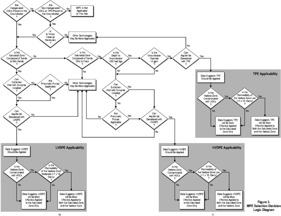
5 Generally, the high vacuum (approximately inches mercury) applications, HVDPE and TPE, are most cost effective where the target geologic formations have low permeabilities (i.e., sandy silts to clays). Both HVDPE and TPE will be effective at depths less than 50 feet BGS with low ground water production rates (<5 gpm). However, HVDPE has a broader range of application and may also be applied at greater depths and higher flow rates. The low vacuum (3 to 12 inches of mercury) application, LVDPE, is suitable for more permeable soils (i.e., sands to silty sands). LVDPE is not limited by depth of commitment or typical groundwater flow rates, however the aquifer must be able to be dewatered. Generally MPE is applied below the groundwater table. However, MPE may also be applied simultaneously above and below the water table. Where MPE is to be applied above the groundwater table, the air permeability must also be considered. Figure 3 presents a decision logic flowchart that may assist you in the selection of LVDPE, HVDPE, or TPE. Prior to implementation of the chosen MPE technology, a treatability pilot study should be performed by an experienced engineering firm. Proper interpretation of the pilot study results are needed to maximize the effectiveness of MPE. Case Studies and Costs The MPE technology has been applied at dozens of low to moderate permeability sites and has consistently proven to be more effective at removing subsurface VOCs than conventional pump-and-treat or soil vapor extraction systems alone. This is due to the increase in groundwater and contaminated soil vapor removal rates, and the volatilization of contaminants in the previously saturated soils. The increased mass removal rates result in decreased total removal costs. Note that the effectiveness of the MPE technologies are directly dependent on site characteristics (geologic, hyrogeologic, and contaminant characteristics, etc). Pilot study and/or full-scale MPE system field data, demonstrating the effectiveness of MPE at multiple military sites (including McClellan AFB, Travis AFB, Nellis AFB, FE Warren AFB, Offutt AFB, Ellsworth AFB, DDRW-Tracy Depot, and Air Force Plant-44 [AFP-44]) are currently available. Appendix A presents the results of selected case studies. Appendix A also includes estimated full-scale contaminant extraction costs, presented in dollars per pound of contaminant removed ($/lb), for each of the case studies. These costs are based on a single well extraction system operated for one year. They include capital costs, installation costs and operation and maintenance costs. The costs do not include design, well installation, or soil vapor/groundwater treatment costs. These costs also do not include any costs associated with patent requirements. As demonstrated in Appendix A, the contaminant extraction costs for MPE applications are highly site-specific. It is dependent upon the original and target clean-up level concentrations of contaminants, aquifer/vadose zone characteristics, groundwater and vapor flowrates, as well as the design and operation of the technology used. 5
 application, LVDPE, is suitable for more permeable soils (i.e., sands to silty sands).")
6 LESSONS LEARNED The key to designing an effective MPE system is experience and performing a treatability pilot study beforehand. Pilot study results provide key parameters, such as effective well vacuum, groundwater and vapor radii of influence, and groundwater and soil vapor extraction flowrates. These parameters are essential for the selection and design of vacuum pumps, submersible pumps, and eventually, groundwater and vapor treatment. Because TPE and HVDPE application parameters overlap, other site parameters will also affect your decision on which MPE technology to use. The ability to use existing extraction wells at a site may be the key factor in deciding to use HVDPE or TPE. Table 3 provides the advantages and disadvantages of HVDPE, LVDPE, TPE which may assist you in final selection of a MPE technology. Table 3. Advantages and Disadvantages Between HVDPE/LVDPE and TPE HVDPE and LVDPE TPE Advantages No limitation on depth of targeted contamination. Disadvantages Lower vacuum losses within extraction well. No limitation on groundwater production rate. Where submersible pumps are used, a standing water column above the pump is required, therefore, installation of a new extraction well with a sump may be required. More controls required for pump as compared with TPE. Groundwater stripping: up to 98% transfer of aqueous phase contaminants to vapor phase. No pumps or mechanical equipment required in well. Can be applied at existing extraction or monitoring wells. Limited to a maximum groundwater depth of approximately 50 feet below ground surface. Limited to a maximum groundwater flowrate of approximately 5 gpm. Higher vacuum losses due to lifting water from the well. 6

7 CONCLUSION For sites with VOC-contamination in the soil and/or groundwater and appropriate site characteristics, MPE is a cost effective technology. MPE has been applied at dozens of low- to moderate-permeability sites and has consistently proven to be more effective at removing subsurface VOCs than conventional pump-and-treat or soilvapor extraction systems alone. For further information or assistance on MPE applications, refer to Table 4 for points of contact or reference information. Table 4. MPE Points-of-Contact and References Points of Contact Affiliation Name Title Phone Number Site Contacts DDRW-Tracy Marshall Cloud Project Manager/ (209) Environmental Specialist Travis AFB Mark Sandy Remedial Program (707) Manager Nellis AFB Jim Pedrick Chief of (702) Environmental Restoration Division McClellan AFB Kevin Wong Remedial Program (916) Manager FE Warren AFB Barry Mountain Chief of Missile (307) Engineering Ellsworth AFB John DeYoe Remedial Program (605) Manager Offutt AFB Phil Cork Installation (402) Restoration Program Manager Wright-Patterson AFB (AFP-44) Dennis Scott Remedial Program Manager (513) x417 EPA Contacts U.S.EPA Headquarters Scott Fredericks Environmental (703) Protection Specialist U.S.EPA Headquarters Michael Hurd Chemist (703) U.S.EPA Headquarters John Blanchard P.E. (703) ACC Contacts ACC Headquarters Margaret Program Manager (757) Patterson Existing U.S.EPA Guidance "Presumptive Remedies: Site Characterization and Technology Selection for CERCLA Sites with Volatile Organic Compounds in Soils," OSWER FS. "Presumptive Response Strategy and Ex-Situ Treatment Technologies for Contaminated Groundwater at CERCLA Sites," Final, October 1996, OSWER "User s Guide to the VOCs in Soils Presumptive Remedy," April

8 Atmospheric Air Bleed Valve Vacuum Gauge Vapor-Water Separator Two-Phase Flow Water Pump To Water Phase Treatment Liquid Ring Vacuum Pump To Vapor Phase Treatment Extraction Well Vadose Zone Static Water Table Soil Vapor Flow Suction Pipe Saturated Zone Water Flow Well Screen NOTE: The extraction well may also be screened above the saturated zone for treatment of the vadose zone. Figure 1. Schematic of a TPE System

9 Groundwater Flow Vapor-Water Separator To Treatment & Disposal Electrical Control Panel Vacuum Flow Vacuum Blower To Vapor Phase Treatment Extraction Well Vadose Zone Static Water Table Well Screen Level Probe/ Controller Soil Vapor Flow Water Flow Water Extraction Pipe and Pump Wiring Saturated Zone Sump (blank well casing) Submersible Pump NOTE: The extraction well may also be screened above the saturated zone for treatment of the vadose zone. Figure 2. Schematic of a DPE System (Low Vacuum or High Vacuum)

10
11 Appendix A. Summary of Case Study Results SITE Treatment Type Depth of Water (feet BGS) Lithology Targeted Contaminant Groundwater Concentration (µg/l) Number of Extraction Wells Depth of Extraction Well (feet BGS) Effective Well Vacuum (in. of Hg) Screened Interval (feet BGS) Initial Total Mass of VOCs Removed (lbs/day) Groundwater Flow rate (GPM) Vapor Flow rate (scfm) Estimated Cost of Contaminant Extraction ($/lb) Remarks Vadose Zone Saturated Zone MPE P&T MPE P & T DDRW-Tracy OU1 TPE 24.0 silty clay silty clay TCE x x ,000 a Travis AFB, MW- 269 TPE 13.7 silts, clays silts, clays TCE 1, Travis AFB, Ragsdale & V, MW-7 TPE 10.0 silts, clays silts, clays Travis AFB, TCE, TPH, Benzene 3, OSA TPE 8.0 silty clay silty clay TCE, PCE < Nellis AFB, Site 44 TPE 45.0 silty clay caliche, silty clay TCE (VOCs) 1, b McClellan AFB, Bld.666 TPE sandy silt sandy silt TCE, PCE, Freon 8, c FE Warren AFB, 0U2, EW1 TPE 10.0 clayey, gravely, silty, sands clayey sands and clay TCE ,300 Ellsworth AFB OU-11, BG-04 TPE 18 sandy silty clay, clayey sand clayey gravel, pierre shale TCE <2 gpm (estimated) ,000 a Offutt AFB, Bld. 301 LVDPE 50.0 clay silty sand TCE 24, d McClellan AFB, Bld. 360, EW LVDPE clays, silts sandy silts, silty sand TCE (VOCs) 10, e sandy silts, silty sand TCE (VOCs) 10, e HVDPE clays, silts McClellan AFB, Bld. 360, MW- 224 LVDPE sandy silt sandy silt TCE (VOCs) 11, ,700 f HVDPE sandy silt sandy silt TCE (VOCs) 11, ,290 f Air Force Plant - 44, IRP Site 3, LVDPE Air Force Plant - 44, IRP Site 2, LVDPE Air Force Plant - 44, IRP Site 5 LVDPE sandy gravel & sandy clay sandy gravel & sandy clay sand sandy gravel & sandy clay Remarks: a. High contaminant removal costs are due to low groundwater concentrations. b. Test results indicate that LVDPE would be more effective than TPE at this site. c. Test results indicate that HVDPE would be more effective than TPE at this site. d. Test results indicate that HVDPE would be more effective than LVDPE at this site. e. HVDPE and LVDPE shown to be nearly equally cost effective for EW-321 at McClellan f. HVDPE shown to be most cost effective for MW-224 at McClellan. N/A = Not applicable Note: Costs associated with any patent requirements are not included in the cost. TCE, DCE, TCA, Freon sandy gravel & sandy clay TCE 240-2, <1 sand TCE, DCE
 Screened Interval (feet BGS) Initial Total Mass of VOCs Removed (lbs/day) Groundwater Flow rate (GPM) Vapor Flow rate (scfm) Estimated Cost of Contaminant Extraction ($/lb) Remarks Vadose Zone")
Well gauging results LNAPL in Benzol Processing Area
 Well gauging results LNAPL in Benzol Processing Area 3.59 ft 0.62 ft 4.64 ft Context Scope & Methods Onshore Results Offshore Results Summary & Conclusions 13 Page 1 of 4 Underground Storage Tanks Last
Utilizing an Innovative, Effective Site Assessment and Monitoring Tool
 Utilizing an Innovative, Effective Site Assessment and Monitoring Tool Jay W. Hodny, Ph.D. W. L. Gore & Associates, Inc., Elkton, MD, USA Laurie LaPlante, P.E. Kleinfelder, Inc., Salt Lake City, UT, USA
M Area Inactive Process Sewer Lines (MIPSL) Operable Unit CAB Recommendation #236 Update
 Operable Unit CAB Recommendation #236 Update") A Presentation to the Facilities Disposition and Site Remediation Committees SRS Citizens Advisory Board M Area Inactive Process Sewer Lines (MIPSL) Operable Unit CAB Recommendation #236 Update A Presentation
A Presentation to the Facilities Disposition and Site Remediation Committees SRS Citizens Advisory Board M Area Inactive Process Sewer Lines (MIPSL) Operable Unit CAB Recommendation #236 Update A Presentation
U. S. Army Corps of Engineers Ground Water Extraction System Subsurface Performance Checklist
 U. S. Army Corps of Engineers Ground Water Extraction System Subsurface Performance Checklist Installation Name Site Name / I.D. Evaluation Team Site Visit Date This checklist is meant to aid in evaluating
COST AND PERFORMANCE REPORT
 COST AND PERFORMANCE REPORT Pump and Treat of Contaminated Groundwater at the United Chrome Superfund Site Corvallis, Oregon September 1998 Prepared by: SITE INFORMATION Identifying Information: United
Frequently Asked Questions FAQ (click to follow link) How Does The Thermal Well System Work? How Much Does It Cost?
 How Does The Thermal Well System Work? How Much Does It Cost?") Frequently Asked Questions FAQ (click to follow link) How Does The Thermal Well System Work? How Much Does It Cost? Isn't the Power Itself Excessively Expensive? What Are The Risks Of Using ISTD? Which
Frequently Asked Questions FAQ (click to follow link) How Does The Thermal Well System Work? How Much Does It Cost? Isn't the Power Itself Excessively Expensive? What Are The Risks Of Using ISTD? Which
In-well Vapor Stripping
 Technology Overview Report TO-97-01 GWRTAC O SERIES Prepared By: Ralinda R. Miller, P.G. and Diane S. Roote, P.G. Ground-Water Remediation Technologies Analysis Center February 1997 Prepared For: Ground-Water
Bioremediation of Petroleum Hydrocarbons and Chlorinated Volatile Organic Compounds with Oxygen and Propane Gas infusion
 Bioremediation of Petroleum Hydrocarbons and Chlorinated Volatile Organic Compounds with Oxygen and Propane Gas infusion Walter S. Mulica Global Technologies Fort Collins, CO Co-Authors Mike Lesakowski
ETV JOINT VERIFICATION STATEMENT
 THE ENVIRONMENTAL TECHNOLOGY VERIFICATION PROGRAM ETV JOINT VERIFICATION STATEMENT TECHNOLOGY TYPE: APPLICATION: TECHNOLOGY NAME: Multiprobe 100 COMPANY: GROUNDWATER SAMPLING TECHNOLOGIES VOC-CONTAMINATED
Interim Summary Report for the Treatment Facility D Helipad In-Situ Bioremediation Treatability Test
 Interim Summary Report for the Treatment Facility D Helipad In-Situ Bioremediation Treatability Test June 15, 2012 Environmental Restoration Department This work was performed under the auspices of the
SOIL AND GROUNDWATER MANAGEMENT PLAN For Site Located at 420 South Avenue Rochester, New York NYSDEC Spill No. 1000563 PREPARED FOR: PREPARED BY:
 SOIL AND GROUNDWATER MANAGEMENT PLAN For Site Located at 420 South Avenue Rochester, New York NYSDEC Spill No. 1000563 PREPARED FOR: FLOWER CITY MANAGEMENT & DEVELOPMENT THE MEDICAL ARTS BUILDING (USGBC
OZONE SPARGE TECHNOLOGY FOR GROUNDWATER REMEDIATION. Charles R. Plummer, P.E., M.S., Michael D. Luckett, P.E., Shaun Porter, and Robert Moncrief
 OZONE SPARGE TECHNOLOGY FOR GROUNDWATER REMEDIATION Charles R. Plummer, P.E., M.S., Michael D. Luckett, P.E., Shaun Porter, and Robert Moncrief ABSTRACT Ozone sparging is an oxidization remedial technology
Bioremediation of contaminated soil. Dr. Piyapawn Somsamak Department of Environmental Science Kasetsart University
 Bioremediation of contaminated soil Dr. Piyapawn Somsamak Department of Environmental Science Kasetsart University Outline Process description In situ vs ex situ bioremediation Intrinsic biodegradation
Long-Term Monitoring Network Optimization Evaluation. for. Wash King Laundry Superfund Site Lake County, Michigan
 Long-Term Monitoring Network Optimization Evaluation for Wash King Laundry Superfund Site Lake County, Michigan June 2006 Solid Waste and Emergency Response (5102P) EPA 542-R-06-004 December 2006 www.epa.gov
Former Williams AFB Restoration Advisory Board (RAB)
") Headquarters U.S. Air Force I n t e g r i t y - S e r v i c e - E x c e l l e n c e Former Williams AFB Restoration Advisory Board (RAB) February 24, 2009 Highland High School 4301 E. Guadalupe Rd. Gilbert,
Headquarters U.S. Air Force I n t e g r i t y - S e r v i c e - E x c e l l e n c e Former Williams AFB Restoration Advisory Board (RAB) February 24, 2009 Highland High School 4301 E. Guadalupe Rd. Gilbert,
Prepared for ENRY2000, Belgrade, Yugoslavia, September 27, 2001
 Prepared for ENRY2000, Belgrade, Yugoslavia, September 27, 2001 PERSPECTIVES ON INNOVATIVE CHARACTERIZATION AND REMEDIATION TECHNOLOGIES FOR CONTAMINATED SITES W.W. Kovalick, Jr. Technology Innovation
Tim Johnson, Mike Truex, Jason Greenwood, Chris Strickland, Dawn Wellman: Pacific Northwest National Laboratory
 3D Site Characterization and Autonomous Remedial Process Monitoring Using High Performance Electrical Resistivity and Induced Polarization Tomographic Imaging Tim Johnson, Mike Truex, Jason Greenwood,
Key Factors for Successful DPVE Remediation at Hydrocarbon-Impacted Sites. by Wanda Sakura, John Agar & Tai Wong
 Key Factors for Successful DPVE Remediation at Hydrocarbon-Impacted Sites by Wanda Sakura, John Agar & Tai Wong OUTLINE What is DPVE? Why DPVE? How to design it? How should it be operated? How well would
New Cumberland Army Depot Formerly Used Defense Site (FUDS) Marsh Run Park Site Restoration Community Meeting
 Marsh Run Park Site Restoration Community Meeting") New Cumberland Army Depot Formerly Used Defense Site (FUDS) Marsh Run Park Site Restoration Community Meeting Fairview Township, York County, Pennsylvania April 23, 2013 N US Army Corps of Engineers Depot
New Cumberland Army Depot Formerly Used Defense Site (FUDS) Marsh Run Park Site Restoration Community Meeting Fairview Township, York County, Pennsylvania April 23, 2013 N US Army Corps of Engineers Depot
Vulnerability Assessment
 Vulnerability Assessment VULNERABILITY As used in this report, vulnerability refers to the sensitivity of groundwater to contamination, and is determined by intrinsic characteristics of the aquifer. It
Innovative LNAPL Recovery Techniques
 Innovative LNAPL Recovery Techniques RTDF NON-AQUEOUS PHASE LIQUID (NAPL) CLEANUP ALLIANCE San Antonio, Texas February 7-8, 2006 Presented by: Patrick E. Haas P. E. Haas & Associates, LLC http://www.phaas.net
SUCCESSFUL FIELD-SCALE IN SITU THERMAL NAPL REMEDIATION AT THE YOUNG-RAINEY STAR CENTER
 Paper 2B-01, in: A.R. Gavaskar and A.S.C. Chen (Eds.), Remediation of Chlorinated and Recalcitrant Compounds 2004. Proceedings of the Fourth International Conference on Remediation of Chlorinated and Recalcitrant
In Situ Bioremediation of Chlorinated Solvent R&D 100 Award Winner
 In Situ Bioremediation of Chlorinated Solvent R&D 100 Award Winner Description This patented bioremediation technology combines natural gas injection and air stripping to stimulate microbes to completely
REMEDIATION TECHNIQUES FOR SOIL AND GROUNDWATER
 REMEDIATION TECHNIQUES FOR SOIL AND GROUNDWATER X.H. Zhang Department of Environmental Science & Engineering, Tsinghua University, Beijing, China Keywords: Remediation, soil, groundwater, aquifer, contamination,
INTEGRATED METHODS IN COST EFFECTIVE AQUIFER REMEDIATION: 3 FIELD EXPERIENCES
 INTEGRATED METHODS IN COST EFFECTIVE AQUIFER REMEDIATION: 3 FIELD EXPERIENCES PRANDI Alberto XELLA Claudio: Water & Soil Remediation S.r.l., Levata di Curtatone (MN), Italy. SUMMARY Groundwater impacted
Soil remediation you can trust In Situ Thermal Desorption. The real ISTD TERRATHERM R TECHNOLOGY. Technology
 Soil remediation you can trust In Situ Thermal Desorption TERRATHERM R TECHNOLOGY Technology The real ISTD ISTD Testing the efficiency Our pilot ISTD system is easy and ready to use if a client wants to
Distribution Restriction Statement
 CEMP-R Engineer Manual 1110-1-4010 Department of the Army U.S. Army Corps of Engineers Washington, DC 20314-1000 EM 1110-1-4010 1 June 1999 Engineering and Design MULTI-PHASE EXTRACTION Distribution Restriction
Site Assessment for the Proposed Coke Point Dredged Material Containment Facility at Sparrows Point
 Site Assessment for the Proposed Coke Point Dredged Material Containment Facility at Sparrows Point Prepared for Maryland Port Administration 2310 Broening Highway Baltimore, MD 21224 (410) 631-1022 Maryland
State of Rhode Island Department of Environmental Management Division of Site Remediation. Policy Memo 95-01
 State of Rhode Island Department of Environmental Management Division of Site Remediation Policy Memo 95-01 Guidelines for the Management of Investigation Derived Wastes 1.0 Purpose The purpose of this
FIVE-YEAR REVIEW REPORT MASON COUNTY LANDFILL SUPERFUND SITE LUDINGTON, MICHIGAN FEBRUARY, 2001
 FIVE-YEAR REVIEW REPORT MASON COUNTY LANDFILL SUPERFUND SITE LUDINGTON, MICHIGAN FEBRUARY, 2001 I. INTRODUCTION Section 121(c) of the Comprehensive Environmental Response, Compensation and Liability Act
Community Involvement Plan
 East Central Phoenix Water Quality Assurance Revolving Fund (WQARF) Sites Phoenix, Arizona Community Involvement Plan Corner of 40 th Street and Osborn March 2013 ADEQ Document No. EQR 13-01 Introduction
COST AND PERFORMANCE LNAPL C
 REPORT FOR COST AND PERFORMANCE LNAPL C HARACTERIZATION AND REMEDIATION Multi-Phase Extraction and Dual-Pump Recovery of LNAPL at the BP Former Amoco Refinery, Sugar Creek, MO March 2005 Office of Solid
Pierre VOC Ground Water Investigation and MTBE Remediation Pilot Study
 Pierre VOC Ground Water Investigation and MTBE Remediation Pilot Study Joint Meeting of 2007 Eastern South Dakota Water Conference and the 52 nd Annual Midwest Ground Water Conference October 30, 2007
Street Address (number and street): City: County: ZIP Code: B. CURRENT SITE PRIORITY INFORMATION Was free product present this quarter?
: City: County: ZIP Code: B. CURRENT SITE PRIORITY INFORMATION Was free product present this quarter?") QUARTERLY MONITORING REPORT (QMR) COVER SHEET AND REPORT FORMAT State Form 56087 (6-16) 329 IAC 9-5 Indiana Department of Environmental Management Office of Land Quality Leaking Underground Storage Tank
QUARTERLY MONITORING REPORT (QMR) COVER SHEET AND REPORT FORMAT State Form 56087 (6-16) 329 IAC 9-5 Indiana Department of Environmental Management Office of Land Quality Leaking Underground Storage Tank
Soil and Groundwater. Removing Contaminants. Groundwater. Implementing. Remediation. Technologies 1 / 6
 carol townsend, C: 469-263-4343, carol.townsend@sageenvironmental.com robert sherrill, C: 512-470-8710, robert.sherrill@sageenvironmental.com October 2012. ALL RIGHTS RESERVED. Revised Nov. 12, 2012 Background:
11 September 2002, 0930 Hours
 Final Meeting Minutes Travis Air Force Base Environmental Management Building 246, Upstairs Conference Room Installation Restoration Program Remedial Program Managers Meeting 11 September 2002, 0930 Hours
SEAR Wastewater Treatment: Contaminant Removal and Material Recovery
 ESTCP SEAR Wastewater Treatment: Contaminant Removal and Material Recovery U.S. Environmental Protection Agency National Risk Management Research Laboratory Cincinnati, Ohio SEAR Workshop Outline Motivation
Ground-Water Circulation Wells
 United States Solid Waste and EPA 542-R-98-009 Environmental Protection Emergency Response October 1998 Agency (5102G) http://www.epa.gov/swertio1 http://clu-in.org Field Applications of In Situ Remediation
FARM A SYST Farmstead Assessment System. Drinking Water Well Condition
 G3536 1W FARM A SYST Farmstead Assessment System Worksheet #1 Assessing the Risk of Groundwater Contamination from Why should I be concerned? Drinking Water Well Condition About 95 percent of this country
STATE OF TENNESSEE DEPARTMENT OF ENVIRONMENT AND CONSERVATION DIVISION OF UNDERGROUND STORAGE TANKS TECHNICAL GUIDANCE DOCUMENT - 008
 STATE OF TENNESSEE DEPARTMENT OF ENVIRONMENT AND CONSERVATION DIVISION OF UNDERGROUND STORAGE TANKS TECHNICAL GUIDANCE DOCUMENT - 008 Effective Date - January 13, 1992 Revised Date - November 19, 1993
VAPOR INTRUSION SCREENING LEVEL (VISL) CALCULATOR USER S GUIDE
 CALCULATOR USER S GUIDE") VAPOR INTRUSION SCREENING LEVEL (VISL) CALCULATOR USER S GUIDE U.S. ENVIRONMENTAL PROTECTION AGENCY OFFICE OF SOLID WASTE AND EMERGENCY RESPONSE OFFICE OF SUPERFUND REMEDIATION AND TECHNOLOGY INNOVATION
VAPOR INTRUSION SCREENING LEVEL (VISL) CALCULATOR USER S GUIDE U.S. ENVIRONMENTAL PROTECTION AGENCY OFFICE OF SOLID WASTE AND EMERGENCY RESPONSE OFFICE OF SUPERFUND REMEDIATION AND TECHNOLOGY INNOVATION
CHAPTER 7: REMEDIATION TECHNOLOGIES FOR CONTAMINATED GROUNDWATER
 CHAPTER 7: REMEDIATION TECHNOLOGIES FOR CONTAMINATED GROUNDWATER There are a number of technologies that are being use to remediate contaminated groundwater. The choice of a certain remediation technology
Evaluation of Site-Specific Criteria for Determining Potability
 Evaluation of Site-Specific Criteria for Determining Potability and Cleanup Goals for Impacted Groundwater This paper presents considerations used to evaluate site-specific criteria for determining groundwater
TCE. The Use & Remediation of TCE at NASA. Keep reading. is developing innovative. NASA s pollution prevention efforts significantly reduced TCE use
 National Aeronautics and Space Administration Space flight and exploration begin with developing innovative technologies here on Earth. Our commitment to environmental stewardship is central to that effort.
DRAFT. GROUNDWATER REMEDY COMPLETION STRATEGY: Moving Forward with Completion in Mind
 GROUNDWATER REMEDY COMPLETION STRATEGY: Moving Forward with Completion in Mind Table of Contents 1. Introduction...2 1.1 Purpose and Scope...2 1.2 Background...3 2. Elements of a Groundwater Remedy Completion
Secondary Containment Systems for Aboveground Storage Tanks
 New York tate Department of Environmental Conservation Division of pills Management 50WolfRoad Albany,NewYork12233-3750 Telephone: (518) 457-4351 FAX: (518)457-4332 MEMORANDUM eptember 28, 1994 To: Regional
Why In Situ Thermal Desorption Can Be the Most Cost-Effective Remediation Method for Many Sites
 Why In Situ Thermal Desorption Can Be the Most Cost-Effective Remediation Method for Many Sites Ralph S. Baker (rbaker@terratherm.com), John M. Bierschenk, John LaChance, James P. Galligan and Devon Tarmasiewicz
GAS WELL/WATER WELL SUBSURFACE CONTAMINATION
 GAS WELL/WATER WELL SUBSURFACE CONTAMINATION Rick Railsback Professional Geoscientist CURA Environmental & Emergency Services rick@curaes.com And ye shall know the truth and the truth shall make you free.
Technical Impracticability Decisions for Ground Water at CERCLA Response Action and RCRA Corrective Action Sites
 U.S. Department of Energy Office of Environmental Policy and Assistance RCRA/CERCLA Information Brief DOE/EH-413/9814 (August 1998) Technical Impracticability Decisions for Ground Water at CERCLA Response
1.34 WASTE CONTAINMENT AND SITE REMEDIATION TECHNOLOGY TAKE-HOME FINAL EXAM DUE FRIDAY MAY 7, 2004 AT 9:30 AM
 1.34 WASTE CONTAINMENT AND SITE REMEDIATION TECHNOLOGY TAKE-HOME FINAL EXAM DUE FRIDAY MAY 7, 2004 AT 9:30 AM This is an open-book exam, but the work should be yours alone. Please do not work with others
Cleaning up the environment is an important focus
 BLS U.S. BUREAU OF LABOR STATISTICS Careers in Environmental Remediation James Hamilton Report 8 Cleaning up the environment is an important focus of the green economy. Sites that are polluted because
V. ENVIRONMENTAL IMPACT ANALYSIS E. Hazardous Materials
 E. HAZARDOUS MATERIALS An Environmental Site Assessment Phase I Update was performed on the subject properties by California Environmental Inc. in March 2000 1. This report is included in Appendix E of
Straight Talk On Tanks Leak Detection Methods For Petroleum Underground Storage Tanks And Piping
 Straight Talk On Tanks Leak Detection Methods For Petroleum Underground Storage Tanks And Piping Printed on Recycled Paper Contents Do You Have Questions About Leak Detection?...1 An Overview Of Leak Detection
Presented by: Craig Puerta, PE, MBA December 12, 2012
 Presented by: Craig Puerta, PE, MBA December 12, 2012 Established in 2010 under charter from New York State to transfer lower priority sites from State s program. First municipally-run brownfield cleanup
Axial and Mixed Flow Pumps for Large Volume Pumping
 Vertical Industrial and Process Axial and Mixed Flow for Large Volume Pumping Encased (Can ) Water and Process Liquid Vertical Turbine for Water Supply from Drilled Wells Vertical close coupled single
3-D Data Visualization Taking the Next Step in Data Presentation
 3-D Data Visualization Taking the Next Step in Data Presentation Stephen Dyment USEPA Office of Superfund Remediation and Technology Innovation dyment.stephen@epa.gov 15 th Annual OSC Readiness Training
Bioremediation. Biodegradation
 Bioremediation A technology that encourages growth and reproduction of indigenous microorganisms (bacteria and fungi) to enhance biodegradation of organic constituents in the saturated zone Can effectively
PCB SPIU CLEANUP CAUSE AND EFFECT DIAGRAM. Bruce A. Bohnen Technical Director Integrated Chemistries, Incorporated 1970 Oakcrest Avenue, Suite 215
 CHEMICAL SPILL CLEANUP TECHNOLOGY Bruce A. Bohnen Technical Director Integrated Chemistries, Incorporated 1970 Oakcrest Avenue, Suite 215 St. Paul, MN 55113 Building structures occasionally are contaminated
CHAPTER 16 REMEDIAL TECHNOLOGIES
 Hazardous Waste Management, nd ed. Instructors Manual CHAPTER 16 REMEDIAL TECHNOLOGIES Supplemental Questions: The opening quote describes the fifth labor of Hercules. How many labors were there and what
TECHNICAL REPORT TR-2306-ENV
 ENGINEERING SERVICE CENTER Port Hueneme, California 93043-4370 TECHNICAL REPORT TR-2306-ENV COST AND PERFORMANCE REPORT FOR A PERSULFATE TREATABILITY STUDY AT NAVAL AIR STATION NORTH ISLAND Prepared by
Guidance for Design, Installation and Operation of In Situ Air Sparging Systems
 Guidance for Design, Installation and Operation of In Situ Air Sparging Systems RR-186 February 2015 Purpose This is a guide to using in situ air sparging as a remediation technology. In situ air sparging
4 th & Carey Groundwater. Remediation Project and Reverse Osmosis Water Treatment System
 4 th & Carey Groundwater Remediation Project and Reverse Osmosis Water Treatment System Contaminated City Well Well #8 4 th and Carey Groundwater contamination from industry was discovered in the Southeast
A MODEL OF IN SITU BIOREMEDIATION THAT INCLUDES THE EFFECT OF RATE- LIMITED SORPTION AND BIOAVAILABILITY
 A MODEL OF IN SITU BIOREMEDIATION THAT INCLUDES THE EFFECT OF RATE- LIMITED SORPTION AND BIOAVAILABILITY J. Huang and M.N. Goltz Department of Engineering and Environmental Management, Air Force Institute
Mark A. Lehar, P.Geo. Regional Environmental Lead and Senior Environmental Geologist
 Mark A. Lehar, P.Geo. Regional Environmental Lead and Senior Environmental Geologist Exova Seminar: 15 January 2016 HYDRASleeve TM Focused Sampling - Monitoring Well Sampling Using No Purge HYDRASleeves
BIOREMEDIATION: A General Outline www.idem.in.gov Mitchell E. Daniels, Jr.
 TECHNICAL GUIDANCE DOCUMENT INDIANA DEPARTMENT OF ENVIRONMENTAL MANAGEMENT BIOREMEDIATION: A General Outline www.idem.in.gov Mitchell E. Daniels, Jr. Thomas W. Easterly Governor Commissioner 100 N. Senate
CHAPTER 13 LAND DISPOSAL
 CHAPTER 13 LAND DISPOSAL Supplemental Questions: Which of Shakespeare's plays is the source of the opening quote? The Tempest [1611-1612],Act: I, Scene: i, Line: 70. 13-1. Cite four reasons landfills remain
Cost-Effective Bioremediation of Perchlorate in Soil & Groundwater
 Cost-Effective Bioremediation of Perchlorate in Soil & Groundwater Evan Cox - GeoSyntec Consultants Elizabeth Edwards - University of Toronto Scott Neville & Michael Girard - Aerojet Outline Perchlorate
INFO TECH: ENVIRONMENTAL CONCERNS
 INFO TECH: ENVIRONMENTAL CONCERNS A Summary of Environmental Concerns Regarding Contamination at Information Technology High School (Q502) 21-16 44 Road, Long Island City Queens, New York 11101 Lenny Siegel
Inventory of Performance Monitoring Tools for Subsurface Monitoring of Radionuclide Contamination
 Inventory of Performance Monitoring Tools for Subsurface Monitoring of Radionuclide Contamination H. Keith Moo-Young, Professor, Villanova University Ronald Wilhelm, Senior Scientist, U.S. EPA, Office
In-Situ Remediation Strategies as Sustainable Alternatives to Traditional Options. Ryan Bernesky, B.Sc., P.Ag. February 26, 2013
 In-Situ Remediation Strategies as Sustainable Alternatives to Traditional Options Ryan Bernesky, B.Sc., P.Ag. February 26, 2013 Outline Introduction to Contaminated Sites and Remediation Strategies In-Situ
BIOGENIE S CONTAMINATED SOIL TREATMENT FACILITIES. NATO CCMS Pilot Study Athens, GR. Guaranteed Site Remediation Solutions
 BIOGENIE S CONTAMINATED SOIL TREATMENT FACILITIES NATO CCMS Pilot Study Athens, GR. Guaranteed Site Remediation Solutions International Presence United Kingdom France Canada United States Oil Refinery
STATE OF VERMONT AGENCY OF NATURAL RESOURCES DEPARTMENT OF ENVIRONMENTAL CONSERVATION WASTE MANAGEMENT DIVISION SOLID WASTE MANAGEMENT PROGRAM
 STATE OF VERMONT AGENCY OF NATURAL RESOURCES DEPARTMENT OF ENVIRONMENTAL CONSERVATION WASTE MANAGEMENT DIVISION SOLID WASTE MANAGEMENT PROGRAM Solid Waste Management Program Waste Management Division 103
Letter Health Consultation
 Letter Health Consultation FORMER FASHION CARE CLEANERS 2213 WEST MERCURY BOULEVARD HAMPTON, VIRGINIA Prepared by Virginia Department of Health AUGUST 21, 2012 Prepared under a Cooperative Agreement with
PILOT PROJECT TO OPTIMIZE GROUND WATER REMEDIATION SYSTEMS AT RCRA CORRECTIVE ACTION FACILITIES: SUMMARY REPORT AND LESSONS LEARNED
 PILOT PROJECT TO OPTIMIZE GROUND WATER REMEDIATION SYSTEMS AT RCRA CORRECTIVE ACTION FACILITIES: SUMMARY REPORT AND LESSONS LEARNED REPORT SUBMITTED: DECEMBER 22, 2005 This page is intentionally left blank.
Accelerated Site Cleanup Using a Sulfate-Enhanced In Situ Remediation Strategy
 Accelerated Site Cleanup Using a Sulfate-Enhanced In Situ Remediation Strategy By: Sheri Knox, Tim Parker, & Mei Yeh YOUR NATURAL SOLUTIONS Patented Methods for In Situ Bioremediation Slide 2 About EOS
FINAL PLAN OF REMEDIAL ACTION
 FINAL PLAN OF REMEDIAL ACTION 1000 FRENCH STREET SITE Wilmington, Delaware DE 1115 June 1999 Department of Natural Resources and Environmental Control Division of Air and Waste Management Site Investigation
A Decision Framework for Selecting Remediation Technologies at Hydrocarbon-Contaminated Sites
 Journal of Soil Contamination, 2(2): (1993) A Decision Framework for Selecting Remediation Technologies at Hydrocarbon-Contaminated Sites Neil M. Ram, David H. Bass, Robert Falotico, and Maureen Leahy
In-situ Bioremediation of oily sediments and soil
 1 Peter Werner, Jens Fahl, Catalin Stefan DRESDEN UNIVERSITY OF TECHNOLOGY In-situ Bioremediation of oily sediments and soil 2 WHAT IS OIL? MIXTURE of aliphatic and aromatic hydrocarbons Different composition
Vapor Phase Transport as a Groundwater Contamination Process at Arid Landfill Sites
 Vapor Phase Transport as a Groundwater Contamination Process at Arid Landfill Sites G.R. Walter 1, A.M. Geddis 1, R. Murray and.w. Bentley 1 1 ydro Geo Chem, Inc. 51 W. Wetmore, Tucson, Arizona, 8575 Office
Risk-Based Decision Making for Site Cleanup
 July 2013 Risk-Based Decision Making for Site Cleanup The Oklahoma Department of Environmental Quality (DEQ) has adopted a risk based decision making process to provide a framework for determining cleanup
In-situ Chemical Oxidation via Ozone at a Multiple-Remedy UST Site - 9124
 ABSTRACT In-situ Chemical Oxidation via Ozone at a Multiple-Remedy UST Site - 9124 Frederic R. Coll and R.A. Moore URS Corporation Foster Plaza 4, Suite 300 501 Holiday Drive Pittsburgh, PA 15220 URS Corporation
Bioremediation. Introduction
 Bioremediation Introduction In the twentieth century, the ever increase in the global human population and industrialization led to the exploitation of natural resources. The increased usage of heavy metals
SOIL GAS MODELLING SENSITIVITY ANALYSIS USING DIMENSIONLESS PARAMETERS FOR J&E EQUATION
 1 SOIL GAS MODELLING SENSITIVITY ANALYSIS USING DIMENSIONLESS PARAMETERS FOR J&E EQUATION Introduction Chris Bailey, Tonkin & Taylor Ltd, PO Box 5271, Wellesley Street, Auckland 1036 Phone (64-9)355-6005
Construction sites are dewatered for the following purposes:
 9. DEWATERING CONTROL OF GROUNDWATER Construction of buildings, powerhouses, dams, locks and many other structures requires excavation below the water table into water-bearing soils. Such excavations require
Remediation of VOC Contaminated Groundwater
 Remediation of VOC Contaminated Groundwater Background Contaminated groundwater has become an ever-increasing problem in the United States and around the world. Treatment and disposal of waste is a serious
Nutrient Reduction by Use of Industrial Deep Injection Wells, Miami-Dade County, Florida
 GWPC September 27, 2015 Nutrient Reduction by Use of Industrial Deep Injection Wells, Miami-Dade County, Florida Virginia Walsh, PhD, P.G. Miami-Dade Water and Sewer Department Ed Rectenwald, P.G. MWH
Characterizing Beauty Salon Wastewater for the Purpose of Regulating Onsite Disposal Systems
 Characterizing Beauty Salon Wastewater for the Purpose of Regulating Onsite Disposal Systems Fred Bowers 1,2, Ph.D. New Jersey Department of Environmental Protection Division of Water Quality August 14,
DEPARTMENT OF ENVIRONMENTAL PROTECTION BUREAU OF WATER SUPPLY MANAGEMENT. Principles for Ground Water Pollution Prevention and Remediation
 DEPARTMENT OF ENVIRONMENTAL PROTECTION BUREAU OF WATER SUPPLY MANAGEMENT DOCUMENT NUMBER: 383-0800-001 EFFECTIVE DATE: December 1, 1996 TITLE: AUTHORITY: POLICY: Principles for Ground Water Pollution Prevention
Barometric Effects on Transducer Data and Groundwater Levels in Monitoring Wells D.A. Wardwell, October 2007
 Barometric Effects on Transducer Data and Groundwater Levels in Monitoring Wells D.A. Wardwell, October 2007 Barometric Effects on Transducer Data Barometric Fluctuations can Severely Alter Water Level
CONSTANT HEAD AND FALLING HEAD PERMEABILITY TEST
 CONSTANT HEAD AND FALLING HEAD PERMEABILITY TEST 1 Permeability is a measure of the ease in which water can flow through a soil volume. It is one of the most important geotechnical parameters. However,
ENCE 4610 Foundation Analysis and Design
 This image cannot currently be displayed. ENCE 4610 Foundation Analysis and Design Shallow Foundations Total and Differential Settlement Schmertmann s Method This image cannot currently be displayed. Strength
Chapter 12 Physical and Chemical Groundwater Remediation Technologies
 Chapter 12 Physical and Chemical Groundwater Remediation Technologies Krishna R. Reddy Abstract Groundwater is the main source of drinking water as well as agricultural and industrial usage. Unfortunately,
Incorporating Greener Cleanups into Remedy Reviews
 Association of State and Territorial Solid Waste Management Officials (ASTSWMO) Incorporating Greener Cleanups into Remedy Reviews Prepared by the Greener Cleanups Task Force Under the Sustainability Subcommittee
Frequently Asked Questions on the Alberta Tier 1 and Tier 2 Soil and Groundwater Remediation Guidelines. February 2008
 Frequently Asked Questions on the Alberta Tier 1 and Tier 2 Soil and Groundwater Remediation Guidelines February 2008 Frequently Asked Questions on the Alberta Tier 1 and Tier 2 Soil and Groundwater Remediation
STATEMENT OF BASIS HYPERGOL SUPPORT BUILDING SWMU 65 NATIONAL AERONAUTICS AND SPACE ADMINISTRATION KENNEDY SPACE CENTER BREVARD COUNTY, FLORIDA
 STATEMENT OF BASIS HYPERGOL SUPPORT BUILDING SWMU 65 NATIONAL AERONAUTICS AND SPACE ADMINISTRATION KENNEDY SPACE CENTER BREVARD COUNTY, FLORIDA PURPOSE OF STATEMENT OF BASIS This Statement of Basis (SB)
Description Purpose Health Education. Health Assessment. Outcomes of the program Partners Contact Information
 1 Description Purpose Health Education Message Mapping Developing Community Interaction Health Assessment Identifying Contaminants of Concern Elements of Exposure Pathways Outcomes of the program Partners
Redeveloping Former Gas Stations
 Redeveloping Former Gas Stations Michael C. Murphy Phillips Lytle LLP Buffalo, NY Kenneth R. Crystal Phillips Lytle LLP New York, NY F ormer gas station sites are often prime targets for redevelopment.
WM2013 Conference, February 24 28, 2013, Phoenix, Arizona, USA
 Hanford Site 100-N Area In Situ Bioremediation of UPR-100-N-17, Deep Petroleum Unplanned Release - 13245 Daniel G. Saueressig Washington Closure Hanford, 2620 Fermi, Richland, Washington, 99354, dgsauere@wch-rcc.com
Use of Alternate Concentration Limits (ACLs) to Determine Cleanup or Regulatory Levels Under RCRA and CERCLA
 to Determine Cleanup or Regulatory Levels Under RCRA and CERCLA") U.S. Department of Energy Office of Environmental Policy and Assistance ACL Information Brief DOE/EH-413-9912 (December 1999) DEPARTMENT OF ENERGY UN ITED STATES OF AMERICA Use of Alternate Concentration
U.S. Department of Energy Office of Environmental Policy and Assistance ACL Information Brief DOE/EH-413-9912 (December 1999) DEPARTMENT OF ENERGY UN ITED STATES OF AMERICA Use of Alternate Concentration
Training Guide. An Introduction to Well Drawdown
 Training Guide An Introduction to Well Drawdown Rural and Small Systems Training Guide An Introduction to Well Drawdown Michael J. Lytle, Arizona Water Association Contributing Author Paul Markowski, Nebraska