Operating Instruction Manual. Read All Instructions Before Operating. Tru-Hitch* Model 250 & 250P
|
|
|
- Allen Potter
- 9 years ago
- Views:
Transcription
1 16 W. West Hill Road Barkhamsted Ct PH PH FAX Manufacturers of Patented Truck Trailering Lifts Operating Instruction Manual Read All Instructions Before Operating Tru-Hitch* Model 250 & 250P Specification Standard Severe Service Option Gross Lift Capacity 25,000 lbs. 30,000 lbs. Trailering Capacity 80,000 lbs. G.C.W 120,000 lbs. G.C.W. Hitch Weight with Attachments 6,700 lbs. 7,200 lbs. Hydraulic Operating Pressure 3,000 psi 3,000 psi Tru-Hitch* is the safest device for transporting a truck. The versatility or the Tru-Hitch* s fifth wheel hitch allows any truck to be transported as a semi-trailer, allowing optimal weight distribution between tractor and trailer. *Tru-Hitch is a registered trademark Page 1


2 Tru-Hitch* Components Figure A Control valve levers (#1) Figure B Electric Control Box Figure C Page 2

3 Principle of Operation 1. Refer to Figure A for the part names for the Tru-Hitch* 2. The majority of these procedures are performed with only the first two control valve levers, the MAST and the BOOM levers. Keep this in mind as you learn to use the hitch. 3. The control valve levers activate hydraulic pistons to extend or retract. For instance, if the boom lever is pressed down, the pistons extend and the angle between the boom and the Mast (the boom angle) is increased. If the boom valve lever is pushed up, the pistons retract and the boom angle is decreased. When the weight of the truck is resting on the booms, the effect of increasing (extend) boom angle is to raise the end of the truck that is resting on the boom. If the boom angle is decreased (retract), the effect is to lower the end of the truck that is resting on the boom. These raising and lowering effects occur because of the pivoting motion of the Tru-Hitch*. Operators should become familiar with the extension and retraction action of the hydraulic pistons before using the Tru-Hitch* to transport a truck. 4. The flow control valves are used to keep some back pressure in the hydraulic system. There is a flow control valve for the mast and one for the boom hydraulics. They are adjusted by turning the knob as needed. With no load on the hitch you want to have approximately psi of back pressure showing on the hitch pressure gauge. You can adjust the mast pressure when retracting the mast in the track and you can adjust the boom when you are extending the boom down into the tow position. Once set, you should not have to re-adjust unless outside temperatures (cold/hot), when using the hitch, change the flow of the hydraulic oil. Flow valve Operating Procedures Notes: A. if not using wetlines of tractor, the electric control box must be set to electric and the motor control switch must be depressed to use valve control levers. B. The remote control can be used where instructed to use valve control levers. 1. Initial coupling to tractor to the Tru-Hitch* The operating procedures assume that initially the Tru-Hitch* is set on the ground with the boom extended at a right angle to the Mast section as shown in figure A. To ready the Tru-Hitch* for coupling to the tractor, turn the key to the on position and use the control lever to engage the hydraulic system. (Tractor should be positioned close enough to attach wetlines and engage PTO.) Extend or Retract the mast pistons as necessary to position the king pin on the fifth wheel section (5) level with the tractors fifth wheel. Back the tractor under the horizontal frame until the king pin engages the fifth wheel and is latched. Carefully re-check the latch to make sure the king pin is fully engaged. Note: make sure that the transport legs (7) are in stored position prior to backing under the Tru-Hitch* to prevent damage to the legs. Page 3
 lifts sufficiently to allow the rear support legs (7) to be lowered down over the tractor s after-frame.")
 B. Use the control levers to retract the boom.")
 and insert both pins.")
 F.")
4 2. Procedure to transport the Tru-Hitch without a load A. Use the control lever to extend the boom angle until the fifth wheel section(5) lifts sufficiently to allow the rear support legs (7) to be lowered down over the tractor s after-frame. To lower the supports, rotate the handle (8) clockwise and lock them into place. Once locked use the control lever to retract the boom and rest the Tru-Hitch on the transport legs. (you may also need to extend the mast slightly to support the Tru-Hitch* on the legs) B. Use the control levers to retract the boom. (Boom Extensions should be fully retracted when performing this step.) Retract until the boom (3) is vertical and resting against the Mast Section (4). Watch overhead for obstacles when performing this function. C. Use the control levers to extend the mast until the pivot arrow on the mast lines up with the Pivot Hole (14) and insert both pins. (Safety clevises (16) should be removed for this step) D. Once pinned, retract the mast to fold the Tru-Hitch onto the tractor. Retract until the pivot pins loosen and can be removed. E. Extend the mast until the supports reach the stops at the front of the fifth wheel section. (Do not over extend the mast as the supports can be bent if you extend too far) F. Install the safety clevises in the holes at the end of the mast track and cross chain Safety Clevis Transport Cross Chain to the rear of the tractor taking up as much slack as possible. Then using valve control levers retract the mast slightly to tension the chains. G. The Tru-Hitch is now ready for transport. 3. Procedure to fold the Tru-Hitch down for towing from the transport position A. Using the valve control levers Extend the mast slightly to loosen the safety chains. Remove the chains and safety clevises. B. Using the valve control levers, Retract the mast until the pivot arrow on the mast lines up with the pivot hole (14) and insert the pins. C. Using the valve control levers, Extend the mast until it is vertical, in the track on the fifth wheel section, and the pivot pin loosens. Remove the pins. Page 4

 G.")
5 Procedure to fold the Tru-Hitch down for towing from the transport position- continued D. Using the valve control levers, Retract the mast until it fully engages the track on the fifth wheel section. Install the safety clevises. E. Using the valve control levers, Extend the boom until it is horizontal to the ground. F. If necessary, Retract the mast to bring the boom section about an inch off the ground. (If you are always using the same tractor for towing, you will set the mast in the correct position during step D so that booms will end up an inch off the ground each time you perform step E.) G. The Tru-Hitch* is now ready to back under the vehicle to be towed. 4. Procedure to load a truck on the Tru-Hitch* A. Position the tractor with the Tru-Hitch* folded down so that it can be backed straight under the truck to be transported, or so that the truck can be winched straight over the booms. B. Place the receivers (11) in the hole setting that allows the wheel stops to contact the wheels on the towed vehicle while keeping clearance between the front of the towed vehicle and the bumper stops on the Tru-Hitch*. Be sure to fully engage all of the pins that hold the receivers on the boom. C. Carefully back the Tru-Hitch* under the truck until the wheel stops contact the tires of the truck, making sure there is clearance between the boom and the truck. Make sure there are no obstructions before backing the boom under the truck s carriage. If necessary the winch (17) on the Tru-Hitch can be used to pull a truck over the booms when backing under the truck to be towed is not practical. Winching setup D. Using the valve control levers Extend the boom extensions (9) to the points where rear hook-up chains will be fastened to the truck. E. Using the valve control levers, Extend the boom allowing the transport legs to clear the after frame of the tractor and to be raised by turning the handle counter-clockwise. The boom may raise the truck slightly when positioning to raise the transport legs. Make sure the truck is secure from moving and that the boom only contacts the axle(s) if this happens. Note: Never tow with the transport legs in the down position. F. Using the valve control levers, Retract the boom to bring the boom extensions as close to the rear hook-up point as possible without interfering with any of the components of the trucks undercarriage. Page 5


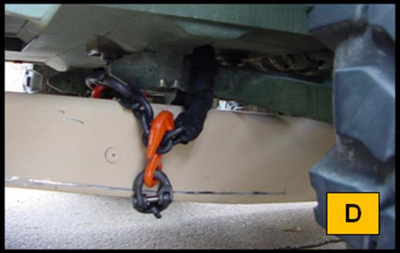
6 Procedure to load a truck on the Tru-Hitch*- continued G. Attach the rear hook-up chains to the boom extensions by using the ½ hook-up chains, the frame hooks, or combination as needed. See the photos of acceptable hookups in safety section. Note: Never wrap a chain around an individual frame flange or cross member flange. H. Using the valve control levers, Extend the boom to tension the hook-up chains, and then lift the truck by contacting the axle resting on the boom. Be sure that the booms do not interfere with any other components under the truck. Extend the boom until the truck is lifted off the ground and the fifth wheel section is as level as possible. Place the boom lock pin in the hole that is visible at that point and then Retract the boom to set the weight on the pin. I. If additional towing height is needed, Extend the mast to gain that height and then place pins in the mast using the half hole rest just above the pivot hole. Once pinned, Retract the mast to set the weight on the pins. Boom lock Mast lock in half hole J. Attach left and right 3/8 front safety chains to hold tires of the truck to be towed securely against the wheel stops. Additional chains may be used as needed to secure the Safety chaining options truck to the boom. Only grade 80 chain of sufficient size should be used to secure trucks to the Tru-Hitch*. K. Hook up light bars and brakes as needed for towing. L. Truck is ready for transport. Page 6


7 PERFORMANCE OF PRE-PICKING LIFTS When additional axle clearance is needed, pre-picking operations can be performed with the fifth wheel towing device initially in the coupled configuration with the booms 1 inch and parallel to the ground. Adjust booms as needed to perform the steps. 1. Position tractor with the Tru-Hitch* unfolded as described above in front of disabled vehicle. 2. Using the valve control levers, Extend left and Extend right boom extensions out. Extend until the boom extensions pass under the front axle and are extended under and approximately 1 foot to the rear of the front axle U-bolts or cross members. 3. Place one 2-inch block or rubber pads between the U-bolt ends and the boom extensions, if necessary. 4. Using the valve control levers, Extend the boom until the transport legs are clear of the tractor after-frame. Rotate the handle counter clock-wise to raise and lock the legs in the stowed position. 5. Place one of the 6 inch blocks (or a full length 6X6) under each boom assembly, near the rear boom cross member, to create a pivot point. 6. Using the valve control levers, Retract the boom which will begin to raise the towed vehicle in the air. Be sure that all blocks stay in place. Raise the vehicle until the front tires are approximately 7-8 inches above the ground. 7. Insert the second set of 6 inch blocks under the front tires of the disabled vehicle. 8. Using the valve control levers, Extend the boom until the front wheels of the vehicle are resting on the 6 inch blocks, the booms are free of the U-bolts (front axle), and the 6 inch pivot blocks under the booms are free. Remove the pivot blocks. 9. Place the transport legs back in the down position. 10. Using the valve control levers, Retract the boom until the hitch rests on the transport legs and the booms are again 1 inch and parallel to the ground. Retract left and right extensions. 11. Continue with hook up for towing. Pre-pick setup Pre- Pick Page 7


8 TRU-HITCH* SAFETY PRECAUTIONS 1. Operate Tru-Hitch* only after you have read and understand all instructions. 2. Hook and unhook Tru-Hitch* on a level surface 3. Chock wheels of truck before loading. 4. Lock and check fifth wheel coupling after hooking up to the Tru Hitch*. 5. Never travel with booms in the vertical position. 6. Check for obstructions before backing under the truck to be transported. 7. The distance between the lift point and the rear hook-up chains must be ¼ of the distance from the king pin to the axle on the ground being towed. 8. Never secure rear hookup chains around frame flanges. 9. Never tow a truck with the rear transport legs in the lowered position. 10. Engage the Boom lock and Mast lock pins to support loads when towing. 11. Front safety chains must hold vehicle being transported in a locked position. 12. Always couple tractor brakes and proper lighting to the truck being towed. 13. Always use safety clevises in the mast section for your safety. 14. Wetline connect couplers must be coupled at all times. Never dead-end them. ACCEPTABLE REAR HOOK-UPS METHODS FRAME HOOKS Sling Hook end to a suitable structural member. Grab Hook end to chain from boom extensions. GRAB HOOK TO FLANGE WITH VERTICAL PULL OR CHAIN(S) OVER BOTH RAILS NOT ACCEPTABLE NEVER WRAP A CHAIN AROUND AN INDIVIDUAL FRAME FLANGE Page 8


9 DIFFERENT TYPES OF HOOK UPS TO THE BOOMS
6 LOADING AND UNLOADING A FLATBED
 6 LOADING AND UNLOADING A FLATBED TRAILER Improper trailer loading causes many accidents and deaths. To safely load a trailer, you must consider: Overall load weight; Load weight distribution; Proper tongue
Rating when used as a weight carrying hitch without spring bars:
 BOLT-TOGETHER WEIGHT DISTRIBUTING HITCH SYSTEM Rating when used as a weight distributing hitch with spring bars: Part Number 48051 4805 48053 48054 Max Tongue Weight 550 Ibs. 750 Ibs. 1000 Ibs. 1400 lbs.
STEADYfast Stabilizer Installation Notes Fifth Wheel and Travel Trailers 11/23/13
 STEADYfast Stabilizer Installation Notes Fifth Wheel and Travel Trailers 11/23/13 (See Supplemental Instructions for trailers with heavy duty round footplates and/or Power Leveling Systems) PHONE SUPPORT
INSTALLATION INSTRUCTIONS. 6111 Air Spring Kit 2011+ Ford F250/F-350 Single Wheel 2WD 2011+ Ford F350 Dually 2WD IMPORTANT NOTES
 INSTALLATION INSTRUCTIONS 6111 Air Spring Kit 2011+ Ford F250/F-350 Single Wheel 2WD 2011+ Ford F350 Dually 2WD Thank you for purchasing a quality Hellwig Product. PLEASE READ THIS INSTRUCTION SHEET COMPLETELY
SELF-STEERING AXLE TABLE OF CONTENTS
 SELF-STEERING AXLE TABLE OF CONTENTS Section 1 - Introduction Section 2 - Pre-Installation Check List Section 3 - Ride Height Adjustments Section 4 - Suspension Mount Section 5 - Axle Mount Section 6 -
Owner s Manual Read and keep this manual. Patents World Wide
 Owner s Manual Read and keep this manual. Patents World Wide S & S Industries, Inc., Sarasota, FL, USA www.trail-gator.com Copyright 2008 All Rights Reserved The following manual is provided to assist
TECHNICAL BULLETIN. Meritor WABCO Cab Leveling Valves and Chassis Leveling Valves. How the Cab Leveling and Chassis Leveling Valves Work
 Revised 02-00 TECHNICAL BULLETIN Meritor WABCO Cab Leveling Valves and Chassis Leveling Valves This technical bulletin covers both cab and chassis leveling valves manufactured by Meritor WABCO. While the
INSTALLATION INSTRUCTIONS. 6108 Air Spring Kit 2011+ Ford F250 Single Wheel 4WD 2011+ Ford F350 Dually 4WD (2011 F350 Single Wheel 4WD use p/n 6113)
") INSTALLATION INSTRUCTIONS 6108 Air Spring Kit 2011+ Ford F250 Single Wheel 4WD 2011+ Ford F350 Dually 4WD (2011 F350 Single Wheel 4WD use p/n 6113) Thank you for purchasing a quality Hellwig Product. PLEASE
INSTALLATION INSTRUCTIONS 6108 Air Spring Kit 2011+ Ford F250 Single Wheel 4WD 2011+ Ford F350 Dually 4WD (2011 F350 Single Wheel 4WD use p/n 6113) Thank you for purchasing a quality Hellwig Product. PLEASE
6 inch A-Arm Lift Kit WARNING: 16-018/16-019. installation instructions. will fit CLUB CAR DS. included:
 Revised May 205 6-08/6-09 6 inch A-Arm Lift Kit will fit CLUB CAR DS installation instructions included: Rear Lift Blocks Main Suspension Assembly Spindles A-Arms Rear Shock Mounting Plates U-Bolts WARNING:
GEK-90214B. GE Lift Truck. User s Guide 144D2933G1 144D2912G1 144D2911G5
 g GEK-90214B GE Lift Truck User s Guide 144D2933G1 144D2912G1 144D2911G5 GE LIFT TRUCK EACH USER HAS THE RESPONSIBILITY TO INSTRUCT ALL PERSONNEL ASSOCIATED WITH THIS EQUIPMENT ON ALL SAFETY PRECAUTIONS
The hydraulically damped overrun control device is made up of six main elements that control and operate the braking system.
 THE OVERRUN PRINCIPLE The hydraulically damped overrun control device is made up of six main elements that control and operate the braking system. 1. The Housing 2. The Drawtube 3. The Overrun Lever of
Rollator Cane and Brake Replacement SAFETY SUMMARY (CONTINUED)
") Rollator Cane and Replacement Assembly, Installation and Operating Instructions SAVE THESE INSTRUCTIONS NOTE: Check ALL parts for shipping damage. If shipping damage is noted, DO NOT use. Contact Carrier/Dealer
Rollator Cane and Replacement Assembly, Installation and Operating Instructions SAVE THESE INSTRUCTIONS NOTE: Check ALL parts for shipping damage. If shipping damage is noted, DO NOT use. Contact Carrier/Dealer
Operating, Installation, and Maintenance Instructions
 ELKHART BRASS MFG. CO., INC. 1302 WEST BEARDSLEY AVENUE P.O. BOX 1127 ELKHART IN 46515 (574) 295-8330 FAX (574) 293-9914 Operating, Installation, and Maintenance Instructions RAM Personal Portable Monitor
Table of Contents WARNING SYMBOLS AND DEFINITIONS
 Table of Contents SAFETY INSTALLATION OPERATION MAINTENANCE Safety... 2 Specifications... 4 Installation... 5 Operation... 8 WARNING SYMBOLS AND DEFINITIONS Maintenance... 9 Parts List and Assembly Diagram...
OPERATING INSTRUCTIONS FOR THE MODEL 210B-2 SRA
 OPERATING INSTRUCTIONS FOR THE MODEL 210B-2 SRA SAFETY PRECAUTIONS FOR THE MODEL 210B-2 SRA System Under Pressure: Shut off air supply and disconnect air hose before disassembling or disconnecting parts.
Freightliner AirLiner Suspension 32.05
 Freightliner irliner Suspension 3.05 Ride Height djustment NOTICE Failure to adjust the suspension ride height could adversely affect driveline angles. lso, if the air springs are set too high, the driver
FORKLIFT STABILITY. MATERIAL HANDING AND ROBOTICS I. Practical course. Dávid HURI office door number: 324/6 [email protected].
 FORKLIFT STABILITY MATERIAL HANDING AND ROBOTICS I. Practical course Dávid HURI office door number: 324/6 [email protected] What is a powered industrial truck (P.I.T.)? Definition: A powered vehicle
Range Road RR Series Semi-Automatic Firewood Processor. Crated Unit Assembly Manual
 Range Road RR Series Semi-Automatic Firewood Processor Crated Unit Assembly Manual 1 1) Undo 8-18mm x 19mm Nuts and bolts, 2 on each leg of top frame 2) Lift top of Metal crate off and move out of work
T53 SLAB BUNDLE EXTRACTOR ATTACHMENT
 T53 SLAB BUNDLE EXTRACTOR ATTACHMENT APPLICATION AND OPERATING GUIDE Distributed By: UNIT LOAD HANDLING SYSTEMS, INC. 2301 SO. MISSION CIRCLE, FRIENDSWOOD, TX 77546 PH: 281-992-2006 FX: 281-992-2040 EM:
Section A. GENERAL INFORMATION
 Section A. GENERAL INFORMATION I. Description The information and instructions for attaching the sidecar to the right-hand side of the motorcycle are contained in this handbook and must be carefully observed.
1000-LB. TRAILER JACK OWNER S MANUAL
 1000-LB. TRAILER JACK OWNER S MANUAL WARNING: Read carefully and understand all INSTRUCTIONS before operating. Failure to follow the safety rules and other basic safety precautions may result in serious
Operator s Manual EVENTER 20 / 25 Series Lifts
 Operator s Manual EVENTER 20 / 25 Series Lifts May 2013! Before operating this lift, read and understand this Operator s Manual. Become familiar with the potential hazards of this unit. Call SUMNER should
Auxiliary Rams USERS MANUAL
 Auxiliary Rams 2007 Chief Automotive Technologies, Inc. Chief s Limited One-Year Warranty & Liability CHIEF'S LIMITED ONE-YEAR WARRANTY & LIABILITY Chief Automotive Technologies, Inc. warrants for one
Vehicle Recovery and Towing
 Vehicle Recovery and Towing Guideline (Glove Box Edition) First Published 01-2010 Endsed by #1 Rule: It is always best to call a tow truck! However, if your company permits and equips you to pull out stuck
STEERING HANDLEBAR/FRONT WHEEL/ FRONT SHOCK ABSORBER
 14 14 STEERING HANDLEBAR/FRONT WHEEL/ SCHEMATIC DRAWING ------------------------------------------------- 14-1 SERVICE INFORMATION------------------------------------------------ 14-2 TROUBLESHOOTING-----------------------------------------------------
RT100 ROUGH TERRAIN CRANE DATASHEET - IMPERIAL. Features:
 ROUGH TERRAIN CRANE DATASHEET - IMPERIAL Features: Rated capacity: 100 ton @ 10 ft working radius Maximum boom length: 174 ft Maximum tip height: 183 ft Maximum hook height: 174.5 ft CONTENTS Key............................................................................................
TRIPLE-L. Trailers with the Power Deck Advantage
 TRIPLE-L Trailers with the Power Deck Advantage What Makes TRIPLE-L Trailers Your Best Choice? Backed by the engineering expertise and innovation of a world-leading equipment manufacturer, the TRIPLE-L
Operating Instructions Parts List Manual Scissor Lift Pallet Truck
 Operating Instructions Parts List Manual Scissor Lift Pallet Truck Note: Operator MUST read and understand this operating instructions before use this Hand Scissor Lift. Thank you for using this hand scissors
PART 2 FORKLIFT HYDRAULIC SYSTEM
 PART 2 FORKLIFT HYDRAULIC SYSTEM Chapter 1 Description and Operation Component Locations & Circuit Layouts 1 Hydraulic Pump 11 Control Valve 14 Valve Section Oil Flows 15 Anti-Cavitation Valve 22 Velocity
Rear wheel brakes, servicing. Стр. 1 из 45. Note:
 Volkswagen Touareg - Rear wheel brakes, servicing Стр. 1 из 45 46-2 Rear wheel brakes, servicing Rear brakes, FN 44 brake caliper, servicing Note: After replacing brake pads, depress brake pedal firmly
ABOUT FIFTH WHEELS IF YOU WANT TO ENHANCE THE EFFICIENCY OF YOUR TRACTOR
 ABOUT FIFTH WHEELS IF YOU WANT TO ENHANCE THE EFFICIENCY OF YOUR TRACTOR YOU SHOULD ENHANCE THE EFFICIENCY OF ITS COMPONENTS! TWO STRONG BRANDS WITH A RICH TRADITION AND ONE JOINT PROMISE TO YOU! Dear
Volkswagen Jetta, Golf, GTI 1999, 2000 Brake System 47 Brakes - Hydraulic Components (Page GR-47)
") 47 Brakes - Hydraulic Components (Page GR-47) FS III front brake calipers, servicing Front brake caliper piston, removing and installing FN 3 front brake calipers, servicing Front caliper piston, removing
47 Brakes - Hydraulic Components (Page GR-47) FS III front brake calipers, servicing Front brake caliper piston, removing and installing FN 3 front brake calipers, servicing Front caliper piston, removing
How To Set Up An Rv Camper Trailer
 Atlanta RV Rental Folding Camper Photos An addendum to Manual. Setting up unit. Rotate Tongue Jack and Lower. Disconnect Electric Cord and Chains and Brake-Away cable from Vehicle. Get Key, Wheel Chocks,
MATERIAL HANDLING PROGRAM (Section 10)
") MATERIAL HANDLING PROGRAM (Section 10) OVERVIEW (WMI Facility) (1) Only certified personnel will operate powered industrial lifts. (2) Training will be provided to those who require to be certified or
MATERIAL HANDLING PROGRAM (Section 10) OVERVIEW (WMI Facility) (1) Only certified personnel will operate powered industrial lifts. (2) Training will be provided to those who require to be certified or
OPERATOR S INSTRUCTION MANUAL
 POWER JACK MATERIAL MOVER OPERATOR S INSTRUCTION MANUAL WARNING: Serious injury may result if this product is misused. The manufacturer provides the following instructions for use and care of this equipment
LIFT-505. BMF Lift Kit. Yamaha Drive Gas or Electric. Installation Instructions
 LIFT-505 BMF Lift Kit Yamaha Drive Gas or Electric Installation Instructions Contents of LIFT-505 Yamaha Drive BMF Lift Kit: a (1 ea.) BMF A-Arm Assembly b (1 ea.) Driver Side Shock Tower c (1 ea.) Passenger
Pallet Jack. OWNER S MANUAL Model MH1230. Important Safety Instructions Assembly Instructions Parts and Hardware Identification
 OWNER S MANUAL Model MH1230 Important Safety Instructions Assembly Instructions Parts and Hardware Identification Pallet Jack CAUTION: Read, understand and follow ALL instructions before using this product
Auto-belay Cable Replacement Process
 Auto-belay Cable Replacement Process Version 2.00 WARNING: The air pressure in the auto-belay system is what causes the cable to be retracted when releasing the cable or climbing the wall with the cable
Roll-Up Door Maintenance Guide
 R Roll-Up Door Maintenance Guide Cable Replacement on Two Spring Type Balancer Page 1 Panel Replacement - Removable Roller Cover Type Bottom Panel Page 1 Panel Replacement - Removable Roller Cover Type
TITAN Fuel Tanks. INSTALLATION INSTRUCTIONS G e n e r a t i o n V
 TITAN pt. no.: 02 0000 0143 Important: Please read these instructions carefully and completely before starting the installation. TITAN Fuel Tanks INSTALLATION INSTRUCTIONS G e n e r a t i o n V Extended
Installation Instructions GOOSENECK MOUNTING KIT Chevrolet/GMC 1500/2500/3500 All except 4-door Crew-Cab
 GOOSENECK MOUNTING KIT Equipment Required: Fastener Kit: F Wrenches: 3/4, 7/8, 15/16 Drill Bits: 1/4 Other Tools: Drill WARNING: Under no circumstances do we recommend exceeding the towing vehicle manufacturers
OWNER S/OPERATOR S - PARTS MANUAL CEMENT MIXER MODEL MX-80
 OWNER S/OPERATOR S - PARTS MANUAL CEMENT MIXER MODEL MX-80 Read the Operator s Manual entirely. When you see this symbol, be aware that the subsequent instructions and warnings are serious - follow without
RT 780. RT 780 80 USt Lifting Capacity Rough Terrain Cranes Datasheet Imperial. Features
 USt Lifting Capacity Rough Terrain Cranes Datasheet Imperial Features Rated capacity: US t @ ft working radius Maximum boom length: 126 ft Maximum tip height: 1 ft CONTENTS Page: Key...3 Dimensions Crane
TRAINING AND EQUIPMENT MANUAL 304 LADDER PRACTICES 304.006 EXTENSION LADDERS EFFECTIVE: OCTOBER 2007
 TRAINING AND EQUIPMENT MANUAL 304 LADDER PRACTICES 304.006 EXTENSION LADDERS EFFECTIVE: OCTOBER 2007 The Department utilizes 10-foot, 14-foot, 24-foot, and 35-foot extension ladders. Extension ladders
MEASURING WHEEL ALIGNMENT
 MEASURING WHEEL ALIGNMENT 2003-04 WHEEL ALIGNMENT Specifications & Procedures - Hummer - H2 Steering and vibration complaints are not always the result of improper alignment. One possible cause is wheel
SET-UP AND INSTALLATION FOR LEAD SCREW CARTRIDGE ASSEMBLY
 SET-UP AND INSTALLATION FOR LEAD SCREW CARTRIDGE ASSEMBLY 82-13-1 O-Ring (Rear) The Lead Screw Assembly is shipped separately. Note: Install Electrical and Pneumatic Circuitry. Be Sure electrical and pneumatic
1999-2010 GENERAL MOTORS 3/4 &1 TON RT3 UNDERCARRIAGE MOUNTING INSTRUCTIONS (PART NO. LTA04767B)
") 1999-010 GENERAL MOTORS 3/4 &1 TON MOUNTING INSTRUCTIONS (PART NO. LTA04767B) MSC04380-8 WARNING Many newer trucks are now equipped with air bags. DO NOT under any circumstances disable, remove or relocate
1999-010 GENERAL MOTORS 3/4 &1 TON MOUNTING INSTRUCTIONS (PART NO. LTA04767B) MSC04380-8 WARNING Many newer trucks are now equipped with air bags. DO NOT under any circumstances disable, remove or relocate
Micro Cart User's Guide
 Micro Cart User's Guide To take full advantage of the ergonomic features of your new Sun Mountain Micro Cart, please read the following information. SUN MOUNTAIN 1 Your Micro Cart has several innovative
M113 VEHICLE FAMILY RUBBER TRACK INSTALLATION INSTRUCTIONS SOUCY TRACK SYSTEM 04-M113-1ENS (SPLIT IDLER) Litho d in Canada 1 04-M113-1ENS
 Litho d in Canada 1 04-M113-1ENS") M113 VEHICLE FAMILY RUBBER TRACK INSTALLATION INSTRUCTIONS (SPLIT IDLER) 1 # TABLE OF CONTENTS List of parts and tools................................................3 Installation of complete kit...................................................5
M113 VEHICLE FAMILY RUBBER TRACK INSTALLATION INSTRUCTIONS (SPLIT IDLER) 1 # TABLE OF CONTENTS List of parts and tools................................................3 Installation of complete kit...................................................5
MODEL RL, RLHD Parallel Lift Rack
 Form 3016T, 05-04 Supersedes 3016T, 06-99 OPERATION INSTRUCTIONS MODEL RL, RLHD Parallel Lift Rack Copyright 1991-2004 Hunter Engineering Company Contents 1. For Your Safety... 1 1.1 Warning/Safety Instruction
STORAGE SYSTEMS PUSH BACK RACK SYSTEMS. Innovative Solutions for Storage and Material Handling Systems
 STORAGE SYSTEMS PUSH BACK RACK SYSTEMS Innovative Solutions for Storage and Material Handling Systems Konstant.com PUSH BACK OVERVIEW Konstant patented Push Pack rack system provides selectivity in the
Positive Control of Truck and Trailer Movement
 Positive Control of Truck and Trailer Movement Whether the tractor remains attached to the trailer or the trailer is dropped and the tractor removed, positive action must be taken to ensure the trailer
Tube-Line Accumul8/+2/+4
 Tube-Line Accumul8/+2/+4 Operator's Manual 28545 (20/4/11) 2 TO THE OWNER This manual contains information concerning the adjustment, assembly and maintenance of your Tube-Line Accumulator. You have purchased
SLACK PERFORMANCE KARTS
 SLACK PERFORMANCE KARTS SET UP GUIDE Thank you for purchasing a 2013 Slack Axiom Chassis. Performance Mfg. strives to provide you with the very best chassis and components on the market today. Your satisfaction
Technical Procedure. SUBJECT: Checking Trailer Ride Height. DATE: March 2016
 Technical Procedure Trailer Suspension Systems SUBJECT: Checking Trailer Ride Height LIT NO: L459 DATE: March 2016 REVISION: D This publication describes the procedure for checking and adjusting a Hendrickson
LIFT N RACK PRO OPERATING & INSTALLATION GUIDE 5500 Lb. LIFT CAPACITY
 LIFT N RACK PRO OPERATING & INSTALLATION GUIDE 5500 Lb. LIFT CAPACITY IMPORTANT: READ THIS MANUAL BEFORE IN-STALLING, OPERATING OR MAINTAINING YOUR LIFT. Chassis Liner Company Sales Office Toll Free: 800-242-2448
ASSEMBLY MANUAL SE-4S35
 Automatic drive ASSEBLY ANUAL SE-4S35 AI-4S35 SG-4R35 Battery box otor unit Inter-4 hub CONTENTS WARNING 1 INSTALLATION CONITIONS Battery box Speed sensor Cable lengths and diameters otor unit Recommended
5 axle Lowbed Semitrailer with Automatic Steering Model ST 70-93 L3. (Lowbed length approx. 14,000 mm) Technical Specification no.
 Technical Specification no.") 5 axle Lowbed Semitrailer with Automatic Steering Model ST 70-93 L3 (Lowbed length approx. 14,000 mm) Technical Specification no. ST 70-93 L3 06/02 5 axle Lowbed Semitrailer with automatic steering Model
5 axle Lowbed Semitrailer with Automatic Steering Model ST 70-93 L3 (Lowbed length approx. 14,000 mm) Technical Specification no. ST 70-93 L3 06/02 5 axle Lowbed Semitrailer with automatic steering Model
Rules of Actuator and Guide Alignment in Linear Motion Systems
 Rules of Actuator and Guide Alignment in Linear Motion Systems By Gary Rosengren, Director of Engineering Tolomatic, Inc. About the Author Gary Rosengren is Director of Engineering at Tolomatic and has
HOME GYM. Model. Retain This Manual for Reference OWNER'S MANUAL. www.hyper-extension.com
 NOTE: Please read all instructions carefully before using this product Table of Contents Safety Notice www.hyper-extension.com HOME GYM 50036 Hardware Identifier Assembly Instruction Parts List Warranty
Recommended Forklift Free System Features for Proper Safety and Ergonomic Operation
 When re-designing material handling flow to address restricted use of forklifts (Forklift Free), equipment ergonomics and safety play a key role. Following is a list of equipment and corresponding features
PUMP MAINTENANCE SCHEDULE AND CHECKLISTS
 PUMP MAINTENANCE SCHEDULE AND CHECKLISTS Providing a maintenance schedule defined specifically by run hours or yardage pumped serves only as a general guideline given the large amount of variables a unit
Li l Rocker Fifth Wheel Hitch System
 Li l Rocker Fifth Wheel Hitch System Installation Instructions And User Guide TABLE OF CONTENTS LR- 10000-0303 Contents INTRODUCTION... 2 LI L ROCKER PARTS VIEW... 3 UNPACKING YOUR LITTLE ROCKER... 4 HITCH
TRUCK MOUNTED KNUCKLE BOOM HYDRAULIC CRANE PROPOSAL
 TRUCK MOUNTED KNUCKLE BOOM HYDRAULIC CRANE PROPOSAL CUSTOMER: SUPPLIER: CONTACT: DATE: E-mail: VALIDITY: 1 month Dear Sir, In the attached file you will find the proposal and specification(s) for the ASK
Front brakes (FN- 3), servicing
, servicing") j a t Front brakes (FN- 3), servicing 46-1 Front brakes, servicing Note: Install complete repair kit. After replacing brake pads and before moving vehicle, depress brake pedal several times firmly to properly
j a t Front brakes (FN- 3), servicing 46-1 Front brakes, servicing Note: Install complete repair kit. After replacing brake pads and before moving vehicle, depress brake pedal several times firmly to properly
Sport Ice Elektro 124
 Sport Ice Elektro 124 Operation Manual 2007/4 V2.1 Introduction The Sport Ice Elektro 124 is an ice resurfacing machine designed to be used on small ice surfaces. The machine has been designed to produce
SECTION G2: CABLE PROCESSOR MODULE MAINTENANCE
 SECTION G2: CABLE PROCESSOR MODULE MAINTENANCE Cable Processor Module overview WARNING! When tipping the Cable Processor Module back, (after removing the toggle arm pin), use extreme caution not to drop
2010 APPLICATION REFERENCE GUIDE
 2010 APPLICATION REFERENCE GUIDE INDEX QUALITY POLICY 2 ERGO ASSIST STANDARD 4-13 CUSTOM 14-18 END EFFECTORS 19-24 LIFT ASSIST 25-41 FIXTURED TOOLS 42-53 FIXTURES 54-63 ASSEMBLY TABLES 64-72 CARTS/ DUNNAGE
DYNA RIDER FOOTBOARD KIT
 -J0 REV. 0-0-0 DYNA RIDER FOOTBOARD KIT GENERAL Kit Number 000 Models For model fitment information, see the P&A Retail Catalog or the Parts and Accessories section of www.harley-davidson.com (English
VEHICLE EQUIPMENT INSTRUCTIONS
 VEHICLE EQUIPMENT INSTRUCTIONS A Table of Contents 1) Ramp and Seats 2) Passenger/Attendant Operation 3) Restraint System City CarShare addenda noted by 1) Ramp and Seats 2 Unfolding Ramp Manual Ramp Operation
Service Manual Supplement
 Volvo Trucks North America, Inc. Greensboro, NC USA This Service Bulletin is a supplement to Service Manual, Group, Anti-lock Brake System (ABS), Bendix, VNL, VNM publication number PV /. Service Manual
ZAPPY 3 OWNER S MANUAL. Read this manual completely before riding your Electric ZAPPY 3.
 ZAPPY 3 OWNER S MANUAL Read this manual completely before riding your Electric ZAPPY 3. TECHNICAL INFORMATION Model No. : ZAPPY 3 Product size Type of motor Motor power Battery type Battery Charger Charging
Important: Please read these instructions carefully and completely before starting the installation. TITAN Fuel Tanks
 TITAN pt. no.: 03 0000 0120 Important: Please read these instructions carefully and completely before starting the installation. TITAN Fuel Tanks INSTALLATION INSTRUCTIONS G e n e r a t i o n V Extended
Troubleshooting Guide for Jacks Down LED Lights
 Troubleshooting Guide for Jacks Down LED Lights Equalizer Systems Auto-Level systems manufactured after 2005 feature a pressure switch system that monitors the retracted state of leveling jacks and any
Wheel and Torque Specifications
 Wheel and Torque Specifications Wheel and tire information Tires Goodyear Marathon 15 tires ST 225/75R 15 load range D 65 PSI Goodyear Marathon 14 tires ST 215/75R 14 load range C 50 PSI Michelin 16 tires
S-Cam Air Brakes. Braking Systems - Air. Operation
 Operation S-Cam Air Brakes Trailer air brakes are operated by the tractor air supply through a series of relay and check valves. When braking is desired, the air is supplied to the axle air chamber which
EZ-Steer Assisted Steering System
 EZ-Steer Assisted Steering System Installation Instructions Platform Kit P/N 53059-54 Case IH CVX 1135 CVX 1145 CVX 1155 CVX 1170 CVX 1190 CVX 1195 CVX 135 CVX 145 CVX 155 CVX 175 CVX 195 New Holland TVT
MX R10 MX R16 MX R20 MX R28
 FRONT LINKAGE MX R10 MX R16 MX R20 MX R28 User manual Please read carefully before using MX front linkage UK 361905 AC -1011 Original instructions Dear users, Thanks you for confidence in our product.
Defensive Driving While Towing a Trailer By Elizabeth Koncki, Maryland Department of Agriculture
 Defensive Driving While Towing a Trailer By Elizabeth Koncki, Maryland Department of Agriculture Many of you have heard the term defensive driving, but maybe you may have not been taught the method or
301.7D. Mini Hydraulic Excavator
 301.7D Mini Hydraulic Excavator Engine Weights Gross Power (ISO 14396) 17.9 kw 24.3 hp Operating Weight with Canopy 1610 kg 3,550 lb Net Power 13.2 kw 17.7 hp Operating Weight with Cab 1720 kg 3,792 lb
Model Year: 2010 Model: Prius Doc ID: RM000001Y3B015X. Title: ALIGNMENT / HANDLING DIAGNOSIS: FRONT WHEEL ALIGNMENT: ADJUSTMENT (2010 Prius)
") Last Modified: 5-3-2010 6.4 N From: 200904 Model Year: 2010 Model: Prius Doc ID: RM000001Y3B015X Title: ALIGNMENT / HANDLING DIAGNOSIS: FRONT WHEEL ALIGNMENT: ADJUSTMENT (2010 Prius) ADJUSTMENT If the
Last Modified: 5-3-2010 6.4 N From: 200904 Model Year: 2010 Model: Prius Doc ID: RM000001Y3B015X Title: ALIGNMENT / HANDLING DIAGNOSIS: FRONT WHEEL ALIGNMENT: ADJUSTMENT (2010 Prius) ADJUSTMENT If the
HYDRAULIC LIFT TABLE CART 2200-LB.
 HYDRAULIC LIFT TABLE CART 2200-LB. OWNER S MANUAL WARNING: Read carefully and understand all MACHINE ADJUSTMENT AND OPERATION INSTRUCTIONS before operating. Failure to follow the safety rules and other
Rack installation instructions
 Rack installation instructions Review the documentation that comes with the rack cabinet for safety and cabling information. Before you install the server in a rack cabinet, review the following guidelines:
M-06-09 REV. B APRIL 2008 OPERATION MANUAL GPT-25, GPT-3, GPT-4 & GPT-5
 M-06-09 REV. B APRIL 2008 OPERATION MANUAL GPT-25, GPT-3, GPT-4 & GPT-5 MAXON Lift Corp. 2008 TABLE OF CONTENTS WARNINGS... 4 LIFTGATE TERMINOLOGY... 5 RECOMMENDED DAILY OPERATION CHECKS... 6 DECALS...
Original Assembly Guide
 TCT Multipurpose Single Bevel Sliding Compound Mitre Saw Original Assembly Guide Read instructions before assembling this tool. Table of Contents GB Assembly Guide Read instructions before assembling this
MKV Golf GTI Rear Brake Service - Replace Pads and Rotors
 Page 1 Installation Procedures MKV Golf GTI Rear Brake Service - This tutorial is provided as a courtesy by ECS Tuning. Proper service and repair procedures are vital to the safe, reliable operation of
Ford F-250 / 350 2-1/2 Coil Kit. Ford F-250, F350 2011-2015. Part#: 013255
 Part#: 013255 Ford F-250 / 350 2-1/2 Coil Kit Ford F-250, F350 2011-2015 Rev.040815 491 W. Garfield Ave., Coldwater, MI 49036. Phone: 517-279-2135 Web/live chat: www.bds-suspension.com. E-mail: [email protected]
HC-3000 SERIES RAKE Parts Breakdown DURABILT INDUSTRIES, LLC - 1810 AIRPORT ROAD POCAHONTAS ARKANSAS 72455
 HC-3000 SERIES RAKE Parts Breakdown 1 SPRING TOWER PARTS PAGE 4 RAKE WHEEL AND ARM PARTS PAGE 8 PIVOT PARTS PAGE 6 6 2,3,4 23 21 7 22 24 HUB & SPINDLE PARTS 8 THRU 20 HYDRAULIC PARTS PAGES 10 AND 12 1
Boom and fly capacities for this machine are listed by the following sections:
 Lifting Capacities Telescopic Hydraulic Truck Crane HTC 8650 50 ton (45.36 metric ton) and fly capacities for this machine are listed by the following sections: Fully Extended Outriggers Working Range
2003 Audi A4. AUDI' '3.0L V6 - AVK Engine - A4 & A6
 Installation (A4) CAUTION: Before installation, ensure camshafts are aligned, crankshaft is locked in place and camshaft gear bolts are loose as described in removal procedures. When turning camshaft,
(A5) Brakes Sample Questions and Answers
 Brakes Sample Questions and Answers") (A5) Brakes Sample Questions and Answers Answers to these questions are found beginning on page 4 of this document 1. Two technicians are discussing a problem where the brake pedal travels too far before
(A5) Brakes Sample Questions and Answers Answers to these questions are found beginning on page 4 of this document 1. Two technicians are discussing a problem where the brake pedal travels too far before
Mobile (Truck) Cranes
 Cranes") Mobile (Truck) Cranes Definition: A truck or mobile crane consists of an upper carriage with front end attachment such as a box or lattice type boom and optional jib (boom extension). The upper carriage
Mobile (Truck) Cranes Definition: A truck or mobile crane consists of an upper carriage with front end attachment such as a box or lattice type boom and optional jib (boom extension). The upper carriage
1 TON FOLDING CRANE CFC1000
 1 TON FOLDING CRANE CFC1000 OPERATION &MAINTENANCE INSTRUCTIONS 0401 SPECIFICATIONS MAXIMUM SAFE WORKING LOADS (kg) 1 2 3 4 1000 750 500 250 MAXIMUM LIFT HEIGHT - 1920mm HYDRAULIC RAM OIL CAPACITY - 450CC
Check for deteriorated, shifting or missing tie-down pads. Replace if needed.
 C C 0 5 C H A S S I S F R A M E Chassis Frame Overview The Blue Bird Vision s chassis frame consists of two main C-channel rails which run the entire length of the bus, and several different kinds of cross
Service Bulletin Trucks Date Group No. Page
 Volvo Trucks North America, Inc. Greensboro, NC USA Replaces Service Bulletin 601 06 dated 03.98. Service Bulletin Trucks Date Group No. Page 9.2000 601 006 1(8) Wheel Alignment Steer and Drive Axles VN,
Patient Lifts SAFETY GUIDE
 Patient Lifts SAFETY GUIDE Caregiver Safety Tips.... 1 Know Your Lift... 2 Check Patient's Condition.... 3 Select Patient's Sling Size.... 4 Choose Sling and Sling Bar.... 5 Prepare Environment.... 6 Prepare
880 HYDRAULIC BENDER
 OPERATION, SERVICE AND PARTS INSTRUCTION MANUAL 880 HYDRAULIC BENDER Read and understand this material before operating or servicing this tool. Failure to understand how to safely operate this tool could
INSTALLATION INSTRUCTIONS for Bifold Doors (JII103)
") Thank you for selecting JELD-WEN products. Attached are JELD-WEN s recommended installation instructions for premium composite, hollow and solid core molded Bifold Doors. Bifolds are designed for fast
Thank you for selecting JELD-WEN products. Attached are JELD-WEN s recommended installation instructions for premium composite, hollow and solid core molded Bifold Doors. Bifolds are designed for fast
SEAT BELT Installation Manual
 SEAT BELT Installation Manual You have purchase a premium set of Simpson Seat Belts. They are designed with attention to detail, just like your entire Simpson safety system. WARNING: THIS ARTICLE IS SOLD
Installation Instructions and Service Manual
 Installation Instructions and Service Manual Model 85, 85-3/4 & 85E Actuator* for Trailer Brakes 8,500 lbs. Capacity for use with -5/16 Hitch Balls Drum Brake Ready - Part #4736 Disc Brake Ready - Part