FCC 47 CFR PART 15 SUBPART B
|
|
|
- Maria Glenn
- 7 years ago
- Views:
Transcription
1 FCC 47 CFR PART 15 SUBPART B TEST REPORT For DC TO DC CONVERTER Model : E100/E100I Series Issued for MicroPower Direct, LLC 232 Tosca Drive Stoughton, MA U.S.A. Issued by Compliance Certification Services Inc. Tainan Lab. No. 8, Jiu Cheng Ling, Jiaokeng Village,Sinhua Township, Tainan Hsien 712, Taiwan R.O.C. TEL: FAX: Note: This report shall not be reproduced except in full, without the written approval of Compliance Certification Services Inc. Ltd. This document may be altered or revised by Compliance Certification Services Inc. personnel only, and shall be noted in the revision section of the document. Page 1 Total Page: 19
2 TABLE OF CONTENTS 1 TEST RESULT CERTIFICATION EUT DESCRIPTION TEST METHODOLOGY EUT SYSTEM OPERATION DECISION OF FINAL TEST MODE SETUP OF EQUIPMENT UNDER TEST FACILITIES AND ACCREDITATIONS FACILITIES LABORATORY ACCREDITATIONS AND LISTINGS INSTRUMENT AND CALIBRATION MEASURING INSTRUMENT CALIBRATION TEST AND MEASUREMENT EQUIPMENT LINE CONDUCTED & RADIATED EMISSION TEST LIMIT TEST PROCEDURE OF LINE CONDUCTED EMISSION TEST PROCEDURE OF RADIATED EMISSION TEST RESULTS...14 APPENDIX 1 - PHOTOGRAPHS OF TEST SETUP...19 Page 2
3 1 TEST RESULT CERTIFICATION Applicant: Equipment Under Test: Model: MicroPower Direct, LLC 232 Tosca Drive Stoughton, MA02072 U.S.A. DC TO DC CONVERTER E100/E100I Series Detailed EUT Description: See Item 2 of this report Date of Test: December 20 ~ December 21, 2005 Applicable Standard Class / Limit Test Result FCC 47 CFR Part 15 Subpart B IC ICES-003 ANSI C63.4 (2003) Class B Deviation from Applicable Standard None No non-compliance noted The above equipment was tested by Compliance Certification Services Inc. for compliance with the requirements set forth in the FCC Rules and Regulations Part 15, Subpart B, the measurement procedures were according to ANSI C63.4. This said equipment in the configuration described in this report shows the maximum emission levels emanating from equipment are within the compliance requirements. Approved by: Reviewed by: May 30, 2006 May 30, 2006 Alex Chiu Jeter Wu Manager Section Manager Compliance Certification Services Inc. Compliance Certification Services Inc. Page 3
4 2 EUT DESCRIPTION Product Model Housing Type Power Source DC TO DC CONVERTER E100/E100I Series Plastics E131 Input : DC 48V, 28mA, 13.44W Output : DC 5V, 200mA, 1W E104I Input : DC 5V, 257mA, 1.285W Output : DC 15V, 67mA, 1W Note: Client consigns only one model sample to test (Model Number: E100/E100I Series), Therefore, the testing Lab. just guarantees the units, which has been tested. E100/E100I Series Model Number Input Rating Output Rating % Load voltage current voltage current efficiency C.R. Page 4
5 Model Number Input Rating Output Rating % Load voltage current voltage current efficiency C.R. Page 5
6 3 TEST METHODOLOGY 3.1 EUT SYSTEM OPERATION 1. Setup whole system for test as shown on setup diagram. 2. Confirm output voltage. 3. Start test. Note: Test program is self-repeating throughout the test. 3.2 DECISION OF FINAL TEST MODE After the preliminary scan, the following test mode was found to produce the highest emission level. Mode 1: Normal Operation FOR Test Model : E131; E104I Then, the EUT configuration and cable configuration of the above highest emission mode was chosen for all final test items. Page 6
7 4 SETUP OF EQUIPMENT UNDER TEST Setup Diagram See test photographs attached in Appendix 1 for the actual connections between EUT and support equipment. Support Equipment No. Product Manufacturer Model No. Certify No. Signal cable 1 DC Power Supply LOKO DPS-5050 DOC N/A 2 LOAD N/A 25, 10W N/A N/A 3 LOAD N/A 223.8, 10W N/A N/A DC Power Supply (A) (A) + - EUT LOAD No. Signal cable description A Power Cable Unshielded, 1.2m, 2 pcs Note: All the above equipment/cables were placed in worse case positions to maximize emission signals during emission test. Grounding: Grounding was in accordance with the manufacturer s requirements and conditions for the intended use.. Page 7
8 5 FACILITIES AND ACCREDITATIONS 5.1 FACILITIES All measurement facilities used to collect the measurement data are located at CCS Tainan Lab. No. 8, Jiu Cheng Ling, Jiaokeng Village,Sinhua Township, Tainan Hsien 712, Taiwan R.O.C. The measurement facilities are constructed in conformance with the requirements of CISPR 16-1, ANSI C63.4 and other equivalent standards. Page 8


9 5.2 LABORATORY ACCREDITATIONS AND LISTINGS The test facilities used to perform Electromagnetic compatibility tests are registered or accredited by the organizations listed in the following table which includes the recognized scope specifically. Country Agency Scope of Accreditation Logo USA NVLAP EN , AS/NZS 1044, CNS , IEC/CISPR 14-1, IEC/CISPR 22, EN 55022, EN , EN , ANSI C63.4, AS/NZS CISPR 22, AS/NZS 3548, IEC /3/4/5/6/8/ USA FCC 3/10 meter Open Area Test Sites to perform FCC Part 15/18 measurements Japan Taiwan VCCI CNLA 3/10 meter Open Area Test Sites and conducted test sites to perform radiated/conducted measurements CISPR 11 FCC METHOD-47 CFR Part 18 EN CNS 13803, CISPR 14 EN CNS , CISPR 22 EN VCCI FCC Method-47 CFR Part 15 Subpart B CNS R-1989, C-2142 Taiwan BSMI CNS 13438, CNS , CNS SL2-IS-E-0039 SL2-IN-E-0039 SL2-A1-E-0039 Canada Industry Canada RSS212, Issue 1 IC 6192 * No part of this report may be used to claim or imply product endorsement by NVLAP or any agency of the US Government. Page 9
10 6 INSTRUMENT AND CALIBRATION 6.1 MEASURING INSTRUMENT CALIBRATION The measuring equipment utilized to perform the tests documented in this report has been calibrated once a year or in accordance with the manufacturer's recommendations, and is traceable under the IEC to international or national standards. Equipment has been calibrated by accredited calibration laboratories. 6.2 TEST AND MEASUREMENT EQUIPMENT The following list contains measurement equipment used for testing. The equipment conforms to the requirement of CISPR 16-1, ANSI C63.2 and other equivalent standards. Calibration of all test and measurement, including any accessories that may effect such calibration, is checked frequently to ensure the accuracy. Adjustments are made and correction factors are applied in accordance with the instructions contained in the respective manual. Equipment Used for Emission Measurement Conducted Emission Test Name of Equipment Manufacturer Model Serial Number Date of Calibration OCT.21, NNLK For Insertion loss L.I.S.N. SCHWARZBECK 8121 OCT. 04, For Insertion loss Test Receiver R&S ESCS JUN. 17, 2005 N Type coaxial cable N.C.R. Note: The measurement uncertainty is less than +/- 2.83dB, which is evaluated as per the NAMAS NIS 81 and CISPR/A/291/CDV. Open Area Test Site # 5 Name of Equipment Manufacturer Model Serial Number Date of Calibration O.A.T.S No.5 SEP. 12, 2005 TEST RECEIVER R&S ESCS JAN. 09, 2006 Pre-Amplifier HP 8447F 2944A03817 MAR. 09, 2006 SPECTRUM ANALYZER HP 8595E 3308A00344 MAR. 08, 2006 TYPE N COAXIAL CABLE CHA SEP. 12, 2005 CHASE BILOG ANTENNA CBL6112B 2341 FEB. 16, 2006 Note: The measurement uncertainty is less than +/- 3.36dB, which is evaluated as per the NAMAS NIS 81 and CISPR/A/291/CDV. Page 10
11 7 LINE CONDUCTED & RADIATED EMISSION TEST 7.1 LIMIT Maximum permissible level of Line Conducted Emission Frequency Class A (dbuv) Class B (dbuv) (MHZ) Quasi-peak Average Quasi-peak Average Note: The lower limit shall apply at the transition frequency. Maximum permissible level of Radiated Emission measured at 10 meter Frequency Class A (dbuv/m) Class B (dbuv/m) (MHZ) Quasi-peak Quasi-peak Note: The lower limit shall apply at the transition frequency. Maximum permissible level of Radiated Emission measured at 3 meter Frequency Class A (dbuv/m) Class B (dbuv/m) (MHZ) Average Peak Average Peak Above Note: The lower limit shall apply at the transition frequency. Page 11
12 7.2 TEST PROCEDURE OF LINE CONDUCTED EMISSION Procedure of Preliminary Test The EUT was set up as per the test configuration to simulate typical usage per the user s manual. When the EUT is a tabletop system, a wooden table with a height of 0.8 meters is used and is placed on the ground plane as per ANSI C63.4 (see Test Facility for the dimensions of the ground plane used). When the EUT is a floor-standing equipment, it is placed on the ground plane which has a 3-12 mm non-conductive covering to insulate the EUT from the ground plane. Support equipment, if needed, was placed as per ANSI C63.4. All I/O cables were positioned to simulate typical actual usage as per ANSI C63.4. The test equipment EUT installed received AC power, 120VAC/60Hz, through a Line Impedance Stabilization Network (LISN), which supplied power source and was grounded to the ground plane. All support equipment received power from a second LISN. The EUT test program was started. Emissions were measured on each current carrying line of the EUT using a EMI Test Receiver connected to the LISN powering the EUT. The LISN has two monitoring points: Line 1 (Hot Side) and Line 2 (Neutral Side). Two scans were taken: one with Line 1 connected to the Receiver and Line 2 connected to a 50 ohm load; the second scan had Line 1 connected to a 50 ohm load and Line 2 connected to the Receiver. The Receiver scanned from 150kHz to 30MHz for emissions in each of the test modes. During the above scans, the emissions were maximized by cable manipulation. The test mode(s) described in Item 3.2 were scanned during the preliminary test. After the preliminary scan, we found the test mode described in Item 3.2 producing the highest emission level. The EUT configuration and cable configuration of the above highest emission level were recorded for reference of the final test. Procedure of Final Test EUT and support equipment were set up on the test bench as per step 10 of the preliminary test. A scan was taken on both power lines, Line 1 and Line 2, recording at least the six highest emissions. Emission frequency and amplitude were recorded into a computer in which correction factors were used to calculate the emission level and compare reading to the applicable limit. If EUT emission level was less 2dB to the AV. limit in Q.P. mode, then the emission signal was re-checked using an AV. detector. The test data of the worst-case condition(s) was recorded. Calculation Formula REMARKS 1. Level (dbuv) = Read Level (dbuv) + LISN Factor (db) + Cable Loss (db) 2. Over Limit value (db) = Level (dbuv) Limit Line (dbuv) Page 12
13 7.3 TEST PROCEDURE OF RADIATED EMISSION Procedure of Preliminary Test The equipment was set up as per the test configuration to simulate typical usage per the user s manual. When the EUT is a tabletop system, a wooden turntable with a height of 0.8 meters is used which is placed on the ground plane. When the EUT is a floor-standing equipment, it is placed on the ground plane which has a 3-12 mm non-conductive covering to insulate the EUT from the ground plane. Support equipment, if needed, was placed as per ANSI C63.4. All I/O cables were positioned to simulate typical usage as per ANSI C63.4. The EUT received AC power source, 120VAC/60Hz, from the outlet socket under the turntable. All support equipment received power from another socket under the turntable. The antenna was placed at 10 meter away from the EUT as stated in ANSI C63.4. The antenna connected to the Spectrum Analyzer via a cable and at times a pre-amplifier would be used. The Analyzer / Receiver quickly scanned from 30MHz to 40GHz maximum, if any. The EUT test program was started. Emissions were scanned and measured rotating the EUT to 360 degrees and positioning the antenna 1 to 4 meters above the ground plane, in both the vertical and the horizontal polarization, to maximize the emission reading level. The test mode(s) described in Item 3.2 were scanned during the preliminary test: After the preliminary scan, we found the test mode described in Item 3.2 producing the highest emission level. The EUT and cable configuration, antenna position, polarization and turntable position of the above highest emission level were recorded for the final test. Procedure of Final Test EUT and support equipment were set up on the turntable as per step 8 of the preliminary test. The Analyzer / Receiver scanned from 30MHz to 40GHz maximum, if any. Emissions were scanned and measured rotating the EUT to 360 degrees, varying cable placement and positioning the antenna 1 to 4 meters above the ground plane, in both the vertical and the horizontal polarization, to maximize the emission reading level. Recorded at least the six highest emissions. Emission frequency, amplitude, antenna position, polarization and turntable position were recorded into a computer in which correction factors were used to calculate the emission level and compare reading to the applicable limit and only Q.P. reading is presented. The test data of the worst case condition(s) was recorded. Calculation Formula REMARKS 1.Level (dbuv/m) = Read Level (dbuv) + Antenna Factor (db/m) + Cable loss (db) 2.Over Limit value (db) = Level (dbuv/m)-limit Line(dBuV/m) Page 13
14 7.4 TEST RESULTS Line Conducted Emission **Note: Sine this EUT is powered by DC Source, this test item is not applicable. Common Mode Conducted Emission Not applicable Page 14
15 Radiated Emission Model: E131 Temperature: 30 C Detector Function: Quasi-peak. Tested by: Eric Yang Test Mode: Normal Operation Humidity: 56 % RH Antenna: Horizontal at 10m Test Results: Pass HORIZONTAL REMARKS 1.Level (dbuv/m) = Read Level (dbuv) + Antenna Factor (db/m) + Cable loss (db) 2.Over Limit value (db) = Level (dbuv/m)-limit Line(dBuV/m) Page 15
16 Model: E131 Temperature: 30 C Detector Function: Quasi-peak. Tested by: Eric Yang Test Mode: Normal Operation Humidity: 56 % RH Antenna: Vertical at 10m Test Results: Pass VERTICAL REMARKS 1.Level (dbuv/m) = Read Level (dbuv) + Antenna Factor (db/m) + Cable loss (db) 2.Over Limit value (db) = Level (dbuv/m)-limit Line(dBuV/m) Page 16
17 Model: E104I Temperature: 30 C Detector Function: Quasi-peak. Tested by: Eric Yang Test Mode: Normal Operation Humidity: 56 % RH Antenna: Horizontal at 10m Test Results: Pass HORIZONTAL REMARKS 1.Level (dbuv/m) = Read Level (dbuv) + Antenna Factor (db/m) + Cable loss (db) 2.Over Limit value (db) = Level (dbuv/m)-limit Line(dBuV/m) Page 17
18 Model: E104I Temperature: 30 C Detector Function: Quasi-peak. Tested by: Eric Yang Test Mode: Normal Operation Humidity: 56 % RH Antenna: Vertical at 10m Test Results: Pass VERTICAL REMARKS 1.Level (dbuv/m) = Read Level (dbuv) + Antenna Factor (db/m) + Cable loss (db) 2.Over Limit value (db) = Level (dbuv/m)-limit Line(dBuV/m) Page 18

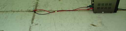


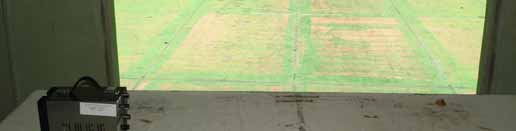
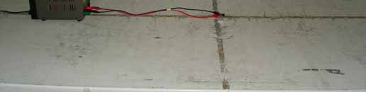
19 APPENDIX 1 - PHOTOGRAPHS OF TEST SETUP RADIATED EMISSION TEST END OF REPORT Page 19
FCC PART 15B CLASS A MEASUREMENT AND TEST REPORT
 FCC PART 15B CLASS A MEASUREMENT AND TEST REPORT For SAMBO HI TECH CO., LTD. 616-15, GANSUK4-DONG, NAMDONG-GU, INCHUN 405-810, KOREA Model: LSR700, SCI545HV1EF, SCI545HVEF This Report Concerns: Original
Measurement of RF Emissions from a Final Coat Electronics Corrosion Module
 Engineering Test Report No. 37802-02 Rev. A Measurement of RF Emissions from a Final Coat Electronics Corrosion Module For : Canadian Auto Preservation, Inc. 390 Bradwick Drive Concord, Ontario CANADA
EN 301 489-17 v1.2.1 TEST REPORT FOR. 802.11ag/Draft 802.11n WLAN PCI-E Mini Card MODEL NUMBER: BCM94322MC REPORT NUMBER: 07U11529-5
 EN 301 489-17 v1.2.1 TEST REPORT FOR 802.11ag/Draft 802.11n WLAN PCI-E Mini Card MODEL NUMBER: BCM94322MC REPORT NUMBER: 07U11529-5 ISSUE DATE: JANUARY 29, 2008 Prepared for BROADCOM CORPORATION 190 MATHILDA
Test Report. Prepared for: Technologic Systems, Inc. Model: TS-8820
 Test Report Prepared for: Technologic Systems, Inc. Model: TS-8820 Description: Single Board Computer with Analog and Digital Inputs and Outputs, Relays, and RS-232/485 Ports To IEC 61000-6-1 (2005-03)
FCC PART 15 SUBPART C EMI MEASUREMENT AND TEST REPORT
 FCC PART 15 SUBPART C EMI MEASUREMENT AND TEST REPORT For AeroComm, Inc. 10981 Eicher Drive Lenexa, KS 66219 2003-05-22 This Report Concerns: Original Report Equipment Type: 900MHz Transceiver Test Engineer:
MYRICOM, INC. TEST REPORT FOR THE SERVER RACK, 10G-PCIE2-8B2-2S & 10G-PCIE2-8B2-2QP FCC PART 15 SUBPART B SECTIONS 15.107 AND 15.109 CLASS A TESTING
 TESTING CERT #803.01, 803.02, 803.05, 803.06 MYRICOM, INC. TEST REPORT FOR THE SERVER RACK, 10G-PCIE2-8B2-2S & 10G-PCIE2-8B2-2QP FCC PART 15 SUBPART B SECTIONS 15.107 AND 15.109 CLASS A TESTING DATE OF
Rated Power(W) 8W 2. EG-LED0840-01 8W 3. EG-LED1027-01 10W
 8W 2. EG-LED0840-01 8W 3. EG-LED1027-01 10W") 14713221 001 Seite 2 von 37 Page 2 of 37 Model List: No Model Rated Voltage(V) 1. EG-LED0827-01 Rated Power(W) 8W 2. EG-LED0840-01 8W 3. EG-LED1027-01 10W 4. EG-LED1040-01 AC 100-240V, 10W 5. EG-LED1027-02
14713221 001 Seite 2 von 37 Page 2 of 37 Model List: No Model Rated Voltage(V) 1. EG-LED0827-01 Rated Power(W) 8W 2. EG-LED0840-01 8W 3. EG-LED1027-01 10W 4. EG-LED1040-01 AC 100-240V, 10W 5. EG-LED1027-02
Electromagnetic Compatibility Test Report. DC DC umodule Regulator LTM4613
 Report No.: 0000091428 31160742.001 Page 1 of 36 Electromagnetic Compatibility Test Report Prepared in accordance with EN 55022: 2006, +A1: 2007 On DC DC umodule Regulator LTM4613 For Linear Technology
Electromagnetic Compatibility Test Report Test results of Floww equipment
 Electromagnetic Compatibility Test Report Test results of Floww equipment Reference number Status test report Brand Model number : 10C00357RPT01.doc : Final : Floww : mobilefloww screenfloww pocketfloww
Declaration of Conformity.
 Declaration of Conformity. Type of equipment: Brand Name /Trade Mark: Type designation /model: Applicant: Network Camera SAMSUNG SND6011RP SAMSUNG TECHWIN CO., LTD. In accordance with the following Directives:
Declaration of Conformity.
 Declaration of Conformity. Type of equipment: Brand Name /Trade Mark: Type designation /model: Applicant: PTZ CAMERA SAMSUNG SCP2371HP SAMSUNG TECHWIN CO., LTD. In accordance with the following Directives:
EMC TEST REPORT For. Webcam. Model Number: CAM67U
 EMC TEST REPORT For Webcam Model Number: CAM67U Prepared for : Gembird Europe B.V. Wittevrouwen 56, 1358CD Almere, The Netherlands. Phone: +31-36-5211588 Prepared By : Shenzhen Meihua Electronic Technology
Declaration of Conformity.
 Declaration of Conformity. Type of equipment: Brand Name /Trade Mark: Type designation /model: Applicant: Network Camera SAMSUNG SNO-6011RP SAMSUNG TECHWIN CO., LTD. In accordance with the following Directives:
Prepared for Dorman Long Engineering Technology Consultant (Shanghai) Co., Ltd.
 Co., Ltd.") www.ecmg-global.com EMC TEST REPORT On Model Name: DL-P40 Computer Control System Model Number: Release 3.0 Hardware and Software Brand Name: Dorman Long Technology Ltd. Trade Mark: DLT Prepared for Dorman
www.ecmg-global.com EMC TEST REPORT On Model Name: DL-P40 Computer Control System Model Number: Release 3.0 Hardware and Software Brand Name: Dorman Long Technology Ltd. Trade Mark: DLT Prepared for Dorman
SHENZHEN GEMBIRD ELECTRONICS LTD EMC REPORT
 Shenzhen BST Technology Co., Ltd. SHENZHEN GEMBIRD ELECTRONICS LTD EMC REPORT Prepared For : Product Name: Model : Prepared By : SHENZHEN GEMBIRD ELECTRONICS LTD 5th Floor, Building B, Shifeng Industry
Test Report #: 1981-3 Date: April 8, 2005
 Test Report #: 1981-3 Date: April 8, 2005 CERTIFICATE #2316.01 Issued To: Bill Burks American Power Conversion 85 Rangeway Road North Billerica, MA 01862 USA 978-670-2440 Product Name/Description Model
MYRICOM, INC. TEST REPORT FOR THE LAN INTERFACE CARD, M3F2-PCIXE-2
 MYRICOM, INC. TEST REPORT FOR THE LAN INTERFACE CARD, M3F2-PCIXE-2 EN55024 (1998), EN61000-3-2 (2001), EN61000-3-3 (1995 W/A1: 98), EN55022 (1998) CLASS A, CISPR 22 (1997) CLASS A & FCC PART 15 SUBPART
Report Of. Shielding Effectiveness Test For. SafeSleeve Radiation Shielding Technology. Test Date(s): June 07 June 09, 2015
: June 07 June 09, 2015") Report Of Shielding Effectiveness Test For SafeSleeve Radiation Shielding Technology Test Date(s): June 07 June 09, 2015 Issue Date: June 10, 2015 UST Project No: 15-0137 Total Number of Pages Contained
Report Of Shielding Effectiveness Test For SafeSleeve Radiation Shielding Technology Test Date(s): June 07 June 09, 2015 Issue Date: June 10, 2015 UST Project No: 15-0137 Total Number of Pages Contained
Declaration of Conformity.
 Declaration of Conformity. Type of equipment: Brand Name /Trade Mark: Type designation /model: Applicant: Network Camera SAMSUNG SNP-6200RHP SAMSUNG TECHWIN CO., LTD. In accordance with the following Directives:
TEST REPORT FROM RFI GLOBAL SERVICES LTD
 FROM RFI GLOBAL SERVICES LTD Partial Test of: BTM411 To: EN 300 328 V1.7.1 (2006-10) Test Report Serial No: RFI/RPT1/RP76018JD01A This Test Report Is Issued Under The Authority Of Brian Watson, Operations
Declaration of Conformity.
 Declaration of Conformity. Type of equipment Brand Name /Trade Mark Type designation /model Applicant Network Camera SAMSUNG SND-5083P SAMSUNG TECHWIN CO., LTD. In accordance with the following Directives
RAPPORTO DI PROVA / TEST REPORT
 RAPPORTO DI PROVA / TEST REPORT Rif./Ref.No. FCCTR_130738-0 Data / Date: 17/09/2013 Pagine / Pages : 15 Scopo delle prove /Test object : Richiedente / Applicant : Persona di riferimento / Applicant s referee
Declaration of Conformity.
 Declaration of Conformity. Type of equipment: Brand Name /Trade Mark: Type designation /model: Applicant: PTZ CAMERA SAMSUNG SNP-5300P SAMSUNG TECHWIN CO., LTD. In accordance with the following Directives:
CONDUCTED EMISSION MEASUREMENT OF A CELL PHONE PROCESSOR MODULE
 Progress In Electromagnetics esearch C, Vol. 42, 191 203, 2013 CONDUCTED EMISSION MEASUEMENT OF A CELL PHONE POCESSO MODULE Fayu Wan *, Junxiang Ge, and Mengxiang Qu Nanjing University of Information Science
Test result: SHENZHEN TIMEWAY TECHNOLOGY CONSULTING CO LTD. ISO/IEC17025Accredited Lab. Report No: FCC 1106180 File reference No: 2011-07-18
 Report No: FCC 1106180 File reference No: 2011-07-18 ISO/IEC17025Accredited Lab. Applicant: FUJIAN NAN AN BAOFENG ELECTRONICS CO., LTD Product: Model No: Trademark: Two Way Radio UV-3R BAOFENG Test Standards:
EMC STANDARDS STANDARDS AND STANDARD MAKING BODIES. International. International Electrotechnical Commission (IEC) http://www.iec.
 http://www.iec.") EMC STANDARDS The EMC standards that a particular electronic product must meet depend on the product application (commercial or military) and the country in which the product is to be used. These EMC regulatory
EMC STANDARDS The EMC standards that a particular electronic product must meet depend on the product application (commercial or military) and the country in which the product is to be used. These EMC regulatory
EMC TEST REPORT For. Shenzhen Homelux Security Equipment Co., Ltd. Auto Dialer. Model No.: HX-GD20
 EMC TEST REPORT For Shenzhen Homelux Security Equipment Co., Ltd Auto Dialer Model No.: HX-GD20 Prepared for : Shenzhen Homelux Security Equipment Co., Ltd Address : 4 th Floor, Building 5, Jiademaluan
Agilent N8973A, N8974A, N8975A NFA Series Noise Figure Analyzers. Data Sheet
 Agilent N8973A, N8974A, N8975A NFA Series Noise Figure Analyzers Data Sheet Specifications Specifications are only valid for the stated operating frequency, and apply over 0 C to +55 C unless otherwise
TEST REPORT EN 55014-2 (1997) +A1 (2001)
 +A1 (2001)") Page 1 of 23 TEST REPORT EN 55014-2 (1997) +A1 (2001) Electromagnetic compatibility - Requirements for household appliances, electric tools and similar apparatus Part 2: Immunity Report Reference No....
Page 1 of 23 TEST REPORT EN 55014-2 (1997) +A1 (2001) Electromagnetic compatibility - Requirements for household appliances, electric tools and similar apparatus Part 2: Immunity Report Reference No....
Design and Certification of ASH Radio Systems for Japan
 Design and Certification of ASH Radio Systems for Japan RFM s second-generation ASH radio hybrids are being used in a wide variety of applications in Japan, operating under the Japanese BIJAKU radio regulations.
CERTIFICATE. Issued Date:May. 18, 2006 Report No.: 065L043-IT-CE-P07V03. MGate MB318n(-T) (n=0~9,a~z)
 (n=0~9,a~z)") CERTIFICATE Issued Date:May. 18, 2006 Report No.: 065L043-IT-CE-P07V03 This is to certify that the following designated product Product Trade name Model Number : 1 Port Device Server : Moxa : NPort 5150(-T),
CERTIFICATE Issued Date:May. 18, 2006 Report No.: 065L043-IT-CE-P07V03 This is to certify that the following designated product Product Trade name Model Number : 1 Port Device Server : Moxa : NPort 5150(-T),
SGS-CSTC Standards Technical Services (Shanghai) Co., Ltd.
 Co., Ltd.") 588 West Jindu Road,Songjiang District,Shanghai,China Telephone: +86 (0) 21 6191 5666 Fax: +86 (0) 21 6191 5678 ee.shanghai@sgs.com Page: 1 of 23 1 Cover Page Application No.: Applicant: Manufacturer:
588 West Jindu Road,Songjiang District,Shanghai,China Telephone: +86 (0) 21 6191 5666 Fax: +86 (0) 21 6191 5678 ee.shanghai@sgs.com Page: 1 of 23 1 Cover Page Application No.: Applicant: Manufacturer:
Standard: EN 61000-4-2 :1995, EN 61000-4-3 :1996, ENV 50204 :1993, & EN 61000-4-4 :1995 Solid State Energy Meter
 Standard: EN 61000-4-2 :1995, EN 61000-4-3 :1996, ENV 50204 :1993, & EN 61000-4-4 :1995 Model: Solid State Energy Meter Prepared for: Analog Devices, Inc. 804 Woburn Street Wilmington, MA 01887 Date of
RX-AM4SF Receiver. Pin-out. Connections
 RX-AM4SF Receiver The super-heterodyne receiver RX-AM4SF can provide a RSSI output indicating the amplitude of the received signal: this output can be used to create a field-strength meter capable to indicate
Correlation between OATS, Fully Anechoic Room and GTEM Radiated Emissions
 Correlation between OATS, Fully Anechoic Room and GTEM Radiated Emissions Stephen Clay Introduction: Just a few words about myself. My name is Steve Clay and I work for Nokia Mobile Phones, and it is my
TEST REPORT Rapporto di prova EMC N 060406. Test facility site: via L. da Vinci, 92, Caravaggio (BG), Italy Sede laboratorio
, Italy Sede laboratorio") TEST REPORT Rapporto di prova EMC N 060406 EUT: Organic Carbon Analyzer Analiuzzatore Carbonio Organico Model: TOCMETER Serial N : TM602 Client: TRE-ESSE s.r.l. Cliente Piazzale Europa 8 16036 Recco (GE),
TEST REPORT Rapporto di prova EMC N 060406 EUT: Organic Carbon Analyzer Analiuzzatore Carbonio Organico Model: TOCMETER Serial N : TM602 Client: TRE-ESSE s.r.l. Cliente Piazzale Europa 8 16036 Recco (GE),
Outer Diameter 23 φ mm Face side Dimension 20.1 φ mm. Baffle Opening. Normal 0.5 Watts Maximum 1.0 Watts Sine Wave.
 1. MODEL: 23CR08FH-50ND 2 Dimension & Weight Outer Diameter 23 φ mm Face side Dimension 20.1 φ mm Baffle Opening 20.1 φ mm Height Refer to drawing Weight 4.0Grams 3 Magnet Materials Rare Earth Size φ 9.5
SIGNAL GENERATORS and OSCILLOSCOPE CALIBRATION
 1 SIGNAL GENERATORS and OSCILLOSCOPE CALIBRATION By Lannes S. Purnell FLUKE CORPORATION 2 This paper shows how standard signal generators can be used as leveled sine wave sources for calibrating oscilloscopes.
Applications in EMC testing. Outline. Antennas for EMC Testing. Terminology
 Antennas for EMC Testing Zhong Chen ETS-Lindgren 1301 Arrow Point Drive Cedar Park, TX 78613 Zhong.Chen@ets-lindgren.com Outline EMC Terms and Definitions Typical EMC Antennas Calibration of EMC Antennas
RoHS APPROVAL SHEET. ituner 12V/6.6A SERIES NO. (E17) EA10953A. ( ) Edac Power Electronics (Suzhou) Co., Ltd. 59 No.59, Chang Sheng Road, Sheng Pu,
 EA10953A. ( ) Edac Power Electronics (Suzhou) Co., Ltd. 59 No.59, Chang Sheng Road, Sheng Pu,") APPROVAL SHEET CUSTOMER ituner CUSTOMER P/N DESCRIPTION EDAC MODEL 12V/6.6A SERIES NO. (E17) EA10953A DATE 2010-06-22 REVISION 0 APPROVED DESIGN PREPARE RoHS CONCLUSION APPROVED CONDITON CUSTOMER S APP
APPROVAL SHEET CUSTOMER ituner CUSTOMER P/N DESCRIPTION EDAC MODEL 12V/6.6A SERIES NO. (E17) EA10953A DATE 2010-06-22 REVISION 0 APPROVED DESIGN PREPARE RoHS CONCLUSION APPROVED CONDITON CUSTOMER S APP
Radio Frequency Exposure Test Report
 Radio Frequency Exposure EN 62311 January 2008 Assessment of electronic and electrical equipment related to human exposure restrictions for electromagnetic fields (0Hz 300GHz) (IEC 62311:2007, modified)
VOLTAGE/CURRENT CALIBRATOR ISO-TECH ILC-421
 VOLTAGE/CURRENT CALIBRATOR ISO-TECH ILC-421 TABLE OF CONTENTS 1. FEATURES... 1 2. SPECIFICATIONS... 1 2-1 General Specifications...1 2-2 Electrical Specifications... 2 3. FRONT PANEL DESCRIPTION... 4 3-1
R&S ENY81-CA6 Coupling Network For radio disturbance and immunity measurements
 R&S ENY81-CA6 Coupling Network For radio disturbance and immunity measurements on telecommunications ports Test & Measurement Data Sheet 01.00 R&S ENY81-CA6 Coupling Network At a glance The R&S ENY81-CA6
AN003. Evaluation of Anechoic Chambers For EMC Measurements Using A CNE. Overview. CNE III 9kHz to 2GHz Conducted and radiated output
 Evaluation of Anechoic Chambers For EMC Measurements Using A CNE Overview Anechoic chambers are used for EMC testing primarily for radiated emissions (RE) and radiated immunity (RI) in the frequency range
TEST REPORT. CONCLUSION: The submitted sample was found to COMPLY with the test requirement
 TEST REPORT Applicant Address Shenzhen Gembird Electronics Ltd. 5F, Building B, Shi-Feng Industrial Zone, Hua-Ning Rd., Xin-Wei Village, Da-Lang Street, Long-Hua, Bao-An Area, Shenzhen 518109, Guangdong
RF data receiver super-reactive ASK modulation, low cost and low consumption ideal for Microchip HCS KEELOQ decoder/encoder family. 0.
 Receiver AC-RX2/CS RF data receiver super-reactive ASK modulation, low cost and low consumption ideal for Microchip HCS KEELOQ decoder/encoder family. Pin-out 38.1 3 Component Side 1 2 3 7 11 13 14 15
RADIO TEST REPORT. EN 300 440-2 SRD radio equipment to be used in the 1 GHz to 40 GHz frequency range. DAkkS - Registration number : D-PL-12092-01-01
 RADIO TEST REPORT SRD radio equipment to be used in the 1 GHz to 40 GHz frequency range Report Reference No.... : G0M-1206-2043-TEU440G-V01 Testing Laboratory... : Eurofins Product Service GmbH Address...
Radiated emission measurement of a cell phone processor module using TEM cell
 , pp.48-53 http://dx.doi.org/10.14257/astl.2013.28.09 Radiated emission measurement of a cell phone processor module using TEM cell Fayu Wan 1,2*, Qi Liu 3, Jian Shen 3, Jin Wang 3 and Nigel Linge 4 1
Digital Active Indoor Antenna SRT ANT 10 ECO
 Digital Active Indoor Antenna SRT ANT 10 ECO Picture similar User Manual Table of contents 1.0 INTRODUCTION 1 2.0 PACKAGE CONTENT 1 3.0 SAFETY NOTES 2 4.0 CONNECTING THE ANTENNA 2 1.0 INTRODUCTION Thank
UNDERSTANDING AND CONTROLLING COMMON-MODE EMISSIONS IN HIGH-POWER ELECTRONICS
 Page 1 UNDERSTANDING AND CONTROLLING COMMON-MODE EMISSIONS IN HIGH-POWER ELECTRONICS By Henry Ott Consultants Livingston, NJ 07039 (973) 992-1793 www.hottconsultants.com hott@ieee.org Page 2 THE BASIC
R&S R-Line Compact Test Chamber Precise measurements of radiated emissions of wireless terminals 800 MHz to 18 GHz
 Test & Measurement Data Sheet 02.00 R&S R-Line Compact Test Chamber Precise measurements of radiated emissions of wireless terminals 800 MHz to 18 GHz R&S R-Line Compact Test Chamber At a glance The R-Line
DVT913 TV CHANNEL CONVERTER
 Broadband Cable Networks 1(5) DVT913 TV CHANNEL CONVERTER General DVT913 is a TV Channel Converter for the DVX tend product family. It consists of an input down converter from to, a high selectivity part
ELECTROMAGNETIC COMPATIBILITY TEST. Report reference N R-255 EMC 2010
 ELECTROMAGNETIC COMPATIBILITY TEST Report reference N R-255 EMC 2010 Constructor. Address Reference person. C LUCE S.r.l. Via Marmolada 5/11 20060 Truccazzano (MI) Italy ---- Product....... Model......
Agilent N2717A Service Software Performance Verification and Adjustment Software for the Agilent ESA Spectrum Analyzers Product Overview
 Agilent N2717A Service Software Performance Verification and Adjustment Software for the Agilent ESA Spectrum Analyzers Product Overview Reduce your cost of ownership by minimizing time to calibrate and
Telephone- and leased line modem for industrial applications TD-36
 Telephone- and leased line modem for industrial applications TD-36 Modem for industrial PSTN- and leased line applications The TD-36 is an analogue V.34 PSTN modem as well as an industrial 2-wire leased
Coupling/Decoupling Networks (CDN)
") Coupling/Decoupling Networks (CDN) For immunity testing according to IEC / EN 61000-4-6 Immunity testing CDNs are the preferred coupling and decoupling devices, for reasons of test reproducibility and
Coupling/Decoupling Networks (CDN) For immunity testing according to IEC / EN 61000-4-6 Immunity testing CDNs are the preferred coupling and decoupling devices, for reasons of test reproducibility and
Predicting radiated emissions from cables in the RE02/RE102/DO- 160/SAE J113-41 test set up, using measured current in NEC and simple TX equations.
 Predicting radiated emissions from cables in the RE02/RE102/DO- 160/SAE J113-41 test set up, using measured current in NEC and simple TX equations. D. A. Weston RE02Tx.rep 14-6-2004 NARTE Certified EMC
For the following information
 For the following information Product : Motherboard Model Number : M5A78L-M/USB3 Brand : ASUS Ref. File No.: C1M1104201 Applicant : ASUSTEK Computer Inc. Manufacturer #1 : MainTek Computer (Suzhou) Co.,
EMC TEST REPORT. Page: 1 of 38. Reference No.: WT08010091-S-E
 Page: 1 of 38 EMC TEST REPORT Reference No. Applicant Address : WT08010091-S-E : Gembird Electronics Ltd. : Room 1709 A, News Building, #2 Shennan Zhong Lu, Shenzhen, China Equipment Under Test (EUT) :
Partial GSM TEST - REPORT
 EUROFINS PRODUCT SERVICE GMBH Partial GSM TEST - REPORT EN 301 511 GSM/GPRS/GPS tracking unit FOX-LT-IP Test report no.: G0M20904-2307-T-51 Eurofins Product Service GmbH Storkower Str. 38c, 15526 Reichenwalde,
Electromagnetic Compatibility and International Regulatory Approvals
 Electromagnetic Compatibility and International Regulatory Approvals Most countries have now implemented strict regulations regarding Electromagnetic Compatibility (EMC) for electronic devices. This paper
LAB 1 TECHNICAL DOC 3 IN ONE LAB DEVICE. Velleman Legen Heirweg 33 9890 Gavere Belgium
 LAB 1 TECHNICAL DOC 3 IN ONE LAB DEVICE Velleman Legen Heirweg 33 9890 Gavere Belgium SPECIFICATIONS DIGITAL MULTIMETER 3 1/2 backlit LCD Automatic polarity indication DC voltage 200mV to 600V in 5 steps
AN3353 Application note
 Application note IEC 61000-4-2 standard testing Introduction This Application note is addressed to technical engineers and designers to explain how STMicroelectronics protection devices are tested according
FIBRE-OPTICS POWER METER INSTRUCTION MANUAL
 FIBRE-OPTICS POWER METER INSTRUCTION MANUAL FIBRE-OPTICS POWER METER ELLMAX ELECTRONICS LTD. Unit 29, Leyton Business Centre, Etloe Road, Leyton, London E10 7BT, England Tel: 020-8539 0136 Fax: 020-8539
Uncertainty evaluations in EMC measurements
 Uncertainty evaluations in EMC measurements Carlo Carobbi Dipartimento di Elettronica e Telecomunicazioni Università degli Studi di Firenze Politecnico di Milano - 20 Feb. 2009 1 Non - reproducibility
EMI TEST REPORT. Product Name. Notebook Personal Computer. Model A770;A790. Applied by:
 EN55022 / CISPR 22 / AS/NZS CISPR 22 Class B EMI TEST REPORT of Product Name Notebook Personal Computer Model A770;A790 Applied by: MITAC Technology Corporation 4F, No.1, R&D Road 2, Hsinchu Science-Based
iva Cable & Antenna Analyzer
 iva Cable & Antenna Analyzer VSWR, Return Loss Measurement & Distance to Fault The iva Series Cable & Antenna Analyzer is an exciting new product from Kaelus that enables users to accurately measure VSWR/return
Amplifier for Small Magnetic and Electric Wideband Receiving Antennas (model AAA-1B)
") Amplifier for Small Magnetic and Electric Wideband Receiving Antennas (model AAA-1B) 1. Description and Specifications Contents 1.1 Description 1.2 1.2 Specifications 1.3 1.3 Tested parameters in production
Amplifier for Small Magnetic and Electric Wideband Receiving Antennas (model AAA-1B) 1. Description and Specifications Contents 1.1 Description 1.2 1.2 Specifications 1.3 1.3 Tested parameters in production
iva Cable & Antenna Analyzer
 iva Cable & Antenna Analyzer VSWR, Return Loss Measurement & Distance to Fault The iva Series Cable & Antenna Analyzer is an exciting new product from Kaelus that enables users to accurately measure VSWR/return
Technical Datasheet Scalar Network Analyzer Model 8003-10 MHz to 40 GHz
 Technical Datasheet Scalar Network Analyzer Model 8003-10 MHz to 40 GHz The Giga-tronics Model 8003 Precision Scalar Network Analyzer combines a 90 db wide dynamic range with the accuracy and linearity
Agilent E5100A Network Analyzer
 Agilent E5100A Network Analyzer Data Sheet These specifications are the performance standards or limits against which the instrument is tested. When shipped from the factory, the E5100A meets the specifications
COUPLING / DECOUPLING NETWORK (CDN) FOR UNSCREENED BALANCED PAIRS
 FOR UNSCREENED BALANCED PAIRS") IEC / EN 61000-4-6 specifies the design and performance of a range of coupling / decoupling networks (CDNs). Each CDN is specific to the type of cable and the intended signal carried on the cable. Teseq
IEC / EN 61000-4-6 specifies the design and performance of a range of coupling / decoupling networks (CDNs). Each CDN is specific to the type of cable and the intended signal carried on the cable. Teseq
CE Test Report. : Microchip Technology Inc. 2355 West Chandler Blvd., Chandler, Arizona 85224-6199, USA
 CE Test Report Equipment : IEEE 802.11b/g Wireless LAN module Brand Name : MICROCHIP Model No. : MRF24WG0MA/MB Standard : EN 300 328 V1.8.1 (2012-06) Operating Band : 2400 MHz 2483.5 MHz Applicant Manufacturer
Waveguide Access Point WGA631. Product Guide
 Waveguide Access Point Product Guide Waveguide Access Point Contents 1. Description............................ 3 2. Application............................ 3 3. Technical data... 4 4. Physical interfaces......................
FCC Part 15C Compliance Test Report
 Test Report no.: Cph_FCC_732_5.doc Date of Report: 14-8-27 Number of pages: 42 Customer s Contact person: Ole Soerensen Testing laboratory: Customer: Nokia Corporation FCC listing no.: IC recognition no.:
30 In Compliance October 2014 www.incompliancemag.com
 30 In Compliance October 2014 www.incompliancemag.com Medical Devices in a Wireless World BY IVAYLO TANKOV While wireless technology is now an integral component of a wide variety of manufactured products,
DDX 7000 & 8003. Digital Partial Discharge Detectors FEATURES APPLICATIONS
 DDX 7000 & 8003 Digital Partial Discharge Detectors The HAEFELY HIPOTRONICS DDX Digital Partial Discharge Detector offers the high accuracy and flexibility of digital technology, plus the real-time display
Broadband Telecommunications Drop Amplifier
 INSTALL SHEET BDA Broadband Telecommunications Drop Amplifier Introduction The Broadband Telecommunications Drop Amplifier (BDA) is a two-way, 1 GHz amplifier designed for customer-premise amplification
Regulatory requirements - USA
 Regulatory requirements - USA FCC CFR 47 Part 2 & 15 Radiospectrum and EMF Test on qualified laboratory Test methods different from EU Certification required TCB or FCC Grant Regulatory EMC requirements
CE Test Report. : BL600 Series Bluetooth Low Energy Module
 CE Test Report Equipment Brand Name Model No. : BL600 Series Bluetooth Low Energy Module : Laird Technologies : BL600-SA, BL600-SC, BL600-ST Additional Model No. : BL620-SA, BL620-SC, BL620-ST Standard
Pre-Compliance Test Method for Radiated Emissions of Automotive Components Using Scattering Parameter Transfer Functions
 PreCompliance Test Method for Radiated Emissions of Automotive Components Using Scattering Parameter Transfer Functions D. Schneider 1*, S. Tenbohlen 1, W. Köhler 1 1 Institute of Power Transmission and
Nardalert S3 Non-Ionizing Radiation Monitor
 Patent Pending Non-Ionizing Radiation Monitor Field Replaceable Sensor Modules Color LCD Display Multi-Color Alarm LED s USB Interface for Data and Charging Interchangeable Lanyard or Belt Clips Comprehensive
BioStation Mifare OC(BSM-OC) NONE. Receipt Date 21-Feb-08 Receipt Number. Issued Date 18-Mar-08 Tested Date
 NONE. Receipt Date 21-Feb-08 Receipt Number. Issued Date 18-Mar-08 Tested Date") Test Report for CE Report Number Applicant ESTCE0803-003 Company Name Address Product type Suprema Inc. 16F Parkview Office Tower, Jeongja-dong, Bundang-gu,Seongnam, Gyeonggi, 463-863 Korea FINGERPRINT
Test Report for CE Report Number Applicant ESTCE0803-003 Company Name Address Product type Suprema Inc. 16F Parkview Office Tower, Jeongja-dong, Bundang-gu,Seongnam, Gyeonggi, 463-863 Korea FINGERPRINT
AN1200.04. Application Note: FCC Regulations for ISM Band Devices: 902-928 MHz. FCC Regulations for ISM Band Devices: 902-928 MHz
 AN1200.04 Application Note: FCC Regulations for ISM Band Devices: Copyright Semtech 2006 1 of 15 www.semtech.com 1 Table of Contents 1 Table of Contents...2 1.1 Index of Figures...2 1.2 Index of Tables...2
Low-cost EMI Pre-compliance Testing Using a Spectrum Analyzer
 Low-cost EMI Pre-compliance Testing Using a Spectrum Analyzer Application Note EMI regulations are in place throughout the world to provide improved reliability and safety for users of electrical and electronic
TEST REPORT. Please refer to section 3 of this report which indicates which item was actually tested and which were electrically identical.
 198 Kezhu Road, Scientech Park, Guangzhou Economic & Technological Development District, Guangzhou, China 510663 Telephone: +86 (0) 20 82155555 Fax: +86 (0) 20 82075059 Email: sgs_internet_operations@sgs.com
AM Radio Field Strength Measurements with Confidence November 2004
 AM Radio Field Strength Measurements with Confidence November 2004 Understanding the AM Broadcast signal The AM Broadcast service in the United States and many other countries is implemented in 10 khz
Agilent AN 1316 Optimizing Spectrum Analyzer Amplitude Accuracy
 Agilent AN 1316 Optimizing Spectrum Analyzer Amplitude Accuracy Application Note RF & Microwave Spectrum Analyzers Table of Contents 3 3 4 4 5 7 8 8 13 13 14 16 16 Introduction Absolute versus relative
Coupling- / Decoupling Network. 150 khz 300 MHz. 150 khz 230 MHz. 10 khz 230 MHz. IEC 61000-4 - 6 and CISPR 15 / CISPR 22 IEC 61000-4 - 6
 Coupling- / Decoupling Network 150 khz 300 MHz IEC 61000-4 - 6 and CISPR 15 / CISPR 22 150 khz 230 MHz IEC 61000-4 - 6 10 khz 230 MHz IEC 61000-4 - 6 and IEC 61326-3 - 2 and NAMUR Coupling and decoupling
DDX 7000 & 8003. Digital Partial Discharge Detectors FEATURES APPLICATIONS
 DDX 7000 & 8003 Digital Partial Discharge Detectors The HAEFELY HIPOTRONICS DDX Digital Partial Discharge Detector offers the high accuracy and flexibility of digital technology, plus the real-time display
Impedance 50 (75 connectors via adapters)
") VECTOR NETWORK ANALYZER PLANAR TR1300/1 DATA SHEET Frequency range: 300 khz to 1.3 GHz Measured parameters: S11, S21 Dynamic range of transmission measurement magnitude: 130 db Measurement time per point:
VECTOR NETWORK ANALYZER PLANAR TR1300/1 DATA SHEET Frequency range: 300 khz to 1.3 GHz Measured parameters: S11, S21 Dynamic range of transmission measurement magnitude: 130 db Measurement time per point:
NI USB-5681 RF Power Meter Specifications
 NI USB-568 RF Power Meter Specifications General This document lists specifications for the NI USB-568 RF power meter. Minimum or maximum specifications are warranted under the following conditions: hour
USB Plus+ RFID Reader Setup Guide
 875-0042-03 RevA USB Plus+ RFID Reader Setup Guide 1 Government Limited Rights Notice: All documentation and manuals were developed at private expense and no part of it was developed using Government funds.
NI 9423. NI C Series Overview DATASHEET. 8-Channel Sinking Digital Input Module
 DATASHEET NI 9423 8-Channel Sinking Digital Input Module 8-channel, 100 µs digital input 24 V logic, sinking digital input Compatible with NI CompactDAQ counters 250 Vrms, CAT II isolation 10-position
Current Probes. User Manual
 Current Probes User Manual ETS-Lindgren L.P. reserves the right to make changes to any product described herein in order to improve function, design, or for any other reason. Nothing contained herein shall
Agilent P940xA/C Solid State PIN Diode Switches
 Agilent P940xA/C Solid State PIN Diode Switches Operating and Service Manual Agilent Technologies Notices Agilent Technologies, Inc. 2007 No part of this manual may be reproduced in any form or by any
Physical Specifications (Custom design available.)
") Helmholtz Coils A useful laboratory technique for getting a fairly uniform magnetic field, is to use a pair of circular coils on a common axis with equal currents flowing in the same sense. For a given
Helmholtz Coils A useful laboratory technique for getting a fairly uniform magnetic field, is to use a pair of circular coils on a common axis with equal currents flowing in the same sense. For a given
HP 70950B OPTICAL SPECTRUM ANALYZER
 HP 71450B, 71451B, and 71452B Optical Spectrum Analyzers Technical Specifications Spectral Measurements from 600 to 1700 nm HP 70950B OPTICAL SPECTRUM ANALYZER OPTICAL INPUT The HP 71450B, 71451B, and
Broadband over Power Line (BPL) Test Procedures and Equipment Authorization
 Test Procedures and Equipment Authorization") Broadband over Power Line (BPL) Test Procedures and Equipment Authorization Andy Leimer Equipment Authorization Branch Federal Communications Commission Office of Engineering and Technology Laboratory
Broadband over Power Line (BPL) Test Procedures and Equipment Authorization Andy Leimer Equipment Authorization Branch Federal Communications Commission Office of Engineering and Technology Laboratory
How To Power A Power Supply Shelf With A Power Unit (Hp 2920)
") Overview Models HP 640 Redundant/External Power Supply Shelf J9805A Key features Provides redundant or extenal power for HP 2920 Switch Series products Uses same modular power supplies as the HP 2920 Switches
Overview Models HP 640 Redundant/External Power Supply Shelf J9805A Key features Provides redundant or extenal power for HP 2920 Switch Series products Uses same modular power supplies as the HP 2920 Switches