MYRICOM, INC. TEST REPORT FOR THE SERVER RACK, 10G-PCIE2-8B2-2S & 10G-PCIE2-8B2-2QP FCC PART 15 SUBPART B SECTIONS AND CLASS A TESTING
|
|
|
- Irma Robertson
- 8 years ago
- Views:
Transcription
1 TESTING CERT #803.01, , , MYRICOM, INC. TEST REPORT FOR THE SERVER RACK, 10G-PCIE2-8B2-2S & 10G-PCIE2-8B2-2QP FCC PART 15 SUBPART B SECTIONS AND CLASS A TESTING DATE OF ISSUE: MARCH 25, 2009 PREPARED FOR: Myricom, Inc. 325 North Santa Anita Ave. Arcadia, CA PREPARED BY: Mary Ellen Clayton CKC Laboratories, Inc Sierra Pines Drive Mariposa, CA P.O. No.: Date of test: February 24 - March 2, 2009 W.O. No.: This report contains a total of 19 pages and may be reproduced in full only. Partial reproduction may only be done with the written consent of CKC Laboratories, Inc. The results in this report apply only to the items tested, as identified herein. Page 1 of 19

2 TABLE OF CONTENTS Administrative Information...3 Approvals...3 Site File Registration Numbers...3 Summary of Results...4 Conditions During Testing...4 Equipment Under Test (EUT) Description...4 Equipment Under Test...4 Peripheral Devices...4 Measurement Uncertainties...5 Report of Emissions Measurements...5 Testing Parameters...5 Conducted Emissions...7 Radiated Emissions...14 Page 2 of 19

3 ADMINISTRATIVE INFORMATION DATE OF TEST: February 24 - March 2, 2009 DATE OF RECEIPT: February 24, 2009 REPRESENTATIVE: Alan Kulawik MANUFACTURER: Myricom, Inc. 325 North Santa Anita Ave. Arcadia, CA TEST LOCATION: CKC Laboratories, Inc. 110 Olinda Place Brea, CA TEST METHOD: ANSI C63.4 (2003) PURPOSE OF TEST: To perform testing of the Server Rack, 10G-PCIE2-8B2-2S & 10G- PCIE2-8B2-2QP with the requirements for FCC Part 15 Subpart B Sections and Class A devices. APPROVALS QUALITY ASSURANCE: TEST PERSONNEL: Steve Behm, Director of Engineering Services Shamnderjit Hundal, Test Engineer SITE FILE REGISTRATION NUMBERS Location Japan Canada FCC Brea A R-2945, C-3248 & T D Page 3 of 19

4 SUMMARY OF RESULTS Test Specification Results Conducted Emissions FCC Part 15 Subpart B Section Class A Pass Radiated Emissions FCC Part 15 Subpart B Section Class A Pass CONDITIONS DURING TESTING No modifications to the EUT were necessary during testing. EQUIPMENT UNDER TEST (EUT) DESCRIPTION The customer declares the EUT tested by CKC Laboratories was representative of a production unit. EQUIPMENT UNDER TEST Server Rack Manuf: Myricom, Inc. Model: 10G-PCIE2-8B2-2QP Serial: NA Server Rack Manuf: Myricom, Inc. Model: 10G-PCIE2-8B2-2S Serial: NA PERIPHERAL DEVICES The EUT was tested with the following peripheral device(s): Mouse Manuf: Model: Serial: Monitor Manuf: Model: Serial: Lenovo NA NA MPC NA NA Keyboard Manuf: Lenovo Model: NA Serial: NA Page 4 of 19

5 MEASUREMENT UNCERTAINTIES Uncertainty Value Parameter 4.73 db Radiated Emissions 3.34 db Mains Conducted Emissions 3.30 db Disturbance Power The reported measurement uncertainties are calculated based on the worst case of all laboratory environments from CKC Laboratories, Inc. test sites. Only those parameters which require estimation of measurement uncertainty are reported. The reported worst case measurement uncertainty is less than the maximum values derived in CISPR Reported uncertainties represent expanded uncertainties expressed at approximately the 95% confidence level using a coverage factor of k=2. Compliance is deemed to occur provided measurements are below the specified limits. REPORT OF EMISSIONS MEASUREMENTS TESTING PARAMETERS The cables were routed consistent with the typical application by varying the configuration of the test sample. Interface cables were connected to the available ports of the test unit. The effect of varying the position of the cables was investigated to find the configuration that produced maximum emissions. Cables were of the type and length specified in the individual requirements. The length of cable that produced maximum emissions was selected. The equipment under test (EUT) was set up in a manner that represented its normal use, as shown in the setup photographs. Any special conditions required for the EUT to operate normally are identified in the comments that accompany the emissions tables. The emissions data was taken with a spectrum analyzer or receiver. Incorporating the applicable correction factors for distance, antenna, cable loss and amplifier gain, the data was reduced as shown in the table below. The corrected data was then compared to the applicable emission limits. Preliminary and final measurements were taken in order to ensure that all emissions from the EUT were found and maximized. CORRECTION FACTORS The basic spectrum analyzer reading was converted using correction factors as shown in the highest emissions readings in the tables. For radiated emissions in dbµv/m, the spectrum analyzer reading in dbµv was corrected by using the following formula. This reading was then compared to the applicable specification limit. Page 5 of 19

6 SAMPLE CALCULATIONS Meter reading (dbµv) + Antenna Factor (db) + Cable Loss (db) - Distance Correction (db) - Preamplifier Gain (db) = Corrected Reading (dbµv/m) TEST INSTRUMENTATION AND ANALYZER SETTINGS The test instrumentation and equipment listed were used to collect the emissions data. A spectrum analyzer or receiver was used for all measurements. The following table shows the measuring equipment bandwidth settings that were used in designated frequency bands. For testing emissions, an appropriate reference level and a vertical scale size of 10 db per division were used. When conducted emissions testing was performed, a 10 db external attenuator was used with internal offset correction in the analyzer. MEASURING EQUIPMENT BANDWIDTH SETTINGS PER FREQUENCY RANGE TEST BEGINNING FREQUENCY ENDING FREQUENCY BANDWIDTH SETTING CONDUCTED EMISSIONS 150 khz 30 MHz 9 khz RADIATED EMISSIONS 30 MHz 1000 MHz 120 khz RADIATED EMISSIONS 1000 MHz >1 GHz 1 MHz SPECTRUM ANALYZER/RECEIVER DETECTOR FUNCTIONS The notes that accompany the measurements contained in the emissions tables indicate the type of detector function used to obtain the given readings. Unless otherwise noted, all readings were made in the "Peak" mode. Whenever a "Quasi-Peak" or "Average" reading is listed as one of the highest readings, this is indicated as a "QP" or an "Ave" on the appropriate rows of the data sheets. The following paragraphs describe in more detail the detector functions and when they were used to obtain the emissions data. Peak In this mode, the spectrum analyzer/receiver readings recorded all emissions at their peak value as the frequency band selected was scanned. By combining this function with another feature of the measuring device called "peak hold," the measuring device had the ability to measure transients or low duty cycle transient emission peak levels. In this mode the measuring device made a slow scan across the frequency band selected and measured the peak emission value found at each frequency across the band. Quasi-Peak When the true peak values exceeded or were within 2 db of the specification limit, quasi-peak measurements were taken using the quasi-peak detector. Average For certain frequencies, average measurements may be made using the spectrum analyzer/receiver. To make these measurements, the test engineer reduces the video bandwidth on the measuring device until the modulation of the signal is filtered out. At this point the measuring device is set into the linear mode and the scan time is reduced. Page 6 of 19

7 CONDUCTED EMISSIONS Test Setup Photos Page 7 of 19

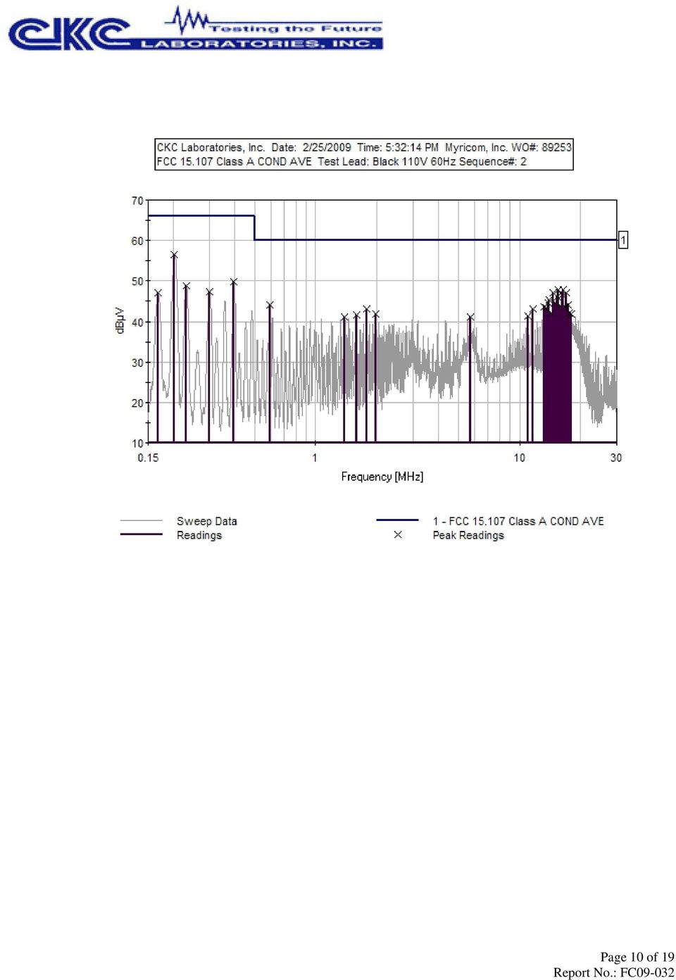
8 Test Data Sheets Test Location: CKC Laboratories, Inc N. Olinda Place. Brea, CA (714) Customer: Myricom, Inc. Specification: FCC Class A COND AVE Work Order #: Date: 2/25/2009 Test Type: Conducted Emissions Time: 5:32:14 PM Equipment: Server Rack Sequence#: 2 Manufacturer: Myricom, Inc. Tested By: S.Hundal Model: 10G-PCIE2-8B2-2QP & 10G-PCIE2-8B2-110V 60Hz 2S S/N: NA Test Equipment: Function S/N Calibration Date Cal Due Date Asset # Spectrum Analyzer US /23/ /23/ LISN /09/ /09/ dB Attenuator None 10/14/ /14/2010 P kHz HPF G /09/ /09/ Conducted Emission Cable Cable #21 05/12/ /12/2010 P04358 Equipment Under Test (* = EUT): Function Manufacturer Model # S/N Server rack Myricom, Inc. 10G-PCIE2-8B2-2QP NA Server rack Myricom, Inc. 10G-PCIE2-8B2-2S NA Support Devices: Function Manufacturer Model # S/N Mouse Lenovo NA NA Keyboard Lenovo NA NA Monitor MPC NA NA Test Conditions / Notes: The two EUTs are plugged into slots in the computer. The computer is hooked up to a monitor, keyboard and mouse. Transducer Legend: T1=150kHz HPF AN02610_ T3=Cable #21 -P Site A 05/12/10 T2=6dB atten-p trn T4=L1 Insertion Loss AN00847_ Measurement Data: Reading listed by margin. Test Lead: Black # Freq Rdng T1 T2 T3 T4 Dist Corr Spec Margin Polar MHz dbµv db db db db Table dbµv dbµv db Ant k Black M Black M Black M Black Page 8 of 19

9 M Black M Black M Black M Black M Black M Black k Black M Black M Black k Black M Black M Black M Black M Black M Black k Black M Black M Black M Black M Black M Black k Black M Black M Black M Black k Black Page 9 of 19

10 Page 10 of 19
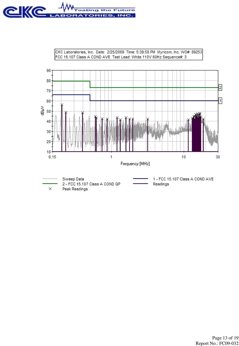
11 Test Location: CKC Laboratories, Inc N. Olinda Place. Brea, CA (714) Customer: Myricom, Inc. Specification: FCC Class A COND AVE Work Order #: Date: 2/25/2009 Test Type: Conducted Emissions Time: 5:39:58 PM Equipment: Server Rack Sequence#: 3 Manufacturer: Myricom, Inc. Tested By: S.Hundal Model: 10G-PCIE2-8B2-2QP & 10G-PCIE2-110V 60Hz 8B2-2S S/N: NA Test Equipment: Function S/N Calibration Date Cal Due Date Asset # Spectrum Analyzer US /23/ /23/ LISN /09/ /09/ dB Attenuator None 10/14/ /14/2010 P kHz HPF G /09/ /09/ Conducted Emission Cable Cable #21 05/12/ /12/2010 P04358 Equipment Under Test (* = EUT): Function Manufacturer Model # S/N Server rack Myricom, Inc. 10G-PCIE2-8B2-2QP NA Server rack Myricom, Inc. 10G-PCIE2-8B2-2S NA Support Devices: Function Manufacturer Model # S/N Mouse Lenovo NA NA Keyboard Lenovo NA NA Monitor MPC NA NA Test Conditions / Notes: The two EUTs are plugged into slots in the computer. The computer is hooked up to a monitor, keyboard and mouse. Transducer Legend: T1=150kHz HPF AN02610_ T3=Cable #21 -P Site A 05/12/10 T2=6dB atten-p trn T4=L2 Insertion Loss AN00847_ Measurement Data: Reading listed by margin. Test Lead: White # Freq Rdng T1 T2 T3 T4 Dist Corr Spec Margin Polar MHz dbµv db db db db Table dbµv dbµv db Ant k White M White M White M White Page 11 of 19

12 M White M White M White M White M White k White M White M White M White M White M White M White k White k White M White M White k White k White M White M White M White M White k White M White M White M White Page 12 of 19

13 Page 13 of 19
14 RADIATED EMISSIONS Test Setup Photos Page 14 of 19

15 Test Data Sheets Test Location: CKC Laboratories, Inc N. Olinda Place. Brea, CA (714) Customer: Myricom, Inc. Specification: FCC Class A Work Order #: Date: 3/2/2009 Test Type: Maximized Emissions Time: 22:20:18 Equipment: Server Rack Sequence#: 1 Manufacturer: Myricom, Inc. Tested By: S.Hundal Model: 10G-PCIE2-8B2-2QP & 10G-PCIE2-8B2-2S S/N: NA Test Equipment: Function S/N Calibration Date Cal Due Date Asset # Spectrum Analyzer US /23/ /23/ Bilog Antenna /21/ /21/ Pre amp to SA Cable Cable #10 05/16/ /16/2009 P05050 Cable Cable15 01/05/ /05/2011 P05198 Pre Amp 1937A /02/ /02/ Heliax Antenna Cable P /04/ /04/2010 P05565 Microwave Pre-amp 3123A /28/ /28/ Horn Antenna /06/ /06/ GHz Horn /21/ /21/ GHz cable NA 09/18/ /18/2009 P02946 Equipment Under Test (* = EUT): Function Manufacturer Model # S/N Server rack Myricom, Inc. 10G-PCIE2-8B2-2QP NA Server rack Myricom, Inc. 10G-PCIE2-8B2-2S NA Support Devices: Function Manufacturer Model # S/N Mouse Lenovo NA NA Keyboard Lenovo NA NA Monitor MPC NA NA Test Conditions / Notes: The two EUTs are plugged into slots in the computer. The computer is hooked up to a monitor, keyboard and mouse. Page 15 of 19

16 Transducer Legend: T1=Bilog-AN01995 BILOG_ T3=Cable #15_05198_ Site A, T5=Heliax Cable 54' ANP T7=Horn Ant AN T9=CAB-ANP T2=Cable #10_P05050_ T4=Pre_amp_HP8447D-AN T6=HF_pre AMP-1-26GHz_AN TRN T8=ANT 18-26GHz Horn AN01413 Measurement Data: Reading listed by margin. Test Distance: 3 Meters # Freq Rdng T1 T2 T3 T4 Dist Corr Spec Margin Polar T5 T9 T6 T7 T8 MHz dbµv db db db db Table dbµv/m dbµv/m db Ant M Vert M Vert M Vert M Horiz M Horiz M Vert M Vert M Vert M Vert M Horiz M Vert M Horiz M Vert Page 16 of 19

17 M Horiz M Horiz M Horiz M Vert M Vert M Vert M Vert M Vert M Vert M Horiz M Vert M Horiz M Vert M Vert M Vert M Vert M Vert Page 17 of 19

18 M Horiz M Horiz M Horiz M Vert M Vert M Horiz M Horiz M Vert M Vert M Horiz M Horiz M Horiz M Vert M Horiz M Vert M Horiz M Vert Page 18 of 19

19 M Vert M M Vert Vert M Vert M Vert M Horiz M Vert M Vert M Horiz M Vert M Horiz M Horiz M Horiz M Horiz Page 19 of 19

MYRICOM, INC. TEST REPORT FOR THE LAN INTERFACE CARD, M3F2-PCIXE-2
 MYRICOM, INC. TEST REPORT FOR THE LAN INTERFACE CARD, M3F2-PCIXE-2 EN55024 (1998), EN61000-3-2 (2001), EN61000-3-3 (1995 W/A1: 98), EN55022 (1998) CLASS A, CISPR 22 (1997) CLASS A & FCC PART 15 SUBPART
Measurement of RF Emissions from a Final Coat Electronics Corrosion Module
 Engineering Test Report No. 37802-02 Rev. A Measurement of RF Emissions from a Final Coat Electronics Corrosion Module For : Canadian Auto Preservation, Inc. 390 Bradwick Drive Concord, Ontario CANADA
FCC PART 15B CLASS A MEASUREMENT AND TEST REPORT
 FCC PART 15B CLASS A MEASUREMENT AND TEST REPORT For SAMBO HI TECH CO., LTD. 616-15, GANSUK4-DONG, NAMDONG-GU, INCHUN 405-810, KOREA Model: LSR700, SCI545HV1EF, SCI545HVEF This Report Concerns: Original
Electromagnetic Compatibility Test Report Test results of Floww equipment
 Electromagnetic Compatibility Test Report Test results of Floww equipment Reference number Status test report Brand Model number : 10C00357RPT01.doc : Final : Floww : mobilefloww screenfloww pocketfloww
EN 301 489-17 v1.2.1 TEST REPORT FOR. 802.11ag/Draft 802.11n WLAN PCI-E Mini Card MODEL NUMBER: BCM94322MC REPORT NUMBER: 07U11529-5
 EN 301 489-17 v1.2.1 TEST REPORT FOR 802.11ag/Draft 802.11n WLAN PCI-E Mini Card MODEL NUMBER: BCM94322MC REPORT NUMBER: 07U11529-5 ISSUE DATE: JANUARY 29, 2008 Prepared for BROADCOM CORPORATION 190 MATHILDA
FCC PART 15 SUBPART C EMI MEASUREMENT AND TEST REPORT
 FCC PART 15 SUBPART C EMI MEASUREMENT AND TEST REPORT For AeroComm, Inc. 10981 Eicher Drive Lenexa, KS 66219 2003-05-22 This Report Concerns: Original Report Equipment Type: 900MHz Transceiver Test Engineer:
RADIO TEST REPORT. EN 300 440-2 SRD radio equipment to be used in the 1 GHz to 40 GHz frequency range. DAkkS - Registration number : D-PL-12092-01-01
 RADIO TEST REPORT SRD radio equipment to be used in the 1 GHz to 40 GHz frequency range Report Reference No.... : G0M-1206-2043-TEU440G-V01 Testing Laboratory... : Eurofins Product Service GmbH Address...
Test Report. Prepared for: Technologic Systems, Inc. Model: TS-8820
 Test Report Prepared for: Technologic Systems, Inc. Model: TS-8820 Description: Single Board Computer with Analog and Digital Inputs and Outputs, Relays, and RS-232/485 Ports To IEC 61000-6-1 (2005-03)
Test result: SHENZHEN TIMEWAY TECHNOLOGY CONSULTING CO LTD. ISO/IEC17025Accredited Lab. Report No: FCC 1106180 File reference No: 2011-07-18
 Report No: FCC 1106180 File reference No: 2011-07-18 ISO/IEC17025Accredited Lab. Applicant: FUJIAN NAN AN BAOFENG ELECTRONICS CO., LTD Product: Model No: Trademark: Two Way Radio UV-3R BAOFENG Test Standards:
RAPPORTO DI PROVA / TEST REPORT
 RAPPORTO DI PROVA / TEST REPORT Rif./Ref.No. FCCTR_130738-0 Data / Date: 17/09/2013 Pagine / Pages : 15 Scopo delle prove /Test object : Richiedente / Applicant : Persona di riferimento / Applicant s referee
TEST REPORT EN 55014-2 (1997) +A1 (2001)
 +A1 (2001)") Page 1 of 23 TEST REPORT EN 55014-2 (1997) +A1 (2001) Electromagnetic compatibility - Requirements for household appliances, electric tools and similar apparatus Part 2: Immunity Report Reference No....
Page 1 of 23 TEST REPORT EN 55014-2 (1997) +A1 (2001) Electromagnetic compatibility - Requirements for household appliances, electric tools and similar apparatus Part 2: Immunity Report Reference No....
Electromagnetic Compatibility Test Report. DC DC umodule Regulator LTM4613
 Report No.: 0000091428 31160742.001 Page 1 of 36 Electromagnetic Compatibility Test Report Prepared in accordance with EN 55022: 2006, +A1: 2007 On DC DC umodule Regulator LTM4613 For Linear Technology
TEST REPORT FROM RFI GLOBAL SERVICES LTD
 FROM RFI GLOBAL SERVICES LTD Partial Test of: BTM411 To: EN 300 328 V1.7.1 (2006-10) Test Report Serial No: RFI/RPT1/RP76018JD01A This Test Report Is Issued Under The Authority Of Brian Watson, Operations
Rated Power(W) 8W 2. EG-LED0840-01 8W 3. EG-LED1027-01 10W
 8W 2. EG-LED0840-01 8W 3. EG-LED1027-01 10W") 14713221 001 Seite 2 von 37 Page 2 of 37 Model List: No Model Rated Voltage(V) 1. EG-LED0827-01 Rated Power(W) 8W 2. EG-LED0840-01 8W 3. EG-LED1027-01 10W 4. EG-LED1040-01 AC 100-240V, 10W 5. EG-LED1027-02
14713221 001 Seite 2 von 37 Page 2 of 37 Model List: No Model Rated Voltage(V) 1. EG-LED0827-01 Rated Power(W) 8W 2. EG-LED0840-01 8W 3. EG-LED1027-01 10W 4. EG-LED1040-01 AC 100-240V, 10W 5. EG-LED1027-02
Agilent AN 1316 Optimizing Spectrum Analyzer Amplitude Accuracy
 Agilent AN 1316 Optimizing Spectrum Analyzer Amplitude Accuracy Application Note RF & Microwave Spectrum Analyzers Table of Contents 3 3 4 4 5 7 8 8 13 13 14 16 16 Introduction Absolute versus relative
Broadband over Power Line (BPL) Test Procedures and Equipment Authorization
 Test Procedures and Equipment Authorization") Broadband over Power Line (BPL) Test Procedures and Equipment Authorization Andy Leimer Equipment Authorization Branch Federal Communications Commission Office of Engineering and Technology Laboratory
Broadband over Power Line (BPL) Test Procedures and Equipment Authorization Andy Leimer Equipment Authorization Branch Federal Communications Commission Office of Engineering and Technology Laboratory
EMC TEST REPORT For. Webcam. Model Number: CAM67U
 EMC TEST REPORT For Webcam Model Number: CAM67U Prepared for : Gembird Europe B.V. Wittevrouwen 56, 1358CD Almere, The Netherlands. Phone: +31-36-5211588 Prepared By : Shenzhen Meihua Electronic Technology
AN1200.04. Application Note: FCC Regulations for ISM Band Devices: 902-928 MHz. FCC Regulations for ISM Band Devices: 902-928 MHz
 AN1200.04 Application Note: FCC Regulations for ISM Band Devices: Copyright Semtech 2006 1 of 15 www.semtech.com 1 Table of Contents 1 Table of Contents...2 1.1 Index of Figures...2 1.2 Index of Tables...2
Prepared for Dorman Long Engineering Technology Consultant (Shanghai) Co., Ltd.
 Co., Ltd.") www.ecmg-global.com EMC TEST REPORT On Model Name: DL-P40 Computer Control System Model Number: Release 3.0 Hardware and Software Brand Name: Dorman Long Technology Ltd. Trade Mark: DLT Prepared for Dorman
www.ecmg-global.com EMC TEST REPORT On Model Name: DL-P40 Computer Control System Model Number: Release 3.0 Hardware and Software Brand Name: Dorman Long Technology Ltd. Trade Mark: DLT Prepared for Dorman
Report Of. Shielding Effectiveness Test For. SafeSleeve Radiation Shielding Technology. Test Date(s): June 07 June 09, 2015
: June 07 June 09, 2015") Report Of Shielding Effectiveness Test For SafeSleeve Radiation Shielding Technology Test Date(s): June 07 June 09, 2015 Issue Date: June 10, 2015 UST Project No: 15-0137 Total Number of Pages Contained
Report Of Shielding Effectiveness Test For SafeSleeve Radiation Shielding Technology Test Date(s): June 07 June 09, 2015 Issue Date: June 10, 2015 UST Project No: 15-0137 Total Number of Pages Contained
DSA800 Series Spectrum Analyzer
 DSA800 Series Spectrum Analyzer Configuration Guide This guide is used to help users to configure DSA800 series spectrum analyzer according to their requirements. You can get an overall understanding of
Declaration of Conformity.
 Declaration of Conformity. Type of equipment: Brand Name /Trade Mark: Type designation /model: Applicant: Network Camera SAMSUNG SND6011RP SAMSUNG TECHWIN CO., LTD. In accordance with the following Directives:
Low-cost EMI Pre-compliance Testing Using a Spectrum Analyzer
 Low-cost EMI Pre-compliance Testing Using a Spectrum Analyzer Application Note EMI regulations are in place throughout the world to provide improved reliability and safety for users of electrical and electronic
Regulatory requirements - USA
 Regulatory requirements - USA FCC CFR 47 Part 2 & 15 Radiospectrum and EMF Test on qualified laboratory Test methods different from EU Certification required TCB or FCC Grant Regulatory EMC requirements
EMC TEST REPORT. Page: 1 of 38. Reference No.: WT08010091-S-E
 Page: 1 of 38 EMC TEST REPORT Reference No. Applicant Address : WT08010091-S-E : Gembird Electronics Ltd. : Room 1709 A, News Building, #2 Shennan Zhong Lu, Shenzhen, China Equipment Under Test (EUT) :
AN003. Evaluation of Anechoic Chambers For EMC Measurements Using A CNE. Overview. CNE III 9kHz to 2GHz Conducted and radiated output
 Evaluation of Anechoic Chambers For EMC Measurements Using A CNE Overview Anechoic chambers are used for EMC testing primarily for radiated emissions (RE) and radiated immunity (RI) in the frequency range
Partial GSM TEST - REPORT
 EUROFINS PRODUCT SERVICE GMBH Partial GSM TEST - REPORT EN 301 511 GSM/GPRS/GPS tracking unit FOX-LT-IP Test report no.: G0M20904-2307-T-51 Eurofins Product Service GmbH Storkower Str. 38c, 15526 Reichenwalde,
ELECTROMAGNETIC COMPATIBILITY TEST. Report reference N R-255 EMC 2010
 ELECTROMAGNETIC COMPATIBILITY TEST Report reference N R-255 EMC 2010 Constructor. Address Reference person. C LUCE S.r.l. Via Marmolada 5/11 20060 Truccazzano (MI) Italy ---- Product....... Model......
Correlation between OATS, Fully Anechoic Room and GTEM Radiated Emissions
 Correlation between OATS, Fully Anechoic Room and GTEM Radiated Emissions Stephen Clay Introduction: Just a few words about myself. My name is Steve Clay and I work for Nokia Mobile Phones, and it is my
EMC TEST REPORT For. Shenzhen Homelux Security Equipment Co., Ltd. Auto Dialer. Model No.: HX-GD20
 EMC TEST REPORT For Shenzhen Homelux Security Equipment Co., Ltd Auto Dialer Model No.: HX-GD20 Prepared for : Shenzhen Homelux Security Equipment Co., Ltd Address : 4 th Floor, Building 5, Jiademaluan
RF Communication System. EE 172 Systems Group Presentation
 RF Communication System EE 172 Systems Group Presentation RF System Outline Transmitter Components Receiver Components Noise Figure Link Budget Test Equipment System Success Design Remedy Transmitter Components
SHENZHEN GEMBIRD ELECTRONICS LTD EMC REPORT
 Shenzhen BST Technology Co., Ltd. SHENZHEN GEMBIRD ELECTRONICS LTD EMC REPORT Prepared For : Product Name: Model : Prepared By : SHENZHEN GEMBIRD ELECTRONICS LTD 5th Floor, Building B, Shifeng Industry
Applications in EMC testing. Outline. Antennas for EMC Testing. Terminology
 Antennas for EMC Testing Zhong Chen ETS-Lindgren 1301 Arrow Point Drive Cedar Park, TX 78613 Zhong.Chen@ets-lindgren.com Outline EMC Terms and Definitions Typical EMC Antennas Calibration of EMC Antennas
Agilent N2717A Service Software Performance Verification and Adjustment Software for the Agilent ESA Spectrum Analyzers Product Overview
 Agilent N2717A Service Software Performance Verification and Adjustment Software for the Agilent ESA Spectrum Analyzers Product Overview Reduce your cost of ownership by minimizing time to calibrate and
Application Note AN-00125
 Considerations for Operation within the 260 470MHz Band Introduction This application note is designed to give the reader a basic understanding of the legal and technical considerations for operation of
EMC STANDARDS STANDARDS AND STANDARD MAKING BODIES. International. International Electrotechnical Commission (IEC) http://www.iec.
 http://www.iec.") EMC STANDARDS The EMC standards that a particular electronic product must meet depend on the product application (commercial or military) and the country in which the product is to be used. These EMC regulatory
EMC STANDARDS The EMC standards that a particular electronic product must meet depend on the product application (commercial or military) and the country in which the product is to be used. These EMC regulatory
Declaration of Conformity.
 Declaration of Conformity. Type of equipment Brand Name /Trade Mark Type designation /model Applicant Network Camera SAMSUNG SND-5083P SAMSUNG TECHWIN CO., LTD. In accordance with the following Directives
The EMI-Receiver according to CISPR 16-1-1
 Author: Dipl. -Ing. Dieter Schwarzbeck Schwarzbeck Mess-Elektronik An der Klinge 29 D-69250 Schönau / Germany Tel.: +49 6228 1001 Fax.:+49 6228 1003 support@schwarzbeck.de www.schwarzbeck.de Requirements
Disk Contents: Limit Lines and Transducer Factors
 B Disk Contents: Limit Lines and Transducer Factors Agilent EMC Analyzers Measurement Guide 153 Table B-1 Limit Lines Description Frequency Range DOS Filename AS/NZS 1044; Conducted Household Appliances,
CE Test Report. : Microchip Technology Inc. 2355 West Chandler Blvd., Chandler, Arizona 85224-6199, USA
 CE Test Report Equipment : IEEE 802.11b/g Wireless LAN module Brand Name : MICROCHIP Model No. : MRF24WG0MA/MB Standard : EN 300 328 V1.8.1 (2012-06) Operating Band : 2400 MHz 2483.5 MHz Applicant Manufacturer
Predicting radiated emissions from cables in the RE02/RE102/DO- 160/SAE J113-41 test set up, using measured current in NEC and simple TX equations.
 Predicting radiated emissions from cables in the RE02/RE102/DO- 160/SAE J113-41 test set up, using measured current in NEC and simple TX equations. D. A. Weston RE02Tx.rep 14-6-2004 NARTE Certified EMC
Test Report #: 1981-3 Date: April 8, 2005
 Test Report #: 1981-3 Date: April 8, 2005 CERTIFICATE #2316.01 Issued To: Bill Burks American Power Conversion 85 Rangeway Road North Billerica, MA 01862 USA 978-670-2440 Product Name/Description Model
Declaration of Conformity.
 Declaration of Conformity. Type of equipment: Brand Name /Trade Mark: Type designation /model: Applicant: PTZ CAMERA SAMSUNG SNP-5300P SAMSUNG TECHWIN CO., LTD. In accordance with the following Directives:
SGS-CSTC Standards Technical Services (Shanghai) Co., Ltd.
 Co., Ltd.") 588 West Jindu Road,Songjiang District,Shanghai,China Telephone: +86 (0) 21 6191 5666 Fax: +86 (0) 21 6191 5678 ee.shanghai@sgs.com Page: 1 of 23 1 Cover Page Application No.: Applicant: Manufacturer:
588 West Jindu Road,Songjiang District,Shanghai,China Telephone: +86 (0) 21 6191 5666 Fax: +86 (0) 21 6191 5678 ee.shanghai@sgs.com Page: 1 of 23 1 Cover Page Application No.: Applicant: Manufacturer:
Jeff Thomas Tom Holmes Terri Hightower. Learn RF Spectrum Analysis Basics
 Jeff Thomas Tom Holmes Terri Hightower Learn RF Spectrum Analysis Basics Learning Objectives Name the major measurement strengths of a swept-tuned spectrum analyzer Explain the importance of frequency
Technical Datasheet Scalar Network Analyzer Model 8003-10 MHz to 40 GHz
 Technical Datasheet Scalar Network Analyzer Model 8003-10 MHz to 40 GHz The Giga-tronics Model 8003 Precision Scalar Network Analyzer combines a 90 db wide dynamic range with the accuracy and linearity
PD Power Bandwidth- Worst Case Analysis July 2008
 IEEE P802.3at Task Force Power Via MDI Enhancements PD Power Bandwidth- Worst Case Analysis July 2008 Yair Darshan / Microsemi Corporation PD Power Bandwidth- Worst Case Analysis, Yair Darshan, May, 2008
FCC Test Report. FCC Part 22, 24 / RSS 132, 133 FOR: GSM Cellular Telephone with Bluetooth and WiFi. Model #: A1203
 FCC Test Report FCC Part 22, 24 / RSS 132, 133 FOR: GSM Cellular Telephone with Bluetooth and WiFi Model #: A1203 Apple Inc. 1 Infinite Loop Mail Stop26A Cupertino, California 95014 U.S.A FCC ID: BCGA1203
Agilent AN 1315 Optimizing RF and Microwave Spectrum Analyzer Dynamic Range. Application Note
 Agilent AN 1315 Optimizing RF and Microwave Spectrum Analyzer Dynamic Range Application Note Table of Contents 3 3 3 4 4 4 5 6 7 7 7 7 9 10 10 11 11 12 12 13 13 14 15 1. Introduction What is dynamic range?
Design and Certification of ASH Radio Systems for Japan
 Design and Certification of ASH Radio Systems for Japan RFM s second-generation ASH radio hybrids are being used in a wide variety of applications in Japan, operating under the Japanese BIJAKU radio regulations.
Standard: EN 61000-4-2 :1995, EN 61000-4-3 :1996, ENV 50204 :1993, & EN 61000-4-4 :1995 Solid State Energy Meter
 Standard: EN 61000-4-2 :1995, EN 61000-4-3 :1996, ENV 50204 :1993, & EN 61000-4-4 :1995 Model: Solid State Energy Meter Prepared for: Analog Devices, Inc. 804 Woburn Street Wilmington, MA 01887 Date of
TCB Workshop. Unlicensed National Information Infrastructure Devices (U-NII)/Dynamic Frequency Selection (DFS)
/Dynamic Frequency Selection (DFS)") 1 TCB Workshop Unlicensed National Information Infrastructure Devices (U-NII)/Dynamic Frequency Selection (DFS) Andrew Leimer Office of Engineering and Technology/Equipment Authorization Branch FCC Laboratory
1 TCB Workshop Unlicensed National Information Infrastructure Devices (U-NII)/Dynamic Frequency Selection (DFS) Andrew Leimer Office of Engineering and Technology/Equipment Authorization Branch FCC Laboratory
A Guide to Calibrating Your Spectrum Analyzer
 A Guide to Calibrating Your Application Note Introduction As a technician or engineer who works with electronics, you rely on your spectrum analyzer to verify that the devices you design, manufacture,
CE Test Report. : BL600 Series Bluetooth Low Energy Module
 CE Test Report Equipment Brand Name Model No. : BL600 Series Bluetooth Low Energy Module : Laird Technologies : BL600-SA, BL600-SC, BL600-ST Additional Model No. : BL620-SA, BL620-SC, BL620-ST Standard
Successfully negotiating the PCI EXPRESS 2.0 Super Highway Towards Full Compliance
 Successfully negotiating the PCI EXPRESS 2.0 Super Highway Towards Full Compliance Page 1 Agenda Introduction PCIe 2.0 changes from 1.0a/1.1 Spec 5GT/s Challenges Error Correction Techniques Test tool
Variant Model No. The equipment under test has found to be compliant with the applied standards. (Refer to the attached test result for more detail.
 EMC TEST REPORT Project No. LBE091881 Revision No. NONE Name of organization Samsung Electronics Co., Ltd. Applicant Address 416 Maetan 3-Dong,Yeongtong-Gu,Suwon-Si, Gyeonggi-Do, 443-742 Korea Date of
ETSI EN 302 774 V1.2.1 (2012-02)
") EN 302 774 V1.2.1 (2012-02) Harmonized European Standard Broadband Wireless Access Systems (BWA) in the 3 400 MHz to 3 800 MHz frequency band; Base Stations; Harmonized EN covering the essential requirements
EN 302 774 V1.2.1 (2012-02) Harmonized European Standard Broadband Wireless Access Systems (BWA) in the 3 400 MHz to 3 800 MHz frequency band; Base Stations; Harmonized EN covering the essential requirements
Pre-Compliance Test Method for Radiated Emissions of Automotive Components Using Scattering Parameter Transfer Functions
 PreCompliance Test Method for Radiated Emissions of Automotive Components Using Scattering Parameter Transfer Functions D. Schneider 1*, S. Tenbohlen 1, W. Köhler 1 1 Institute of Power Transmission and
Whitepaper 4 Level FSK/FDMA 6.25 khz Technology
 Whitepaper 4 Level FSK/FDMA 6.25 khz Technology DISCLAIMER This document has been prepared by the dpmr MoU Association as a reference document about dpmr. The information in this document has been carefully
UNDERSTANDING THE FCC REGULATIONS FOR LOW-POWER, NON-LICENSED TRANSMITTERS
 Office of Engineering and Technology Federal Communications Commission UNDERSTANDING THE FCC REGULATIONS FOR LOW-POWER, NON-LICENSED TRANSMITTERS OET BULLETIN NO. 63 October 1993 (Supersedes September
R&S ESL EMI Test Receiver Compact, cost-effective measuring receiver
 R&S ESL EMI Test Receiver Compact, cost-effective measuring receiver Test & Measurement Product Brochure 01.00 R&S ESL EMI Test Receiver At a glance The R&S ESL EMI test receiver combines two instruments
MXE Instrument Software Revision History (Windows 7 Only)
") MXE Instrument Software Revision History (Windows 7 Only) It is recommended that all instruments be kept up to date by installing the most recent version of software available. The most recent version
MXE Instrument Software Revision History (Windows 7 Only) It is recommended that all instruments be kept up to date by installing the most recent version of software available. The most recent version
Fast and Accurate Test of Mobile Phone Boards
 Products: R&S FSP Fast and Accurate Test of Mobile Phone Boards Short test times in conjunction with accurate and repeatable measurement results are essential when testing and calibrating mobile phones
认 证 之 家 http://www.ait0769.com
 认 证 之 家 http://www.ait0769.com EUROPEAN STANDARD EN 55022 NORME EUROPÉENNE EUROPÄISCHE NORM September 2006 ICS 33.100.10 Supersedes EN 55022:1998 + A1:2000 + A2:2003 English version Information technology
Electronic Communication Committee (ECC) within the European Conference of Postal and Telecommunications Administrations (CEPT)
 within the European Conference of Postal and Telecommunications Administrations (CEPT)") Page 1 Electronic Communication Committee (ECC) within the European Conference of Postal and Telecommunications Administrations (CEPT) ECC RECOMMENDATION (05)04 CRITERIA FOR THE ASSESSMENT OF RADIO INTERFERENCES
Page 1 Electronic Communication Committee (ECC) within the European Conference of Postal and Telecommunications Administrations (CEPT) ECC RECOMMENDATION (05)04 CRITERIA FOR THE ASSESSMENT OF RADIO INTERFERENCES
Small Entity Compliance Guide
 Federal Communications Commission Washington, D.C. 20554 April 18, 2013 DA 13-791 Small Entity Compliance Guide Operation of Unlicensed Personal Communications Service Devices in the 1920-1930 MHz Band
DDX 7000 & 8003. Digital Partial Discharge Detectors FEATURES APPLICATIONS
 DDX 7000 & 8003 Digital Partial Discharge Detectors The HAEFELY HIPOTRONICS DDX Digital Partial Discharge Detector offers the high accuracy and flexibility of digital technology, plus the real-time display
Nardalert S3 Non-Ionizing Radiation Monitor
 Patent Pending Non-Ionizing Radiation Monitor Field Replaceable Sensor Modules Color LCD Display Multi-Color Alarm LED s USB Interface for Data and Charging Interchangeable Lanyard or Belt Clips Comprehensive
SHARING BETWEEN TERRESTRIAL FLIGHT TELEPHONE SYSTEM (TFTS) AND RADIO ASTRONOMY IN THE 1.6 GHz BAND. Paris, May 1992
 AND RADIO ASTRONOMY IN THE 1.6 GHz BAND. Paris, May 1992") European Radiocommunications Committee (ERC) within the European Conference of Postal and Telecommunications Administrations (CEPT) SHARING BETWEEN TERRESTRIAL FLIGHT TELEPHONE SYSTEM (TFTS) AND RADIO
European Radiocommunications Committee (ERC) within the European Conference of Postal and Telecommunications Administrations (CEPT) SHARING BETWEEN TERRESTRIAL FLIGHT TELEPHONE SYSTEM (TFTS) AND RADIO
0HDVXULQJWKHHOHFWULFDOSHUIRUPDQFH FKDUDFWHULVWLFVRI5),)DQGPLFURZDYHVLJQDO SURFHVVLQJFRPSRQHQWV
,)DQGPLFURZDYHVLJQDO SURFHVVLQJFRPSRQHQWV") 0HDVXULQJWKHHOHFWULFDOSHUIRUPDQFH FKDUDFWHULVWLFVRI5),)DQGPLFURZDYHVLJQDO SURFHVVLQJFRPSRQHQWV The treatment given here is introductory, and will assist the reader who wishes to consult the standard texts
0HDVXULQJWKHHOHFWULFDOSHUIRUPDQFH FKDUDFWHULVWLFVRI5),)DQGPLFURZDYHVLJQDO SURFHVVLQJFRPSRQHQWV The treatment given here is introductory, and will assist the reader who wishes to consult the standard texts
HP 8590 C/E/L/Q and EM Series Spectrum Analyzers and Accessories Configuration Guide
 HP 8590 C/E/L/Q and EM Series Spectrum Analyzers and Accessories Configuration Guide HP 8591C Cable TV Analyzer (1 MHz to 1.8 GHz) HP 8591E RF Spectrum Analyzer (9 khz to 1.8 GHz) HP 8593E Microwave Spectrum
UNDERSTANDING AND CONTROLLING COMMON-MODE EMISSIONS IN HIGH-POWER ELECTRONICS
 Page 1 UNDERSTANDING AND CONTROLLING COMMON-MODE EMISSIONS IN HIGH-POWER ELECTRONICS By Henry Ott Consultants Livingston, NJ 07039 (973) 992-1793 www.hottconsultants.com hott@ieee.org Page 2 THE BASIC
Impedance 50 (75 connectors via adapters)
") VECTOR NETWORK ANALYZER PLANAR TR1300/1 DATA SHEET Frequency range: 300 khz to 1.3 GHz Measured parameters: S11, S21 Dynamic range of transmission measurement magnitude: 130 db Measurement time per point:
VECTOR NETWORK ANALYZER PLANAR TR1300/1 DATA SHEET Frequency range: 300 khz to 1.3 GHz Measured parameters: S11, S21 Dynamic range of transmission measurement magnitude: 130 db Measurement time per point:
For the following information
 For the following information Product : Motherboard Model Number : M5A78L-M/USB3 Brand : ASUS Ref. File No.: C1M1104201 Applicant : ASUSTEK Computer Inc. Manufacturer #1 : MainTek Computer (Suzhou) Co.,
Radio Frequency Exposure Test Report
 Radio Frequency Exposure EN 62311 January 2008 Assessment of electronic and electrical equipment related to human exposure restrictions for electromagnetic fields (0Hz 300GHz) (IEC 62311:2007, modified)
EE 186 LAB 2 FALL 2004. Network Analyzer Fundamentals and Two Tone Linearity
 Network Analyzer Fundamentals and Two Tone Linearity Name: Name: Name: Objective: To become familiar with the basic operation of a network analyzer To use the network analyzer to characterize the in-band
Spectrum Analyzer Two models available: OGR-24 (24 GHz) and OGR-8 (8 GHz)
 and OGR-8 (8 GHz)") TM Spectrum Analyzer Two models available: OGR-24 (24 GHz) and OGR-8 (8 GHz) U.S. PATENTS: 6,397,154; 7,058,530 Additional Patents Pending Whip antenna extension connector Auto Switching Antenna Panel
TM Spectrum Analyzer Two models available: OGR-24 (24 GHz) and OGR-8 (8 GHz) U.S. PATENTS: 6,397,154; 7,058,530 Additional Patents Pending Whip antenna extension connector Auto Switching Antenna Panel
ECE 435 INTRODUCTION TO THE MICROWAVE NETWORK ANALYZER
 ECE 435 INTRODUCTION TO THE MICROWAVE NETWORK ANALYZER Latest revision: October 1999 Introduction A vector network analyzer (VNA) is a device capable of measuring both the magnitude and phase of a sinusoidal
Radio Frequency (RF) Exposure Compliance of Radiocommunication Apparatus (All Frequency Bands)
 Exposure Compliance of Radiocommunication Apparatus (All Frequency Bands)") Issue 3 June 2009 Spectrum Management and Telecommunications Radio Standards Specification Radio Frequency (RF) Exposure Compliance of Radiocommunication Apparatus (All Frequency Bands) Aussi disponible
Issue 3 June 2009 Spectrum Management and Telecommunications Radio Standards Specification Radio Frequency (RF) Exposure Compliance of Radiocommunication Apparatus (All Frequency Bands) Aussi disponible
Declaration of Conformity.
 Declaration of Conformity. Type of equipment: Brand Name /Trade Mark: Type designation /model: Applicant: PTZ CAMERA SAMSUNG SCP2371HP SAMSUNG TECHWIN CO., LTD. In accordance with the following Directives:
2398 9 khz to 2.7 GHz Spectrum Analyzer
 Spectrum Analyzers 2398 9 khz to 2.7 GHz Spectrum Analyzer A breakthrough in high performance spectrum analysis, combining cost effectiveness and portability in a new lightweight instrument 9 khz to 2.7
Declaration of Conformity.
 Declaration of Conformity. Type of equipment: Brand Name /Trade Mark: Type designation /model: Applicant: Network Camera SAMSUNG SNO-6011RP SAMSUNG TECHWIN CO., LTD. In accordance with the following Directives:
K2 CW Filter Alignment Procedures Using Spectrogram 1 ver. 5 01/17/2002
 K2 CW Filter Alignment Procedures Using Spectrogram 1 ver. 5 01/17/2002 It will be assumed that you have already performed the RX alignment procedures in the K2 manual, that you have already selected the
Testing of 10 GHz Instantaneous Bandwidth RF Spectrum Monitoring at Idaho National Labs
 Testing of 10 GHz Instantaneous Bandwidth RF Spectrum Monitoring at Idaho National Labs Scott H. Bekker, Aaron S. Traxinger, Colton R. Stiffler, Alex J. Woidtke, Michael D. Chase, Wm. Randall Babbitt,
Antenna Measurements with the Network Analyzer. Presented by Ernie Jackson RF/uW Applications Engineer Agilent Technologies
 Antenna Measurements with the Network Analyzer Presented by Ernie Jackson RF/uW Applications Engineer Agilent Technologies Purpose During this presentation you will: Learn about interface requirements
Cond-IS RF Conducted Immunity System
 Cond-IS RF Conducted Immunity System About RF Conducted Immunity In the global contest of EMC testing for residential and industrial EUTs (Equipments Under Test) RF Conducted Immunity compliance verification
Design Note DN004. Folded Dipole Antenna for CC25xx By Audun Andersen. Keywords. 1 Introduction CC2500 CC2550 CC2510 CC2511
 Folded Dipole Antenna for CC25xx By Audun Andersen Keywords CC2500 CC2550 CC2510 CC2511 Folded Dipole PCB Antenna 2.4 GHz 1 Introduction This document describes a folded dipole PCB antenna design that
RECOMMENDATION ITU-R SM.1792. Measuring sideband emissions of T-DAB and DVB-T transmitters for monitoring purposes
 Rec. ITU-R SM.1792 1 RECOMMENDATION ITU-R SM.1792 Measuring sideband emissions of T-DAB and DVB-T transmitters for monitoring purposes (2007) Scope This Recommendation provides guidance to measurement
Agilent N8973A, N8974A, N8975A NFA Series Noise Figure Analyzers. Data Sheet
 Agilent N8973A, N8974A, N8975A NFA Series Noise Figure Analyzers Data Sheet Specifications Specifications are only valid for the stated operating frequency, and apply over 0 C to +55 C unless otherwise
ETSI EN 300 328-1 V1.2.2 (2000-07)
") EN 300 328-1 V1.2.2 (2000-07) European Standard (Telecommunications series) Electromagnetic compatibility and Radio spectrum Matters (ERM); Wideband Transmission systems; data transmission equipment operating
EN 300 328-1 V1.2.2 (2000-07) European Standard (Telecommunications series) Electromagnetic compatibility and Radio spectrum Matters (ERM); Wideband Transmission systems; data transmission equipment operating
How To Write An En 302 245-1 V1.1.2
 EN 302 245-1 V1.1.1 (2005-01) European Standard (Telecommunications series) Electromagnetic compatibility and Radio spectrum Matters (ERM); Transmitting equipment for the Digital Radio Mondiale (DRM) broadcasting
Spectrum Analyzer Two models available: OGR-24 (24 GHz) and OGR-8 (8 GHz)
 and OGR-8 (8 GHz)") Whip antenna extension connector Auto Switching (utilizes 5 independent antennas) Green ADVANTAGES OSCOR FAST SWEEP TIME Headphone Jack 24 GHz IN LESS THAN 1 SECOND (depending on model) COMPLETE PACKAGE
Whip antenna extension connector Auto Switching (utilizes 5 independent antennas) Green ADVANTAGES OSCOR FAST SWEEP TIME Headphone Jack 24 GHz IN LESS THAN 1 SECOND (depending on model) COMPLETE PACKAGE
DDX 7000 & 8003. Digital Partial Discharge Detectors FEATURES APPLICATIONS
 DDX 7000 & 8003 Digital Partial Discharge Detectors The HAEFELY HIPOTRONICS DDX Digital Partial Discharge Detector offers the high accuracy and flexibility of digital technology, plus the real-time display
PLOT 21: Cell phone measurement setup.
 PLOT 21: Cell phone measurement setup. Red Trace - Bioprotector product not present, maximum hold measurement Black Trace - Both Large Bioprotector and Cell Phone Bioprotector products present. Observation:
ACRS 2.0 User Manual 1
 ACRS 2.0 User Manual 1 FCC Regulatory Information This device complies with part 15 of the FCC Rules. Operation is subject to the following two conditions: (1) This device may not cause harmful interference,
Item tested : Tecsonic DAB518. Type of equipment : DAB & FM radio. Client : Post- og teletilsynet
 Test report no. : 156924-4 Item tested : Tecsonic DAB518 Type of equipment : DAB & FM radio Client : Post- og teletilsynet Nemko Comlab is granted accreditation by Norwegian Accreditation under registration
Measurement of Adjacent Channel Leakage Power on 3GPP W-CDMA Signals with the FSP
 Products: Spectrum Analyzer FSP Measurement of Adjacent Channel Leakage Power on 3GPP W-CDMA Signals with the FSP This application note explains the concept of Adjacent Channel Leakage Ratio (ACLR) measurement
The role of spectrum monitoring in support of inspections
 Report ITU-R SM.2156 (9/29) The role of spectrum monitoring in support of inspections SM Series Spectrum management ii Rep. ITU-R SM.2156 Foreword The role of the Radiocommunication Sector is to ensure
Declaration of Conformity.
 Declaration of Conformity. Type of equipment: Brand Name /Trade Mark: Type designation /model: Applicant: Network Camera SAMSUNG SNP-6200RHP SAMSUNG TECHWIN CO., LTD. In accordance with the following Directives:
Techniques for precise cable and antenna measurements in the field
 Techniques for precise cable and antenna measurements in the field Gustaaf Sutorius Application Engineer March 25, 2015 Agenda Techniques for precise cable and antenna measurements in the field Cable &