CHAPTER IV METHODS FOR EVALUATING RECOVERABILITY OF FREE PRODUCT
|
|
|
- Cordelia Hart
- 10 years ago
- Views:
Transcription
1 CHAPTER IV METHODS FOR EVALUATING RECOVERABILITY OF FREE PRODUCT

2 CHAPTER IV METHODS FOR EVALUATING RECOVERABILITY OF FREE PRODUCT The primary objectives of a free product recovery system are to recover as much free product as possible, as quickly as possible, and with as little expense as possible. In order to design an effective and efficient free product recovery system, you need to answer several questions: What is the areal and vertical extent of the free product?, How much free product has accumulated?, How much of the total volume is recoverable?, and How quickly can the free product be recovered?. The answers to each of these questions relate to the recoverability of free product from the subsurface. Intuitively, the most effective locations for free product recovery devices are those places where the accumulations are the greatest. Early tasks, therefore, include locating those areas where free product accumulations are the greatest and delineating the areal extent of the free product plume (or pools). Knowledge of the areal extent is also necessary to assess whether or not hydraulic containment is required. This information can be obtained from excavations and test pits, soil borings, and monitoring wells or well points. The volume of free product present at a site should be estimated in order to help evaluate progress during the recovery phase. One of the ways to establish this estimate is to determine the hydrocarbon concentrations in soil and hydrocarbon thickness in wells. Methods used to estimate free product volumes are based on theoretical models, simplified correlations between hydrocarbon thickness in wells, and specific oil volumes. The reliability of volume estimates is typically low, with accuracy within an order of magnitude. Because of the uncertainty, we suggest that more than one method should be used for volume estimation. The recoverability of free product from the subsurface environment is dependent upon several factors: The physical and chemical properties of the separate phase petroleum hydrocarbons, the transport properties of the geologic media, and the capabilities of engineered recovery systems. The physical and chemical properties of the petroleum hydrocarbons determine how the free product will primarily exist in the subsurface; whether as a vapor, a liquid, or dissolved in groundwater. These properties also affect how fast the free product IV - 1

3 will move and where in relation to the water table it will accumulate. Properties of the geologic media influence the rate and direction in which the free product will move. Engineered systems are designed for use within discrete operating ranges, and no one recovery system will be optimally suited for all hydrocarbon release sites. It is also important to realize that only a portion of the total volume of the release will be recoverable. Even under ideal conditions a significant proportion of the free product will remain in the subsurface as immobile residue. Finally, the rate at which free product can be collected in wells or trenches will influence decisions on the types and number of wells, the type of collection equipment used, and the sizing of the treatment system and/or separators. Recovery rates can be estimated from the results of specialized pumping tests, the projection of initial recovery rates, and the use of theoretical models. As recovery progresses product thicknesses and saturation levels decrease, which affects recovery rates. Other factors, such as fluctuating water table elevations, can also affect recovery rates. As a result, the uncertainty associated with estimates of long-term recovery rates is high. The relevant properties of petroleum hydrocarbons and geologic media that govern the behavior of free product in the subsurface have been discussed in detail in Chapter III. Engineered free product recovery systems are described in Chapter V. The remainder of this chapter presents methods for: delineating the areal and vertical extent of free product, estimating the volume of free product at a release site, and estimating free product recovery rates. Theoretical models used to estimate hydrocarbon volumes and recoverability are discussed only briefly. Areal And Vertical Extent Of Free Product The areal and vertical extent of free product must be delineated before a free product recovery system can be designed. First, the areal extent is defined by determining the free product thicknesses at available observation points. Second, using these data an isopach (thickness contour) map is developed. Locations where free product thicknesses are greatest are usually the best locations for installation of free product recovery equipment. There are several common methods used to identify locations and thicknesses of free product in the subsurface. Used either alone or in combination with one another, these methods include:! Observation/measurement of free product in excavations or test pits. IV - 2

4 ! Observation/measurement or analysis of hydrocarbons in soil samples collected from borings.! In situ measurements using a variety of geophysical and direct push techniques.! Measurement of hydrocarbon thicknesses in wells.! Observations of hydrocarbon seepage in springs or surface water bodies. At a given site, not all the above methods may be applicable or cost effective, and they each have limitations. Excavations may provide information about free product thickness through measurement of either the thickness of floating product or the thickness of hydrocarbon-saturated soil. In either case, such measurements may not be indicative of the true free product thickness in the soil. For example, the water level in the excavation may not be representative of the ambient water table elevation. Measurements of the thickness of saturated soil should be conducted immediately after the excavation has been dug so that the soil does not have time to drain. Excavations are also generally limited to depths of 20 feet or less. The process of collecting soil samples results in some degree of disturbance of the sample. For instance, the degree of compaction (which may affect saturation) can change especially if the samples are collected with a splitspoon sampler. The sample collection location relative to the water table and capillary fringe can also affect the degree of saturation and subsequent determination of free product thickness. Various in situ methods may be employed to overcome the problems associated with disturbed samples. However, some of the in situ methods are geophysical techniques that collect indirect data; that is the response of subsurface materials to an induced stress (e.g., friction) or energy (e.g., electricity, radiation) is measured and the resulting signal is correlated with a particular soil type or characteristic. Their applicability depends to a large degree upon site-specific conditions. The resolution of surface techniques generally diminishes with increasing depth. Borehole techniques require pre-existing wells or boreholes. Direct push techniques enable continuous subsurface data to be collected as well as provide the opportunity to collect samples of both soil and groundwater. The Soil Borings section of this chapter provides a limited discussion of direct push methods; a detailed discussion is beyond the scope of this manual. For additional information, please refer to OUST s soon-to-be published manual on Expedited Site Assessment Methods and Equipment for Underground Storage Tank Sites, which is anticipated to be available in the late fall of IV - 3

5 Although the thickness of a layer of free product in a monitor well can be measured with high accuracy and precision, the measured thickness is usually larger (sometimes by a factor of as much as 4) than the thickness that exists in the surrounding soil. The reasons behind the limitations of monitor wells in providing accurate information on the thickness of free product in the soil are discussed in greater detail later in this chapter. In most instances where free product appears in a spring or surface water body, its presence is indicated only as a mulit-colored sheen. Rarely is it possible to measure either the thickness of the free product or the rate of flow. However, its presence may provide insight into migration pathways, which can aide in the design of the free product recovery system. In developing an approach to free product delineation, consideration of each method should lead to the optimal strategy in terms of cost, time, and impact to existing operations at the site. Exhibit IV-1 provides a summary of the features of each of the above methods. Strategy For Delineation Of Free Product The strategy for delineating the extent of free product should involve the following steps:! Estimate duration and volume of release.! Evaluate potential to reach water table.! Select methods for identifying locations of free product (e.g., excavation, soil borings, in situ techniques, seepage observations, wells).! Evaluate probable direction of groundwater flow and free product migration.! Collect samples, make observations, and install wells/well points, moving outward until areal extent is delineated. Estimation of the duration and volume of a release is initially based on review of inventory and other records in addition to interviews with site personnel. This information may not be credible or available for many sites. IV - 4

6 Exhibit IV-1 Features of Methods for Delineating Extent of Free Product Method of Data Collection Data Analysis Method Data Quality & Reproducibility Correlation to Actual Free Product Thickness Maximum Practical Depth Minimum Free Product Thickness Free Product Thickness in Excavations direct measurement/ observation highly variable, but generally low poor-fair, qualitative (present or absent, much or little) shallow, less than 20 feet sheen Soil Samples Chemical Analysis (lab or field methods) Direct Observation indirect measurement direct measurement generally high quality, good reproducibility highly variable good, quantitative variable, depends on soil type limited only by sample collection method limited only by sample collection method 1 % of saturation of sample; depends on soil type 0.01 feet In Situ Measurement Surface Geophysical indirect measurement highly variable, depends on method and conditions variable up to 100 feet min. detectable thickness increases with depth Borehole Geophysical & Direct Push direct or indirect measurement (depends on method) generally high, depends on method and conditions good, quantitative limited only by the depth of the boring typically less than 1 foot Free Product Thickness in Wells direct measurement high, very reproducible poor, qualitative (requires extrapolation) limited only by depth of well 0.01 feet Seepage in springs and surface waters direct measurement/ observation low poor, qualitative (present or absent, much or little) not applicable sheen IV - 5

7 Initial remedial activities often provide direct observations of the depth to water and the presence (or absence) of free product at the water table. Knowledge of the depth to water table is useful in selecting the method of defining the locations of free product. For example, in areas with very shallow water tables (less than 8 feet), test pits excavated by backhoe may be the most cost effective approach to determining the extent of free product. If the geologic materials are coarse-grained sands or gravels, the test pits may also be used as temporary free product recovery trenches. Indirect techniques to identify probable areas of free product may also be useful in focusing the free product investigation. However, these methods (e.g., soil gas surveys, surface geophysical surveys) can be expensive, and the results can be difficult to equate with free product presence. One technique that holds some promise is soil gas monitoring for H 2 S, which is associated with anaerobic conditions that may occur with the degradation of free or residual product in the soil (Robbins et al., 1995). The location of sampling or observation points should be focused in areas in the direction (i.e., downgradient) that groundwater and free product are flowing. This direction may be inferred from the topography and location of surface water bodies (e.g., streams, ponds). In shallow water table aquifers unaffected by pumping, the water table tends to be a subdued reflection of the topography (i.e., groundwater flows from topographically high areas to topographically low areas). This general principle is useful in locating wells to define the direction of groundwater flow. Either traditional wells or well points may be used as locations to measure groundwater elevations. Well points, which are generally less expensive than traditional monitoring wells, can be installed with direct-push equipment during the initial site assessment phase. A minimum of three observation points (well points and/or wells) is required to define the groundwater flow direction. In addition, it is generally recommended that an additional observation point be installed upgradient of the suspected release area. These points must not all be located in the same line. If three points are used, they should be situated in an array that is approximately an equilateral triangle. If four (or more) points are used, they should be arranged in an approximately rectangular array as indicated in Exhibit IV-2. In all cases, whether monitoring wells or well points are installed, the well head or top of casing should be surveyed to establish the elevation. With the groundwater flow direction reliably established, additional sampling points, observation points, or wells/well points can be sited. Well installation and sampling activities generally proceed outward and downgradient from the source area. The areal extent of the plume is adequately delineated when IV - 6

8 Exhibit IV-2 Sample Locations Of Wells/Well Points For Determining Groundwater Flow Direction IV - 7

9 the plume is encircled by a number of observation points (and/or wells/well points) that do not indicate the presence of free product (i.e., no free product is present in the well). The precision of the areal definition of the free product plume depends upon the number of observation points and distances separating the observation points both inside and outside the boundary of the plume. Although the precise number of observation points must be determined on a siteby-site basis, a sufficient number of observation points should be installed to ensure that no part of the plume is migrating in an unexpected direction. It is also important to realize how soil permeability and retention capacity affect the thickness and extent of the free product plume. For a given volume of free product released into a permeable soil (e.g., sand, gravel), the plume will tend to be flat and relatively broad in extent. The same volume of free product if released into less permeable soil (e.g, silt, very fine sand), will form a thicker plume (especially near the point of release) and the spread will not be as broad. The decrease in plume thickness near the plume boundary is more rapid in tight formations than in permeable formations. The consequence of this is that in tight formations the distance separating inside and outside wells should be less than in permeable formations or the extent of the free product plume is likely to be overestimated. By its nature, plume delineation is largely a trial-and-error process; the location of each additional observation point is selected based on results of the preceding ones. Because it is not practicable to install an infinite number of observation points, there needs to be a logical and systematic method which can improve plume delineation. First, we will make the assumption that the plume boundary is located half-way between two suitably positioned one inside the plume and one outside the plume observation points. For regular-shaped plumes (e.g., circular or elliptical) the accuracy of the delineated plume area will be about ± 40 percent of the actual area. Second, we will introduce a few guidelines for suitably positioning observation points. The well locations depicted in Exhibit IV-3 are intended to illustrate key points of the following discussion; they are not intended to be interpreted as examples of ideal well placement. In general, observation points that are situated within the plume boundaries can be considered to be either interior (e.g., MW-2) or perimeter (e.g., MW-1). For perimeter observation points, the distance between observation points located inside and outside of the free product plume should be less than 40 percent of the distance from the inside observation point to the plume origin. For example, the dashed circle around MW-1 has a radius of 16 feet, which is 40 percent of the distance (40 feet) from MW-1 to the plume origin. Well MW-8 is located within this radius and the mid-point between the two wells (marked as point v ) is relatively close to the actual plume boundary. Error in the estimated boundary increases with distance beyond this radius. For example, IV - 8

10
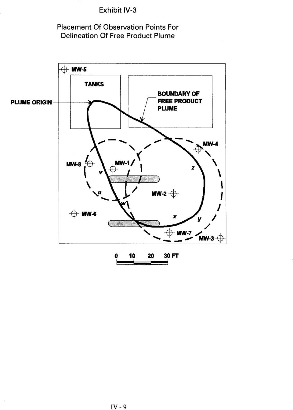
11 well MW-6 is considerably outside the 16 foot radius and the midpoint (point u ) significantly overestimates the plume boundary. For interior observation points, these conditions are reversed. Well MW-2 is an internal observation point, which lies 70 feet from the plume origin. The dashed circle around MW-2 has a radius of 28 feet (40 percent of 70 feet). Note that wells either on this radius (MW-4) or inside (MW-7), result in an underestimation of the plume boundary (points x and z, respectively). The midpoint (point y ) between wells MW-1 and MW-3 (just slightly outside the 28 foot radius) is reasonably close to the actual plume boundary. If the observation point is too far outside the radius, then the extent of the plume will be overestimated. For both interior and perimeter wells, interpolation accuracy is improved if a straight line between the two observation points intersects the plume boundary at a right angle. Significant deviation from 90 results in increasing error in estimation of the plume boundary. As may be expected, there are exceptions to these guidelines. For instance, the midpoint (point w ) between MW-2 and MW-6 is reasonably close to the actual plume boundary despite the fact that a line drawn between the two wells intersects the boundary at an angle significantly different from 90. In spite of the uncertainty in this process, a line beginning at the plume origin drawn so that it connects points v-w-x-y-z and returning to the origin is a reasonable approximation of the actual plume boundary. The approximation could be improved by adding additional observation points to fill in the gaps: Near point w, between MW-3 and MW-4, and between MW-1 and MW-4. Exhibit IV-4 shows alternative observation point spacing for free product plumes of various sizes and shapes. In reviewing a free product recovery plan, the adequacy of the delineation of the free product plume is one of the first technical factors to be checked. If the extent of the plume is not defined in all directions from the source area (plume origin), then more site characterization is required. This deficiency frequently occurs when the free product plume is not defined beyond the site property boundary. Excavations And Test Pits Excavation of tanks or pipelines is commonly performed soon after a hydrocarbon release has been confirmed or suspected. These excavations provide for direct observation of the areal and vertical distribution of hydrocarbons. Such observations, if noted and located on a sketch map, can be used to partially identify the extent of free product. However, where the water table is below the maximum depth of the excavation equipment, the extent of lateral spreading at the water table won t be defined. For those sites where the water table is very shallow (i.e., less than 8 feet), excavation of test pits can be a quick and cost effective approach to delineating IV - 10
 between wells MW-1 and MW-3 (just slightly outside the 28 foot radius) is reasonably close to the actual plume boundary.")
12 Exhibit IV-4 Delineation Of Free Hydrocarbon Plume Extent Using Soil Borings Or Probes And Monitoring Wells IV - 11

13 the extent of free product. Direct observations of the geologic media and potential preferential permeable pathways or barriers can also be obtained from test pits. The practicality of using of test pits diminishes with depth. Entry into test pits greater than 4 feet requires shoring, a trench box, or sloping of the sides of the excavation to protect workers from cave-in. Such measures although necessary, can be expensive and time consuming to construct or install. In some cases observations can be made from the surface without actually entering the excavation, but visual inspection of deep test pits from the surface is more difficult and less reliable than in shallow test pits. Also, excavated materials, if contaminated, will have to be handled appropriately (e.g., treatment/disposal) which can add to the expense of the investigation. Soil Borings The three-dimensional distribution of liquid hydrocarbons can best be determined through a systematic program of soil sampling and free product thickness measurements. These observations may be collected through the use of traditional soil boring and sampling equipment or direct push (DP) technologies. Traditional soil boring techniques include augers (both drill rig-operated hollowstem and solid stem as well as hand augers) and other rotary drilling methods. Core samples collected by auger rigs are typically obtained using split-spoons and shelby tubes. Direct push technologies, which are also known as direct drive and soil probe technologies, also include cone penetrometer (CPT) and relatively simple, mechanically assisted push samplers (e.g., impact hammers, hydraulic presses). DP systems drive, push, and/or vibrate small-diameter steel rods into the ground. These rods may be fitted with specialized tools to collect subsurface samples and data either continuously or over discrete intervals. A wide variety of sampling tools is available for collecting samples of solids (soil), liquids (free product and groundwater) and gas (soil vapor). CPT cones are specially designed to collect continuous lithologic data as the tools are pushed at a constant rate into the subsurface. The presence of free product can be detected using laser induced fluorescence (LIF) technology or other in situ analytical screening methods. DP technologies are generally suitable to depths of up to 100 feet under ideal conditions (i.e., unconsolidated soils free of coarse gravels and cobbles), but at most sites the depth range is between 20 and 60 feet. Deeper penetration typically requires rotary (air or mud) drilling methods. Manual techniques are generally only practical to depths between 0 and 15 feet. None of the DP technologies is applicable for sites overlying bedrock, large cobbles or boulders, or cemented sedimentary rock. Under such circumstances, even augers may not be suitable, in which case rotary drilling/coring techniques may be required. IV - 12

14 Direct push techniques offer the following advantages relative to standard soil boring methods:! Ability to collect samples rapidly and obtain a large number of samples.! Capability to collect samples of soil, liquid, and gas.! Little or no generation of soil cuttings.! Deployment vehicles are more mobile and require less overhead clearance than drill rigs.! Lower cost per sample in most settings. At sites where the use of DP technologies is appropriate, characterization of the subsurface can be more comprehensive than is typically achieved using traditional methods. Where free product recovery (or other remedial alternatives) is required, a more efficient and cost-effective system can be designed for sites that are better characterized. The additional expense of a site characterization conducted using DP technologies can be recovered (possibly many times over) in savings achieved during the remediation phase. However, because the size of the DP borehole is small, installation of free product recovery wells usually must be accomplished with traditional drilling rigs. Monitor Wells Properly installed and constructed monitor wells can be used both to delineate the extent of free product and monitor temporal changes in free product accumulations. However, it is also important to realize that monitor wells are subject to significant limitations in their ability to provide accurate measurements of the thickness of free product in the surrounding soil. Free product can accumulate in a well only if the well is open (i.e., screened) across the zone of free product (Exhibit IV-5a). A well screened above the water table will generally be dry (Exhibit IV-5b). A well screened below the zone of free product will collect water but no free product (Exhibit IV-5c). Within a well with a properly positioned screen, the thickness of free product typically fluctuates in response to changes in water table elevation. With each rise (or fall) in water table elevation, the measured thickness of free product also changes, resulting in a different calculation of actual thickness in the soil (Durnford, et al., 1991). Where a free product recovery plan relies on wells for free product delineation, the reviewer should check the construction diagram of each well and verify that the open (screened) interval of each well straddles the water table. Where wells are initially installed with short screens (i.e., 5 feet or less), changes in the water table IV - 13

15 Exhibit IV-5 Monitoring Well Installations And Their Ability To Detect Free Product Source: API, A Guide to the Assessment and Remediation of Petroleum Releases, 3 rd edition. API Publication 1628, Washington, DC. Reprinted courtesy of the American Petroleum Institute. IV - 14

16 elevation may result in a dry well (declining water table) or in a well that is screened below the zone of free product (rising water table). Even in properly constructed wells, the absence of free product may not necessarily indicate that petroleum hydrocarbons (including free product and residual and trapped fractions) are not present in the soil. Similarly to the observation that water may take days or weeks to enter some monitor wells constructed in clayey soil, free product may not initially appear in monitor wells. Such a condition indicates that the relative permeability with respect to free product is very low, hence the mobility of the free product is also low. This may also result in a lower calculated volume of free product. Monitor wells may be installed by any of several methods. (See Driscol, 1986, and Aller et al., 1989, for detailed descriptions of modern well drilling methods.) For unconsolidated media, hollow-stem augers are used most commonly. The well casing and screen are inserted through the opening in the auger. Depending on the stability of the well bore, the sand pack, sealing, and grout can be placed as the augers are retracted or after the augers have been removed. After the monitor well has been constructed, it should be developed by surging or pumping until water is free of turbidity. The development of new wells in very fine grained materials may not be practical because of its slow recharge rate. For a well with a slow recharge rate, development involves dewatering the well and allowing it to recover for one or more cycles. The development of the monitor well will tend to pull in free product and overcome capillary barriers as a result of the smearing of fine-grained material on the well bore. Without adequate development, free product may accumulate very slowly in the monitor wells (over a period of months). In these cases, initial estimates of the extent of free product may be understated. Product may also enter slowly, or not at all, if the wrong sized sand (filter) pack has been installed. The sand (filter) pack must be four to six times coarser than the aquifer material (Hampton and Heuvelhorst, 1990). The rate of product entry and recovery in wells can be improved by using hydrophobic filter packs (Hampton, 1993). The presence of free product at a well is indicated by the accumulation of a measurable thickness of hydrocarbons in it. Three following methods (see Exhibit IV-6) are commonly used to measure free product thickness in a well:! Steel tape and paste! Interface probe, and! Bailer. The pastes used with the steel tape are sensitive to hydrocarbons and water. Commercially available interface probes sense the presence of both oil and water. The first two methods are accurate to within about 0.01 foot and are IV - 15

17 Exhibit IV-6 Methods For Measuring Accumulations Of Free Liquid Hydrocarbons In A Well Source: API, A Guide to the Assessment and Remediation of Petroleum Releases, 3 rd edition. API Publication 1628, Washington, DC. Reprinted courtesy of the American Petroleum Institute. IV - 16

18 convenient for determining the elevation of the air/free product and oil/water interfaces. Whenever possible measurements should be taken using either steel tape and paste or an interface probe. A bailer is a transparent cylinder with a check valve at its base. The bailer method can significantly under- or overestimate the thickness of free product in the well and should not be used for determining the elevations of air/free product and free product/water interfaces. Disposable bailers, which are commonly dedicated to monitoring wells containing free product, typically collect an unrealistically small product thickness because of the small size of the intake holes. The use of bailers should be limited to verification of the presence of free product in a well or collection of a sample of it. Bailers can be used to remove liquids from monitoring wells during bail-down tests that are designed to determine the rate of free product recovery into wells. Volume Estimation Knowledge of the volume of hydrocarbons in the subsurface is useful for evaluating the performance of a free product recovery system in terms of both total volume recovered and time required for recovery. In some instances the original release volume may be unknown but can be estimated by calculating the volume of free product present in the subsurface. Several methods can be used to estimate hydrocarbon volumes. These include:! Compilation of historical information on release events and from inventory records.! Soil sampling and analysis for total petroleum hydrocarbons.! Correlation of the thickness of free product measured in monitoring wells to total volume of free product.! Evaluation and projection (extrapolation) of free product recovery data. The first two approaches yield estimates of total hydrocarbons--residual and free--present in the subsurface. The last two methods--product thickness measured in monitor wells and recovery data--provide estimates of the volume of free product. None of these four methods are entirely precise in most settings because of limited and uncertain data. Even where substantial data are available and several estimation methods used, volume estimates with an uncertainty of minus 50 percent to plus 100 percent are the best that can be expected. IV - 17

19 Exhibit IV-7 presents a brief summary of the salient points of each of these four methods. The relative mass present as free and residual liquid hydrocarbons is large compared to the mass of dissolved or vapor phase hydrocarbons in most subsurface settings. Residual hydrocarbons may represent as much as 50 to 80 percent of the total volume that was originally released. Recoverable free product typically represents 20 to 50 percent of the total. The ratio of free product to residual liquid hydrocarbons tends to decrease with time as plume migration and other processes occur that trap free hydrocarbons (e.g., rising or falling water table). The relative permeability (and mobility) of the free product decreases as more of the free product is recovered and the level of liquid hydrocarbon saturation decreases. When the saturation approaches the residual saturation of the geologic medium, free product will stop flowing readily into monitor/recovery wells. At this point, the recovery well or recovery system should be switched to operate intermittently or possibly turned off altogether. Small quantities of liquid hydrocarbons may continue to slowly drain into wells, but the rates of drainage are usually not sufficient to justify continuous operation of the recovery system. Volume Estimates Based On Release History Historical records of release events and hydrocarbon inventories can be used to estimate the total amount of hydrocarbons lost. When accurate inventory or release data are available, the amount lost is likely to be greater than the amount in the subsurface as a result of volatilization and biodegradation. The reliability of historical data ranges widely, but generally, the older the information, the less reliable it is. Furthermore, historical data generally cannot be used to characterize phase distribution in the subsurface. Even though volume estimates based on release and inventory data may have limited reliability, these estimates are useful in at least two important ways. First, the volume estimate based on historical data can be compared with volume estimates obtained with other approaches to provide a check on the other methods. Second, historical information on when releases began can provide a basis for initial estimates of the extent of free product migration that can be used to assist in locating sampling points and wells for site characterization. IV - 18
.")
20 Exhibit IV-7 Methods For Volume Estimation Method Approach & Results Advantages Disadvantages Release History Review inventory records to determine volume(s) and date(s) of release(s). Relatively simple and statistically accurate if accurate historical data are available. Data rarely accurate given numerous potential error sources (e.g., measurement technique, volume changes due to temperature) TPH Concentration in Soil Samples 1 Convert TPH concentrations in soil samples to saturations and integrate these values over the area of contamination. Data are relatively easy to collect; several methods are available for data integration. Calculations required are relatively complicated; requires a lot of data to reduce uncertainty associated with calculated volume; results may differ among various methods for data integration; TPH analysis may not be representative of actual petroleum hydrocarbon saturations. IV - 19 Product Thickness in Wells Measure the thickness of the accumulated layer of free product in all monitoring wells. Free product thickness measurements in monitor wells are routinely collected on a regular basis; the thickness of the free product layer in the monitor well can be measured quite accurately; several methods are available for data analysis. Product thickness in wells usually exaggerates the thickness in the aquifer--this effect is more pronounced in finer-grained geologic materials; none of the methods that correlate product thicknesses measured in wells to actual product thickness in the soil are reliable either in the field or in the laboratory. Extrapolation of Recovery Data Sum the cumulative product recovery volume and an estimate of the residual volume. Recovery data are routinely collected. Works best during later stages of recovery; many factors can bias recovery (e.g., smearing); requires two types of data. 1 The U.S. Air Force is currently working on an alternative method of using TPH values based on examination of TPH fractions. EPA will release information on this process after peer review has been completed.
 TPH Concentration in Soil Samples 1 Convert TPH concentrations in soil samples to saturations and integrate these values over the area of")
21 Volume Estimates Based On Soil Samples Estimation of the volume of free product in the subsurface based on soil sample data first requires the collection of soil samples and their subsequent analysis for hydrocarbon content. Hydrocarbon content in soil samples can be measured by a variety of standard laboratory methods. These methods include solvent extraction, solvent extraction with distillation, and centrifuging (Cohen and Mercer, 1993; Cohen et al., 1992). The total petroleum hydrocarbons (TPH) analysis commonly used in site assessments is based on solvent extraction. For sites where sufficient TPH data are available, volumes of hydrocarbons in the unsaturated and saturated zones can be estimated. One limitation of TPH data is that it does not distinguish between individual petroleum hydrocarbons or between petroleum hydrocarbons and other non-petroleum organic matter that may be present in the soil sample. The estimation of hydrocarbon volumes based on soil sample data is subject to significant uncertainty because of the sparseness of the data and the often extreme variability in hydrocarbon concentration within the soil. Exhibit IV-8 shows how variable hydrocarbon saturation can be within the same boring and between three different borings at a typical site. The detail shown in Exhibit IV-8 is much greater than that obtained during most site characterization investigations, but even with this amount of detail at one or more boring, there is still tremendous uncertainty about concentrations in the soil between the borings. The procedure for estimating liquid hydrocarbon volumes from TPH data involves two calculation steps: (Step 1) TPH results are converted to saturation values at each point, and (Step 2) the volume of liquid hydrocarbons is determined by integrating point saturation data over the volume of subsurface where hydrocarbons are present. The conversion calculation (Step 1) is straightforward and is illustrated in Exhibit IV-9. Integration of the total hydrocarbon volume (Step 2) can be accomplished using standard interpolation and integration techniques. As a simple example, TPH (saturation) results are plotted at their collection locations on a site map. Contours of equal saturation are drawn on the map. The area and volume represented by each contour level is then calculated. Integration is merely the summation of the individual volumes. There are a number of more sophisticated techniques, including computer software, but discussion of these is beyond the scope of this manual. It is also important to recognize that interpolation and integration methods yield only approximations of what is actually present in the field and different methods using the same data set can result in volume estimates that range from minus 30 percent to plus 50 percent. In general, as the number of data points increases the error associated with the method decreases. IV - 20
22 Exhibit IV-8 Measured Hydrocarbon Saturation Profiles At Three Boreholes Showing Variability Due To Vertical Heterogeneity IV - 21
23 Exhibit IV-9 Calculation Procedure To Convert TPH Data From Soil Samples To Hydrocarbon Saturations TPH analysis results for soil samples may be converted to hydrocarbon saturation by the following equation: S o = TPH ( 1 φ) ρ 10 6 gr φ ρ o kg mg where: S o = total hydrocarbon saturation (dimensionless) TPH = total petroleum hydrocarbon concentration in mg/kg ρ gr φ ρ o = grain density (typically 2.65 g/cm 3 ) = porosity (dimensionless) = density of the hydrocarbon, liquid (g/cm 3 ). This equation applies to both the unsaturated and saturated zones. The amount of free hydrocarbon present can be calculated if residual hydrocarbon saturation is known or estimated. Usually residual saturations are not known or measured, but literature values (e.g., Mercer and Cohen, 1990) can be used as estimates. The free hydrocarbon saturation is given by: where: S of S r Sof = So Sr = free hydrocarbon saturation = residual hydrocarbon saturation. IV - 22
24 Volume Estimates Based On Product Thickness In Wells The limitations of monitor wells in providing representative measurements of free product thickness in the adjacent soil are well documented. Fluctuations in the water table can result in large differences in measured hydrocarbon thickness even though the in situ volumes are not significantly changed. Increases in hydrocarbon thickness are commonly observed with declining water tables. API (1989) attributes the thickness increase to drainage from the unsaturated zone. As the water table falls, hydrocarbons previously trapped as a residual phase can become remobilized and enter into wells. Kemblowski and Chiang (1990) relate the changes to preferential fluid flow through the well (Exhibit IV-10). Many investigators have tried to develop methods to explain how small amounts of mobile hydrocarbons can lead to exaggerated thicknesses of hydrocarbons measured in wells. Hampton and Miller (1988) and Ballestero et al., (1994) provide comprehensive reviews of the methods used to estimate the thickness of free product in the adjacent soil from measurement in monitor wells. A comparison of the predictability of these alternative methods indicates an order of magnitude accuracy of the predicted versus the measured free product thickness among the methods. These investigations can be grouped into two primary approaches: (1) Derivation of empirically-based correlations--typically based on fluid density differences, grainsize of the geologic media, or height of the water capillary fringe, and (2) development of models based on idealized capillary pressure-saturation curves. In spite of the intense attention that has been focused on developing a correlation between free product thickness measured in wells and volume of free product in the soil, none of the available methods has been particularly reliable when tested either in the field (Durnford et al., 1991; Huntley et al., 1992; and Ballestero et al., 1994) or even in the laboratory (Hampton and Miller, 1988). Durnford et al., (1991) summarize the limitations of the methods developed to relate the free product thickness measured in monitor wells to the volume of free product in the soil as follows:! Free product thicknesses observed in monitoring wells change over time as the water table fluctuates. Each different measured thickness of free product results in a different calculation of free product in the aquifer, even if the actual volume of free product (including residual and trapped) hasn t changed. IV - 23
25 Exhibit IV-10 Effects Of Falling Or Rising Water Table On Hydrocarbon Thicknesses Measured In Wells IV - 24
26 ! None of the estimation methods accounts for residual and trapped petroleum hydrocarbons--a portion of these fractions can be returned to the free product fraction as the water table moves up or down.! Methods that are based on measurement of soil and fluid properties require measurements (e.g., curves of capillary pressure vs water saturation) that are difficult to obtain in the field, and laboratoryderived measurements may not accurately represent field conditions.! None of the methods account for spatial variability (heterogeneity) of aquifer parameters. The movement of free product is strongly dependent upon aquifer heterogeneities, which are rarely represented adequately by average properties. Despite the drawbacks with these volume estimation methods, they are frequently used in practice. To illustrate how some of these methods are used, we present a comparison of seven methods reported in Ballestero et al., (1994). The seven different approaches can be grouped into the following four categories:! Correlation based on the density of the liquid hydrocarbon (de Pastrovich et al., 1979);! Correlation based on properties of the geologic medium (Hall, et al., 1984);! Correlation based on the height of the water capillary fringe (Blake and Hall, 1984; Ballestero et al., 1994; and Schiegg, 1985); and! Models based on idealized capillary pressure relationships for homogeneous porous media (Farr et al., 1990; and Lenhard and Parker, 1990). Exhibit IV-11 summarizes the results of calculations for each of the different methods listed above using data from laboratory experiments reported by Abdul et al., (1989), with additional parameter values acquired (where IV - 25
27 Exhibit IV-11 Comparison Of Seven Alternative Methods For Correlation Of Product Thickness Measured In A Monitor Well To Actual Thickness In The Soil Calculated Results (Hydrocarbon Thickness in Soil) Measured hydrocarbon thickness in the soil (cm) de Pastrovich et al. (1979) Hall et al. (1988) Blake and Hall (1984) Ballestero et al. (1994) Schiegg (1985) Farr et al. (1990) Lenhard and Parker (1990) IV Note: All values in centimeters except those for Farr et al. (1990) which are volume in cm 3 /cm 2. This comparison is based on a study published by Ballestero et al. (1994) using data published in Abdul et al. (1989). Additional data required for the methods of Lenhard and Parker (1990) and Farr et al. (1990) were obtained from their respective papers. Note that the results presented above are only applicable for the data specified in this example. The use of different data may alter the relative performance of the methods. Refer to the Appendix for a more complete presentation of the individual equations used in this comparison.
28 necessary) from the individual papers. A more complete presentation (including the equations, variable descriptions, input data and discussion of the salient features) is included in the Appendix. It is important to realize that the relative performance of these methods is dependent upon the specific experimental conditions. Given another set of data obtained from a different experiment using different soil (with different grainsize, porosity, and residual saturation) and different liquid hydrocarbon, the relative performance may be radically different. To reiterate from the opening paragraph in this section, none of the available methods has been particularly reliable when tested in either the field or the laboratory. For any given site, it is probably not likely that the method that will ultimately yield the closest match to conditions in the field can be chosen a priori. However this is not to say that there is no point in using these methods to estimate free product volumes. On the contrary, free product thickness data collected from monitor wells is typically plentiful, easily collected, and is usually accurate. In many instances these data may be all that are available. What is most important is to not rely too heavily on one method over another. The best approach is to use more than one method so that a probable range of volumes can be calculated. Volume Estimates Based On Extrapolation Of Free Product Recovery Data The difference between the volume of free product released and the volume recovered equals the volume remaining in the subsurface. Often the volume of the release is not known, but in theory it can be determined if the volume of free product that has been (or is anticipated to be) recovered and the volume remaining (or is anticipated to remain) in the subsurface is known. Knowledge of any of these three volumes is associated with a degree of uncertainty, and it is usually not possible to quantify the error associated with estimates of these volumes. Many factors contribute to this uncertainty. Some of the components of the types of petroleum hydrocarbons typically stored in USTs are volatile and/or soluble, and are therefore not likely to be measured as residual hydrocarbons. Biodegradation may further decrease the amount of hydrocarbons present in the subsurface. As was discussed previously, hydrocarbon saturations in soil borings are highly variable in both the vertical and horizontal directions. Samples with anomalously high or low saturations can bias estimates of total residual hydrocarbons remaining in the subsurface. Also, it is important to recognize that the rate of free product recovery typically exhibits a logarithmic decrease with time. The rate of decrease can be quite variable even on the same site due to heterogeneities in the soil which influence residual saturation and relative permeability. The estimate of product remaining in the subsurface as either free or residual changes constantly with time as recovery progresses. Despite these limitations, this method may offer the best (or only) means for estimating volumes at a particular site. Although this method works best late in the recovery phase (after the cumulative recovery curve levels off), it can be used IV - 27
29 at any time with the understanding that volume estimates based on early recovery data will be associated with a higher degree of uncertainty. Methods to estimate free product recovery rates are presented in the following sections. Estimation Of Recovery Rates An important design consideration for free product recovery is the rate at which liquid hydrocarbons can be collected by pumping or skimming techniques. The rate of recovery will depend on the design of the recovery system, the type(s) and distribution of free product in the subsurface, and the hydrogeological conditions. Expected recovery rates are used to size the free product storage tanks and oil/water separators, and, to a lesser degree, to select and size recovery equipment and treatment equipment. Not only is it important to estimate the initial recovery rates but also to predict how the recovery rates will change with time after recovery starts. Estimates of recovery rates can be obtained from field tests (e.g., bail down tests, pumping tests) or from multiphase flow analysis. Usually, recovery rates of free product decline after startup because wells and trenches are located in areas where the volumes of free product are highest. In some settings where wells or trenches pull free product from some distance, recovery rates may increase for a significant duration before declining. Bail Down Test And Pumping Tests A bail down test involves removing the free product from a well by bailing and measuring the thickness of and depth to free product in the well as it recovers. These tests have been used to estimate free product thickness by some investigators (Hughes et al., 1988; Wagner et al., 1989; and Gruszczenski, 1987) with limited success. These tests can easily provide estimates of initial recovery rates for a skimming type operation (see Exhibit IV-12, Method 1). In order for the results of a bail down test to be applicable, the free product recharge rate should be slow relative to the rate of groundwater recharge. Where free product recharges the well in less than a few minutes, it is difficult to accurately monitor recovery rates (Hampton, 1993). For systems where free product will be collected by active pumping of groundwater and product, a pumping test can be used to estimate initial free product recovery rates (see Exhibit IV-12, Method 2). Pumping tests (or aquifer tests) are usually performed to determine groundwater flow properties such as hydraulic conductivity and transmissivity. Estimates of free product recovery rates can be obtained by collecting additional data in conjunction with a standard (groundwater) pumping test or by conducting a specialized pumping test or pilot test. IV - 28
30 Exhibit IV-12 Sample Calculations For Estimating Initial Free Product Recovery Rates Method 1. Bail down testing (Applicable to skimming-type recovery systems). Field Data Inside Diameter of Well Screen = 4 inches Radius = 2 inches = foot 1. Maximum thickness from table. = 1.15 feet 2. 80% x maximum thickness recovery. (0.8 x 1.15) = 0.92 foot 3 Time corresponding to 80% of recovery interpolated from table. 3 hours 24 min = 204 min 4. Compute gallons per foot of oil thickness in well screen. π x (well radius in ft) 2 x (conversion factor ingal/ft 3 ) = gal/ft x (0.166) 2 ft 2 x 7.48 gal/ft 3 = 0.65 gal/ft π 5. Compute average recovery rate to 80% recovery gal/ft x 0.92 ft/204 min = gal/min = 4.2 gal/day Recovery Free Product Time Thickness (ft) 2 min min min min hour hours hours hours hours hours 1.10 Method 2. Constant rate pump test (Applicable to free product recovery with water level depression). Pumping Rate = 10 gal/min 1. Compute average hydrocarbon recovery rate from table for 24 hours. 2. Compute 52.1 gal/24 hours = 2.17 gal/hour = gal/min Field Data Time Since Cumulative Pumping Hydrocarbons Started Collected 10 min 0.0 gal 20 min 0.3 gal 40 min 0.8 gal 1 hour 2.5 gal 2 hours 5.8 gal 4 hours 14.6 gal 8 hours 23.8 gal 24 hours 52.1 gal Hydrocarbon Recovery Rate Hydrocarbon Recovery Ratio = Total Pumping Rate gal/min = = 0.361% 10 gal/min IV - 29
31 A standard pumping test involves pumping groundwater at a constant rate and monitoring changes in groundwater elevations in the pumping and nearby wells during the test. If free product is present in the vicinity of the well, the pumped fluid will contain both free product and groundwater. The ratio of free product recovered to total fluid recovered can be determined at different times during the test by collecting samples of pumped fluid. These samples may show considerable variability, so as many samples as practicable should be collected during the test. Where the ratios of recovered product to total fluid are more than a few percent, simple volume measurements of the separated liquids may be used to determine the recovery ratio (see Exhibit IV-13). Usually the recovery ratio of free product to total fluid is less than a few percent, in which case the ratio may be determined by a standard TPH or oil and grease analytical method. Estimates of free product recovery rates can also be obtained from pilot tests or records of free product pumping that may have been performed as an interim or emergency removal action. Information from pilot tests or prior free product recovery systems provide the best estimates of expected free product recovery rates because the duration and rates of pumping are usually much greater than those of bail down or pump tests. Multiphase Flow Analysis The theory of multiphase flow in porous media has been widely used in petroleum reservoir engineering for over 50 years. During the past decade, these same theories have been applied to analysis for environmental applications. Because multiphase flow theory results in complex non-linear partial differential equations, few simple solutions to practical problems are available. One such solution is presented in the preceding section (see Exhibit IV-13). Commonly, the governing equations are solved by a variety of sophisticated numerical techniques using computer models. IV - 30
32 Exhibit IV-13 Computational Procedure For Determining Ratio Of Free Product Recovery To Total Fluid Recovered From A Single Recovery Well Basic Equations: Mobility of Water = k k rw µ ρ w w g Transmissivity of Water, T w = b k ρ w µ w w g Mobility of Free Product = k k ro µ ρ o o g where: k is the intrinsic permeability (L 2 ) k rw is the relative permeability of water (dimensionless) k ro is the relative permeability of free product (dimensionless) k ro ρ w is the average relative permeability of free product layer (dimensionless) is the density of water (ML -3 ) Transmissivity of Free Product, T o = is the density of free product (ML -3 ) ρ o g is the gravitational constant (LT -2 ) µ w is the viscosity of water (ML -1 T -1 ) b k k o ro o µ is the viscosity of free product (ML -1 T -1 o ) b o is the thickness of free product layer (L) b w is the thickness of aquifer below free product layer (L) Assumed: Water transmissivity of free product layer is negligible µ o ρ g IV - 31
33 Exhibit IV-13 (continued) Computational Procedure For Determining Ratio Of Free Product Recovery To Total Fluid Recovered From A Single Recovery Well Ratio General Equation: ( Free Product Recovery Rate Total Fluid Recovery Rate ) = Qo Q + Q o w = T o T o + T w where: Assumed: = b k b k ρ / µ o ro o o ρ / µ + b ρ / µ o ro o o w w o Q is volumetric flowrate of free product (o) or groundwater (w) Same hydraulic gradients exist in free product layer and groundwater EXAMPLE: A 2-foot-thick hydrocarbon layer has an average hydrocarbon saturation of 0.5, a viscosity of 4 centipoise, a density of 0.9 g/cm 3. The average relative permeability for a free product saturation of 0.5 is assumed to be The pumping well is screened across the hydrocarbon layer to the base of the aquifer which has a saturated thickness of 20 feet including the hydrocarbon layer. Q o Q + o Q w = T o T + o T w = 2 ft g / ml / 4cp 2 ft g / ml / 4cp + 18 ft 1g / ml / 1cp = = For a total fluid production rate (Q o + Q w ) of 2 gallons per minute, determining free product recovery rate, Q o. Q o = Ratio x (Q o + Q w ) = x 2 gpm = gpm IV - 32
34 Calculations Of Initial Free Product To Total Fluid Recovery Ratio. A straightforward calculation based on the relative mobility of free product and water can be used to determine the ratio of free product to total fluid production under pumping conditions in a single well. This procedure is described and illustrated in Exhibit IV-13, which shows that for thin hydrocarbon layers and moderately high viscosities, the recovery of free product will be a small portion of the total fluid production in the well. Use Of Computer Models. In theory, computer models based on multiphase flow concepts can be used to predict free product recovery rates. Selection of a model for a particular site must be made carefully because all models are not appropriate for all sites. Factors to be considered include; complexity of site geology, availability of input data, and special features of the site (e.g., pumping wells, fluctuating water table). Some of the numerous multiphase flow models that have been developed include:! Simplified models simulating downward migration of liquid hydrocarbons through the unsaturated zone, radial transport of a hydrocarbon lens in the watertable, and radial migration of hydrocarbons to a recovery well (El-Kadi, 1992; El-Kadi, 1994; Weaver et al., 1994; and Charbeneau and Chiang, 1995).! Complex numerical models (finite-difference and finite-element) of immiscible multiphase flow in porous media in cross-section or three-dimensional (Faust et al, 1989; Kaluarachchi and Parker, 1989; Katyal et al., 1991).! Complex numerical models of areal hydrocarbon migration in unconfined aquifers simplified from 3-D to 2-D (Kaluarachchi et al., 1990). Despite the seemingly wide variety of models that are available, in practice the usability of models for reliable prediction of free product recovery rates is limited for a variety of reasons. Many of the models require data that are not measurable in the field (e.g., relative permeabilitycapillary pressure relations). Mishra et al. (1989) present one solution to this problem; they developed a model to estimate relative permeability-capillary pressure relations from grain-size curves, which can be developed relatively easily from soil samples. The problem is that each soil sample would yield a different grain-size curve, and hence, different relative permeabilitycapillary pressure curves. As even subtle heterogeneities can radically influence the movement of free product in the subsurface, no single curve is likely to be adequate to characterize the entire site. Collection of a sufficiently large number of samples may be prohibitive. Assumptions such as vertical equilibrium and vertical uniformity, which are usually required by the simpler two-dimensional models, are not generally applicable. More often than not model simulations are very accurate only over the period for which field data are available. Models are calibrated given a set of field data (e.g., water table elevations, volume of product recovered) collected over a specified period of time. Model parameters are then adjusted so that the simulated results as closely as possible match the field IV - 33
35 data. As more field data are collected, model parameters are adjusted so that the simulation results once again closely match the field data. This process is typically repeated every time additional data are available. Often the final set of model parameters is quite dissimilar from the initial set. If the initial parameters are used over the entire simulation period, then the match is usually best during the early stages and worsens as the simulation progresses. Conversely, if the final parameters are used to simulate the behavior measured in the field, the match is typically poor during the initial stages, but improves as simulation time progresses up to the point in time that the latest data are available. It is reasonable to expect that the simulation results would begin to worsen as the simulation continued to progress into the future. Appropriate use of models generally requires that they be used by persons experienced in the use of models. As the complexity of the site and the selected model both increase, so must the sophisitication of both the modeler and the computer. Adequately trained modelers command relatively high hourly billing rates. A single simulation using a complex, multi-phase model may take 24 hours or more to run even on today s fastest desk top computers. Often clients are billed for computer time as part of the overall cost for computer modeling. Between the labor rates and the computer usage rates, several simulations of even a small site can result in a large invoice. Because of limited reliability and expense of use, multiphase computer models are seldom used to estimate recovery rates for a free product recovery plan. For sites with large spills or large volumes of free product in the subsurface, the expense and effort associated with these models may be warranted if it can help significantly reduce the cost of recovery or improve the effectiveness of free product recovery. Where models have been used to design free product recovery systems, the analysis is likely to contain significant uncertainty that should be explicitly addressed in the model description. Recoverability Of Free Product Chapter IV has presented several methods for evaluating the volume and recoverability of free product. This section presents a discussion limited to those factors that are most relevant to the recovery of the principal types of petroleum products typically stored in USTs (i.e., gasolines, middle distillates, and heavy fuel oils). It has been established that the thickness of free product measured in wells usually exceeds the thickness that is present in the surrounding soil. Volume estimates based strictly on measured thickness in wells are erroneous and are often significantly greater than the volume of product that was released. Many methods have been developed to correlate the measured thickness to volume in the soil, but none of the available methods is reliable at all sites. Different methods applied to the same site may yield radically different volume estimates. It is, therefore, important not to rely on the estimate of any single method. Comparison of several estimates may provide a reasonable range for the estimated volume. This range may span an order of magnitude. IV - 34
36 The steps involved in estimating the volume of free product in the subsurface include measurements of thicknesses in wells, borings, and excavations; determination of the direction(s) of groundwater flow and free product migration; and estimation of the retention capacity of the soil. Once the probable extent and realistic thicknesses of the free product plume (or pool) have been determined, a variety of techniques are available to calculate the total volume of the release. Under the most favorable conditions, only a fraction of the total release will be recoverable. Recoverable volumes typically range from 20 to 50 percent of the total release. Factors that influence the recoverable percentage include water table fluctuations (which can create a smear zone ), depth to water table, and soil properties (e.g., heterogeneity, pore size, layering). The initial rates of product recovery are best estimated from bail down tests and pumping tests. Knowledge of the expected recovery rates are important in sizing components of the treatment process. Often the recovery of product declines significantly from initial rates, especially for wells located where free product volume is highest. Various computer models can, in theory, be used to predict future rates of free product recovery. However, these models are expensive to use and have limited reliability. IV - 35
37 Primary References Abdul, A.S., S.F. Kia, and T.L. Gibson, Limitations of monitoring wells for the detection and quantification of petroleum products in soils and aquifers, Ground Water Monitoring Review, 9(2): API, A Guide to the Assessment and Remediation of Underground Petroleum Releases, Third Edition, API Publication 1628, Washington, D.C. Ballestero, T.P., F.R. Fiedler and N.E. Kinner, An investigation of the relationship between actual and apparent gasoline thickness in a uniform sand aquifer, Ground Water, 32(5): Blake, S.B. and R.A. Hall, Monitoring petroleum spills with wells: some problems and solutions, Proceedings, Fourth National Symposium on Aquifer Restoration and Groundwater Monitoring, National Water Well Association, Columbus, OH, pp de Pastrovich, T.L., Y. Baradat, R. Barthel, A. Chiarelli, and D.R. Fussell, Protection of ground water from oil pollution, CONCAWE, The Hague, Netherlands. Durnford, D., J. Brookman, J. Billica, and J. Milligan, LNAPL distribution in a cohesionless soil: a field investigation and cryogenic sampler, Ground Water Monitoring Review, 11(3): EPA, Subsurface Characterization and Monitoring Techniques, Volume 1, Solids and Groundwater, EPA/625/R-93/003a. Farr, A..M., R.J. Houghtalen, and D.B. McWhorter, Volume estimation of light nonaquous phase liquids in porous media, Ground Water, 28(1): Hall, R.A., S.B. Blake, and S.C. Champlin, Jr., Determination of hydrocarbon thickness in sediments using borehole data, Proceedings, Fourth National Symposium on Aquifer Restoration and Groundwater Monitoring, National Water Well Association, Columbus, OH, pp Hampton, D.R. and P.D.G. Miller, Laboratory investigation of the relationship between actual and apparent product thickness in sands, Proceedings Conference on Petroleum Hydrocarbons and Organic Chemicals in Ground Water - Prevention, Detection, and Restoration, National Ground Water Association, Dublin, OH, pp IV - 36
38 Kemblowski, M.W. and C.Y. Chiang, Hydrocarbon thickness fluctuations in monitoring wells, Ground Water, 28(2): Lenhard, R.J. and J.C. Parker, Estimation of free hydrocarbon volume from fluid levels in monitoring wells, Ground Water, 28(1): Schiegg, H.O., Considerations on water, oil, and air in porous media, Water Science and Technology, 17: IV - 37
CIVL451. Soil Exploration and Characterization
 CIVL451 Soil Exploration and Characterization 1 Definition The process of determining the layers of natural soil deposits that will underlie a proposed structure and their physical properties is generally
Eurocode 7 - Geotechnical design - Part 2 Ground investigation and testing
 Brussels, 18-20 February 2008 Dissemination of information workshop 1 Eurocode 7 - Geotechnical design - Part 2 Ground investigation and testing Dr.-Ing. Bernd Schuppener, Federal Waterways Engineering
Well gauging results LNAPL in Benzol Processing Area
 Well gauging results LNAPL in Benzol Processing Area 3.59 ft 0.62 ft 4.64 ft Context Scope & Methods Onshore Results Offshore Results Summary & Conclusions 13 Page 1 of 4 Underground Storage Tanks Last
U. S. Army Corps of Engineers Ground Water Extraction System Subsurface Performance Checklist
 U. S. Army Corps of Engineers Ground Water Extraction System Subsurface Performance Checklist Installation Name Site Name / I.D. Evaluation Team Site Visit Date This checklist is meant to aid in evaluating
CONSTANT HEAD AND FALLING HEAD PERMEABILITY TEST
 CONSTANT HEAD AND FALLING HEAD PERMEABILITY TEST 1 Permeability is a measure of the ease in which water can flow through a soil volume. It is one of the most important geotechnical parameters. However,
INSITU TESTS! Shear Vanes! Shear Vanes! Shear Vane Test! Sensitive Soils! Insitu testing is used for two reasons:!
 In-situ Testing! Insitu Testing! Insitu testing is used for two reasons:! To allow the determination of shear strength or penetration resistance or permeability of soils that would be difficult or impossible
How To Prepare A Geotechnical Study For A Trunk Sewer Project In Lincoln, Nebraska
 APPENDIX B Geotechnical Engineering Report GEOTECHNICAL ENGINEERING REPORT Preliminary Geotechnical Study Upper Southeast Salt Creek Sanitary Trunk Sewer Lincoln Wastewater System Lincoln, Nebraska PREPARED
Matt Harris, Golder Associates (NZ) Ltd. The value of geophysics as a non-intrusive method for site characterisation
 Ltd. The value of geophysics as a non-intrusive method for site characterisation") Matt Harris, Golder Associates (NZ) Ltd. The value of geophysics as a non-intrusive method for site characterisation Presentation Outline What is geophysics and how can it help me? Electrical Resistivity
Matt Harris, Golder Associates (NZ) Ltd. The value of geophysics as a non-intrusive method for site characterisation Presentation Outline What is geophysics and how can it help me? Electrical Resistivity
Watershed Works Manual
 National Rural Employment Guarantee Act Watershed Works Manual DRAINAGE LINE TREATMENT: GABION STRUCTURE Baba Amte Centre for People s Empowerment Samaj Pragati Sahayog September 2006 Drainage Line Treatment:
STATE OF VERMONT AGENCY OF NATURAL RESOURCES DEPARTMENT OF ENVIRONMENTAL CONSERVATION WASTE MANAGEMENT DIVISION SOLID WASTE MANAGEMENT PROGRAM
 STATE OF VERMONT AGENCY OF NATURAL RESOURCES DEPARTMENT OF ENVIRONMENTAL CONSERVATION WASTE MANAGEMENT DIVISION SOLID WASTE MANAGEMENT PROGRAM Solid Waste Management Program Waste Management Division 103
Inventory of Performance Monitoring Tools for Subsurface Monitoring of Radionuclide Contamination
 Inventory of Performance Monitoring Tools for Subsurface Monitoring of Radionuclide Contamination H. Keith Moo-Young, Professor, Villanova University Ronald Wilhelm, Senior Scientist, U.S. EPA, Office
A study on the Effect of Distorted Sampler Shoe on Standard Penetration Test Result in Cohesionless soil
 ISSN: 319-53 (An ISO 39: 00 Certified Organization) A study on the Effect of Distorted Sampler Shoe on Standard Penetration Test Result in Cohesionless soil Utpal Kumar Das Associate Professor, Department
c. Borehole Shear Test (BST): BST is performed according to the instructions published by Handy Geotechnical Instruments, Inc.
: BST is performed according to the instructions published by Handy Geotechnical Instruments, Inc.") Design Manual Chapter 6 - Geotechnical 6B - Subsurface Exploration Program 6B-2 Testing A. General Information Several testing methods can be used to measure soil engineering properties. The advantages,
Design Manual Chapter 6 - Geotechnical 6B - Subsurface Exploration Program 6B-2 Testing A. General Information Several testing methods can be used to measure soil engineering properties. The advantages,
1 Mobilisation and demobilisation 1 Deep boring sum 2 Cone penetration tests sum 3 Miscellenous tests sum
 Malaysian Civil Engineering Standard Method of Measurement (MyCESMM) CLASS D: SITE INVESTIGATION WORK Measurement covered under other classes: Excavation not carried out for the purpose of soil investigation
APPENDIX N. Data Validation Using Data Descriptors
 APPENDIX N Data Validation Using Data Descriptors Data validation is often defined by six data descriptors: 1) reports to decision maker 2) documentation 3) data sources 4) analytical method and detection
Frequently Asked Questions on the Alberta Tier 1 and Tier 2 Soil and Groundwater Remediation Guidelines. February 2008
 Frequently Asked Questions on the Alberta Tier 1 and Tier 2 Soil and Groundwater Remediation Guidelines February 2008 Frequently Asked Questions on the Alberta Tier 1 and Tier 2 Soil and Groundwater Remediation
Site Investigation. Some unsung heroes of Civil Engineering. buried right under your feet. 4. Need good knowledge of the soil conditions
 This is an attempt to create a stand alone self learning module on site investigation. Fasten your seat belts. Sit back, relax and enjoy. 1 2 Site Investigation Some unsung heroes of Civil Engineering
COST AND PERFORMANCE REPORT
 COST AND PERFORMANCE REPORT Pump and Treat of Contaminated Groundwater at the United Chrome Superfund Site Corvallis, Oregon September 1998 Prepared by: SITE INFORMATION Identifying Information: United
EXPERIMENT 10 CONSTANT HEAD METHOD
 EXPERIMENT 10 PERMEABILITY (HYDRAULIC CONDUCTIVITY) TEST CONSTANT HEAD METHOD 106 Purpose: The purpose of this test is to determine the permeability (hydraulic conductivity) of a sandy soil by the constant
Site Assessment for the Proposed Coke Point Dredged Material Containment Facility at Sparrows Point
 Site Assessment for the Proposed Coke Point Dredged Material Containment Facility at Sparrows Point Prepared for Maryland Port Administration 2310 Broening Highway Baltimore, MD 21224 (410) 631-1022 Maryland
Oil and Gas Exploration and Production Oil and gas exploration and production... 22a-472-1
 Department of Environmental Protection Sec. 22a-472 page 1 (4-97) TABLE OF CONTENTS Oil and Gas Exploration and Production Oil and gas exploration and production... 22a-472-1 Department of Environmental
Risk Management Procedure For The Derivation and Use Of Soil Exposure Point Concentrations For Unrestricted Use Determinations
 Risk Management Procedure For The Derivation and Use Of Soil Exposure Point Concentrations For Unrestricted Use Determinations Hazardous Materials and Waste Management Division (303) 692-3300 First Edition
How To Design A Foundation
 The Islamic university - Gaza Faculty of Engineering Civil Engineering Department CHAPTER (2) SITE INVESTIGATION Instructor : Dr. Jehad Hamad Definition The process of determining the layers of natural
COMPENDIUM OF INDIAN STANDARDS ON SOIL ENGINEERING PART 2
 (PREVIEW) SP 36 (Part 2) : 1988 COMPENDIUM OF INDIAN STANDARDS ON SOIL ENGINEERING PART 2 IS 1893 : 1979 (Reaffirmed 1987) CODE OF PRACTICE FOR SUBSURFACE INVESTIGATION FOR FOUNDATIONS 1.1 This code deals
SOUTHWEST FLORIDA WATER MANAGEMENT DISTRICT RESOURCE REGULATION TRAINING MEMORANDUM
 SOUTHWEST FLORIDA WATER MANAGEMENT DISTRICT RESOURCE REGULATION TRAINING MEMORANDUM DATE: December 04, 1996 This document is subject to change. If in doubt, verify current status with Technical Services
CHAPTER 13 LAND DISPOSAL
 CHAPTER 13 LAND DISPOSAL Supplemental Questions: Which of Shakespeare's plays is the source of the opening quote? The Tempest [1611-1612],Act: I, Scene: i, Line: 70. 13-1. Cite four reasons landfills remain
Mark A. Lehar, P.Geo. Regional Environmental Lead and Senior Environmental Geologist
 Mark A. Lehar, P.Geo. Regional Environmental Lead and Senior Environmental Geologist Exova Seminar: 15 January 2016 HYDRASleeve TM Focused Sampling - Monitoring Well Sampling Using No Purge HYDRASleeves
EARTHWORKS COMPLETION REPORT ELLEN STIRLING PARADE, ELLENBROOK. Ellenbrook, W.A. Georgiou Group Pty Ltd
 EARTHWORKS COMPLETION REPORT ELLEN STIRLING PARADE, ELLENBROOK Ellenbrook, W.A. Georgiou Group Pty Ltd GEOTPERT08050AZ-AH 27 March 2013 EARTHWORKS COMPLETION REPORT ELLEN STIRLING PARADE, ELLENBROOK Ellenbrook,
SPECIFICATION FOR DYNAMIC CONSOLIDATION / DYNAMIC REPLACEMENT
 SPECIFICATION FOR DYNAMIC CONSOLIDATION / DYNAMIC REPLACEMENT 1.0 SOIL IMPROVEMENT 1.1 General Soil Investigation Information are provided in Part B1 annex as a guide to the Contractor for his consideration
GAS WELL/WATER WELL SUBSURFACE CONTAMINATION
 GAS WELL/WATER WELL SUBSURFACE CONTAMINATION Rick Railsback Professional Geoscientist CURA Environmental & Emergency Services [email protected] And ye shall know the truth and the truth shall make you free.
Module 1 : Site Exploration and Geotechnical Investigation. Lecture 4 : In-situ tests [ Section 4.1: Penetrometer Tests ] Objectives
![Module 1 : Site Exploration and Geotechnical Investigation. Lecture 4 : In-situ tests [ Section 4.1: Penetrometer Tests ] Objectives](/thumbs/26/8734290.jpg "Module 1 : Site Exploration and Geotechnical Investigation. Lecture 4 : In-situ tests [ Section 4.1: Penetrometer Tests ] Objectives") Lecture 4 : In-situ tests [ Section 4.1: Penetrometer Tests ] Objectives In this section you will learn the following Penetrometer Tests Standard penetration test Static cone penetration test Dynamic cone
Lecture 4 : In-situ tests [ Section 4.1: Penetrometer Tests ] Objectives In this section you will learn the following Penetrometer Tests Standard penetration test Static cone penetration test Dynamic cone
INDIRECT METHODS SOUNDING OR PENETRATION TESTS. Dr. K. M. Kouzer, Associate Professor in Civil Engineering, GEC Kozhikode
 INDIRECT METHODS SOUNDING OR PENETRATION TESTS STANDARD PENETRATION TEST (SPT) Reference can be made to IS 2131 1981 for details on SPT. It is a field edtest to estimate e the penetration e resistance
How To Use A Water Source Heat Pump
 Geothermal Energy Using Water-Source Heat Pumps By VIRSTAR Corporation Geothermal Expertise Since 1978 All information contained herein is the exclusive property of VIRSTAR Corporation, all rights reserved.
STATE OF TENNESSEE DEPARTMENT OF ENVIRONMENT AND CONSERVATION DIVISION OF UNDERGROUND STORAGE TANKS TECHNICAL GUIDANCE DOCUMENT - 008
 STATE OF TENNESSEE DEPARTMENT OF ENVIRONMENT AND CONSERVATION DIVISION OF UNDERGROUND STORAGE TANKS TECHNICAL GUIDANCE DOCUMENT - 008 Effective Date - January 13, 1992 Revised Date - November 19, 1993
MEMORANDUM. Further discussion regarding the Community s solid waste facility is described further in this memorandum.
 MEMORANDUM File: Sanikiluaq Improvement of the Existing Wastewater Treatment Facility To: Government of Nunavut Department of Community and Government Services Attention: Mr. Grigor Hope,, Project Officer
Extraction Oil and Gas, LLC. Diamond Valley Central Oil Terminal Waste Management Plan
 Extraction Oil and Gas, LLC. Diamond Valley Central Oil Terminal Waste Management Plan Scope: This Extraction Oil and Gas Waste Management Plan has been prepared to provide operations personnel at the
product manual HS-4210 HS-4210_MAN_09.08 Digital Static Cone Penetrometer
 HS-4210_MAN_09.08 product manual HS-4210 Digital Static Cone Penetrometer Introduction This Manual covers the measurement of bearing capacity using the Humboldt Digital Static Cone Penetrometer (DSCP).
NOTES on the CONE PENETROMETER TEST
 GE 441 Advanced Engineering Geology & Geotechnics Spring 2004 Introduction NOTES on the CONE PENETROMETER TEST The standardized cone-penetrometer test (CPT) involves pushing a 1.41-inch diameter 55 o to
Gas storage industry primer
 Gas storage industry primer Gas storage industry primer General Underground natural gas storage facilities are a vital and complementary component of the North American natural gas transmission and distribution
KWANG SING ENGINEERING PTE LTD
 KWANG SING ENGINEERING PTE LTD 1. INTRODUCTION This report represents the soil investigation works at Aljunied Road / Geylang East Central. The objective of the soil investigation is to obtain soil parameters
Improper storage of potential pollutants will increase the risk of water pollution that may occur because of spills.
 WQ-3 Best Management Practice (BMP) Water Quality Protection Guideline Secondary Containment Design and Operation Standards Section 1. Introduction According to the EPA, the majority of water pollution
(1) Discuss the determination of the need for public visitation. Visitor center density within 100 miles.
 Discuss the determination of the need for public visitation. Visitor center density within 100 miles.") Chapter 4 Specifications Designs 3. Visitors Centers 3. Visitors Centers. The Introduction (Chapter 1) for these design data collection guidelines contains additional information concerning: preparing
Chapter 4 Specifications Designs 3. Visitors Centers 3. Visitors Centers. The Introduction (Chapter 1) for these design data collection guidelines contains additional information concerning: preparing
PERMEABILITY TEST. To determine the coefficient of permeability of a soil using constant head method.
 PERMEABILITY TEST A. CONSTANT HEAD OBJECTIVE To determine the coefficient of permeability of a soil using constant head method. need and Scope The knowledge of this property is much useful in solving problems
Trenching and Excavation Safety
 1.0 ACTIVITY DESCRIPTION 1.1 This document provides basic safety guidelines related to excavation and trenching in pipeline construction activities. These guidelines are applicable to the locating, marking
Innovative LNAPL Recovery Techniques
 Innovative LNAPL Recovery Techniques RTDF NON-AQUEOUS PHASE LIQUID (NAPL) CLEANUP ALLIANCE San Antonio, Texas February 7-8, 2006 Presented by: Patrick E. Haas P. E. Haas & Associates, LLC http://www.phaas.net
CHAPTER 7: REMEDIATION TECHNOLOGIES FOR CONTAMINATED GROUNDWATER
 CHAPTER 7: REMEDIATION TECHNOLOGIES FOR CONTAMINATED GROUNDWATER There are a number of technologies that are being use to remediate contaminated groundwater. The choice of a certain remediation technology
Ground-Water-Level Monitoring and the Importance of Long-Term Water-Level Data U.S. Geological Survey Circular 1217
 Ground-Water-Level Monitoring and the Importance of Long-Term Water-Level Data U.S. Geological Survey Circular 1217 by Charles J. Taylor William M. Alley Denver, Colorado 2001 U.S. DEPARTMENT OF THE INTERIOR
Soil behaviour type from the CPT: an update
 Soil behaviour type from the CPT: an update P.K. Robertson Gregg Drilling & Testing Inc., Signal Hill, California, USA ABSTRACT: An initial application of CPT results is to evaluate soil type and soil
Groundwater flow systems theory: an unexpected outcome of
 Groundwater flow systems theory: an unexpected outcome of early cable tool drilling in the Turner Valley oil field K. Udo Weyer WDA Consultants Inc. [email protected] Introduction The Theory of
Minimizes sediment and debris from entering storm drains that lead to waterways and watercourses.
 4.5-p DRAIN INLET PROTECTION Alternative Names: DI protection, Drop Inlet Protection DESCRIPTION Storm drain inlet (DI) protection slows and ponds stormwater, and filters sediment and debris before it
ENCE 4610 Foundation Analysis and Design
 This image cannot currently be displayed. ENCE 4610 Foundation Analysis and Design Shallow Foundations Total and Differential Settlement Schmertmann s Method This image cannot currently be displayed. Strength
CHAPTER 2 HYDRAULICS OF SEWERS
 CHAPTER 2 HYDRAULICS OF SEWERS SANITARY SEWERS The hydraulic design procedure for sewers requires: 1. Determination of Sewer System Type 2. Determination of Design Flow 3. Selection of Pipe Size 4. Determination
ESSENTIAL COMPONENTS OF WATER-LEVEL MONITORING PROGRAMS. Selection of Observation Wells
 ESSENTIAL COMPONENTS OF WATER-LEVEL MONITORING PROGRAMS Before discussing the uses and importance of long-term water-level data, it is useful to review essential components of a water-level monitoring
Ground Water in the Piedmont and Blue Ridge Provinces of North Carolina
 Ground Water in the Piedmont and Blue Ridge Provinces of North Carolina Prepared by: R.L. Huffman Extension Agricultural Engineering Specialist Published by: North Carolina Cooperative Extension Service
An Automatic Kunzelstab Penetration Test
 An Automatic Kunzelstab Penetration Test Yongyuth Sirisriphet 1, Kitidech Santichaianant 2 1 Graduated student: Faculty of Industrial Education in and Technology. King Mongkut's University of Technology
SOIL GAS MODELLING SENSITIVITY ANALYSIS USING DIMENSIONLESS PARAMETERS FOR J&E EQUATION
 1 SOIL GAS MODELLING SENSITIVITY ANALYSIS USING DIMENSIONLESS PARAMETERS FOR J&E EQUATION Introduction Chris Bailey, Tonkin & Taylor Ltd, PO Box 5271, Wellesley Street, Auckland 1036 Phone (64-9)355-6005
Storm Drain Inlet Protection - IP
 Storm Drain Inlet Protection - IP DEFINITION A temporary protective device formed around a storm drain drop inlet to trap sediment. PURPOSE To prevent sediment from entering storm drainage systems, prior
Review of Groundwater Vulnerability Assessment Methods Unsaturated Zone. Dept. of Earth Sciences University of the Western Cape
 Review of Groundwater Vulnerability Assessment Methods Unsaturated Zone Dept. of Earth Sciences University of the Western Cape Background Sililo et al. (2001) Groundwater contamination depends on: Intrinsic
For Water to Move a driving force is needed
 RECALL FIRST CLASS: Q K Head Difference Area Distance between Heads Q 0.01 cm 0.19 m 6cm 0.75cm 1 liter 86400sec 1.17 liter ~ 1 liter sec 0.63 m 1000cm 3 day day day constant head 0.4 m 0.1 m FINE SAND
State of Rhode Island Department of Environmental Management Division of Site Remediation. Policy Memo 95-01
 State of Rhode Island Department of Environmental Management Division of Site Remediation Policy Memo 95-01 Guidelines for the Management of Investigation Derived Wastes 1.0 Purpose The purpose of this
A. Describe the existing drainage patterns on-site as shown on Map I, including any potential flooding and erosion problems.
 19. STORMWATER MANAGEMENT A. Describe the existing drainage patterns on-site as shown on Map I, including any potential flooding and erosion problems. The majority of the approximately ±500 acre Property
Appendix D.1. Testing Requirements for Infiltration, Bioretention and Sand Filter Subsoils
 Appendix D.1 Testing Requirements for Infiltration, Bioretention and Sand Filter Subsoils General Notes Pertinent to All Testing 1. For infiltration trench (I-1) and basin (I-2) practices, a minimum field
INTERNATIONAL JOURNAL OF CIVIL AND STRUCTURAL ENGINEERING Volume 3, No 3, 2013
 INTERNATIONAL JOURNAL OF CIVIL AND STRUCTURAL ENGINEERING Volume 3, No 3, 2013 Copyright by the authors - Licensee IPA- Under Creative Commons license 3.0 Research article ISSN 0976 4399 Reliability of
DIRECTIVE 055: STORAGE REQUIREMENTS FOR THE UPSTREAM PETROLEUM INDUSTRY. August 2012
 DIRECTIVE 055: STORAGE REQUIREMENTS FOR THE UPSTREAM PETROLEUM INDUSTRY August 2012 SECTION 2 The storage requirements in Directive 055 apply to upstream petroleum facilities, well sites, and pipelines
GROUNDWATER INVESTIGATION IN SITE ASSESSMENT. Technical Guidance for Contaminated Sites
 GROUNDWATER INVESTIGATION IN SITE ASSESSMENT Technical Guidance for Contaminated Sites Submitted to: Land Remediation Section 10470 152nd Street Surrey, BC, Canada V3R 0Y3 REPORT Report Number: 07-1412-0162
GRADATION OF AGGREGATE FOR CONCRETE BLOCK
 GRADATION OF AGGREGATE FOR CONCRETE BLOCK Although numerous papers have been written concerning the proper gradation for concrete mixes, they have generally dealt with plastic mixes, and very little published
product manual 08.09 H-4210A PORTABLE STATIC CONE PENETROMETER
 08.09 product manual H-4210A PORTABLE STATIC CONE PENETROMETER PORTABLE STATIC CONE PENETROMETER GENERAL INFORMATION The H-4210A Static Cone Penetrometer is an unparalleled device for measuring soil consistency.
Pavements should be well drained both during and upon completion of construction. Water should not be allowed to pond on or near pavement surfaces.
 Project No. 208-8719 January, 2009 Ref: 2-8719BR Anthony Hudson - Broadscale Geotechnical Investigation - Proposed Commercial Development - 52 Old Pacific Highway, Pimpama Page 32 iii) Pavements should
Bioremediation of Petroleum Hydrocarbons and Chlorinated Volatile Organic Compounds with Oxygen and Propane Gas infusion
 Bioremediation of Petroleum Hydrocarbons and Chlorinated Volatile Organic Compounds with Oxygen and Propane Gas infusion Walter S. Mulica Global Technologies Fort Collins, CO Co-Authors Mike Lesakowski
In-situ Chemical Oxidation via Ozone at a Multiple-Remedy UST Site - 9124
 ABSTRACT In-situ Chemical Oxidation via Ozone at a Multiple-Remedy UST Site - 9124 Frederic R. Coll and R.A. Moore URS Corporation Foster Plaza 4, Suite 300 501 Holiday Drive Pittsburgh, PA 15220 URS Corporation
NEW MEXICO Grade 6 MATHEMATICS STANDARDS
 PROCESS STANDARDS To help New Mexico students achieve the Content Standards enumerated below, teachers are encouraged to base instruction on the following Process Standards: Problem Solving Build new mathematical
DEPARTMENT OF PETROLEUM ENGINEERING Graduate Program (Version 2002)
") DEPARTMENT OF PETROLEUM ENGINEERING Graduate Program (Version 2002) COURSE DESCRIPTION PETE 512 Advanced Drilling Engineering I (3-0-3) This course provides the student with a thorough understanding of
DEPARTMENT OF PETROLEUM ENGINEERING Graduate Program (Version 2002) COURSE DESCRIPTION PETE 512 Advanced Drilling Engineering I (3-0-3) This course provides the student with a thorough understanding of
Storm Drain Inlet Protection
 Objectives EC Erosion Control SE Sediment Control TR Tracking Control WE Wind Erosion Control Non-Stormwater NS Management Control Waste Management and WM Materials Pollution Control Legend: Primary Objective
N Q.3 Choose a level of accuracy appropriate to limitations on measurement when reporting quantities.
 Performance Assessment Task Swimming Pool Grade 9 The task challenges a student to demonstrate understanding of the concept of quantities. A student must understand the attributes of trapezoids, how to
hs2 Ground A non-technical guide
 hs2 Ground Investigations A non-technical guide Contents HS2 ground investigations 1 Essential Q&A 2 2 In-ground investigation techniques 9 2.1 Cable percussion borehole 10 2.2 Rotary core borehole 12
Nutrient Reduction by Use of Industrial Deep Injection Wells, Miami-Dade County, Florida
 GWPC September 27, 2015 Nutrient Reduction by Use of Industrial Deep Injection Wells, Miami-Dade County, Florida Virginia Walsh, PhD, P.G. Miami-Dade Water and Sewer Department Ed Rectenwald, P.G. MWH
WELL LOGGING TECHNIQUES WELL LOGGING DEPARTMENT OIL INDIA LIMITED
 WELL LOGGING TECHNIQUES WELL LOGGING DEPARTMENT OIL INDIA LIMITED The Hydrocarbon E & P Process In the exploration process, a most probable hydrocarbon bearing rock structure is defined based on seismic
BS PROGRAM IN PETROLEUM ENGINEERING (VERSION 2010) Course Descriptions
 Course Descriptions") BS PROGRAM IN PETROLEUM ENGINEERING (VERSION 2010) Course Descriptions PETE201 Introduction to Petroleum Engineering (Core) (1-0-1) The course's main goal is to provide the student with an overview of
BS PROGRAM IN PETROLEUM ENGINEERING (VERSION 2010) Course Descriptions PETE201 Introduction to Petroleum Engineering (Core) (1-0-1) The course's main goal is to provide the student with an overview of
CHAPTER 4 WELL COMPLETION AND MAINTENANCE
 CHAPTER 4 WELL COMPLETION AND MAINTENANCE Section 1: Disinfection. (a) Each person who repairs, modifies, works on, or otherwise affects the physical components of a well shall clean and disinfect the
Key Factors for Successful DPVE Remediation at Hydrocarbon-Impacted Sites. by Wanda Sakura, John Agar & Tai Wong
 Key Factors for Successful DPVE Remediation at Hydrocarbon-Impacted Sites by Wanda Sakura, John Agar & Tai Wong OUTLINE What is DPVE? Why DPVE? How to design it? How should it be operated? How well would
Gathering and Managing Environmental Quality Data for Petroleum Projects ABSTRACT
 Gathering and Managing Environmental Quality Data for Petroleum Projects Dr. David W. Rich, President, Geotech Computer Systems, Inc., Englewood, CO ABSTRACT Petroleum environmental projects face special
Construction sites are dewatered for the following purposes:
 9. DEWATERING CONTROL OF GROUNDWATER Construction of buildings, powerhouses, dams, locks and many other structures requires excavation below the water table into water-bearing soils. Such excavations require
DESCRIPTION OF STORMWATER STRUCTURAL CONTROLS IN MS4 PERMITS
 DESCRIPTION OF STORMWATER STRUCTURAL CONTROLS IN MS4 PERMITS Phase I MS4 permits require continuous updating of the stormwater system inventory owned and operated by the MS4. They also include inspection
720 Contour Grading. General. References. Resources. Definitions
 720 Contour Grading General Contour grading directs water to a desired point, prevents erosion, provides noise deflection, provides visual fit of the facility into the landscape, and protects desirable
APPENDIX G VOLUME DETERMINATION DRAFT FEASIBILITY STUDY
 PORTLAND HARBOR RI/FS APPENDIX G VOLUME DETERMINATION DRAFT FEASIBILITY STUDY DRAFT Prepared for The Prepared by Anchor QEA, LLC TABLE OF CONTENTS TABLE OF CONTENTS... I LIST OF FIGURES... II LIST OF TABLES...
Strength Determination of "Tooth-Paste" Like Sand and Gravel Washing Fines Using DMT
 Strength Determination of "Tooth-Paste" Like Sand and Gravel Washing Fines Using DMT David L. Knott, P.E. and James M. Sheahan, P.E. HDR Engineering, Inc. 3 Gateway Center Pittsburgh, PA 15222-1074 Phone:
Recommendations Siting of monitoring bores Monitoring facilities at contaminated sites
 WQPN 30, February 2006 Groundwater monitoring bores Purpose Groundwater monitoring bores are used to: determine the nature and properties of soils through which liquids may seep; provide access to groundwater
NEW DEVELOPMENTS AND IMPORTANT CONSIDERATIONS FOR STANDARD PENETRATION TESTING FOR LIQUEFACTION EVALUATIONS. Jeffrey A Farrar M.S.
 NEW DEVELOPMENTS AND IMPORTANT CONSIDERATIONS FOR STANDARD PENETRATION TESTING FOR LIQUEFACTION EVALUATIONS Jeffrey A Farrar M.S., P E 1 ABSTRACT Standard Penetration Tests (SPT) are often used for evaluating
SE-10 STORM DRAIN INLET PROTECTION. Objectives
 STORM DRAIN INLET PROTECTION SE-10 Objectives Erosion Control - EC Sediment Control - SE Tracking Control - TC Wind Erosion Control - WE Non-Storm Water Management - NS Waste and Materials Management -
Long-Term Monitoring Network Optimization Evaluation. for. Wash King Laundry Superfund Site Lake County, Michigan
 Long-Term Monitoring Network Optimization Evaluation for Wash King Laundry Superfund Site Lake County, Michigan June 2006 Solid Waste and Emergency Response (5102P) EPA 542-R-06-004 December 2006 www.epa.gov
Foundation Experts, LLC Specializes in Foundation Repair and Waterproofing
 1 Most basements show some signs of leaking and cracking. Through the years, problems with water, poor soils, grading, drainage and possible settling affect the integrity of a basement. Being able to recognize