Hydrodynamics for Ocean Engineers Prof. A.H. Techet Fall 2004
|
|
|
- Collin Jenkins
- 9 years ago
- Views:
Transcription
1 Hydrodynamics for Ocean Engineers Prof. A.H. Techet Fall 2004 Marine Propellers Today, conventional marine propellers remain the standard propulsion mechanism for surface ships and underwater vehicles. Modifications of basic propeller geometries into water jet propulsors and alternate style thrusters on underwater vehicles, has not significantly changed how we determine and analyze propeller performance. We still need propellers to generate adequate thrust to propel a vessel at some design speed with some care taken in ensuring some reasonable propulsive efficiency. Considerations are made to match the engine s power and shaft speed, as well as the size of the vessel and the ship s operating speed, with an appropriately designed propeller. Given that the above conditions are interdependent (ship speed depends on ship size, power required depends on desired speed, etc.) we must at least know a priori our desired operating speed for a given vessel. Following this we should understand the basic relationship between ship power, shaft torque and fuel consumption. Power: Power is simply force times velocity, where 1 HP (horsepower, english units) is equal to kw (kilowatt, metric) and 1kW = 1000 Newtons*meters/second. P = F*V version 1.0 updated 11/30/ , 2004, aht

2 Effective Horsepower (EHP) is the power required to overcome a vessel s total resistance at a given speed, not including the power required to turn the propeller or operate any machinery (this is close to the power required to tow a vessel). Indicated Horsepower (IHP) is the power required to drive a ship at a given speed, including the power required to turn the propeller and to overcome any additional friction inherent in the system. Typically the ratio of EHP/IHP is about 1:2 (or EHP is 50% of IHP). Brake Horsepower (BHP) is the maximum power generated by an engine at a given RPM as determined by the engine manufacturer. Shaft Horsepower (SHP) is the power delivered along the shaft to the propeller at a given RPM. Regardless of how you think of engine power, as a general rule: the more power available the faster the ship should go all other factors being equal. There is a tradeoff between minimum required power, which would prevent the vessel operating at a fast enough speed, and excessive power, which could be wasteful in terms of fuel, space, cost, etc. Torque: To use the power provided by the power plant (engine) to propel the vessel it must be used to rotate the shaft connected between the engine and the propeller. Shaft horsepower is converted to a rotary force (or moment) applied to the propeller. This rotary force necessary to turn the shaft is simply torque. Torque = Force * length (Newtons*meters) When power is given in HP then torque can be found as T = * HP / RPM version 1.0 updated 11/30/ , 2004, aht
. Brake Horsepower (BHP) is the maximum power generated by an engine at a given RPM as determined by the engine manufacturer.")
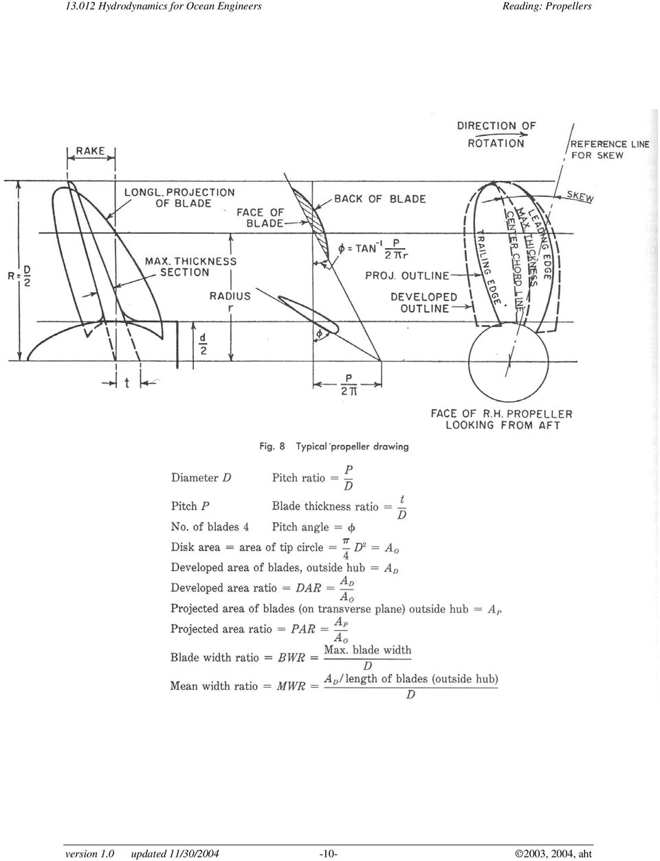
3 Where RPM is the revolutions per minute of the shaft and HP is the shaft horsepower. You can see here that for the same power, a slower turning propeller will generate more thrust. Typically for engines and motors, power and available torque are provided as curves on performance data sheets as a plot of BHP, Torque, and fuel consumption as a function of RPM. Speed of the vessel: We have already laid the foundation for determining the resistance on a full scale ship based on model testing for a desired full scale ship speed. This is of course a function of the ship geometry and an important part of choosing the correct ship propeller. Choosing a Propeller To properly choose a propeller we must first understand some of the basic nomenclature used to describe propeller geometry. Figure 1 is taken from Gilmer and Johnson, Introduction to Naval Architecture. Basic Nomenclature: Hub The hub of a propeller is the solid center disk that mates with the propeller shaft and to which the blades are attached. Ideally the hub should be as small in diameter as possible to obtain maximum thrust, however there is a tradeoff between size and strength. Too small a hub ultimately will not be strong enough. Blades Twisted fins or foils that protrude from the propeller hub. The shape of the blades and the speed at which they are driven dictates the torque a given propeller can deliver. version 1.0 updated 11/30/ , 2004, aht

4 Blade Root and Blade Tip The root of a propeller blade is where the blade attaches to the hub. The tip is the outermost edge of the blade at a point furthest from the propeller shaft. Blade Face and Back The face of a blade is considered to be the high-pressure side, or pressure face of the blade. This is the side that faces aft (backwards) and pushes the water when the vessel is in forward motion. The back of the blade is the low pressure side or the suction face of the blade. This is the side that faces upstream or towards the front of the vessel. Leading and Trailing Edges The leading edge of a propeller blade or any foil is the side that cuts through the fluid. The trailing edge is the downstream edge of the foil. Right Handed vs. Left Handed A propeller s handedness affects its shape. A righthanded propeller rotates clockwise when propelling a vessel forward, as viewed from the stern of the ship. A left-handed propeller rotates counter-clockwise, as viewed from the stern, when in a forward propulsion mode. When viewing a propeller from astern, the leading edges of the blades will always be farther away from you than the trailing edges. The propeller rotates clockwise, and is right-handed, if the leading edges are on the right. A propeller s handedness is fixed. A right-handed propeller can never be exchanged with a left handed propeller, and vice versa. Most single screw vessels (one engine, one propeller) have right-handed propellers and clockwise rotating propeller shafts (as viewed from astern). Single propellers tend to naturally push the vessel to one side when going forward (and the opposite side when in reverse) a right-handed prop will push the stern to starboard when in forward (and port when in reverse). Since Propellers are not ideally designed for reverse propulsion, this effect is somewhat exaggerated when operating a single-screw vessel in reverse. Twin screw vessels have counter rotating propellers with identical specifications. The port (left) side propeller is usually left-handed and the starboard (right) side propeller is usually right-handed. version 1.0 updated 11/30/ , 2004, aht

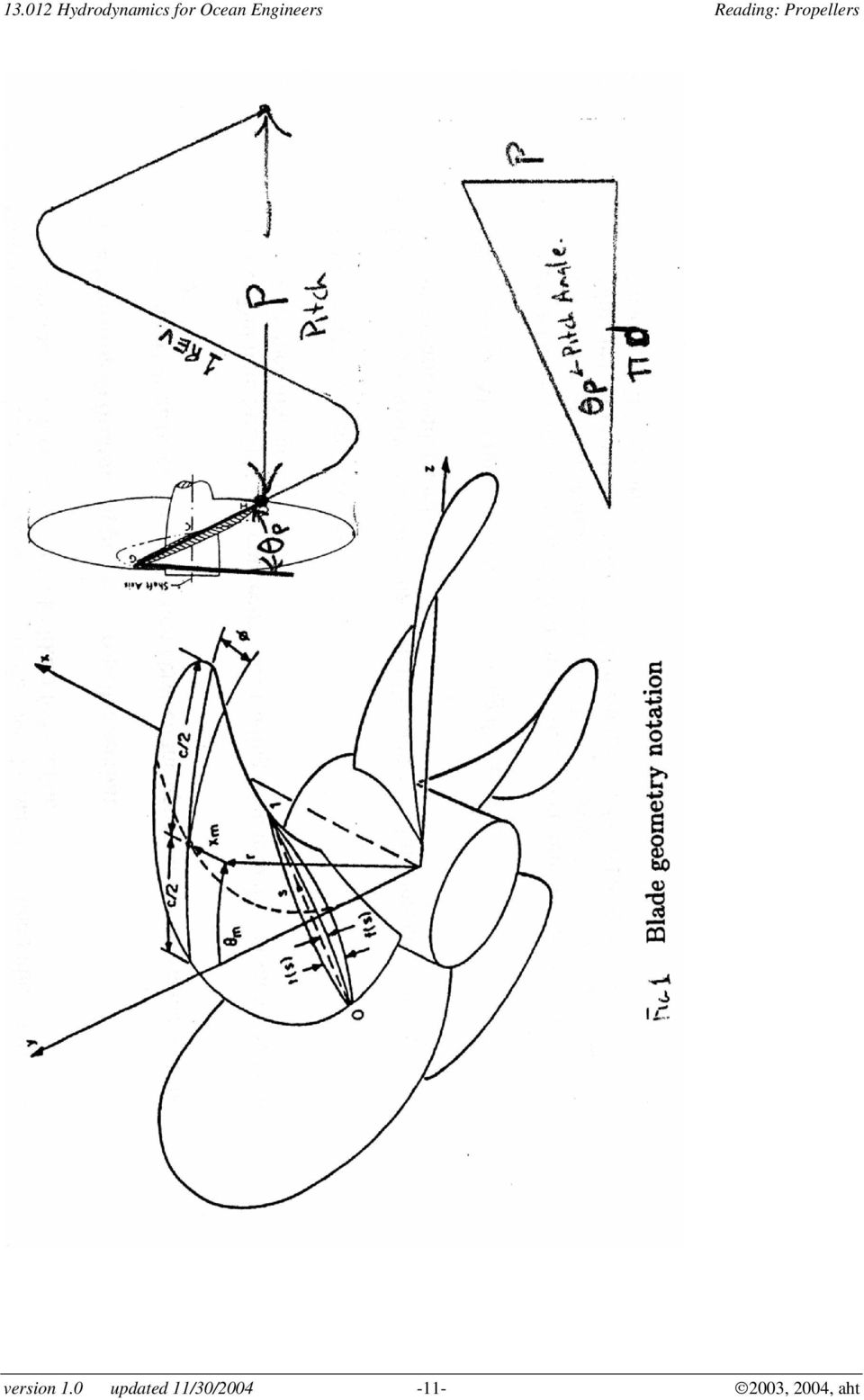
5 Diameter The diameter (or radius) is a crucial geometric parameter in determining the amount of power that a propeller can absorb and deliver, and thus dictating the amount of thrust available for propulsion. With the exception of high speed (35 Knots+) vehicles the diameter is proportional to propeller efficiency (ie. Higher diameter equates to higher efficiency). In high speed vessels, however, larger diameter equates to high drag. For typical vessels a small increase in diameter translates into a dramatic increase in thrust and torque load on the engine shaft, thus the larger the diameter the slower the propeller will turn, limited by structural loading and engine rating. Revolutions per Minute (RPMs) RPM is the number of full turns or rotations of a propeller in one minute. RPM is often designated by the variable N. High values of RPM are typically not efficient except on high speed vessels. For vessels operating under 35Knots speed, it is usual practice to reduce RPM, and increase diameter, to obtain higher torque from a reasonably sized power plant. Achieving low RPM from a typical engine usually requires a reduction gearbox. Pitch The pitch of a propeller is defined similarly to that of a wood or machine screw. It indicates the distance the propeller would drive forward for each full rotation. If a propeller moves forward 10inches for every complete turn it has a 10inch nominal pitch. In reality since the propeller is attached to a shaft it will not actually move forward, but instead propel the ship forward. The distance the ship is propelled forward in one propeller rotation is actually less than the pitch. The difference between the nominal pitch and the actual distance traveled by the vessel in one rotation is called slip. Typically blades are twisted to guarantee constant pitch along the blades from root to tip. Often a pitch ratio will be supplied. This is simply the ratio of pitch to diameter, usually in millimeters, and typically falls between 0.5 and 2.5 with an optimal value for most vessels closer to 0.8 to 1.8. Pitch effectively converts torque of the propeller shaft to thrust by deflecting or accelerating the water astern simple Newton s Second Law. version 1.0 updated 11/30/ , 2004, aht

6 Figure 1 version 1.0 updated 11/30/ , 2004, aht

7 Propeller Section Propeller section: A circular arc section cut through the blade at some radius. When this section is "flattened out" it looks like a foil section (see figure 2) The following definitions apply to a propeller section : Meanline: Half distance along a section between the upper and lower surfaces of the blade Nose-Tail line: Straight line connecting the leading edge meanline point to the trailing edge meanline point. Chordlength: Length of Nose-tail line Camber height: distance between nose-tail line and meanline normal to the nose-tail line (varies with chordwise position) Max. Camber: Maximum camber height along the section Meanline Distribution: A standard distribution of camber height as a function of chordwise position starting at the section leading edge. Quite often these are tabulated forms such as a NACA A=0.8 Meanline, and can be obtained from standard foil literature. Thickness: Section thickness along a line normal to the meanline. Varies with chordwise position Max. Thickness: Maximum section thickness version 1.0 updated 11/30/ , 2004, aht
 Max.")
8 Thickness distribution: A standard distribution of thickness as a function of chord length quite often are tabulated forms such as NACA 66 thickness form that can be obtained from standard foil literature. The following geometry definitions apply to the overall propeller geometry and are a function of radius: Pitch: The axial distance traveled by the section if rotated on revolution ant translated along the section nose-tail line (arc) Midchord line: line produced from the midchords (i.e. Midpoint of section nose tail line) of each section along a propeller blade. Rake: Axial distance from the midchord point at the hub section and the section of interest. Skew or Skew Angle: Tangential component of the angle formed on the propeller between a radial line going through the hub section midchord point and a radial line going through the midchord of the section of interest and projected Figure 2. Propeller blade cross section is similar to an airfoil version 1.0 updated 11/30/ , 2004, aht
 Midchord line: line produced from the midchords (i.e. Midpoint of section nose tail line) of each section along a propeller blade.")
9 version 1.0 updated 11/30/ , 2004, aht

10 version 1.0 updated 11/30/ , 2004, aht
11 version 1.0 updated 11/30/ , 2004, aht
12 Propeller Performance Characterization Dimensional Attributes: Diameter D Overall diameter of the propeller Rotation rate N Rotational speed of the propeller in rev/sec Density ρ Fluid density Thrust T Propeller axial thrust force Torque Q Propeller shaft torque Ship Speed V s Ship velocity Inflow Velocity V a Mean inflow velocity Non-Dimensional Characterization of propeller performance: Advance Coef: J = V a /(ND) Thrust Coef.: K t = T/( ρ N 2 D 4 ) Thrust Coef.: C t = 2T/( ρav 2 a ) (A= Propulsor area) Torque Coef.: K q = Q/( ρ N 2 D 5 ) Propeller Efficiency: η 0 = (T * V a )/(2π N Q) Propulsive Efficiency: η t = (R t * V s )/(2π N Q) R t = Total Ship resistance version 1.0 updated 11/30/ , 2004, aht
 Propeller Efficiency: η 0 = (T * V a )/(2π N Q) Propulsive Efficiency: η t = (R t * V s )/(2π N Q) R t = Total Ship resistance version 1.")
13 Ideal Propellers and the Kramer Diagram Unlike the actuator disc a propeller requires that the power be input into the fluid via a shaft and thus must apply a torque to the fluid. To balance this torque the flow must contain tangential velocity, or swirl, to counteract this torque. The kinetic energy in the swirl velocity, if not recovered by a stator or downstream blade row, is lost. Therefore the efficiency of an ideal propeller will be less than an actuator disc efficiency. For a propeller in uniform flow this ideal efficiency can be computed given the advance coefficient, J, and the thrust coefficient, C t. The graphical chart of these results is depicted in the Kramer diagram, which also has correction for losses due to finite blade number. This chart does NOT include viscous losses and gives the maximum achievable efficiency for a real propeller in uniform inflow. To use Kramer s diagram: Need to Know: T = thrust to propel ship (need to know ship s total resistance) Find C t based on your chosen propeller area. Choose the number of blades Know Va, D, N Use chart: o Start with λ = Absolute advance coefficient (λ = Va/ (π n D) = J/π) o Follow up diagonal line until you hit the horizontal line that corresponds to your number of blades. o Next go DIRECTLY up to the next horizontal line that corresponds to your known value of C t which you calculated earlier. o Then choose the closest efficiency curve or interpolate between curves for η. version 1.0 updated 11/30/ , 2004, aht

14 Hydrodynamics for Ocean Engineers version 1.0 updated 11/30/2004 Reading: Propellers , 2004, aht

15 Propeller Series A common way to choose propellers as a first cut at a design is to choose propellers from a standard propeller series such as the B-series propellers shown below. These are essentially propeller curves for a variety of propellers of varying loading indicated in the form of pitch. If J and K t are known then one can pick the propeller in the series that gives the best efficiency, for example, by reading directly off the chart. Example: Suppose one has a propeller application with the following requirements: Thrust = 14,000 N Ship speed Vs= 10 m/s Density water = 1000kg/m 3 Diameter = 1.0 meters Max. Shaft RPM =600 4-bladed propeller Compute the ideal (actuator disc) efficiency: Ct= 2 (14,000) / (1000* * (1 2 / 4)* 10 2 ) = Ideal efficiency = 2 / (1 + (1.357) ½ ) = or 92.3% Given a maximum Shaft speed of 600 RPM (10 rps) J = 10/10/1 =1 (Lambda=0.318) Ideal prop. Eff. = 0.86 or 86 % Kt= 14000/1000/10/10/1 =0.14 From the B-series Data: J = 1.0 and Kt = 0.14 Gives a P/D= 1.2 and a propeller efficiency of 0.75 or 75% You can see the actual propeller is much less efficient than either the ideal propeller or the actuator disc result. version 1.0 updated 11/30/ , 2004, aht

16 B-Series Propeller Data for Wageningen B 4-55 type propeller series (From Harvald; Resistance and Propulsion of Ships, 1983 ed. Wiley) version 1.0 updated 11/30/ , 2004, aht
 version 1.")
17 Interaction with hull on performance: An actual ship propeller often operates in the wake of a ship as shown below. Therefore the "freestream" velocity as seen by the propeller is lower than the ship speed. The Wake fraction is defined as w= 1 V / V a s and is the percentage of the ship velocity seen at the propeller The propeller, if close to the hull can also induce a low pressure on the hull which increases its drag. Thus the propeller thrust must be higher to overcome this additional drag. The thrust deduction coefficient is defined as: t = 1 R / T t where R t is the total ship resistance and T is the propeller thrust. Note that prop efficiency is simply η 0 = (T * V a )/(2π NQ) version 1.0 updated 11/30/ , 2004, aht

18 and the propulsive efficiency is η t = (R t * V s )/(2π NQ) If the torque in each equation is assumed the same then we can show that η t = (1-t)/(1-w) *η 0 From this result we can see that the propulsive efficiency can increase if the propeller is put in the wake of the ship (if t is small). In fact it is possible to have a propulsive efficiency for a propeller system of greater than 1.0! This doesn't violate any physical laws but merely states that the propeller has "reduced" the ship resistance by taking advantage of its wake. version 1.0 updated 11/30/ , 2004, aht

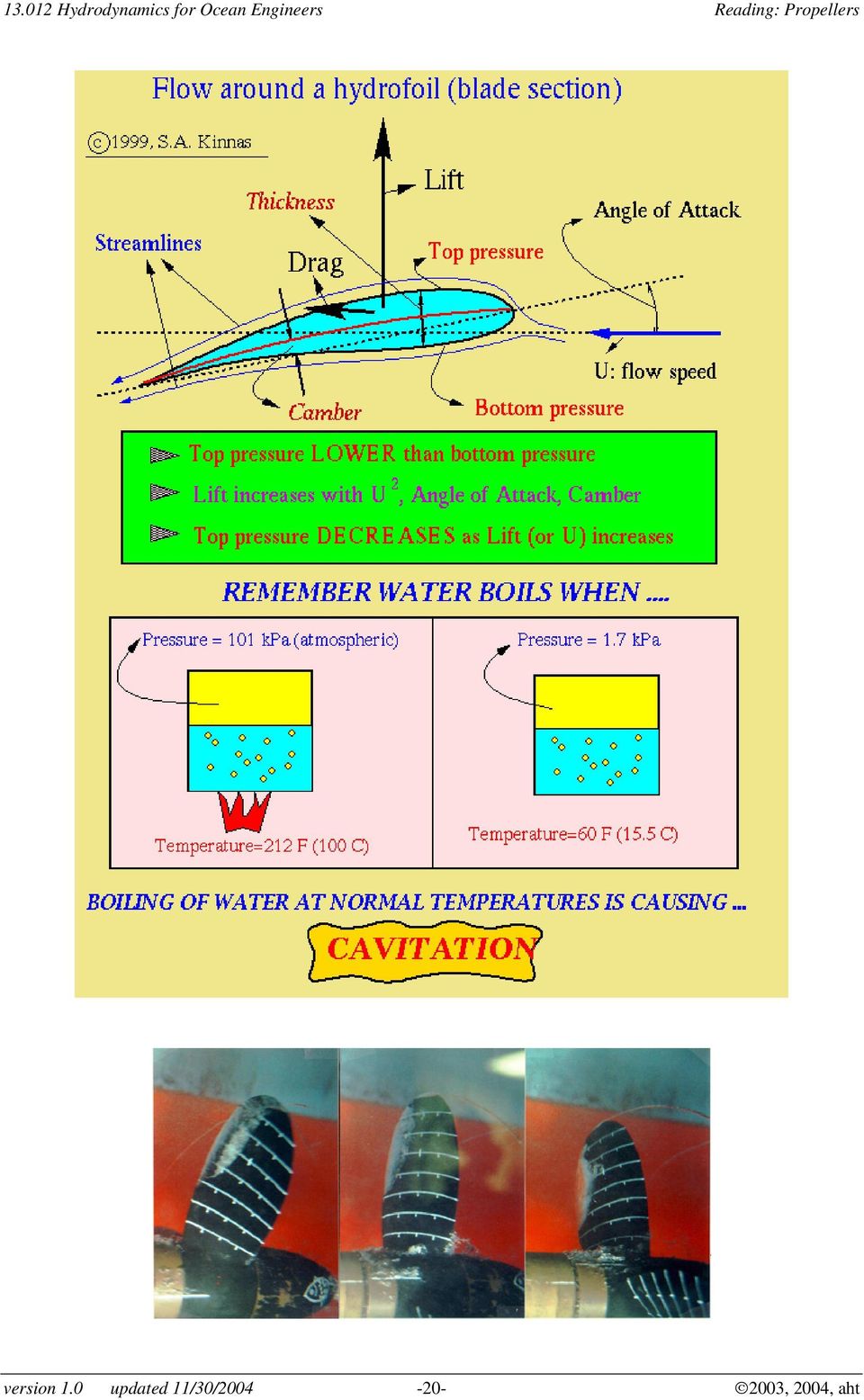
19 Propeller Cavitation Cavitation occurs when the local absolute pressure is less than local vapor pressure for the fluid medium. Cavitation Number (Inflow Velocity Based) is defined as: σ v = 2 (P Pvap)/ ρav a 2 Sometimes Propeller Cavitation Number is defined based on Propeller tip Speed: σ ND = (P Pvap)/ ( ρ N 2 D 2 ) The Critical measurement for cavitation performance is the cavitation inception point which is the conditions (i.e. Cavitation number) for which cavitation is first observed anywhere on the propeller. Typically the Inception cavitation number as a function of Kt or J is plotted for a given propeller which defines the cavitation free operation boundary. This boundary typically has a bucket shape which is referred to as the cavitation bucket. version 1.0 updated 11/30/ , 2004, aht

20 version 1.0 updated 11/30/ , 2004, aht
Technology guidelines for efficient design and operation of ship propulsors by Teus van Beek, Propulsor Technology, Wärtsilä Propulsion Netherlands BV
 The Ship Power Supplier Technology guidelines for efficient design and operation of ship propulsors by Teus van Beek, Propulsor Technology, Wärtsilä Propulsion Netherlands BV Introduction The number of
CENTRIFUGAL PUMP OVERVIEW Presented by Matt Prosoli Of Pumps Plus Inc.
 CENTRIFUGAL PUMP OVERVIEW Presented by Matt Prosoli Of Pumps Plus Inc. 1 Centrifugal Pump- Definition Centrifugal Pump can be defined as a mechanical device used to transfer liquid of various types. As
Practice Problems on Boundary Layers. Answer(s): D = 107 N D = 152 N. C. Wassgren, Purdue University Page 1 of 17 Last Updated: 2010 Nov 22
: D = 107 N D = 152 N. C. Wassgren, Purdue University Page 1 of 17 Last Updated: 2010 Nov 22") BL_01 A thin flat plate 55 by 110 cm is immersed in a 6 m/s stream of SAE 10 oil at 20 C. Compute the total skin friction drag if the stream is parallel to (a) the long side and (b) the short side. D =
BL_01 A thin flat plate 55 by 110 cm is immersed in a 6 m/s stream of SAE 10 oil at 20 C. Compute the total skin friction drag if the stream is parallel to (a) the long side and (b) the short side. D =
NACA airfoil geometrical construction
 The NACA airfoil series The early NACA airfoil series, the 4-digit, 5-digit, and modified 4-/5-digit, were generated using analytical equations that describe the camber (curvature) of the mean-line (geometric
CFD ANALYSIS OF CONTROLLABLE PITCH PROPELLER USED IN MARINE VEHICLE
 CFD ANALYSIS OF CONROLLABLE PICH PROPELLER USED IN MARINE VEHICLE Aditya Kolakoti 1,.V.K.Bhanuprakash 2 & H.N.Das 3 1 M.E in Marine Engineering And Mechanical Handling, Dept of Marine Engineering, Andhra
Electric Motors and Drives
 EML 2322L MAE Design and Manufacturing Laboratory Electric Motors and Drives To calculate the peak power and torque produced by an electric motor, you will need to know the following: Motor supply voltage,
Lift and Drag on an Airfoil ME 123: Mechanical Engineering Laboratory II: Fluids
 Lift and Drag on an Airfoil ME 123: Mechanical Engineering Laboratory II: Fluids Dr. J. M. Meyers Dr. D. G. Fletcher Dr. Y. Dubief 1. Introduction In this lab the characteristics of airfoil lift, drag,
Solution: Angular velocity in consistent units (Table 8.1): 753.8. Velocity of a point on the disk: Rate at which bits pass by the read/write head:
: 753.8. Velocity of a point on the disk: Rate at which bits pass by the read/write head:") Problem P8: The disk in a computer hard drive spins at 7200 rpm At the radius of 0 mm, a stream of data is magnetically written on the disk, and the spacing between data bits is 25 μm Determine the number
Problem P8: The disk in a computer hard drive spins at 7200 rpm At the radius of 0 mm, a stream of data is magnetically written on the disk, and the spacing between data bits is 25 μm Determine the number
Propeller Selection For Boats and Small Ships
 E Marine Training - Prop Matching - February, 2005 1 Propeller Selection For Boats and Small Ships Chris Barry This course is intended to cover the basic elements of marine propulsion, especially propellers
GEAROLOGY 4-1 WORMS AND WORM GEARS WORMS AND WORM GEARS
 GEAROLOGY 4-1 4 4-2 GEAROLOGY COMMON APPLICATIONS: Worm and worm gear sets are used in many, everyday products including: electrical mixers, hubometers, right Now that you have an understanding of two
Resistance & Propulsion (1) MAR 2010. Presentation of ships wake
 MAR 2010. Presentation of ships wake") Resistance & Propulsion (1) MAR 2010 Presentation of ships wake Wake - Overview Flow around a propeller is affected by the presence of a hull Potential and viscous nature of the boundary layer contribute
Resistance & Propulsion (1) MAR 2010 Presentation of ships wake Wake - Overview Flow around a propeller is affected by the presence of a hull Potential and viscous nature of the boundary layer contribute
IPS Inboard performance system. Volvo Penta IPS, the future for fast vessels
 IPS, the future for fast vessels 1 dec 2010 Save fuel and reduce environmental impact 2 dec 2010 Best efficiency with Contra Rotating propellers Double blade area means smaller prop diameter for same output
Chapter 3.5: Fans and Blowers
 Part I: Objective type questions and answers Chapter 3.5: Fans and Blowers 1. The parameter used by ASME to define fans, blowers and compressors is a) Fan ration b) Specific ratio c) Blade ratio d) Twist
Propellers. Inboard propellers and speed calculation Marine Engines 2.1L 16L
 Propellers Inboard propellers and speed calculation Marine Engines 2.1L 16L Foreword The purpose of this information is to provide installers, designers or users with a simple and effective help in choosing
Numerical Study on the Influence of Boss Cap Fins on Efficiency of Controllable-pitch Propeller
 J. Marine Sci. Appl. (2013) 12: 13-20 DOI: 10.1007/s11804-013-1166-9 Numerical Study on the Influence of Boss Cap Fins on Efficiency of Controllable-pitch Propeller Ying Xiong 1, Zhanzhi Wang 1* and Wanjiang
MAN Diesel & Turbo. Frederik Carstens Head of Offshore Sales Marine Medium Speed. Frederik Carstens & Karsten Borneman
 Frederik Carstens Head of Offshore Sales Marine Medium Speed < 1 > Disclaimer All data provided on the following slides is for information purposes only, explicitly non-binding and subject to changes without
Unit 4 Practice Test: Rotational Motion
 Unit 4 Practice Test: Rotational Motion Multiple Guess Identify the letter of the choice that best completes the statement or answers the question. 1. How would an angle in radians be converted to an angle
ROVs in a Bucket Building an Underwater Robot. 3.0 ROV Thrusters & Propeller Attachment. 3.1 Propulsion
 3.0 ROV Thrusters & Propeller Attachment 3.1 Propulsion ROV s move forward and back, up and down, and to the left and right. They can make all of these moves without the benefit of a rudder. With three
Propeller Efficiency. Rule of Thumb. David F. Rogers, PhD, ATP
 Propeller Efficiency Rule of Thumb David F. Rogers, PhD, ATP Theoretically the most efficient propeller is a large diameter, slowly turning single blade propeller. Here, think the Osprey or helicopters.
Relevance of Modern Optimization Methods in Turbo Machinery Applications
 Relevance of Modern Optimization Methods in Turbo Machinery Applications - From Analytical Models via Three Dimensional Multidisciplinary Approaches to the Optimization of a Wind Turbine - Prof. Dr. Ing.
Application of CFD in connection with ship design
 DANSIS meeting Lyngby, 13 May 2009 Application of CFD in connection with ship design www.force.dk Background Method Examples Summary Claus Daniel Simonsen FORCE Technology Background When a ship, which
FLUID FLOW STREAMLINE LAMINAR FLOW TURBULENT FLOW REYNOLDS NUMBER
 VISUAL PHYSICS School of Physics University of Sydney Australia FLUID FLOW STREAMLINE LAMINAR FLOW TURBULENT FLOW REYNOLDS NUMBER? What type of fluid flow is observed? The above pictures show how the effect
GEAROLOGY 2-1 SPUR GEARS SPUR GEARS
 GEAROLOGY 2-1 2 2-2 GEAROLOGY COMMON APPLICATIONS: Spur gears are used to Now that you ve been introduced to both Boston Gear and some of the basics of our Gearology course which we like to call Power
A new era in yacht power. For Vessels up to 100+ feet
 Volvo Penta IPS A new era in yacht power For Vessels up to 100+ feet From a revolution to a The unique Benefits of Volvo Penta IPS: 40% longer cruising range 20% higher top speed 30% reduced fuel consumption
DRAFTING MANUAL. Gears (Bevel and Hypoid) Drafting Practice
 Drafting Practice") Page 1 1.0 General This section provides the basis for uniformity in engineering gears drawings and their technical data for gears with intersecting axes (bevel gears), and nonparallel, nonintersecting
Page 1 1.0 General This section provides the basis for uniformity in engineering gears drawings and their technical data for gears with intersecting axes (bevel gears), and nonparallel, nonintersecting
AERODYNAMIC ANALYSIS OF BLADE 1.5 KW OF DUAL ROTOR HORIZONTAL AXIS WIND TURBINE
 AERODYNAMIC ANALYSIS OF BLADE 1.5 KW OF DUAL ROTOR HORIZONTAL AXIS WIND TURBINE HITENDRA KURMI Research scholar, School of Energy and Environmental Managment,UTD, RGPV Bhopal,MP,INDIA [email protected]
Torque and Rotary Motion
 Torque and Rotary Motion Name Partner Introduction Motion in a circle is a straight-forward extension of linear motion. According to the textbook, all you have to do is replace displacement, velocity,
EVALUAT ING ACADEMIC READINESS FOR APPRENTICESHIP TRAINING Revised for ACCESS TO APPRENTICESHIP
 EVALUAT ING ACADEMIC READINESS FOR APPRENTICESHIP TRAINING for ACCESS TO APPRENTICESHIP SCIENCE SKILLS SIMPLE MACHINES & MECHANICAL ADVANTAGE AN ACADEMIC SKILLS MANUAL for The Construction Trades: Mechanical
NACA Nomenclature NACA 2421. NACA Airfoils. Definitions: Airfoil Geometry
 0.40 m 0.21 m 0.02 m NACA Airfoils 6-Feb-08 AE 315 Lesson 10: Airfoil nomenclature and properties 1 Definitions: Airfoil Geometry z Mean camber line Chord line x Chord x=0 x=c Leading edge Trailing edge
Performance. Power Plant Output in Terms of Thrust - General - Arbitrary Drag Polar
 Performance 11. Level Flight Performance and Level flight Envelope We are interested in determining the maximum and minimum speeds that an aircraft can fly in level flight. If we do this for all altitudes,
CFD Analysis of a Propeller Flow and Cavitation
 CFD Analysis of a Propeller Flow and Cavitation S. Subhas PG student NITW V F Saji Scientist C N S T L Visakhapatnam S. Ramakrishna GVP College of Engineering (A) Visakhapatnam H. N Das Scientist F N S
Simple Analysis for Brushless DC Motors Case Study: Razor Scooter Wheel Motor
 Simple Analysis for Brushless DC Motors Case Study: Razor Scooter Wheel Motor At first glance, a brushless direct-current (BLDC) motor might seem more complicated than a permanent magnet brushed DC motor,
COMPUTATIONAL FLUID DYNAMICS (CFD) ANALYSIS OF INTERMEDIATE PRESSURE STEAM TURBINE
 ANALYSIS OF INTERMEDIATE PRESSURE STEAM TURBINE") Research Paper ISSN 2278 0149 www.ijmerr.com Vol. 3, No. 4, October, 2014 2014 IJMERR. All Rights Reserved COMPUTATIONAL FLUID DYNAMICS (CFD) ANALYSIS OF INTERMEDIATE PRESSURE STEAM TURBINE Shivakumar
Research Paper ISSN 2278 0149 www.ijmerr.com Vol. 3, No. 4, October, 2014 2014 IJMERR. All Rights Reserved COMPUTATIONAL FLUID DYNAMICS (CFD) ANALYSIS OF INTERMEDIATE PRESSURE STEAM TURBINE Shivakumar
CENTRIFUGAL PUMP SELECTION, SIZING, AND INTERPRETATION OF PERFORMANCE CURVES
 CENTRIFUGAL PUMP SELECTION, SIZING, AND INTERPRETATION OF PERFORMANCE CURVES 4.0 PUMP CLASSES Pumps may be classified in two general types, dynamic and positive displacement. Positive displacement pumps
SIMPLIFIED METHOD FOR ESTIMATING THE FLIGHT PERFORMANCE OF A HOBBY ROCKET
 SIMPLIFIED METHOD FOR ESTIMATING THE FLIGHT PERFORMANCE OF A HOBBY ROCKET WWW.NAKKA-ROCKETRY.NET February 007 Rev.1 March 007 1 Introduction As part of the design process for a hobby rocket, it is very
Computational Fluid Dynamics Investigation of Two Surfboard Fin Configurations.
 Computational Fluid Dynamics Investigation of Two Surfboard Fin Configurations. By: Anthony Livanos (10408690) Supervisor: Dr Philippa O Neil Faculty of Engineering University of Western Australia For
Unit 24: Applications of Pneumatics and Hydraulics
 Unit 24: Applications of Pneumatics and Hydraulics Unit code: J/601/1496 QCF level: 4 Credit value: 15 OUTCOME 2 TUTORIAL 3 HYDRAULIC AND PNEUMATIC MOTORS The material needed for outcome 2 is very extensive
Linear Motion vs. Rotational Motion
 Linear Motion vs. Rotational Motion Linear motion involves an object moving from one point to another in a straight line. Rotational motion involves an object rotating about an axis. Examples include a
Center of Gravity. We touched on this briefly in chapter 7! x 2
 Center of Gravity We touched on this briefly in chapter 7! x 1 x 2 cm m 1 m 2 This was for what is known as discrete objects. Discrete refers to the fact that the two objects separated and individual.
The INSEAN E779a Propeller Test Case: a Database For CFD Validation
 The INSEAN E779a Propeller Test Case: a Database For CFD Validation G.Calcagno,F. Di Felice, M. Felli,S. Franchi, F.Pereira, F.Salvatore INSEAN (Italian Ship Model Basin), via di Vallerano 139, 00128 Rome,
Belt Drives and Chain Drives. Power Train. Power Train
 Belt Drives and Chain Drives Material comes for Mott, 2002 and Kurtz, 1999 Power Train A power train transmits power from an engine or motor to the load. Some of the most common power trains include: Flexible
MAXIMIZING THE OUTPUT OF YOUR BRAKES Getting Your Pedal Geometry Right
 MATCO mfg 2361 S 1560 West Woods Cross, UT 84087 801-335-0582 801-335-0581 (F) www.matcomfg.com MAXIMIZING THE OUTPUT OF YOUR BRAKES Getting Your Pedal Geometry Right Brake Specifications Energy Rating
Gear Trains. Introduction:
 Gear Trains Introduction: Sometimes, two or more gears are made to mesh with each other to transmit power from one shaft to another. Such a combination is called gear train or train of toothed wheels.
Conceptual: 1, 3, 5, 6, 8, 16, 18, 19. Problems: 4, 6, 8, 11, 16, 20, 23, 27, 34, 41, 45, 56, 60, 65. Conceptual Questions
 Conceptual: 1, 3, 5, 6, 8, 16, 18, 19 Problems: 4, 6, 8, 11, 16, 20, 23, 27, 34, 41, 45, 56, 60, 65 Conceptual Questions 1. The magnetic field cannot be described as the magnetic force per unit charge
DC Motor / Propeller Matching 3 Mar 05 Lab 5 Lecture Notes
 DC Motor / Propeller Matching 3 Mar 05 Lab 5 Lecture Notes Nomenclature prop thrust prop torque m motor torque P shaft shaft power P elec electrical power C thrust coefficient based on tip speed C P power
Why Lead Screws are the Best Fit for Many Linear Motion Applications - and How to Rightly Apply Them
 Why Lead Screws are the Best Fit for Many Linear Motion Applications - and How to Rightly Apply Them Robert Lipsett, Engineering Manager, Thomson BSA Thomson Industries, Inc. San Jose, CA 800.882.8857
Chapter 10 Rotational Motion. Copyright 2009 Pearson Education, Inc.
 Chapter 10 Rotational Motion Angular Quantities Units of Chapter 10 Vector Nature of Angular Quantities Constant Angular Acceleration Torque Rotational Dynamics; Torque and Rotational Inertia Solving Problems
Automatic Transmission Basics
 Automatic Transmission Basics Lesson Objectives 1. Describe the function of the torque converter. 2. Identify the three major components of the torque converter that contribute to the multiplication of
ZF 301 A. Marine Propulsion Systems
 Marine Propulsion Systems 10 Down angle, direct mount marine transmission. Description Robust design also withstands continuous duty in workboat applications. Fully works tested, reliable and simple to
Fric-3. force F k and the equation (4.2) may be used. The sense of F k is opposite
 may be used. The sense of F k is opposite") 4. FRICTION 4.1 Laws of friction. We know from experience that when two bodies tend to slide on each other a resisting force appears at their surface of contact which opposes their relative motion. The
4. FRICTION 4.1 Laws of friction. We know from experience that when two bodies tend to slide on each other a resisting force appears at their surface of contact which opposes their relative motion. The
Module 2 - GEARS Lecture 7 - SPUR GEAR DESIGN
 Module 2 - GEARS Lecture 7 - SPUR GEAR DESIGN Contents 7.1 Spur gear tooth force analysis 7.2 Spur gear - tooth stresses 7.3 Tooth bending stress Lewis equation 7.4 Tooth bending stress AGMA procedure
SOLID MECHANICS TUTORIAL MECHANISMS KINEMATICS - VELOCITY AND ACCELERATION DIAGRAMS
 SOLID MECHANICS TUTORIAL MECHANISMS KINEMATICS - VELOCITY AND ACCELERATION DIAGRAMS This work covers elements of the syllabus for the Engineering Council exams C105 Mechanical and Structural Engineering
Dimensional analysis is a method for reducing the number and complexity of experimental variables that affect a given physical phenomena.
 Dimensional Analysis and Similarity Dimensional analysis is very useful for planning, presentation, and interpretation of experimental data. As discussed previously, most practical fluid mechanics problems
Propeller Design and Propulsion Concepts for Ship Operation in Off- Design Conditions
 Second International Symposium on Marine Propulsors smp 11, Hamburg, Germany, June 2011 Propeller Design and Propulsion Concepts for Ship Operation in Off- Design Conditions Thomas Stoye Flensburger Schiffbau-Gesellschaft
2. Parallel pump system Q(pump) = 300 gpm, h p = 270 ft for each of the two pumps
 = 300 gpm, h p = 270 ft for each of the two pumps") Pumping Systems: Parallel and Series Configurations For some piping system designs, it may be desirable to consider a multiple pump system to meet the design requirements. Two typical options include parallel
Pumping Systems: Parallel and Series Configurations For some piping system designs, it may be desirable to consider a multiple pump system to meet the design requirements. Two typical options include parallel
Experiment 3 Pipe Friction
 EML 316L Experiment 3 Pipe Friction Laboratory Manual Mechanical and Materials Engineering Department College of Engineering FLORIDA INTERNATIONAL UNIVERSITY Nomenclature Symbol Description Unit A cross-sectional
ZF W320 Vertical offset, direct mount marine transmission.
 Marine Propulsion Systems Vertical offset, direct mount marine transmission. Maximum Input** Duty kw hp RPM Medium 425 570 2400 Continuous 357 479 2400 ** Must not be exceeded Description Robust design
FAN PROTECTION AGAINST STALLING PHENOMENON
 FAN PROTECTION AGAINST STALLING PHENOMENON Roberto Arias Álvarez 1 Javier Fernández López 2 2 1 ZITRON Technical Director [email protected] ZITRON Technical Pre Sales Management [email protected]
ZF 220 A 10 Down angle, direct mount marine transmission.
 Marine Propulsion Systems 10 Down angle, direct mount marine transmission. Maximum Input** Duty kw hp RPM Pleasure 419 562 4500 Light 394 528 4500 Medium 335 449 4500 Continuous 192 258 3200 ** Must not
ZF W325 Vertical offset, direct mount marine transmission.
 Marine Propulsion Systems Vertical offset, direct mount marine transmission. Maximum Input** Duty kw hp RPM Medium 507 680 2600 Continuous 430 577 2600 ** Must not be exceeded Description Robust design
Pumps: Convert mechanical energy (often developed from electrical source) into hydraulic energy (position, pressure and kinetic energy).
 into hydraulic energy (position, pressure and kinetic energy).") HYDRAULIC MACHINES Used to convert between hydraulic and mechanical energies. Pumps: Convert mechanical energy (often developed from electrical source) into hydraulic energy (position, pressure and kinetic
HYDRAULIC MACHINES Used to convert between hydraulic and mechanical energies. Pumps: Convert mechanical energy (often developed from electrical source) into hydraulic energy (position, pressure and kinetic
Mechanical Principles
 Unit 4: Mechanical Principles Unit code: F/60/450 QCF level: 5 Credit value: 5 OUTCOME 3 POWER TRANSMISSION TUTORIAL BELT DRIVES 3 Power Transmission Belt drives: flat and v-section belts; limiting coefficient
Azimuth thrusters. propulsors
 Azimuth s Rolls-Royce is a global leader in the supply of azimuth s. In an azimuth the propeller rotates 360 around the vertical axis so the unit provides propulsion, steering and positioning thrust for
Practice Problems on Pumps. Answer(s): Q 2 = 1850 gpm H 2 = 41.7 ft W = 24.1 hp. C. Wassgren, Purdue University Page 1 of 16 Last Updated: 2010 Oct 29
: Q 2 = 1850 gpm H 2 = 41.7 ft W = 24.1 hp. C. Wassgren, Purdue University Page 1 of 16 Last Updated: 2010 Oct 29") _02 A centrifugal with a 12 in. diameter impeller requires a power input of 60 hp when the flowrate is 3200 gpm against a 60 ft head. The impeller is changed to one with a 10 in. diameter. Determine the
_02 A centrifugal with a 12 in. diameter impeller requires a power input of 60 hp when the flowrate is 3200 gpm against a 60 ft head. The impeller is changed to one with a 10 in. diameter. Determine the
ZF 286 A 7 Down angle, direct mount marine transmission.
 Marine Propulsion Systems 7 Down angle, direct mount marine transmission. Maximum Input** Duty kw hp RPM Pleasure 566 758 3300 Light 509 682 3300 Medium 380 509 3300 Continuous 345 463 3300 ** Must not
The Pressure Velocity (PV) Relationship for Lead Screws
 Relationship for Lead Screws") The Pressure Velocity (PV) Relationship for Lead Screws Robert Lipsett, Engineering Manager Thomson Industries, Inc. Wood Dale, IL 540-633-3549 www.thomsonlinear.com The Pressure Velocity (PV) factor is
The Pressure Velocity (PV) Relationship for Lead Screws Robert Lipsett, Engineering Manager Thomson Industries, Inc. Wood Dale, IL 540-633-3549 www.thomsonlinear.com The Pressure Velocity (PV) factor is
Chapter 5 Using Newton s Laws: Friction, Circular Motion, Drag Forces. Copyright 2009 Pearson Education, Inc.
 Chapter 5 Using Newton s Laws: Friction, Circular Motion, Drag Forces Units of Chapter 5 Applications of Newton s Laws Involving Friction Uniform Circular Motion Kinematics Dynamics of Uniform Circular
Waterjets. propulsors. courtesy of Austal
 Waterjets The Rolls-Royce Kamewa waterjet range is the broadest in the business. Manufactured in aluminium and stainless steel, they are available in powers from kw to above 36MW. Using the latest design
Solution Derivations for Capa #11
 Solution Derivations for Capa #11 1) A horizontal circular platform (M = 128.1 kg, r = 3.11 m) rotates about a frictionless vertical axle. A student (m = 68.3 kg) walks slowly from the rim of the platform
Chapter 2 Lead Screws
 Chapter 2 Lead Screws 2.1 Screw Threads The screw is the last machine to joint the ranks of the six fundamental simple machines. It has a history that stretches back to the ancient times. A very interesting
Wind Energy Math Calculations Calculating the Tip Speed Ratio of Your Wind Turbine
 Wind Energy Math Calculations Calculating the Tip Speed Ratio of Your Wind Turbine The Tip Speed Ratio (TSR) is an extremely important factor in wind turbine design. TSR refers to the ratio between the
What is a Mouse-Trap
 What is a Mouse-Trap Car and How does it Work? A mouse-trap car is a vehicle that is powered by the energy that can be stored in a wound up mouse-trap spring. The most basic design is as follows: a string
HUMAN POWERED SUBMARINE PICUA II 2011
 HUMAN POWERED SUBMARINE PICUA II 2011 design report 2011 2 table of contents D= design, A= analysis, F= fabrication I. Universidad Simón Bolívar (short introduction) 5 Page II. HPS-USB 2009 Team - Chain
Design and Characterization of a Small Wind Turbine Model equipped with a Pitching System
 Design and Characterization of a Small Wind Turbine Model equipped with a Pitching System In Partial Fulfilment of the Requirements for the degree Master of Science in Engineering Renewable Energy and
Tips For Selecting DC Motors For Your Mobile Robot
 Tips For Selecting DC Motors For Your Mobile Robot By AJ Neal When building a mobile robot, selecting the drive motors is one of the most important decisions you will make. It is a perfect example of an
Selecting and Sizing Ball Screw Drives
 Selecting and Sizing Ball Screw Drives Jeff G. Johnson, Product Engineer Thomson Industries, Inc. Wood Dale, IL 540-633-3549 www.thomsonlinear.com [email protected] Fig 1: Ball screw drive is a
Fluid Mechanics Prof. S. K. Som Department of Mechanical Engineering Indian Institute of Technology, Kharagpur
 Fluid Mechanics Prof. S. K. Som Department of Mechanical Engineering Indian Institute of Technology, Kharagpur Lecture - 20 Conservation Equations in Fluid Flow Part VIII Good morning. I welcome you all
Application Information
 Moog Components Group manufactures a comprehensive line of brush-type and brushless motors, as well as brushless controllers. The purpose of this document is to provide a guide for the selection and application
Slide 10.1. Basic system Models
 Slide 10.1 Basic system Models Objectives: Devise Models from basic building blocks of mechanical, electrical, fluid and thermal systems Recognize analogies between mechanical, electrical, fluid and thermal
KINETIC ENERGY RECOVERY SYSTEM BY MEANS OF FLYWHEEL ENERGY STORAGE
 ADVANCED ENGINEERING 3(2009)1, ISSN 1846-5900 KINETIC ENERGY RECOVERY SYSTEM BY MEANS OF FLYWHEEL ENERGY STORAGE Cibulka, J. Abstract: This paper deals with the design of Kinetic Energy Recovery Systems
DOUBLE DRUM TRACTION WINCH SYSTEMS FOR OCEANOGRAPHIC RESEARCH 1.0 TRACTION WINCH SYSTEM ADVANTAGES 11-2
 Chapter 11 DOUBLE DRUM TRACTION WINCH SYSTEMS FOR OCEANOGRAPHIC RESEARCH James Stasny 1.0 TRACTION WINCH SYSTEM ADVANTAGES 11-2 2.0 THEORY OF OPERATION 11-3 3.0 ADVANTAGES IN TRACTION WINCH SYSTEM DESIGN/
Wind Turbine Power Calculations
 Wind Turbine Power Calculations RWE npower renewables Mechanical and Electrical Engineering Power Industry INTRODUCTION RWE npower is a leading integrated UK energy company and is part of the RWE Group,
Design Considerations for Water-Bottle Rockets. The next few pages are provided to help in the design of your water-bottle rocket.
 Acceleration= Force OVER Mass Design Considerations for Water-Bottle Rockets The next few pages are provided to help in the design of your water-bottle rocket. Newton s First Law: Objects at rest will
To provide insight into the physics of arrow flight and show how archers adapt their equipment to maximize effectiveness.
 The Science of Archery Godai Katsunaga Purpose To provide insight into the physics of arrow flight and show how archers adapt their equipment to maximize effectiveness. Archery Archery is one of the events
Awell-known lecture demonstration1
 Acceleration of a Pulled Spool Carl E. Mungan, Physics Department, U.S. Naval Academy, Annapolis, MD 40-506; [email protected] Awell-known lecture demonstration consists of pulling a spool by the free end
ZF 85 IV. Marine Propulsion Systems
 Marine Propulsion Systems 12 V-drive, direct mount marine transmission. Maximum Input** Duty kw hp RPM Pleasure 389 522 3500 Light 365 489 3500 Medium 311 416 3500 Continuous 232 311 3200 ** Must not be
Introduction to Linear Actuators: Precision Linear Motion Accomplished Easily and Economically
 Introduction to Linear Actuators: Precision Linear Motion Accomplished Easily and Economically Part 1 of 2 When students are trained in classic mechanical engineering, they are taught to construct a system
SYNCHRONOUS MACHINES
 SYNCHRONOUS MACHINES The geometry of a synchronous machine is quite similar to that of the induction machine. The stator core and windings of a three-phase synchronous machine are practically identical
Module 9: Basics of Pumps and Hydraulics Instructor Guide
 Module 9: Basics of Pumps and Hydraulics Instructor Guide Activities for Unit 1 Basic Hydraulics Activity 1.1: Convert 45 psi to feet of head. 45 psis x 1 ft. = 103.8 ft 0.433 psi Activity 1.2: Determine
The Effects of Wheelbase and Track on Vehicle Dynamics. Automotive vehicles move by delivering rotational forces from the engine to
 The Effects of Wheelbase and Track on Vehicle Dynamics Automotive vehicles move by delivering rotational forces from the engine to wheels. The wheels push in the opposite direction of the motion of the
How do sails work? Article by Paul Bogataj
 How do sails work? Article by Paul Bogataj Sails are wings that use the wind to generate a force to move a boat. The following explanation of how this occurs can help understand how to maximize the performance
DIRECT CURRENT GENERATORS
 DIRECT CURRENT GENERATORS Revision 12:50 14 Nov 05 INTRODUCTION A generator is a machine that converts mechanical energy into electrical energy by using the principle of magnetic induction. This principle
NUMERICAL ANALYSIS OF WELLS TURBINE FOR WAVE POWER CONVERSION
 Engineering Review Vol. 32, Issue 3, 141-146, 2012. 141 NUMERICAL ANALYSIS OF WELLS TURBINE FOR WAVE POWER CONVERSION Z. 1* L. 1 V. 2 M. 1 1 Department of Fluid Mechanics and Computational Engineering,
ZF 25. Marine Propulsion Systems
 Marine Propulsion Systems Vertical offset, direct mount marine transmission. Description Reverse reduction marine transmission with hydraulically actuated multi-disc clutches. Suitable for high performance
CFturbo Modern turbomachinery design software
 COMPRESSOR Tech Magazine CFturbo Modern turbomachinery design software Designing new compressors from scratch and compressor redesign By Ralph-Peter Mueller & Gero Kreuzfeld Ralph-Peter Mueller and Gero
Natural Convection. Buoyancy force
 Natural Convection In natural convection, the fluid motion occurs by natural means such as buoyancy. Since the fluid velocity associated with natural convection is relatively low, the heat transfer coefficient
User s Guide by David Burch
 TrueWind by David Burch About TrueWind...2 How to use TrueWind...3 Definitions Wind direction...4 Apparent wind...4 Apparent wind angle...4 Apparent wind speed... 5 True wind angle... 5 True wind speed...
Useful Motor/Torque Equations for EML2322L
 Useful Motor/Torque Equations for EML2322L Force (Newtons) F = m x a m = mass (kg) a = acceleration (m/s 2 ) Motor Torque (Newton-meters) T = F x d F = force (Newtons) d = moment arm (meters) Power (Watts)
Ship propulsion by renewable energies available at sea: Innovations for utilisation of wind and waves
 Ship propulsion by renewable energies available at sea: Innovations for utilisation of wind and waves Dr. rer. nat. Jörg Sommer Januar 2013 Preliminary remark 1 The next-but-one generation of vehicles
AE 430 - Stability and Control of Aerospace Vehicles
 AE 430 - Stability and Control of Aerospace Vehicles Atmospheric Flight Mechanics 1 Atmospheric Flight Mechanics Performance Performance characteristics (range, endurance, rate of climb, takeoff and landing