Geometrical Dimensioning & Tolerancing (GD&T)
|
|
|
- Leo Todd
- 9 years ago
- Views:
Transcription
1 MEM 201 Fundamentals of Computer Aided Design Geometrical Dimensioning & Tolerancing (GD&T)

2 Today s Objectives.. Tolerances and why do we need them. Different types of tolerances. To learn how to effectively tolerance parts in engineering drawings. Allowance/Clearance Expressing tolerances in AutoCAD.

3 Tolerancing Definition: Allowance for a specific variation in the size and geometry of part. Why is it needed: No one or thing is perfect! Hence, engineers have come up with a way to make things close to perfect by specifying Tolerances! Since variation from the drawing is inevitable the acceptable degree of variation must be specified. Large variation may affect the functionality of the part Small variation will effect the cost of the part requires precise manufacturing. requires inspection and the rejection of parts.

4 When does Tolerances become important Assemblies: Parts will often not fit together if their dimensions do not fall with in a certain range of values. Interchangeability: If a replacement part is used it must be a duplicate of the original part within certain limits of deviation. The relationship between functionality and size or shape of an object varies from part to part. Tolerances do not affect its function Tolerances are important here!

5 Food for thought: Tolerance levels in this mechanism?

6 Tolerance in relation to $$$$ Cost generally increases with smaller tolerance Small tolerances cause an exponential increase in cost Therefore your duty as an engineer have to consider : Do you need Φ1.0001in or is 1.01in good enough? Parts with small tolerances often require special methods of manufacturing. Parts with small tolerances often require greater inspection and call for the rejection of parts Greater Quality Inspection Greater cost. Do not specify a smaller tolerance than is necessary!

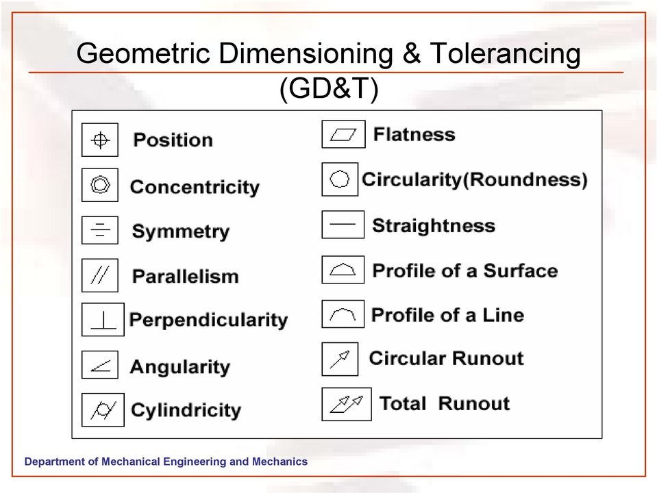
7 How are Tolerances Specified Size Limits specifying the allowed variation in each dimension (length, width, height, diameter, etc.) are given on the drawing Geometry Geometric Tolerancing Allows for specification of tolerance for the geometry of a part separate from its size GDT (Geometric Dimensioning and Tolerancing) uses special symbols to control different geometric features of a part
")
8 Value of Tolerance The tolerance for a single dimension may be specified with the dimension and then the tolerance. The tolerance is total variation between the upper and lower limits.

9 General Tolerances These are specified when all dimension in the drawings have the same tolerance. These notes are used to reduce the number of dimensions required on a drawing and to promote drawing clarity. 1 2

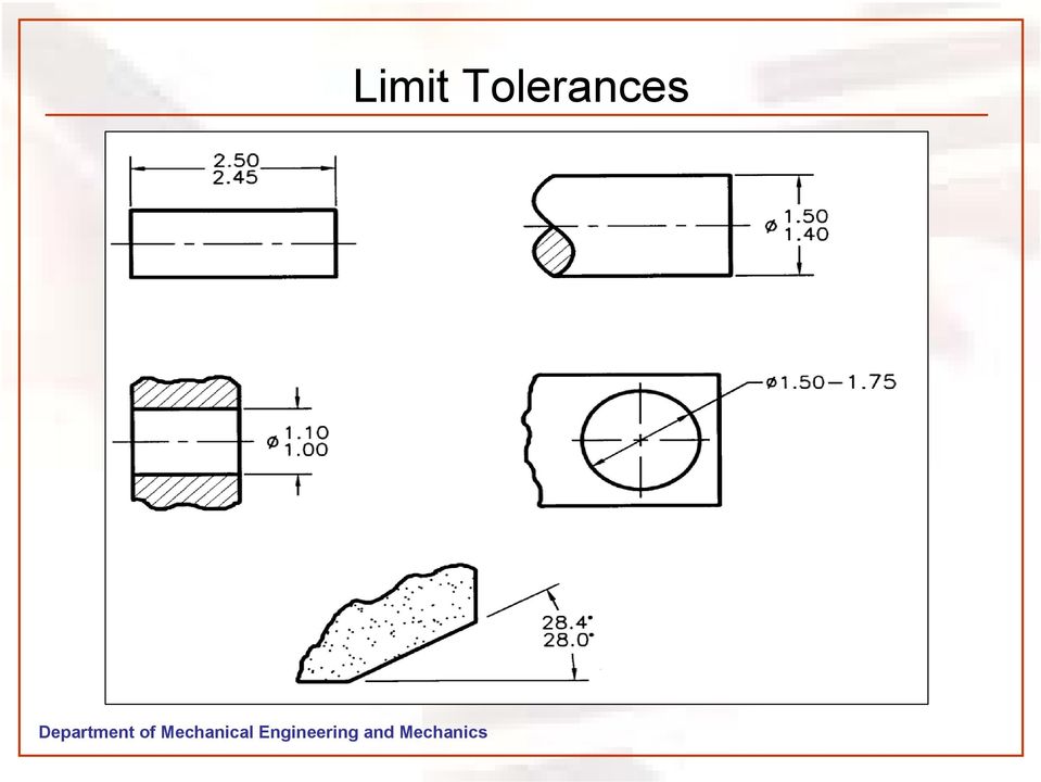
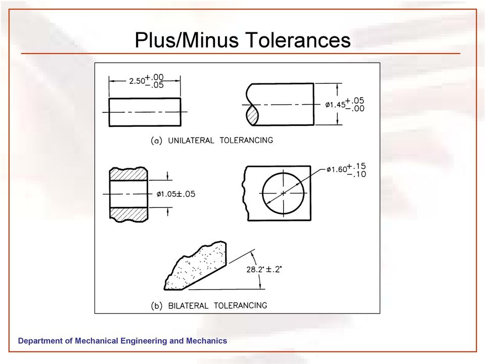
10 Tolerances specified for size Limit Tolerances (12.75/12.25 ) Plus/Minus Tolerances Unilateral Tolerances - ( or - xxx) Bilateral Tolerances - ( xxx/- xxx) These tolerance values indicate the: MMC: Maximum Material Condition LMC: Least Material Condition
 These tolerance values indicate the: MMC: Maximum")
11 Limit Tolerances MMC: Maximum Material Condition LMC: Least Material Condition

12 Limit Tolerances
13 Plus/Minus Tolerances
14 Allowance and Clearance ALLOWANCE Allowance is defined as an intentional difference between the maximum material limits of mating parts. Allowance is the minimum clearance (positive allowance), or maximum interference (negative allowance) between mating parts. The calculation formula for allowance is: ALLOWANCE = MMC HOLE MMC SHAFT CLEARANCE Clearance is defined as the loosest fit or maximum intended difference between mating parts. The calculation formula for clearance is: CLEARANCE = LMC HOLE LMC SHAFT

15 Types of Fit Types of Fit Clearance fit The parts are toleranced such that the largest shaft is smaller than the smallest hole The allowance is positive and greater than zero Interference fit The max. clearance is always negative The parts must always be forced together Transition fit The parts are toleranced such that the allowance is negative and the max. clearance is positive The parts may be loose or forced together

16 Standard ANSI Fits: BASIC FITS OF MATING PARTS Running and Sliding fits (RC) are intended to provide a running performance with suitable lubrication allowance. The range is from RC1 to RC9. Force fits (FN) or Shrink fits constitute a special type of interference fit characterized by maintenance of constant pressure. The range is from FN1 to FN5. A force fit is referred to as interference fit or a shrink fit. The smallest amount of interference is: MIN INTERFERENCE = LMC SHAFT - LMC HOLE The greatest amount of interference is: MAX INTERFERENCE = MMC SHAFT - MMC HOLE Locational fits are intended to determine only the location of the mating parts.

17 Sample Calculation Given: Diameter of shaft: 1.5mm Upper Limit Tolerance: 0.03mm Lower Limit Tolerance : 0.04mm Given: Diameter of Hole: 1.48mm Upper Limit Tolerance : 0.03mm Lower Limit Tolerance : 0.05mm Allowance: MMC-Hole - MMC-Shaft = = - 0.1mm Clearance: LMC-Hole LMC-Shaft = = 0.05mm Answer Allowance: -0.1mm Clearance: 0.05mm Type of Fit: Transition Fit

18 Geometric Dimensioning & Tolerancing (GD&T)
19 Tolerance of Form Straightness Straightness Tolerance Zone Straightness Tolerance

20 Tolerance of Form FLATNESS Note: 0.16 < 0.5 (size tolerance)

21 Tolerance of Form Circularity Circularity Tolerance Zone Circularity Tolerance
22 Tolerance of Form Cylindricity Cylindricity Tolerance Zone Cylindricity Tolerance
23 Tolerance of Orientation Perpendicularity Perpendicularity Tolerance Zone Perpendicularity Tolerance
24 Parallelism Tolerance of Orientation Parallelism Tolerance Zone T: Tangent Plane Parallelism Tolerance
25 Tolerances in AutoCAD
26 Tolerances in AutoCAD
27 Tolerances in AutoCAD
28 GEOMETRY DIMESIONING AND TOLERANCE FOR CADD/CAM Some dimensioning and tolerance guidelines for use in conjunction with CADD/CAM: Geometry tolerancing is necessary to control specific geometric form and location. Major features of the part should be used to establish the basic coordinate system, but are not necessary defined as datum. Subcoordinated systems that are related to the major coordinates are used to locate and orient features on a part. Define part features in relation to three mutually perpendicular reference plans, and along features that are parallel to the motion of CAM equipment. Establish datum related to the function of the part, and relate datum features in order of precedence as a basis for CAM usage. Completely and accurately dimension geometric shapes. Regular geometric shapes may be defined by mathematical formulas. A profile feature that is defined with mathematical formulas should not have coordinate dimensions unless required for inspection or reference. Coordinate or tabular dimensions should be used to identify approximate dimensions on an arbitrary profile. Use the same type of coordinate dimensioning system on the entire drawing. Continuity of profile is necessary for CADD. Clearly define contour changes at the change or point of tangency. Define at least four points along an irregular profile. Circular hole patterns may be defined with polar coordinate dimensioning. When possible, dimension angles in degrees and decimal parts of degrees. Base dimensions at the mean of a tolerance because the computer numerical control (CNC) programmer normally splits a tolerance and works to the mean. While this is theoretically desirable, one can not predict where the part will be made. Dimensions should always be based on design requirements. If it is known that a part will be produced always by CNC methods, then establish dimensions without limits that conform to CNC machine capabilities. Bilateral profile tolerances are also recommended for the same reason.
29 Further Reading Interpretation of Geometric Dimensioning & Tolerancing by Daniel E. Puncochar Geometric Dimensioning and Tolerancing by Alex Krulikowski Geo-Metrics III : The Application of Geometric Dimensioning and Tolerancing Techniques (Using the Customary Inch Systems) by Lowell W. Foster Tolerance design : a handbook for developing optimal specifications by C.M. Creveling. Dimensioning and Tolerancing Handbook by Paul J. Drake Inspection and Gaging by Clifford W. Kennedy Geometric Dimensioning and Tolerancing by Cecil H. Jensen Tolerance Stack-Up Analysis by James D. Meadows
30 Home Work #2 1. Find T H, T s, Allowance, C max, C min, and what kind of fit it is? Hole F 66 upper deviation , lower deviation 0.0 Shaft F 66 upper deviation , lower deviation Find T H, T s, Allowance, C max, I max, and what kind of fit it is? Hole F 32 upper deviation , lower deviation 0.0 Shaft F 32 upper deviation , lower deviation If a shaft is 10±0.05 inch what is its maximum and least material conditions. 4. Please draw circularity and perpendicularity symbol blocks with geometric tolerance of for each, and sketch their tolerance zones for a cylinder and a upside down T shape block respectively.
31 Home Work #2 contd.. T h = tolerance of hole T s = Tolerance of shaft C max = Maximum clearance C min = Minimum clearance I max = Maxiumum interference F66 and F32 indicates the nominal dimensions of the hole or shaft Refer Notes and AutoCAD text book for help in solving problems. Home works should include your names and the section you belong to. Will be due during the next Lecture Class.
Section. Tolerances. Aluminum Extrusion Manual. 4th Edition
 Section 8 Tolerances Aluminum Extrusion Manual 4th Edition Section 8 How straight is straight enough? How flat is flat enough? How uniform must a wall thickness be in order to be acceptable? These are
ASME Geometric Dimensioning and Tolerancing Professional Certification
 ASME Geometric Dimensioning and Tolerancing Professional Certification Applicant Information STATEMENT OF POLICY ON THE USE OF ASME GDTP SYMBOLS AND AUTHORIZATION IN ADVERTISING ASME has established procedures
AC 2012-4265: PROMOTING AWARENESS IN MANUFACTURING STU- DENTS OF
 AC 2012-4265: PROMOTING AWARENESS IN MANUFACTURING STU- DENTS OF Dr. Merwan B. Mehta, East Carolina University Merwan Mehta, Ph.D., is Associate Professor at East Carolina University, Greenville, N.C.,
Brown Hills College of Engineering & Technology Machine Design - 1. UNIT 1 D e s i g n P h i l o s o p h y
 UNIT 1 D e s i g n P h i l o s o p h y Problem Identification- Problem Statement, Specifications, Constraints, Feasibility Study-Technical Feasibility, Economic & Financial Feasibility, Social & Environmental
Engineering & Design: Geometric Dimensioning
 Section Contents NADCA No. Format Page 1 Introduction -2 S E C T I O N 2 What is GD&T? -2 3 Why Should GD&T be Used? -3 4 Datum Reference Frame -4 4.1 Primary, Secondary, Tertiary Features & Datums -4
An Overview of ASME Y14.41 2003
 An Overview of ASME Y14.41 2003 August 5, 2003 Alex Krulikowski 1 Introduction Alex Krulikowski Manager of Standards and GD&T COE Embedded GD&T implementation project at GM Powertrain Chair of ASME Y14.41
DRAFTING MANUAL. Gears (Bevel and Hypoid) Drafting Practice
 Drafting Practice") Page 1 1.0 General This section provides the basis for uniformity in engineering gears drawings and their technical data for gears with intersecting axes (bevel gears), and nonparallel, nonintersecting
Page 1 1.0 General This section provides the basis for uniformity in engineering gears drawings and their technical data for gears with intersecting axes (bevel gears), and nonparallel, nonintersecting
CATIA Functional Tolerancing & Annotation TABLE OF CONTENTS
 TABLE OF CONTENTS Introduction...1 Functional Tolerancing and Annotation...2 Pull-down Menus...3 Insert...3 Functional Tolerancing and Annotation Workbench...4 Bottom Toolbar Changes...5 3D Grid Toolbar...5
SolidWorks TolAnalyst Frequently Asked Questions
 SolidWorks TolAnalyst Frequently Asked Questions Q: What is tolerance stack-up analysis? A: A Tolerance Stack-Up Analysis is an analysis used by designers and engineers to determine if an assembly of parts
Product Design (Part 4)
") Product Design (Part 4) Engineering Drawing Chapter 16 Drawing Standards Line conventions and lettering- ANSI/ASME Y14.2M-1992 Multiview and sectional view drawings- ANSI/ASME Y14.3M-1994 Pictorial drawing-ansi/asme
Product Design (Part 4) Engineering Drawing Chapter 16 Drawing Standards Line conventions and lettering- ANSI/ASME Y14.2M-1992 Multiview and sectional view drawings- ANSI/ASME Y14.3M-1994 Pictorial drawing-ansi/asme
Working Drawing and Assemblies. Chapter 10
 Working Drawing and Assemblies Chapter 10 Objectives 1.Define working drawings. 2. Describe how working drawings are used in industry. 3. List the major components of a complete set of working drawings.
ISO 1101 Geometrical product specifications (GPS) Geometrical tolerancing Tolerances of form, orientation, location and run-out
 Geometrical tolerancing Tolerances of form, orientation, location and run-out") INTERNATIONAL STANDARD ISO 1101 Third edition 2012-04-15 Geometrical product specifications (GPS) Geometrical tolerancing Tolerances of form, orientation, location and run-out Spécification géométrique
INTERNATIONAL STANDARD ISO 1101 Third edition 2012-04-15 Geometrical product specifications (GPS) Geometrical tolerancing Tolerances of form, orientation, location and run-out Spécification géométrique
Precision Manufacturing Regional Alliance Project (PMRAP) Accelerated Weekend Program. Springfield Technical Community College.
 Accelerated Weekend Program. Springfield Technical Community College.") Precision Manufacturing Regional Alliance Project (PMRAP) Accelerated Weekend Program At Springfield Technical Community College Summary Report Precision Manufacturing Regional Alliance Project (PMRAP)
Precision Manufacturing Regional Alliance Project (PMRAP) Accelerated Weekend Program At Springfield Technical Community College Summary Report Precision Manufacturing Regional Alliance Project (PMRAP)
Technical Regulations 2015-2016
 F1 in Schools - 2014 World Finals Technical Regulations Technical Regulations 2015-2016 2013 - F1 in Schools Ltd. Page 1 of 27 3 September 2015 CONTENTS PREFACE SUMMARY OF MAIN REVISIONS FROM 2013 REGULATIONS...
Removing chips is a method for producing plastic threads of small diameters and high batches, which cause frequent failures of thread punches.
 Plastic Threads Technical University of Gabrovo Yordanka Atanasova Threads in plastic products can be produced in three ways: a) by direct moulding with thread punch or die; b) by placing a threaded metal
Introduction to CATIA V5
 Introduction to CATIA V5 Release 16 (A Hands-On Tutorial Approach) Kirstie Plantenberg University of Detroit Mercy SDC PUBLICATIONS Schroff Development Corporation www.schroff.com www.schroff-europe.com
ABERLINK 3D MKIII MEASUREMENT SOFTWARE
 ABERLINK 3D MKIII MEASUREMENT SOFTWARE PART 1 (MANUAL VERSION) COURSE TRAINING NOTES ABERLINK LTD. EASTCOMBE GLOS. GL6 7DY UK INDEX 1.0 Introduction to CMM measurement...4 2.0 Preparation and general hints
Screw Thread Design. Rev. 3-4-09
 Screw Thread Design Screw Thread Fundamentals A screw thread is defined as a ridge of uniform section in the form of a helix on either the external or internal surface of a cylinder. Internal threads refer
Precision Manufacturing Program
 Precision Manufacturing Program Conventional Precision Manufacturing (CPM) Certificate Program During this program, students learn about subjects that form a solid foundation for a career in manufacturing.
Making 3D Threads in Feature Based Solid Modelers
 Making 3D Threads in Feature Based Solid Modelers THREAD BASICS Making true geometric threads in feature-based solid modelers is a fairly straightforward process and can be handled using several different
F1 in Schools - 2014 World Finals Technical Regulations. 2014 WORLD FINALS Technical Regulations
 2014 WORLD FINALS Technical Regulations Refer also to the 2014 World Finals Competition Regulations. For World Finals use only. 2013 - F1 in Schools Ltd. Page 1 of 23 13 August 2014 Front Cover A1 Racing
Parametric Technology Corporation. Pro/ENGINEER Wildfire 4.0 Tolerance Analysis Extension Powered by CETOL Technology Reference Guide
 Parametric Technology Corporation Pro/ENGINEER Wildfire 4.0 Tolerance Analysis Extension Powered by CETOL Technology Reference Guide Copyright 2007 Parametric Technology Corporation. All Rights Reserved.
West Sound Technical Skills Center 101 National Avenue N. Bremerton WA 98312
 West Sound Technical Skills Center 101 National Avenue N. Bremerton WA 98312 Instructor: Tony Sharpe Phone: 360-473-0585 Fax: 360-478-5090 Email: [email protected] Hours: 7:30 a.m. 3:00
CATIA Wireframe & Surfaces TABLE OF CONTENTS
 TABLE OF CONTENTS Introduction... 1 Wireframe & Surfaces... 2 Pull Down Menus... 3 Edit... 3 Insert... 4 Tools... 6 Generative Shape Design Workbench... 7 Bottom Toolbar... 9 Tools... 9 Analysis... 10
Selecting the Best Approach to Teach 3D Modeling to Technical College Engineering
 Paper ID #12358 Selecting the Best Approach to Teach 3D Modeling to Technical College Engineering Students Dr. Farzin Heidari, Texas A&M University, Kingsville c American Society for Engineering Education,
Mechanical Measurement and Inspection Techniques
 Unit 19: Mechanical Measurement and Inspection Techniques Unit code: QCF Level 3: Credit value: 10 Guided learning hours: 60 Aim and purpose J/600/0269 BTEC National This unit will give learners a broad
SAMPLE TEST PAPER - I
 SCHEME E SAMPLE TEST PAPER - I Course Name : Mechanical Engineering Group Course Code : AE/PG/PT/ME/MH/FE Semester : Third Subject : Mechanical Engineering Drawing 12042 Time : 90 Minutes Marks: 25 Instruction:
Standards for Working Drawings
 Standards for Working Drawings 27 August 2013 Department of Mechanical and Mechatronic Engineering and Sustainable Manufacturing California State University, Chico Chico, California 95929-0789 Contents
Manufacturing Technology
 Job Ready Assessment Blueprint Manufacturing Technology Test Code: 2084 / Version: 01 Copyright 2007. All Rights Reserved. General Assessment Information Blueprint Contents General Assessment Information
Technical Data. 7. Bearing Fits. 7.1 Interference. 7.2 Calculation of interference F B LLLLLLLLL( A-54
 Technical Data 7. Bearing Fits 7.1 Interference For rolling s the rings are fixed on the or in the housing so that slip or movement does not occur between the mated surface during operation or under. This
GCSE Revision Notes Mathematics. Volume and Cylinders
 GCSE Revision Notes Mathematics Volume and Cylinders irevise.com 2014. All revision notes have been produced by mockness ltd for irevise.com. Email: [email protected] Copyrighted material. All rights reserved;
F1 in Schools - 2015 World Finals Technical Regulations
 2013 - F1 in Schools Ltd. Page 1 of 24 25 March 2015 Front Cover Colossus F1 2014 World Champions F1 Car, Robert May's School, Hampshire, England Amendments made on [Date] are indicated thus (using red
What s New in the ASME Y14.5 2009 Standard!
 What s New in the ASME Y14.5 2009 Standard! 2009-07-31 Bill Tandler With editorial contributions from Evan Janeshewski and Ron Grube Multi Metrics & SmartGD&T 1. Introduction In March 2009 the ASME has
Geometric Optics Converging Lenses and Mirrors Physics Lab IV
 Objective Geometric Optics Converging Lenses and Mirrors Physics Lab IV In this set of lab exercises, the basic properties geometric optics concerning converging lenses and mirrors will be explored. The
GEAROLOGY 2-1 SPUR GEARS SPUR GEARS
 GEAROLOGY 2-1 2 2-2 GEAROLOGY COMMON APPLICATIONS: Spur gears are used to Now that you ve been introduced to both Boston Gear and some of the basics of our Gearology course which we like to call Power
MATHEMATICS FOR ENGINEERING BASIC ALGEBRA
 MATHEMATICS FOR ENGINEERING BASIC ALGEBRA TUTORIAL 4 AREAS AND VOLUMES This is the one of a series of basic tutorials in mathematics aimed at beginners or anyone wanting to refresh themselves on fundamentals.
Technical Drawing. MEC1000 Spring 2006 Instructor: David Anderson
 Technical Drawing MEC1000 Spring 2006 Instructor: David Anderson Topics Drawing Views Drawing Standards Best Practices Creating Drawings in SolidWorks Spring 2006 MEC1000 Technical Drawing - D. Anderson
Grade 8 Mathematics Geometry: Lesson 2
 Grade 8 Mathematics Geometry: Lesson 2 Read aloud to the students the material that is printed in boldface type inside the boxes. Information in regular type inside the boxes and all information outside
1. Kyle stacks 30 sheets of paper as shown to the right. Each sheet weighs about 5 g. How can you find the weight of the whole stack?
 Prisms and Cylinders Answer Key Vocabulary: cylinder, height (of a cylinder or prism), prism, volume Prior Knowledge Questions (Do these BEFORE using the Gizmo.) [Note: The purpose of these questions is
CATIA Drafting TABLE OF CONTENTS
 TABLE OF CONTENTS Introduction...1 Drafting...2 Drawing Screen...3 Pull-down Menus...4 File...4 Edit...5 View...6 Insert...7 Tools...8 Drafting Workbench...9 Views and Sheets...9 Dimensions and Annotations...10
Traditional Drawing Tools
 Engineering Drawing Traditional Drawing Tools DRAWING TOOLS DRAWING TOOLS 1. T-Square 2. Triangles DRAWING TOOLS HB for thick line 2H for thin line 3. Adhesive Tape 4. Pencils DRAWING TOOLS 5. Sandpaper
IMPLEMENTATION OF MS ACCESS SOFTWARE FOR CASING-CLASS MANUFACTURING FEATURES SAVING
 constructional data, database, casing-class part, MS Access Arkadiusz GOLA *, Łukasz SOBASZEK ** IMPLEMENTATION OF MS ACCESS SOFTWARE FOR CASING-CLASS MANUFACTURING FEATURES SAVING Abstract Manufacturing
Quality Concepts. 1.1 Introduction. 1.2 Quality and Reliability Defined
 1 Quality Concepts 1.1 Introduction Quality is perceived differently by different people. Yet, everyone understands what is meant by quality. In a manufactured product, the customer as a user recognizes
PARAMETRIC MODELING. David Rosen. December 1997. By carefully laying-out datums and geometry, then constraining them with dimensions and constraints,
 1 of 5 11/18/2004 6:24 PM PARAMETRIC MODELING David Rosen December 1997 The term parametric modeling denotes the use of parameters to control the dimensions and shape of CAD models. Think of a rubber CAD
In mathematics, there are four attainment targets: using and applying mathematics; number and algebra; shape, space and measures, and handling data.
 MATHEMATICS: THE LEVEL DESCRIPTIONS In mathematics, there are four attainment targets: using and applying mathematics; number and algebra; shape, space and measures, and handling data. Attainment target
16 Circles and Cylinders
 16 Circles and Cylinders 16.1 Introduction to Circles In this section we consider the circle, looking at drawing circles and at the lines that split circles into different parts. A chord joins any two
Geometry and dimensional tolerances of engine bearings
 Geometry and dimensional tolerances of engine bearings Dr. Dmitri Kopeliovich (Research & Development Manager.) 1. Hydrodynamic lubrication Engine bearings operate mostly in the hydrodynamic regime of
CHAPTER 8, GEOMETRY. 4. A circular cylinder has a circumference of 33 in. Use 22 as the approximate value of π and find the radius of this cylinder.
 TEST A CHAPTER 8, GEOMETRY 1. A rectangular plot of ground is to be enclosed with 180 yd of fencing. If the plot is twice as long as it is wide, what are its dimensions? 2. A 4 cm by 6 cm rectangle has
7.3 Fit selection. Inner ring: Rotating. Outer ring: Stationary. Inner ring: Stationary. Outer ring: Rotating. Inner ring: Stationary
 7. Bearing Fits 7. Fitting For rolling s, inner and outer rings are fixed on the or in the housing so that relative movement does not occur between fitting surfaces during operation or under. This relative
Dŵr y Felin Comprehensive School. Perimeter, Area and Volume Methodology Booklet
 Dŵr y Felin Comprehensive School Perimeter, Area and Volume Methodology Booklet Perimeter, Area & Volume Perimeters, Area & Volume are key concepts within the Shape & Space aspect of Mathematics. Pupils
Quick Reference ebook
 This file is distributed FREE OF CHARGE by the publisher Quick Reference Handbooks and the author. Quick Reference ebook Click on Contents or Index in the left panel to locate a topic. The math facts listed
Mathematics (Project Maths Phase 1)
") 2012. M128 S Coimisiún na Scrúduithe Stáit State Examinations Commission Leaving Certificate Examination, 2012 Sample Paper Mathematics (Project Maths Phase 1) Paper 2 Ordinary Level Time: 2 hours, 30
2012. M128 S Coimisiún na Scrúduithe Stáit State Examinations Commission Leaving Certificate Examination, 2012 Sample Paper Mathematics (Project Maths Phase 1) Paper 2 Ordinary Level Time: 2 hours, 30
Charlesworth School Year Group Maths Targets
 Charlesworth School Year Group Maths Targets Year One Maths Target Sheet Key Statement KS1 Maths Targets (Expected) These skills must be secure to move beyond expected. I can compare, describe and solve
NEW MEXICO Grade 6 MATHEMATICS STANDARDS
 PROCESS STANDARDS To help New Mexico students achieve the Content Standards enumerated below, teachers are encouraged to base instruction on the following Process Standards: Problem Solving Build new mathematical
F1 in Schools - 2015 World Finals Technical Regulations. Formula 1 Class
 F1 in Schools - 2015 World Finals Technical Regulations Formula 1 Class 2013 - F1 in Schools Ltd. Page 1 of 23 7 July 2015 Front Cover Colossus F1 2014 World Champions F1 Car, Robert May's School, Hampshire,
Engineering & Design: Coordinate Dimensioning
 s e c t i o n Section Contents NADCA No. Format Page Frequently Asked Questions (FAQ) -2 1 Introduction -2 2 Section Objectives -3 3 Standard and Precision Tolerances -3 4 Production Part Technologies
CAD Techniques Helping To Enhance NDT Workflow
 CAD Techniques Helping To Enhance NDT Workflow Steve McCarley Eclipse Sientific Products Inc. www.eclipsescientific.com This document will show you some applied techniques and uses of CAD to solve some
Calculate the circumference of a circle with radius 5 cm. Calculate the area of a circle with diameter 20 cm.
 RERTIES F CIRCLE Revision. The terms Diameter, Radius, Circumference, rea of a circle should be revised along with the revision of circumference and area. Some straightforward examples should be gone over
Modeling Curved Surfaces
 Modeling Cylindrical and Curved Theory Views of Cylinders Contour Lines Extruded Surfaces Revolved Surfaces & Cutouts Profile Shape Axis of Revolution Swept Surfaces & Cutouts Profile Shape Path Curves
Force measurement. Forces VECTORIAL ISSUES ACTION ET RÉACTION ISOSTATISM
 Force measurement Forces VECTORIAL ISSUES In classical mechanics, a force is defined as "an action capable of modifying the quantity of movement of a material point". Therefore, a force has the attributes
Home"" """"> ar.cn.de.en.es.fr.id.it.ph.po.ru.sw
 Home"" """"> ar.cn.de.en.es.fr.id.it.ph.po.ru.sw Milling of Grooves, Elongated Slots and Break-throughs - Course: Techniques for machining of material. Trainees' handbook of lessons (Institut fr Berufliche
Area of Parallelograms, Triangles, and Trapezoids (pages 314 318)
") Area of Parallelograms, Triangles, and Trapezoids (pages 34 38) Any side of a parallelogram or triangle can be used as a base. The altitude of a parallelogram is a line segment perpendicular to the base
Area of Parallelograms, Triangles, and Trapezoids (pages 34 38) Any side of a parallelogram or triangle can be used as a base. The altitude of a parallelogram is a line segment perpendicular to the base
Splined connections with involute splines based on reference diameters Part 1: Principles
 March 2006 DIN 5480-1 Splined connections with involute splines based on reference diameters Part 1: Principles Passverzahnungen mit Evolventenflanken und Bezugsdurchmesser Teil 1: Grundlagen Supersedes
ELECTRIC FIELD LINES AND EQUIPOTENTIAL SURFACES
 ELECTRIC FIELD LINES AND EQUIPOTENTIAL SURFACES The purpose of this lab session is to experimentally investigate the relation between electric field lines of force and equipotential surfaces in two dimensions.
INTERNATIONAL HOCKEY FEDERATION PERFORMANCE REQUIREMENTS AND TEST PROCEDURES FOR HOCKEY BALLS. Published: April 1999
 INTERNATIONAL HOCKEY FEDERATION PERFORMANCE REQUIREMENTS AND TEST PROCEDURES FOR HOCKEY BALLS Published: April 1999 CONTENTS 1 Introduction 2 Test Procedures General 3 Standards and Specific Test Procedures
MET 306. Activity 8a. Mechanism Design Creo 2.0 Level 7 POINT A GROUND LINK LINK 1 LINK 2 LINK 3 POINT B 10/15/2010 1
 Mechanism Design Creo 2.0 Level 7 POINT A LINK 1 GROUND LINK LINK 2 LINK 3 POINT B 10/15/2010 1 Download parts ground, key, link_1, link_2, link_3 and pulley from the V:/MET_306/Activity_8_Creo drive.
Gear Reference Guide
 W.M. Berg manufactures several styles of gears. Each gear has and serves its own particular application. Listed below are brief descriptions and application notes for the variety of available styles. Further
Holes & Selective Laser Sintering
 SLS is one of the most accurate 3D printing processes. The process has a layer thickness of 0.1mm. This is the thickness with which a new layer is added to each part. In any direction therefore the maximum
1. A plane passes through the apex (top point) of a cone and then through its base. What geometric figure will be formed from this intersection?
 of a cone and then through its base. What geometric figure will be formed from this intersection?") Student Name: Teacher: Date: District: Description: Miami-Dade County Public Schools Geometry Topic 7: 3-Dimensional Shapes 1. A plane passes through the apex (top point) of a cone and then through its
Student Name: Teacher: Date: District: Description: Miami-Dade County Public Schools Geometry Topic 7: 3-Dimensional Shapes 1. A plane passes through the apex (top point) of a cone and then through its
GEAROLOGY 4-1 WORMS AND WORM GEARS WORMS AND WORM GEARS
 GEAROLOGY 4-1 4 4-2 GEAROLOGY COMMON APPLICATIONS: Worm and worm gear sets are used in many, everyday products including: electrical mixers, hubometers, right Now that you have an understanding of two
Three Channel Optical Incremental Encoder Modules Technical Data
 Three Channel Optical Incremental Encoder Modules Technical Data HEDS-9040 HEDS-9140 Features Two Channel Quadrature Output with Index Pulse Resolution Up to 2000 CPR Counts Per Revolution Low Cost Easy
Characteristics of the Four Main Geometrical Figures
 Math 40 9.7 & 9.8: The Big Four Square, Rectangle, Triangle, Circle Pre Algebra We will be focusing our attention on the formulas for the area and perimeter of a square, rectangle, triangle, and a circle.
OD1641 PRINCIPLES OF DRAFTING AND SHOP DRAWINGS
 SUBCOURSE OD1641 EDITION 8 PRINCIPLES OF DRAFTING AND SHOP DRAWINGS US ARMY REPAIR SHOP TECHNICIAN WARRANT OFFICER ADVANCED CORRESPONDENCE COURSE MOS/SKILL LEVEL: 441A PRINCIPLES OF DRAFTING AND SHOP
Developing Conceptual Understanding of Number. Set J: Perimeter and Area
 Developing Conceptual Understanding of Number Set J: Perimeter and Area Carole Bilyk [email protected] Wayne Watt [email protected] Perimeter and Area Vocabulary perimeter area centimetres right angle Notes
Pennsylvania System of School Assessment
 Pennsylvania System of School Assessment The Assessment Anchors, as defined by the Eligible Content, are organized into cohesive blueprints, each structured with a common labeling system that can be read
DEUTSCHE NORM June 1998. Forms and dimensions of undercuts
 DEUTSCHE NORM June 1998 Forms dimensions of s { 509 ICS 01.100.20; 25.020 Descriptors: Undercuts, types, dimensions, technical drawings. Supersedes August 1966 edition. Freistiche Formen, Maße In keeping
EJOT Spiralform. The thread formers for metal. EJOT The Quality Connection
 EJOT Spiralform The thread formers for metal EJOT The Quality Connection Imprint Editor: EJOT GmbH & Co. KG Industrial Fasteners Division D 57319 Bad Berleburg Layout and Realisation: EJOT GmbH & Co. KG
Solid Mechanics. Stress. What you ll learn: Motivation
 Solid Mechanics Stress What you ll learn: What is stress? Why stress is important? What are normal and shear stresses? What is strain? Hooke s law (relationship between stress and strain) Stress strain
Autodesk Fusion 360: Assemblies. Overview
 Overview In this module you will learn how different components can be put together to create an assembly. We will use several tools in Fusion 360 to make sure that these assemblies are constrained appropriately
Radius Compensation G40, G41, & G42 (cutter radius compensation for machining centers, tool nose radius compensation for turning centers)
") Radius Compensation G40, G41, & G42 (cutter radius compensation for machining centers, tool nose radius compensation for turning centers) These features are commonly well covered in most basic CNC courses.
Radius Compensation G40, G41, & G42 (cutter radius compensation for machining centers, tool nose radius compensation for turning centers) These features are commonly well covered in most basic CNC courses.
CAD / CAM Dr. P. V. Madhusuthan Rao Department of Mechanical Engineering Indian Institute of Technology, Delhi Lecture No. # 12 Reverse Engineering
 CAD / CAM Dr. P. V. Madhusuthan Rao Department of Mechanical Engineering Indian Institute of Technology, Delhi Lecture No. # 12 Reverse Engineering So what we will do in today s lecture is basically take
Stainless Linear Motion Rolling Guide series
 products are avaiable from: MARYLAND METRICS phones: (410)358-3130 (800)638-1830 faxes: (410)358-3142 (800)872-9329 P.O.Box 261 Owings Mills, MD 21117 USA URL: http://mdmetric.com E-mail: [email protected]
Special Rolling Bearings
 Special Rolling Bearings Special Rolling Bearings KINEX produces, except a large number of types and sizes of standardized rolling bearings of both basic and modified designs presented in the preceding
Pro/ENGINEER Wildfire 5.0 Introduction to Surface Modeling
 Introduction Several advanced surface types are available as listed below. Variable Section Sweep Boundary Blend Section to Surfaces Blend Surface to Surface Blend A surface is created by sweeping a single
SpaceClaim Introduction Training Session. A SpaceClaim Support Document
 SpaceClaim Introduction Training Session A SpaceClaim Support Document In this class we will walk through the basic tools used to create and modify models in SpaceClaim. Introduction We will focus on:
THRUST NEEDLE ROLLER AND CAGE ASSEMBLIES Assembly Dimensions, Load Ratings, Thrust Washer and Piloting Dimensions... 480-487
 Thrust Bearings Page Nomenclature............................................ 474 Introduction............................................. 476 Identification.............................................
Measurement Tools in Inventor
 WP-MFG-00232 September 2012 David Gate Measurement Tools in Inventor A summary of the measurement tools within Inventor and showing some of their many uses. All Inventor Users The Measurement Tools within
Activity Set 4. Trainer Guide
 Geometry and Measurement of Solid Figures Activity Set 4 Trainer Guide Mid_SGe_04_TG Copyright by the McGraw-Hill Companies McGraw-Hill Professional Development GEOMETRY AND MEASUREMENT OF SOLID FIGURES
Objectives. Experimentally determine the yield strength, tensile strength, and modules of elasticity and ductility of given materials.
 Lab 3 Tension Test Objectives Concepts Background Experimental Procedure Report Requirements Discussion Objectives Experimentally determine the yield strength, tensile strength, and modules of elasticity
The GED math test gives you a page of math formulas that
 Math Smart 643 The GED Math Formulas The GED math test gives you a page of math formulas that you can use on the test, but just seeing the formulas doesn t do you any good. The important thing is understanding
Designing and Drawing a Sprocket Visualizing ideas through the creation of CAD solid models is a key engineering skill.
 05 Webster St. Hanover Massachusetts 0339 Tel. 78 878 5 Fax 78 878 6708 Designing and Drawing a Sprocket Visualizing ideas through the creation of CAD solid models is a key engineering skill. The following
Algebra 1 2008. Academic Content Standards Grade Eight and Grade Nine Ohio. Grade Eight. Number, Number Sense and Operations Standard
 Academic Content Standards Grade Eight and Grade Nine Ohio Algebra 1 2008 Grade Eight STANDARDS Number, Number Sense and Operations Standard Number and Number Systems 1. Use scientific notation to express
PCB Design Perfection Starts in the Cad Library Part 1 The 1608 (Eia 0603) Chip Component
 Chip Component") PCB Design Perfection Starts in the Cad Library Part 1 The 1608 (Eia 0603) Chip Component Tom Hausherr EDA Library Product Manager Mentor Graphics Corp. [email protected] ABSTRACT The CAD library
PCB Design Perfection Starts in the Cad Library Part 1 The 1608 (Eia 0603) Chip Component Tom Hausherr EDA Library Product Manager Mentor Graphics Corp. [email protected] ABSTRACT The CAD library
CAD/ CAM Prof. P. V. Madhusudhan Rao Department of Mechanical Engineering Indian Institute of Technology, Delhi Lecture No. # 03 What is CAD/ CAM
 CAD/ CAM Prof. P. V. Madhusudhan Rao Department of Mechanical Engineering Indian Institute of Technology, Delhi Lecture No. # 03 What is CAD/ CAM Now this lecture is in a way we can say an introduction
Helical Gears K HG 1-20 R. Table of Contents. Catalog Number of KHK Stock Gears. Helical Gears. (Example) Direction of Helix (R) No.
 Direction of Helix (R) No.") Table of Contents Special Characteristics, Points of Caution in Selecting and Using... page 130 KHG Ground... page 134 SH... page 144 Catalog Number of KHK Stock Gears The Catalog Number for KHK stock
Table of Contents Special Characteristics, Points of Caution in Selecting and Using... page 130 KHG Ground... page 134 SH... page 144 Catalog Number of KHK Stock Gears The Catalog Number for KHK stock
FAGOR CNC 8055 ia-mc Control
 FAGOR CNC 8055 ia-mc Control The Fagor 8055 i/a-mc CNC control combines value & reliability with a featured packed modular control. This control was built for the shop environment with a rugged keyboard
PHYSICS 111 HOMEWORK SOLUTION #9. April 5, 2013
 PHYSICS 111 HOMEWORK SOLUTION #9 April 5, 2013 0.1 A potter s wheel moves uniformly from rest to an angular speed of 0.16 rev/s in 33 s. Find its angular acceleration in radians per second per second.
Formulas for gear calculation external gears. Contents:
 Formulas for gear calculation external gears Contents: Relationship between the involute elements Determination of base tooth thickness from a known thickness and vice-versa. Cylindrical spur gears with
Chapter 8 Geometry We will discuss following concepts in this chapter.
 Mat College Mathematics Updated on Nov 5, 009 Chapter 8 Geometry We will discuss following concepts in this chapter. Two Dimensional Geometry: Straight lines (parallel and perpendicular), Rays, Angles
Tom Kalkman Quality Solutions Product Management. Variation Analysis Users Conference Call
 Tom Kalkman Quality Solutions Product Management Variation Analysis Users Conference Call Smarter decisions, better products. Agenda Introduction Tc 10 & 10.1 review and what s new in Tc 10.1.1 Functional