RIGOL. User s Guide. DSA800 Options and Accessories. Jan RIGOL Technologies, Inc.
|
|
|
- Lindsey Daniels
- 9 years ago
- Views:
Transcription
1 User s Guide Jan RIGOL Technologies, Inc.
2
3 Guaranty and Declaration Copyright 2012 RIGOL Technologies, Inc. All Rights Reserved. Trademark Information RIGOL is a registered trademark of RIGOL Technologies, Inc. Publication Number UMD Notices RIGOL products are protected by patent law in and outside of P.R.C. RIGOL reserves the right to modify or change parts of or all the specifications and pricing policies at company s sole decision. Information in this publication replaces all previously corresponding material. RIGOL shall not be liable for losses caused by either incidental or consequential in connection with the furnishing, use or performance of this manual as well as any information contained. Any part of this document is forbidden to be copied or photocopied or rearranged without prior written approval of RIGOL. Product Certification RIGOL guarantees this product conforms to the national and industrial standards in China. International standard conformance certification is in progress, e.g. ISO. Contact Us If you have any problem or requirement when using our products, please contact RIGOL Technologies, Inc. or your local distributors, or visit: I
4 Contents Guaranty and Declaration... I... 1 Standard Accessories... 2 EMI Filter and Quasi-Peak Detector... 3 VSWR Measurement Kit... 4 Advanced Measurement Kit GHz Tracking Generator USB-GPIB Interface Converter II
5 Options and accessories provided by DSA800 series spectrum analyzer are as shown in the table below. If needed, please contact RIGOL or the local distributors. This manual only introduces the functions of the main options. For the option with remark in the table below, refer to the dedicated manual. Description Order No. Model Standard Accessories Options Optional Accessories Optional Manuals (Hard Copy) Spectrum Analyzer, 9 khz to 1.5 GHz (with preamplifier) Quick Guide (Hard Copy) DSA815 QGD03X00 CDROM (User s Guide, Programming Guide) - Power Cord - EMI Filter & Quasi-Peak Detector Kit (for DSA815 only) DSA800-EMI VSWR Measurement Kit (for DSA815 only) DSA800-VSWR VSWR Bridge [1] VB1020 Advanced Measurement Kit (for DSA815 only) DSA800-AMK 1.5 GHz Tracking Generator (for DSA815 only) DSA800-TG RF Demo Kit (Transmitter) [1] TX1000 USB-GPIB Interface Converter USB-GPIB Rack Mount Kit [1] DSA800-RMSA DSA Accessories Package [1] includes: N-SMA Cable, BNC-BNC Cable, N-BNC Adapter, N-SMA Adapter, 75 Ω-50 Ω Adapter 2 Antennas (900 MHz/1.8 GHz), 2 Antennas (2.4 GHz) Quick Guide, Chinese & English User s Guide, Chinese User s Guide, English Programming Guide, Chinese Programming Guide, English DSA Utility Kit QGD03X00 UGD03000 UGD03100 PGD03000 PGD03100 Remark: [1] for more details, refer to the corresponding manual (included in the option package in CD or hard copy form, or download the manual from 1
6 Standard Accessories The following are the standard accessories. Power Cord Quick Guide Resource CD [1] Remark: [1] the User s Guide and Programming Guide are included in the resource CD. You can also order the hard copies. Note: images in this section are indicative only. The actual products you receive may differ. 2

7 EMI Filter and Quasi-Peak Detector DSA800-EMI option provides Quasi-Peak detector and EMI filter (200 Hz, 9 khz, 120 khz, -6 db bandwidth). Quasi-Peak detection is a weighted form of peak detection. For each data point, the detector detects the peaks within the specified time interval, weights the peaks detected using circuit with specified charge and discharge structures as well as the display time constant specified in the CISPR Publication 16 standards and display the result. By default, the instrument uses Gauss filter and will switch to EMI filter automatically if Quasi-Peak detector is selected. Press BW/Det at the front panel. Then, press Det Type to select Quasi-Peak detector. At this point, the instrument automatically changes the filter type to EMI and the Filter Type menu is grayed out and disabled. DSA800-EMI option is used in electromagnetic interference test. 3
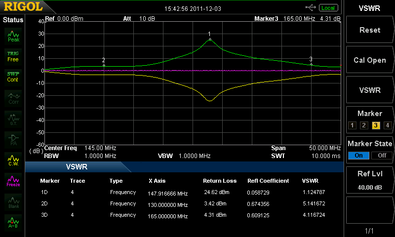
8 VSWR Measurement Kit DSA800-VSWR option (used together with the VB1020 and DSA800-TG options) provides measurement functions of S11-related specifications (such as the return loss, reflection coefficient and VSWR). VB1020 Device under Test Press Meas at the front panel and then press VSWR to enable the VSWR measurement function. The screen is divided into two windows with the upper window (the basic measurement window) displaying the sweep trace and the lower window displaying the measurement wizard and measurement results. Perform two measurements respectively according to the measurement wizard in the lower window: measurement with the device under test disconnected (Meas Setup Cal Open, represented by trace 2) and measurement with the device under test connected (Meas Setup VSWR, represented by trace 1). The return loss is determined by the difference (represented by the math trace) of the results of the two measurements and the reflection coefficient and VSWR are determined by the return loss. 4
9 5
10 Advanced Measurement Kit DSA800-AMK option provides various measurement functions, including T-Power, ACP (Adjacent Channel Power), Chan Pwr (Channel Power), OBW (Occupied Bandwidth), EBW (Emission Bandwidth), C/N Ratio, Harmo Dist (Harmonic Distortion) and TOI (Third Order Intermodulation). For advanced measurement functions, the measurement mode can be single or continuous and you can control the measurement including Restart, Pause and Resume. Press Meas at the front panel and then press Meas Fctn to select a measurement function. The screen is divided into two windows with the upper window (the basic measurement window) displaying the sweep trace and the lower window displaying the measurement results. 1. T-power The system enters zero span mode and calculates the power within the time domain. The types of powers available include Peak, Average and RMS. Start Line Stop Line Measurement Control Measurement Result Measurement Parameters 6
11 2. ACP Measure the powers of the main channel and adjacent channels as well as the power difference between the main channel and each of the adjacent channels. When this function is enabled, the span and resolution bandwidth of the analyzer are adjusted to smaller values automatically. Adjacent Channel Bandwidth Channel Spacing Main Channel Bandwidth 3. Chan Pwr Measure the power and power spectral density within the specified channel bandwidth. When this function is enabled, the span and resolution bandwidth are automatically adjusted to smaller values. 7
12 Integration Bandwidth Channel Power Span 4. OBW Integrate the power within the whole span and calculate the bandwidth occupied by this power according to the specified power ratio. The OBW function also indicates the difference between the center frequency of the channel under measurement and the center frequency of the analyzer. 8


13 5. EBW Measure the bandwidth between two points on the signal which are X db below the highest point within the span. 6. C/N Ratio Measure the powers of the carrier and noise with the specified bandwidths as well as their power ratio. Offset Frequency Noise Bandwidth Carrier Bandwidth 9

14 7. Harmo Dist Measure the power of each order of harmonic and THD (total harmonic distortion) of the carrier. The highest order of harmonic available is 10 and the fundamental wave amplitude must be greater than -50 dbm, or else the measurement will be invalid. 10
15 8. TOI Measure the parameters of the TOI production of two signals with the same amplitude and similar frequency. Those parameters include the frequencies and amplitudes of the Base Lower, Base Upper, 3rd Order Lower and 3rd Order Upper signal, as well as the Intercepts of both the Base Lower and Base Upper. 11
16 1.5 GHz Tracking Generator DSA800-TG option provides tracking output function. When the tracking generator is enabled, a signal with the same frequency of the current sweep signal is output from the [GEN OUTPUT 50 Ω] connector at the front panel and the power of the signal can be set through the menu. The tracking generator provides two working modes: Power Sweep output and Fixed Power output. When the tracking generator is used as an excitation, the DUT (device under test) characteristics can be obtained by measuring the output from the DUT. For example, use the tracking generator to verify the frequency response of the filter. Connect the filter to be tested to the [RF INPUT 50Ω] and [GEN OUTPUT 50Ω] connectors at the front panel of the spectrum analyzer. Filter 12
17 Measurement Example The figure below shows the frequency response of a 300 MHz low-pass filter. Tracking Generator Specifications Main Specifications Condition Value Frequency Range 9 khz to 1.5 GHz Output Power -20 dbm to 0 dbm, the step is 1 db Output Flatness 1 MHz to 1.5 GHz, referenced to 50 MHz ± 3 db 13

. USB powered instead of external power supply. Indicate the power status via a LED.")
18 USB-GPIB Interface Converter Through the RIGOL USB-GPIB interface converter, the spectrum analyzer can be connected to the GPIB bus controller of the PC, namely to expand a GPIB interface through which the spectrum analyzer can finish various tasks using the GPIB instructions more easily for the spectrum analyzer. The performance characteristics of the USB-GPIB interface converter are listed below. Achieve GPIB control via the USB Host interface of the spectrum analyzer. Distribute a GPIB address for the spectrum analyzer via the GPIB host device (PC). USB powered instead of external power supply. Indicate the power status via a LED. Connect the USB interface and the GPIB interface of the USB-GPIB interface converter to the USB Host interface of the spectrum analyzer and the GPIB bus controller of the PC respectively. LED Power Indicator PC GPIB USB Spectrum Analyzer 14
DSA800 Series Spectrum Analyzer
 DSA800 Series Spectrum Analyzer Configuration Guide This guide is used to help users to configure DSA800 series spectrum analyzer according to their requirements. You can get an overall understanding of
RIGOL. Quick Guide. DS1000CA Series Oscilloscope. Aug. 2011. RIGOL Technologies, Inc.
 Quick Guide DS1000CA Series Oscilloscope Aug. 2011 Technologies, Inc. Guaranty and Declaration Copyright 2011 Technologies, Inc. All Rights Reserved. Trademark Information is a registered trademark of
RECOMMENDATION ITU-R SM.1792. Measuring sideband emissions of T-DAB and DVB-T transmitters for monitoring purposes
 Rec. ITU-R SM.1792 1 RECOMMENDATION ITU-R SM.1792 Measuring sideband emissions of T-DAB and DVB-T transmitters for monitoring purposes (2007) Scope This Recommendation provides guidance to measurement
Impedance 50 (75 connectors via adapters)
") VECTOR NETWORK ANALYZER PLANAR TR1300/1 DATA SHEET Frequency range: 300 khz to 1.3 GHz Measured parameters: S11, S21 Dynamic range of transmission measurement magnitude: 130 db Measurement time per point:
VECTOR NETWORK ANALYZER PLANAR TR1300/1 DATA SHEET Frequency range: 300 khz to 1.3 GHz Measured parameters: S11, S21 Dynamic range of transmission measurement magnitude: 130 db Measurement time per point:
AN1200.04. Application Note: FCC Regulations for ISM Band Devices: 902-928 MHz. FCC Regulations for ISM Band Devices: 902-928 MHz
 AN1200.04 Application Note: FCC Regulations for ISM Band Devices: Copyright Semtech 2006 1 of 15 www.semtech.com 1 Table of Contents 1 Table of Contents...2 1.1 Index of Figures...2 1.2 Index of Tables...2
Agilent AN 1316 Optimizing Spectrum Analyzer Amplitude Accuracy
 Agilent AN 1316 Optimizing Spectrum Analyzer Amplitude Accuracy Application Note RF & Microwave Spectrum Analyzers Table of Contents 3 3 4 4 5 7 8 8 13 13 14 16 16 Introduction Absolute versus relative
Field Calibration Software
 SIGNAL HOUND Field Calibration Software User s Manual Version 1.1.0 7/8/2016 This information is being released into the public domain in accordance with the Export Administration Regulations 15 CFR 734
Performing Amplifier Measurements with the Vector Network Analyzer ZVB
 Product: Vector Network Analyzer R&S ZVB Performing Amplifier Measurements with the Vector Network Analyzer ZVB Application Note This document describes typical measurements that are required to be made
1975-2004 GOOD WILL Instrument Co., Ltd. All rights reserved.
 Introduction to 3GHz Spectrum Analyzer of Instek Front side Features Rear side 1Frequency Adjustment 2Ref. Input 3Ref. Out 4Ext. Trigger 5GPIB 6RS232 11 12 13 7USB 8VGA Output 9Ear Phone DC Input 11 Battery
Agilent PN 8753-1 RF Component Measurements: Amplifier Measurements Using the Agilent 8753 Network Analyzer. Product Note
 Agilent PN 8753-1 RF Component Measurements: Amplifier Measurements Using the Agilent 8753 Network Analyzer Product Note 2 3 4 4 4 4 6 7 8 8 10 10 11 12 12 12 13 15 15 Introduction Table of contents Introduction
Fast and Accurate Test of Mobile Phone Boards
 Products: R&S FSP Fast and Accurate Test of Mobile Phone Boards Short test times in conjunction with accurate and repeatable measurement results are essential when testing and calibrating mobile phones
Technical Datasheet Scalar Network Analyzer Model 8003-10 MHz to 40 GHz
 Technical Datasheet Scalar Network Analyzer Model 8003-10 MHz to 40 GHz The Giga-tronics Model 8003 Precision Scalar Network Analyzer combines a 90 db wide dynamic range with the accuracy and linearity
R&S FSW signal and spectrum analyzer: best in class now up to 50 GHz
 R&S FSW signal and spectrum analyzer: best in class now up to 50 GHz The new R&S FSW 43 and R&S FSW 50 signal and spectrum analyzers make the outstanding features of the R&S FSW family available now also
Agilent Compatibility of the U2000 Series USB Power Sensors with Agilent Instruments. Application Note
 Agilent Compatibility of the U2000 Series USB Power Sensors with Agilent Instruments Application Note Table of Contents Introduction 2 U2000 Series USB Power 3 Sensor s Compatibility with Agilent Instruments
R&S ZNC Vector Network Analyzer Specifications
 ZNC3_dat-sw_en_5214-5610-22_v0300_cover.indd 1 Data Sheet 03.00 Test & Measurement R&S ZNC Vector Network Analyzer Specifications 04.09.2012 13:39:47 CONTENTS Definitions... 3 Measurement range... 4 Measurement
Making Spectrum Measurements with Rohde & Schwarz Network Analyzers
 Making Spectrum Measurements with Rohde & Schwarz Network Analyzers Application Note Products: R&S ZVA R&S ZVB R&S ZVT R&S ZNB This application note describes how to configure a Rohde & Schwarz Network
R&S ZNBT8 Vector Network Analyzer Specifications
 ZNBT8_dat-sw_en_3606-9727-22_v0200_cover.indd 1 Data Sheet 02.00 Test & Measurement R&S ZNBT8 Vector Network Analyzer Specifications 20.05.2014 08:39:42 CONTENTS Definitions... 3 Measurement range... 4
Jeff Thomas Tom Holmes Terri Hightower. Learn RF Spectrum Analysis Basics
 Jeff Thomas Tom Holmes Terri Hightower Learn RF Spectrum Analysis Basics Learning Objectives Name the major measurement strengths of a swept-tuned spectrum analyzer Explain the importance of frequency
iva Cable & Antenna Analyzer
 iva Cable & Antenna Analyzer VSWR, Return Loss Measurement & Distance to Fault The iva Series Cable & Antenna Analyzer is an exciting new product from Kaelus that enables users to accurately measure VSWR/return
HD Radio FM Transmission System Specifications Rev. F August 24, 2011
 HD Radio FM Transmission System Specifications Rev. F August 24, 2011 SY_SSS_1026s TRADEMARKS HD Radio and the HD, HD Radio, and Arc logos are proprietary trademarks of ibiquity Digital Corporation. ibiquity,
2398 9 khz to 2.7 GHz Spectrum Analyzer
 Spectrum Analyzers 2398 9 khz to 2.7 GHz Spectrum Analyzer A breakthrough in high performance spectrum analysis, combining cost effectiveness and portability in a new lightweight instrument 9 khz to 2.7
AM/FM/ϕM Measurement Demodulator FS-K7
 Data sheet Version 02.00 AM/FM/ϕM Measurement Demodulator FS-K7 July 2005 for the Analyzers FSQ/FSU/FSP and the Test Receivers ESCI/ESPI AM/FM/ϕM demodulator for measuring analog modulation parameters
Measurement of Adjacent Channel Leakage Power on 3GPP W-CDMA Signals with the FSP
 Products: Spectrum Analyzer FSP Measurement of Adjacent Channel Leakage Power on 3GPP W-CDMA Signals with the FSP This application note explains the concept of Adjacent Channel Leakage Ratio (ACLR) measurement
Optimizing IP3 and ACPR Measurements
 Optimizing IP3 and ACPR Measurements Table of Contents 1. Overview... 2 2. Theory of Intermodulation Distortion... 2 3. Optimizing IP3 Measurements... 4 4. Theory of Adjacent Channel Power Ratio... 9 5.
MATRIX TECHNICAL NOTES
 200 WOOD AVENUE, MIDDLESEX, NJ 08846 PHONE (732) 469-9510 FAX (732) 469-0418 MATRIX TECHNICAL NOTES MTN-107 TEST SETUP FOR THE MEASUREMENT OF X-MOD, CTB, AND CSO USING A MEAN SQUARE CIRCUIT AS A DETECTOR
Signal and Tracking Generator
 Signal and Tracking Generator USG Series USER MANUAL REVISION 1.1 January 2014 ISO-9001 CERTIFIED MANUFACTURER This manual contains proprietary information, which is protected by copyright. All rights
Agilent AN 1315 Optimizing RF and Microwave Spectrum Analyzer Dynamic Range. Application Note
 Agilent AN 1315 Optimizing RF and Microwave Spectrum Analyzer Dynamic Range Application Note Table of Contents 3 3 3 4 4 4 5 6 7 7 7 7 9 10 10 11 11 12 12 13 13 14 15 1. Introduction What is dynamic range?
Agilent N8973A, N8974A, N8975A NFA Series Noise Figure Analyzers. Data Sheet
 Agilent N8973A, N8974A, N8975A NFA Series Noise Figure Analyzers Data Sheet Specifications Specifications are only valid for the stated operating frequency, and apply over 0 C to +55 C unless otherwise
A Guide to Calibrating Your Spectrum Analyzer
 A Guide to Calibrating Your Application Note Introduction As a technician or engineer who works with electronics, you rely on your spectrum analyzer to verify that the devices you design, manufacture,
GSM/EDGE Output RF Spectrum on the V93000 Joe Kelly and Max Seminario, Verigy
 GSM/EDGE Output RF Spectrum on the V93000 Joe Kelly and Max Seminario, Verigy Introduction A key transmitter measurement for GSM and EDGE is the Output RF Spectrum, or ORFS. The basis of this measurement
Agilent Compatibility of USB Power Sensors with Agilent Instruments. Application Note
 Agilent Compatibility of USB Power Sensors with Agilent Instruments Application Note Use USB Power Sensors as an Agilent Instruments Accessory Table of Contents Agilent USB Power Sensors 2 USB Power Sensor
Agilent E6832A W-CDMA Calibration Application
 Agilent E6832A W-CDMA Calibration Application For the E6601A Wireless Communications Test Set Data Sheet The next generation of mobile phone manufacturing test. E6601A is the newest test set from Agilent
Power Amplifier Gain Compression Measurements
 Technical Brief Power Amplifier Gain Compression Measurements GPIB Private Bus Sweep Out Sweep In Pulse In AC Mod Out Blank/Marker Out Blanking In Overview The 1 db gain compression of an amplifier describes
A Network Analyzer For Active Components
 A Network Analyzer For Active Components EEEfCom 29-30 Juni ULM Marc Vanden Bossche, NMDG Engineering Remi Tuijtelaars, BSW Copyright 2005 NMDG Engineering Version 2 Outline Review of S-parameters Theory
R&S ESL EMI Test Receiver Compact, cost-effective measuring receiver
 R&S ESL EMI Test Receiver Compact, cost-effective measuring receiver Test & Measurement Product Brochure 01.00 R&S ESL EMI Test Receiver At a glance The R&S ESL EMI test receiver combines two instruments
Engineering Sciences 151. Electromagnetic Communication Laboratory Assignment 3 Fall Term 1998-99
 Engineering Sciences 151 Electromagnetic Communication Laboratory Assignment 3 Fall Term 1998-99 WAVE PROPAGATION II: HIGH FREQUENCY SLOTTED LINE AND REFLECTOMETER MEASUREMENTS OBJECTIVES: To build greater
ETSI EN 302 774 V1.2.1 (2012-02)
") EN 302 774 V1.2.1 (2012-02) Harmonized European Standard Broadband Wireless Access Systems (BWA) in the 3 400 MHz to 3 800 MHz frequency band; Base Stations; Harmonized EN covering the essential requirements
EN 302 774 V1.2.1 (2012-02) Harmonized European Standard Broadband Wireless Access Systems (BWA) in the 3 400 MHz to 3 800 MHz frequency band; Base Stations; Harmonized EN covering the essential requirements
Agilent FieldFox RF Vector Network Analyzer N9923A Quick Reference Guide
 Contents Agilent FieldFox RF Vector Network Analyzer N9923A Quick Reference Guide Do You Have Everything?... 2 The Power Button and LED... 2 Battery Usage... 3 Measure S-Parameters... 4 Multi-Trace Configurations...
Spectrum and Power Measurements Using the E6474A Wireless Network Optimization Platform
 Application Note Spectrum and Power Measurements Using the E6474A Wireless Network Optimization Platform By: Richard Komar Introduction With the rapid development of wireless technologies, it has become
GRF-3300 RF Training Kits
 RF Training Kits Presenter : Cooper Liu, Engineer Department : Marketing & Service Division Date : Aug. 20, 2008 Educational challenges coped in RF circuits training Short of proper training tools The
Agilent N2717A Service Software Performance Verification and Adjustment Software for the Agilent ESA Spectrum Analyzers Product Overview
 Agilent N2717A Service Software Performance Verification and Adjustment Software for the Agilent ESA Spectrum Analyzers Product Overview Reduce your cost of ownership by minimizing time to calibrate and
EE 186 LAB 2 FALL 2004. Network Analyzer Fundamentals and Two Tone Linearity
 Network Analyzer Fundamentals and Two Tone Linearity Name: Name: Name: Objective: To become familiar with the basic operation of a network analyzer To use the network analyzer to characterize the in-band
COMMUNICATIONS TEST & MEASUREMENT SOLUTIONS. JD746A RF Analyzer
 COMMUNICATIONS TEST & MEASUREMENT SOLUTIONS JD746A RF Analyzer Introduction The RF Analyzer JD746A is an ideal tool for installation and maintenance of cellular base stations. The JD746A combines the functionality
Calibration Guide. Agilent Technologies ESG Vector Signal Generator
 Calibration Guide Agilent Technologies ESG Vector Signal Generator This guide applies to signal generator models and associated serial number prefixes listed below. Depending on your firmware revision,
Handheld Spectrum Analyzer
 9101 Handheld Spectrum Analyzer The 9101 Handheld Spectrum Analyzer provides RF engineers with the excellent performance of a workbench analyzer in a handheld form, at a competitive price. Highlights Covering
AN437. Si4432 RF PERFORMANCE AND FCC COMPLIANCE TEST RESULTS. 1. Introduction. 2. Relevant Measurements to comply with FCC
 Si4432 RF PERFORMANCE AND FCC COMPLIANCE TEST RESULTS 1. Introduction This document provides measurement results and FCC compliance results for the Si4432B when operated from 902 928 MHz. The measurement
Handheld Spectrum Analyzers, 3.3 GHz & 8.5 GHz Models 2650A, 2652A, 2658A
 Data sheet Handheld Spectrum Analyzers, 3.3 GHz & 8.5 GHz Models 2650A, 2652A, 2658A Truely portable solution for quick and precise spectrum analysis B&K Precision s 2650A series handheld spectrum analyzers
Measurement Guide and Programming Examples
 Measurement Guide and Programming Examples PSA and ESA Series Spectrum Analyzers This manual provides documentation for the following instruments: Agilent Technologies PSA Series E4443A (3 Hz - 6.7 GHz)
APSYN420A/B Specification 1.24. 0.65-20.0 GHz Low Phase Noise Synthesizer
 APSYN420A/B Specification 1.24 0.65-20.0 GHz Low Phase Noise Synthesizer 1 Introduction The APSYN420 is a wideband low phase-noise synthesizer operating from 0.65 to 20 GHz. The nominal output power is
MoCA 1.1 Specification for Device RF Characteristics
 MoCA 1.1 Specification for Device RF Characteristics 20140211 Copyright 2012, 2014 Multimedia Over Coax Alliance. All Rights Reserved. MoCA is a trademark or registered trademark of the Multimedia Over
HP 8970B Option 020. Service Manual Supplement
 HP 8970B Option 020 Service Manual Supplement Service Manual Supplement HP 8970B Option 020 HP Part no. 08970-90115 Edition 1 May 1998 UNIX is a registered trademark of AT&T in the USA and other countries.
PLANAR 304/1 Vector Network Analyzer. Operating Manual
 PLANAR 304/1 Vector Network Analyzer Operating Manual 2012 T A B L E O F C O N T E N T S INTRODUCTION... 8 SOFTWARE VERSIONS... 8 SAFETY INSTRUCTIONS... 9 1 GENERAL OVERVIEW... 11 1.1 Description... 11
MXE Instrument Software Revision History (Windows 7 Only)
") MXE Instrument Software Revision History (Windows 7 Only) It is recommended that all instruments be kept up to date by installing the most recent version of software available. The most recent version
MXE Instrument Software Revision History (Windows 7 Only) It is recommended that all instruments be kept up to date by installing the most recent version of software available. The most recent version
Keysight Technologies N9320B RF Spectrum Analyzer
 Keysight Technologies N9320B RF Spectrum Analyzer 9 khz to 3.0 GHz Data Sheet Definitions and Conditions The spectrum analyzer will meet its specifications when: It is within its calibration cycle It has
Keysight N9320B RF Spectrum Analyzer
 Keysight N9320B RF Spectrum Analyzer 9 khz to 3.0 GHz Data Sheet 02 Keysight N9320B RF Spectrum Analyzer - Data Sheet Definitions and Conditions Specifications describe the performance of parameters covered
Agilent E5100A Network Analyzer
 Agilent E5100A Network Analyzer Data Sheet These specifications are the performance standards or limits against which the instrument is tested. When shipped from the factory, the E5100A meets the specifications
Wideband USB Synthesized Signal Generator. Dynamic range 70 db, output power from -60dBm to +10dBm in 0.25dB steps
 Wideband USB Synthesized Signal Generator 50Ω -60 dbm to +10 dbm, 25-6000 MHz The Big Deal Wideband generator with 3 Hz frequency resolution 70dB adjustable output power range Internal pulse modulation
Experiment 7: Familiarization with the Network Analyzer
 Experiment 7: Familiarization with the Network Analyzer Measurements to characterize networks at high frequencies (RF and microwave frequencies) are usually done in terms of scattering parameters (S parameters).
Keysight Technologies 8 Hints for Better Spectrum Analysis. Application Note
 Keysight Technologies 8 Hints for Better Spectrum Analysis Application Note The Spectrum Analyzer The spectrum analyzer, like an oscilloscope, is a basic tool used for observing signals. Where the oscilloscope
The Effective Number of Bits (ENOB) of my R&S Digital Oscilloscope Technical Paper
 of my R&S Digital Oscilloscope Technical Paper") The Effective Number of Bits (ENOB) of my R&S Digital Oscilloscope Technical Paper Products: R&S RTO1012 R&S RTO1014 R&S RTO1022 R&S RTO1024 This technical paper provides an introduction to the signal
The Effective Number of Bits (ENOB) of my R&S Digital Oscilloscope Technical Paper Products: R&S RTO1012 R&S RTO1014 R&S RTO1022 R&S RTO1024 This technical paper provides an introduction to the signal
USER MANUAL. 914 Power Amplifier MODEL: P/N: 2900-300280 Rev 1
 KRAMER ELECTRONICS LTD. USER MANUAL MODEL: 914 Power Amplifier P/N: 2900-300280 Rev 1 Contents 1 Introduction 1 2 Getting Started 2 2.1 Achieving the Best Performance 2 3 Overview 3 3.1 Energy Star 3
RF and Microwave Accessories. CD-ROM Catalog. Find the right component for your Rohde & Schwarz test & measurement equipment
 RF and Microwave Accessories CD-ROM Catalog Find the right component for your Rohde & Schwarz test & measurement equipment Product group Typical applications Adapters Interchanging of various connector
F = S i /N i S o /N o
 Noise figure Many receiver manufacturers specify the performance of their receivers in terms of noise figure, rather than sensitivity. As we shall see, the two can be equated. A spectrum analyzer is a
Spectrum Pre-compliance for Wireless LAN Regulatory Testing
 Spectrum Pre-compliance for Wireless LAN Regulatory Testing What is covered: The workflow of WLAN module integration. The basics about the spectrum regulatory compliance/pre-compliance testing for wireless
Jeff Thomas Tom Holmes Terri Hightower. Learn RF Spectrum Analysis Basics
 Jeff Thomas Tom Holmes Terri Hightower Learn RF Spectrum Analysis Basics Agenda Overview: Spectrum analysis and its measurements Theory of Operation: Spectrum analyzer hardware Frequency Specifications
Department of Electrical and Computer Engineering Ben-Gurion University of the Negev. LAB 1 - Introduction to USRP
 Department of Electrical and Computer Engineering Ben-Gurion University of the Negev LAB 1 - Introduction to USRP - 1-1 Introduction In this lab you will use software reconfigurable RF hardware from National
Application Note Noise Frequently Asked Questions
 : What is? is a random signal inherent in all physical components. It directly limits the detection and processing of all information. The common form of noise is white Gaussian due to the many random
Making Accurate Voltage Noise and Current Noise Measurements on Operational Amplifiers Down to 0.1Hz
 Author: Don LaFontaine Making Accurate Voltage Noise and Current Noise Measurements on Operational Amplifiers Down to 0.1Hz Abstract Making accurate voltage and current noise measurements on op amps in
Lab 1: The Digital Oscilloscope
 PHYSICS 220 Physical Electronics Lab 1: The Digital Oscilloscope Object: To become familiar with the oscilloscope, a ubiquitous instrument for observing and measuring electronic signals. Apparatus: Tektronix
Firmware Release 4.42 SP2 (XP)
") Test and Measurement Division Release Notes (XP) for R&S ESCI Test Receivers with order number: 1166.5950.xx and R&S ESPI Test Receivers with order number: 1164.6407.xx Printed in the Federal Republic
Test and Measurement Division Release Notes (XP) for R&S ESCI Test Receivers with order number: 1166.5950.xx and R&S ESPI Test Receivers with order number: 1164.6407.xx Printed in the Federal Republic
Ideal for high dynamic range measurements from compression to noise floor
 USB/Ethernet Very Wideband Synthesized Signal Generator 5Ω -75 dbm to +14 dbm, 25 khz - 64 MHz The Big Deal Cost effective production test solution Power level resolution of.1 db Frequency resolution under.1
Features, Benefits, and Operation
 Features, Benefits, and Operation 2014 Decibel Eleven Contents Introduction... 2 Features... 2 Rear Panel... 3 Connections... 3 Power... 3 MIDI... 3 Pedal Loops... 4 Example Connection Diagrams... 5,6
TOTALLY SOLID STATE NON-DIRECTIONAL RADIO BEACONS 190-535 khz
 TOTALLY SOLID STATE NON-DIRECTIONAL RADIO S 190-535 khz This family of radio transmitters has been developed as extremely efficient, highly reliable Non Directional Beacons. ND2000A/4000A» MODULAR CONSTRUCTION»
EMC STANDARDS STANDARDS AND STANDARD MAKING BODIES. International. International Electrotechnical Commission (IEC) http://www.iec.
 http://www.iec.") EMC STANDARDS The EMC standards that a particular electronic product must meet depend on the product application (commercial or military) and the country in which the product is to be used. These EMC regulatory
EMC STANDARDS The EMC standards that a particular electronic product must meet depend on the product application (commercial or military) and the country in which the product is to be used. These EMC regulatory
Agilent Creating Multi-tone Signals With the N7509A Waveform Generation Toolbox. Application Note
 Agilent Creating Multi-tone Signals With the N7509A Waveform Generation Toolbox Application Note Introduction Of all the signal engines in the N7509A, the most complex is the multi-tone engine. This application
MASTR III RF Package, VHF
 Maintenance Manual LBI-38754J MASTR III RF Package, VHF TABLE OF CONTENTS TRANSMIT SYNTHESIZER.......... LBI-38640 RECEIVE SYNTHESIZER........... LBI-38641 RECEIVE RF MODULE............. LBI-38642 IF MODULE...................
Scalar Network Analysis with the HP 8590 Series Spectrum Analyzers Product Overview
 This literature was published years prior to the establishment of Agilent Technologies as a company independent from Hewlett-Packard and describes products or services now available through Agilent. It
Tektronix RSA306 USB Spectrum Analyzer
 Tektronix RSA306 USB Spectrum Analyzer Simple Demos The Demo of the RSA306 is easy. Even you do not have signal generators, devices under test, or demo boards, using the whip antenna provided in box, you
Low-cost EMI Pre-compliance Testing Using a Spectrum Analyzer
 Low-cost EMI Pre-compliance Testing Using a Spectrum Analyzer Application Note EMI regulations are in place throughout the world to provide improved reliability and safety for users of electrical and electronic
One Port Network Analyzer
 99 Washington Street Melrose, MA 02176 Phone 781-665-1400 Toll Free 1-800-517-8431 Visit us at www.testequipmentdepot.com One Port Network Analyzer 5.4GHz Impendance : 50Ω(75Ωconnectors via adapters) Test
Measurement, analysis, and monitoring of RF signals
 NRA-2500, NRA-3000 and NRA-6000 Narda Remote Spectrum Analyzer Measurement, analysis, and monitoring of RF signals 19" rack mountable Spectrum Analyzer for remote controlled measurements and analysis of
Agilent 8904A Multifunction Synthesizer dc to 600 khz
 Agilent 8904A Multifunction Synthesizer dc to 600 khz Technical Specifications Build complex waveforms from common signals The Agilent Technologies 8904A Multifunction Synthesizer uses VLSIC technology
Keysight Technologies Compatibility of USB Power Sensors with Keysight Instruments. Application Note
 Keysight Technologies Compatibility of USB Power Sensors with Keysight Instruments Application Note 02 Keysight Compatibility of USB Power Sensors with Keysight Instruments Application Note Table of Contents
Site Master Cable and Antenna Analyzer with Spectrum Analyzer
 Maintenance Manual Site Master Cable and Antenna Analyzer with Spectrum Analyzer S331E, 2 MHz to 4 GHz S332E, 2 MHz to 4 GHz, Spectrum Analyzer, 100 khz to 4 GHz S361E, 2 MHz to 6 GHz S362E, 2 MHz to 6
Agilent N9342C Handheld Spectrum Analyzer (HSA)
") Agilent N9342C Handheld Spectrum Analyzer (HSA) 7 GHz Data Sheet Field testing just got easier www.agilent.com/find/hsa If you are making measurements in the field, the Agilent N9342C handheld spectrum
Agilent N9342C Handheld Spectrum Analyzer (HSA) 7 GHz Data Sheet Field testing just got easier www.agilent.com/find/hsa If you are making measurements in the field, the Agilent N9342C handheld spectrum
Optimizing VCO PLL Evaluations & PLL Synthesizer Designs
 Optimizing VCO PLL Evaluations & PLL Synthesizer Designs Today s mobile communications systems demand higher communication quality, higher data rates, higher operation, and more channels per unit bandwidth.
NI USB-5681 RF Power Meter Specifications
 NI USB-568 RF Power Meter Specifications General This document lists specifications for the NI USB-568 RF power meter. Minimum or maximum specifications are warranted under the following conditions: hour
Techniques for Precise Cable and Antenna Measurements in the Field
 Techniques for Precise Cable and Antenna Measurements in the Field Using FieldFox handheld analyzers Application Note This application note introduces the practical aspects of cable and antenna testing,
Keysight Technologies N1918A Power Analysis Manager and U2000 Series USB Power Sensors. Demo Guide
 Keysight Technologies N1918A Power Analysis Manager and U2000 Series USB Power Sensors Demo Guide Introduction This demonstration guide helps you to get familiar with the basic setup and coniguration requirements
0HDVXULQJWKHHOHFWULFDOSHUIRUPDQFH FKDUDFWHULVWLFVRI5),)DQGPLFURZDYHVLJQDO SURFHVVLQJFRPSRQHQWV
,)DQGPLFURZDYHVLJQDO SURFHVVLQJFRPSRQHQWV") 0HDVXULQJWKHHOHFWULFDOSHUIRUPDQFH FKDUDFWHULVWLFVRI5),)DQGPLFURZDYHVLJQDO SURFHVVLQJFRPSRQHQWV The treatment given here is introductory, and will assist the reader who wishes to consult the standard texts
0HDVXULQJWKHHOHFWULFDOSHUIRUPDQFH FKDUDFWHULVWLFVRI5),)DQGPLFURZDYHVLJQDO SURFHVVLQJFRPSRQHQWV The treatment given here is introductory, and will assist the reader who wishes to consult the standard texts
How To Use An Nio V2.2.4.2 (Ios) With A Simioni V2 (V2.3) And V2
 With A Simioni V2 (V2.3) And V2") Release Notes Revision: 08 R&S ES-SCAN EMI Measurement Software Software Release V2.60 These Release Notes describe the following types and options of the R&S ES-SCAN EMI Measurement Software. R&S ES-SCAN,
Release Notes Revision: 08 R&S ES-SCAN EMI Measurement Software Software Release V2.60 These Release Notes describe the following types and options of the R&S ES-SCAN EMI Measurement Software. R&S ES-SCAN,
A compact, lightweight, portable optical spectrum analyzer for DWDM system installation and maintenance.
 A compact, lightweight, portable optical spectrum analyzer for DWDM system installation and maintenance. Bulletin -01E http://www.yokogawa.com/tm/... Visit our website to sign for e-mail updates Compact,
iva Cable & Antenna Analyzer
 iva Cable & Antenna Analyzer VSWR, Return Loss Measurement & Distance to Fault The iva Series Cable & Antenna Analyzer is an exciting new product from Kaelus that enables users to accurately measure VSWR/return
Spectrum Analyzer for Anritsu RF and Microwave Handheld Instruments
 Measurement Guide Spectrum Analyzer for Anritsu RF and Microwave Handheld Instruments BTS Master Site Master Spectrum Master Cell Master LMR Master Spectrum Analyzer S412E CW Generator Included Included
Spectrum Analyzer for Anritsu RF and Microwave Handheld Instruments
 Measurement Guide Spectrum Analyzer for Anritsu RF and Microwave Handheld Instruments BTS Master, Site Master, Spectrum Master, Cell Master, LMR Master, VNA Master Spectrum Analyzer Included Preamplifier
ACRS 2.0 User Manual 1
 ACRS 2.0 User Manual 1 FCC Regulatory Information This device complies with part 15 of the FCC Rules. Operation is subject to the following two conditions: (1) This device may not cause harmful interference,
R&S FS-K130PC Distortion Analysis Software Specifications
 FS-K130PC_dat-sw_en_5214-4113-22_cover.indd 1 Data Sheet 02.00 Test & Measurement R&S FS-K130PC Distortion Analysis Software Specifications 03.03.2014 10:46:15 CONTENTS Specifications... 3 Recommended
User s Guide DDS-3X25 USB ARBITRARY FUNCTION GENERATOR
 User s Guide DDS-3X25 USB ARBITRARY FUNCTION GENERATOR Content General safety summary...1 Introduction...2 Chapter 1 Getting started...3 System Requirements...4 Installing Hardware...5 Installing Software...8