Video Signals and Circuits Part 1
|
|
|
- Gertrude Cole
- 7 years ago
- Views:
Transcription
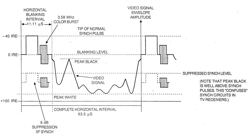
1 Video Signals and Circuits Part 1 Bill Sheets K2MQJ Rudy Graf KA2CWL The transmission of video signals over a carrier wave for broadcasting purposes requires that some format be chosen so as to include picture content, audio (if requires) and synchronization information. With todays wide use of video, some understanding of its nature is desirable if one is to use and interface various video devices such as cameras, monitors, DVD and VCRs, etc. We will discuss those systems that use the standard NTSC (National Television System Committee) video signal format (USA, Canadian, etc.) A typical video signal of the NTSC format is shown in Fig. 1 This is the typical NTSC signal composite video signal transmitted by your local TV station. Several things are evident. The waveform appears complex, with a combination of pulses and another component that has no specific waveshape. The pulse sequence is not obviously simple, but will be found to be repetitive. There are also other high frequency components present. If this waveform were applied to an audio amplifier it would produce a sound like a noisy, raspy buzz which varies somewhat with picture content. The video information, which carries information about the picture may have frequency components up to 4 MHz or so, and appears between periodic, regularly shaped pulses of large amplitude. These pulse signals are used by the receiver or monitor to synchronize and process the picture information and to control those circuits which will produce a display on the monitor screen (CRT or LCD, etc). The picture information is sent as a sequence of elements called lines. The picture is cut up horizontally by the camera into 525 horizontal lines, sent starting top left to top right, and progressively toward the bottom. The lines could be sent in sequence, but in practice, every other line is sent (first, third, fifth and all odd numbered lines) until line 525 is reached then the even lines 2, 4, 6, etc are sent next. Therefore a complete frame consists of two fields, an odd and even. The scan rate is nominally 30 frames a second, with each odd and even field sent 30 times per second. This is called interlaced scanning and makes for a vertical scanning rate of 60 Hz as each field has two vertical scans. The horizontal scan rate is therefore 525 times 30 frames per second or lines per second, which corresponds to a scan frequency of nominally 15,750 Hz. (In actual color TV practice Hz is used, and the vertical scan rate is 1/525 of this or Hz). A scan line occupies actually very close to 63.5 microseconds. However this includes the sync and blanking pulses. The horizontal sync and horizontal blanking pulses make up the horizontal blanking interval. This is about 10.5 microseconds. During those periods between line scans and fields, the picture display should be cut off (made black) as otherwise the return between scan lines of the scan from right to left could show up as a retrace line The horizontal and vertical blanking pulses are used to cut off the display during these intervals. Computer monitors generally use non interlaced scanning and frequently much higher scan rates, up to nearly 80 to 120 Hz vertical and 70 to 80 khz horizontal. Blanking and video signals are commonly separated as well. We will confine most of this discussion to ordinary video as used in television transmission and security work.
 video signal format (USA, Canadian, etc.) A typical video signal of the NTSC format is shown in Fig.")
2 The actual time interval that video is present is then about 52 microseconds. However, the extreme ends of the line scan are usually cut off from viewing by the TV or monitor screen to ensure that the picture fills the entire screen area so the useful scan portion is close to 50 microseconds. In this active part of the horizontal scan interval a video signal of 4 MHz (assume a sine wave) will go through 200 complete cycles. If the positive half of the signal produces a darkening of the display screen and the negative half produces a lightening, we will see 200 pairs of dark and light bands across the screen. If the screen is 2 feet wide (Typical for a 31 inch TV) there will be 100 pairs per foot, or about 8 pairs per inch, and each line will be about 1/16 inch wide. This would be typical of a TV quality picture. A computer monitor must do much better. With active horizontal scan times as short as 10 microseconds, details of as small as.01 to.015 inch must be displayed. For a 21 inch monitor with a horizontal screen width of 16 inches, this means that as many as 1600 lines could be visible. In 10 microseconds, 1600 dark lines would be produced by a video frequency sinewave signal of 160 MHz. Computer monitors typically run at 72 or 96 pixels (picture elements) per inch. This is why video bandwidths of 150 to 300 MHz are commonly encountered in better computer monitors. The typical NTSC TV bandwidth of 4 MHz does not allow definition good enough for computer work, where sharp edges are a must in text work and graphics. The horizontal blanking (narrow) and vertical blanking (wide) pulses are constant and are independent of the transmitted video (picture) signal. The horizontal blanking pulse has a narrower pulse ``piggybacked on top of it. This narrower pulse is called the synch pulse. These synch pulses occur during the horizontal and vertical sweep retrace of the video signal and normally do not produce a visible component on the TV image. They are used to synchronize the TV horizontal sweep circuitry to the video signal. The widest part of the pulse is called the blanking pulse, and has an amplitude such that it reduces the luminance on the CRT (cathode-ray tube) to zero. Naturally, the video level must not be so great as to exceed the synch pulse level, otherwise the level-sensitive synch circuits will be ``confused and the TV picture will not synchronize properly. Deliberate distortion of these pulses is commonly used as a means of scrambling the picture to prevent unauthorized reception, as is done on cable TV. A sync regenerator system (descrambler) is needed to restore these distorted sync pulses to a usable format so the picture can be viewed. The vertical blanking interval (VBI) occurs between fields and at a nominal 60 Hz rate. However, there is a slight difference between the vertical blanking pulse at the beginning of the odd and even fields. The fact that interlacing is used means that there are 525/2 or lines per field. Since there are 30 frames per second, and 60 scans, the ratio of horizontal to vertical scan frequencies is This makes the relative timing of pulses different in successive fields by half a line scan or about microseconds. Also, during the vertical blanking interval (VBI) horizontal synchronization must be maintained. The VBI is equal to about 0.07 of the vertical scan time (16.67 ms), or abour about 1.15 milliseconds. The vertical sync pulse is nine horizontal lines, or about 570 microseconds. It consists of a blanking pulse plus a wide sync pulse about 180 usec wide at the center. This sync pulse is serrated with twice -

3 horizontal frequency pulses. During this time pulses at twice the horizontal rate are added to the vertical blanking pulses, maintaining horizontal sync. The twice horizontal pulses line frequency also makes up for the half line difference in timing between the even and odd fields and are called equalizing pulses for this reason. The vertical pulses are easily filtered out from the horizontal pulses by a simple R-C low pass filter, network, called the vertical integrating network. The output of this is only the 60 Hz vertical pulses, the horizontal pulse components being greatly attenuated. Right after the vertical sync pulses are ten or so blanked lines with only horizontal pulses. These intervals can be used for system test signals or control purposes as their scan lines are normally above the top edge of the picture. By the way, the scan lines are numbered from the beginning of the VBI, so the actual picture does not start until about line 20 (first field) or line 283 (second field) of the picture. If you adjust your TV set so it just starts to lose vertical sync and rolls, (easier on older and low end B/W sets with accessible V and H sync controls) and adjust the contrast and the brightness controls as well, you can see some of this stuff on the wide horizontal bar appearing between frames. A little study of this bar will illustrate just what is happening. The equalizing pulses will appear as a black section at the center of the bar, and test signals in the VBI will appear as black and white line portions on the lowest part of the bar. The color section needs some information to properly sync to the picture as well. Right after the horizontal synch pulse trailing edge, but before the blanking pulse trailing edge, (called ther horizontal pulse back porch ) a signal consisting of eight to eleven sine-wave cycles at 3.58 MHz (actually MHz or 455/2 times the horizontal scan frequency) will be found on color video signals. This signal is the color synch (burst) signal; it is used to synchronize the color circuitry in the TV receiver and turn it on for color programs. This is done by a phase locked loop in the color circuitry, or sometimes it is simply filtered out in a narrowband crystal filter circuit, where it rings a crystal, producing a continuous wave signal at 3.58 MHz. The color synch signal is not needed if the transmitted program is black and white, as is often used in security and surveillance work and other applications where color is unnecessary. Thus, in its absence (during a B/W program), the color circuitry in the TV receiver automatically shuts down. This prevents random noise in the color channels from producing colored snow and streaks in the black-and-white program. However, note that in actual practice, this burst is not always disabled by the programmer during B/W transmissions, as there may be some color information (logos, ID signals, etc) even though the transmission is mainly black and white. This is often seen on cable and satellite TV, where the channel logo in the lower right corner stays in color, even with a black and white movie. Audio information is frequency modulated on a 4.5-MHz signal that is added into the composite video signal, but it may also be modulated on a separate carrier that is 4.5 MHz higher or lower than the picture carrier frequency. This carrier is like a standard FM (frequency modulated) radio signal except the deviation is limited to ±25 khz (monaural) instead of the ±75 khz used for FM broadcasting. Audio preemphasis is also used as in FM broadcast practice, as is stereo transmissiom using multiplex techniques as in FM broadcast, with a Khz pilot and 31.5 Khz subcarrier

4 replacing the 19 and 38 Khz frequencies used in commercial FM stereo. In the TV receiver, this 4.5-MHz signal appears at the video detector and is picked off and processed in a 4.5-MHz limiter/detector (or quadrature demodulator) in much the same way as the 10.7-MHz system used in an FM broadcast receiver. If the signal is not 4.5 MHz, the sound will be absent and only random noise (hiss) will be heard, unless a squelch circuit is used. This will be discussed later as it plays little role in the video, which is our major focus of this article. Note that levels must be maintained and waveform polarities are important. In the NTSC system, a standard level video signal is 1 volt into 75 ohms, with the sync polarity negative. The vertical blanking level is referenced at zero volts. Sometimes the IRE unit is used, in which pure white is + 1 volt, pure black is zero volts, and sync tips are 40 units (-0.4 volts). In actual practice, white is taken as 92 IRE, black at about 7 IRE units. Much video equipment is made to interface with this kind of signal, where the video level varies from zero to 1 volt, and the sync is 0.4 volts. Standard impedance is generally 75 ohms in video work. Due to stringent requirements of waveform, any long leads (over about a foot or so) should be 75 ohm cable with proper terminations and impedance matching. Loss of higher frequencies will result in loss of picture detail. Reflections will show up as ghost lines or image artifacts around the actual subject. Phase delays must be considered when using multiple video sources as phaseshift can distort colors. Remember that the condition for distortionless transmission of information through any medium or network is the presence of flat frequency response and constant time delay with respect to frequency, (linear phase response versus frequency). As aforementioned, there are 15,734 pulses transmitted per second; this corresponds to 525 lines of fields transmitted per second. Each field consists of lines (interlaced scanning), and two fields make a frame. Alternate lines are scanned on each field. (For example; lines 1, 3, 5, 7, etc., of the first field are scanned, and then, lines 2, 4, 6, 8, etc., of the second field are scanned.) For simplicity, we will round off these numbers to 15,750 horizontal and 30 vertical frames per second. Note, that the vertical pulses occur at a 60-Hz rate, but that alternate pulses are slightly different, due to the interlacing. The main point to remember is that these horizontal and vertical pulses and the color burst signal are used for the timing and synchronization necessary to reproduce the TV picture. If any of these pulses are absent, distorted, or altered, it becomes difficult or impossible to synchronize the TV picture. The screen will roll, tear, and the colors will be incorrect, rendering the picture unwatchable. The successful use of the NTSC video signal requires careful attention to levels and polarities of the signal components. The picture components are luminance (brightness) component, and chrominance (color) component which contains the color information, or more correctly, the color difference information. This method of transmitting the chrominance information (color) was employed when the NTSC system was developed half a century ago, for reasons of compatibility with existing B/W TV receivers. This still is a good method for ensuring that a B/W receiver can receive color transmissions, producing a corresponding B/W image and

5 rejecting the color information with no resulting interference or degradation of quality. The color signal is a bit more complex to understand but, basically, it is a MHz (actually MHz) signal that is both amplitude modulated and phase modulated. The amplitude of this signal determines the saturation of a color (whether it is, for example, white, light pink, rose, or red), and the phase determines the hue (whether it is red, orange, yellow, etc.). If the burst-signal phase is used as a reference, a signal in phase with it would produce a greenish-yellow hue. It is important to understand that the amplitude of the composite color signal is used to determine the difference from white; not the intensity of a particular color. In this way, a color signal with a zero level would produce a neutral colored raster, allowing compatibility between color and black-and-white reception on the same TV receiver. Whether the color is, say a dark red or bright red is determined by the luminance component of the signal. For example, a brown object would have the chrominance phase component of an orange color, but a lower luminance component (dark grey), since browns are a dark shades of oranges. A sky blue would have a blue chrominance component with a large luminance component (very light grey). Neutral colors (whites, grays, and blacks) would have zero chrominance component. Near neutrals (beiges, ivories, off whites, etc) would have a very low level of chrominance component. Saturated colors would have a high value of chrominance component. Very bright saturated colors having a high chrominance and luminance component (yellows, greens, cyans, etc) could conceivably produce signal levels exceeding the dynamic range of the system. This amplitude has to be limited, and is one of several reasons why a color TV system cannot reproduce certain colors perfectly. The TV camera that is used for producing a video signal basically divides the televised scene into three image components, these components carrying the red, green, and blue information respectively that is present in the scene. This was done optically using prisms, mirrors, and filters in early cameras, along with three vidicon tubes. It is done today in the solid state cameras with CCD chips having integral color filters or arrays. The camera must generate the sync signals for the horizontal, vertical, and color components, and produce a complete composite video signal. Broadcast and studio camera installations have separate master sync generators, which is necessary in multicamera installations. A sync generator used to occupy a large rack and have many tubes. Today, LSI circuitry does all this in a much smaller package. Sync generator chips are widely available for a few dollars, and complete color CCD camera for under $100 in some instances. The self contained camera must process these components into a complete NTSC format signal that can be directly received on a monitor or fed to various video devices. The three video signals produced in each of the three primary colors (red, green, and blue) have amplitudes that vary with the level of that primary present in the color at a particular point in the scene. We will assume for simplicity that each signal can be between zero and +1 volt, where zero represents none of a particular primary, and +1 is the full amount of that primary. This is commonly called an RGB
. If the burst-signal phase is used as a reference, a signal in phase with it would produce a greenish-yellow hue.")
6 system. This is because these colors are added together in various proportions to reproduce the original scene colors. All reproducible colors are mixtures of these three primaries. White is a mixture of all three at maximum level. Black is a total lack of all three (zero level). A fully saturated pure red object will produce 1 volt of red signal, and zero of green and blue. Similarly, a pure blue will produce 1 volt of blue signal, with zero red and green, etc. Intermediate colors (yellow, orange, etc.) will produce primary levels in two or all three colors, depending on the exact shade of the color. Most colors found in nature will a mixture of all three colors, as pure colors seldom occur outside of test and laboratory situations. The luminance part of the video signal will be discussed first. This is the part that contains brightness and contrast information for the scene. It is the black and white portion and if viewed separately, would produce a black and white (B/W) image as seen on the TV or monitor. However, you cannot simply get a true appearing B-W image by simply combining the three primary colors, of red, green, and blue (RGB). Tonal relationships in the B/W image would suffer, with blues and reds appearing too light and unnatural while greens would appear a little too dark and flat, the image appearing overall muddy and dull. The human eye is more sensitive to green, and less sensitive to red and blue. Therefore this factor has to be taken into account. Also, TV and monitor phosphors have limitations as to exact color and brightness levels obtainable, and CCD cameras tend to favor reds. What is done is to mix the red, green, and blue components in unequal proportions, determined from these considerations. The luminance signal is made up as follows: Luminance (Vy) or Y component = 0.30 Vr Vg Vb The three color video signal components are called Vr, Vg, and Vb, for red, green, and blue, respectively This gives a good, natural appearing black and white image with the various colors appearing as shades of gray that correspond to their percieved brightness in nature, by the human eye. Photography buffs that specialize in B/W work will know what we mean. We want yellows, oranges, and some greens to appear bright, while reds should be a little darker, and blues, purples and browns darker still. Notice that the three components add up to 1.0 or 100 percent, which would represent white. Neutral colors, blacks, greys, and whites, would appear as proportionate combinations of these three colors at lower levels. Grayed or off white colors appear as intermediate combinations of these three primary colors with relative red, green, and blue ratios close to those of neutrals, i.e The video luminance level as seen by the luminance video amplifier and monochrome monitor screen would appear as in the following table. The RGB relative composition is the approximate mixture to get the perceived color, and the Relative Luminance level is the sums of the amplitudes of the RGB components, given in terms of a black to white tonal (grey) scale of zero to one, as seen in a B/W photo or TV image.
 will produce primary levels in two or all three colors, depending on the exact shade of the color.")
7 Perceived Color RGB Relative Composition Relative Luminance level White.30R +.59G +.11B 1.00 White Ivory.30R +.59G +.05 B 0.95 Almost white Yellow.30R +.59G 0.89 Very Light grey Cyan.59G +.11B 0.70 Light grey Orange.30R +.30G 0.60 Green.59G 0.59 Grey.15R +.295G +.055B 0.50 Middle Grey Magenta.30R +.11 B 0.41 Red.30 R 0.30 Dark grey Blue.11B 0.11 Very dark grey Black Black It can be seen that the relative levels of these colors will appear natural. B/W is an abstract concept, as there is no exact relationship between colors and their corresponding grey tones, only what we think would look right. There are some esthetic considerations as well as technical here. However, with this system, the various colors would appear about as bright as the average human eye would see them, but in corresponding shades of grey as given by the value of luminance in the right hand column. So far, we have a color video signal generated with three color video components in the three primaries, with a correct luminance or Y channel. This Y signal will appear as a plain B/W signal, so the color information must be added on in such a way as to be able to recover it and generate the original R,G,and B components at the monitor or receiver so as to get a color image. This will be covered in the next part of this article

8

9
Prepared by: Paul Lee ON Semiconductor http://onsemi.com
 Introduction to Analog Video Prepared by: Paul Lee ON Semiconductor APPLICATION NOTE Introduction Eventually all video signals being broadcasted or transmitted will be digital, but until then analog video
Composite Video Separation Techniques
 TM Composite Video Separation Techniques Application Note October 1996 AN9644 Author: Stephen G. LaJeunesse Introduction The most fundamental job of a video decoder is to separate the color from the black
This document describes how video signals are created and the conversion between different standards. Four different video signals are discussed:
 A technical briefing by J. S. Technology. Introduction. This document describes how video signals are created and the conversion between different standards. Four different video signals are discussed:
Common 16:9 or 4:3 aspect ratio digital television reference test pattern
 Recommendation ITU-R BT.1729 (2005) Common 16:9 or 4:3 aspect ratio digital television reference test pattern BT Series Broadcasting service (television) ii Rec. ITU-R BT.1729 Foreword The role of the
Analog Video Connections Which Should I Use and Why?
 Analog Video Connections Which Should I Use and Why? When converting video to a digital file, there can be several options for how the deck is connected to your digitizing work station. Whether you are
RECOMMENDATION ITU-R BO.786 *
 Rec. ITU-R BO.786 RECOMMENDATION ITU-R BO.786 * MUSE ** system for HDTV broadcasting-satellite services (Question ITU-R /) (992) The ITU Radiocommunication Assembly, considering a) that the MUSE system
Parameter values for the HDTV standards for production and international programme exchange
 Recommendation ITU-R BT.79-6 (6/215) Parameter values for the HDTV standards for production and international programme exchange BT Series Broadcasting service (television) ii Rec. ITU-R BT.79-6 Foreword
Timing Errors and Jitter
 Timing Errors and Jitter Background Mike Story In a sampled (digital) system, samples have to be accurate in level and time. The digital system uses the two bits of information the signal was this big
Scanners and How to Use Them
 Written by Jonathan Sachs Copyright 1996-1999 Digital Light & Color Introduction A scanner is a device that converts images to a digital file you can use with your computer. There are many different types
1. Three-Color Light. Introduction to Three-Color Light. Chapter 1. Adding Color Pigments. Difference Between Pigments and Light. Adding Color Light
 1. Three-Color Light Chapter 1 Introduction to Three-Color Light Many of us were taught at a young age that the primary colors are red, yellow, and blue. Our early experiences with color mixing were blending
EPSON SCANNING TIPS AND TROUBLESHOOTING GUIDE Epson Perfection 3170 Scanner
 EPSON SCANNING TIPS AND TROUBLESHOOTING GUIDE Epson Perfection 3170 Scanner SELECT A SUITABLE RESOLUTION The best scanning resolution depends on the purpose of the scan. When you specify a high resolution,
Television. This chapter introduces you to the subject of TV technology. It embodies almost. Objectives. chapter
 23 chapter Television This chapter introduces you to the subject of TV technology. It embodies almost all the principles and circuits covered elsewhere in this book. Studying TV is an excellent review
Modulation Methods SSB and DSB
 Modulation Methods SSB and DSB William Sheets K2MQJ Rudolf F. Graf KA2CWL SSB or Single Sideband, is a type of AM without the carrier and one sideband. DSB or double sideband is AM with the carrier suppressed,
PCM Encoding and Decoding:
 PCM Encoding and Decoding: Aim: Introduction to PCM encoding and decoding. Introduction: PCM Encoding: The input to the PCM ENCODER module is an analog message. This must be constrained to a defined bandwidth
CBS RECORDS PROFESSIONAL SERIES CBS RECORDS CD-1 STANDARD TEST DISC
 CBS RECORDS PROFESSIONAL SERIES CBS RECORDS CD-1 STANDARD TEST DISC 1. INTRODUCTION The CBS Records CD-1 Test Disc is a highly accurate signal source specifically designed for those interested in making
Designing Custom DVD Menus: Part I By Craig Elliott Hanna Manager, The Authoring House at Disc Makers
 Designing Custom DVD Menus: Part I By Craig Elliott Hanna Manager, The Authoring House at Disc Makers DVD authoring software makes it easy to create and design template-based DVD menus. But many of those
Note monitors controlled by analog signals CRT monitors are controlled by analog voltage. i. e. the level of analog signal delivered through the
 DVI Interface The outline: The reasons for digital interface of a monitor the transfer from VGA to DVI. DVI v. analog interface. The principles of LCD control through DVI interface. The link between DVI
CCTV System Troubleshooting Guide
 Wouldn t be nice to start and finish a CCTV System Project without running into any problems before, during and after the installation is completed. Well, in this article we will try and explain why we
The Phase Modulator In NBFM Voice Communication Systems
 The Phase Modulator In NBFM Voice Communication Systems Virgil Leenerts 8 March 5 The phase modulator has been a point of discussion as to why it is used and not a frequency modulator in what are called
The front end of the receiver performs the frequency translation, channel selection and amplification of the signal.
 Many receivers must be capable of handling a very wide range of signal powers at the input while still producing the correct output. This must be done in the presence of noise and interference which occasionally
HD Radio FM Transmission System Specifications Rev. F August 24, 2011
 HD Radio FM Transmission System Specifications Rev. F August 24, 2011 SY_SSS_1026s TRADEMARKS HD Radio and the HD, HD Radio, and Arc logos are proprietary trademarks of ibiquity Digital Corporation. ibiquity,
Overview. Raster Graphics and Color. Overview. Display Hardware. Liquid Crystal Display (LCD) Cathode Ray Tube (CRT)
 Cathode Ray Tube (CRT)") Raster Graphics and Color Greg Humphreys CS445: Intro Graphics University of Virginia, Fall 2004 Color models Color models Display Hardware Video display devices Cathode Ray Tube (CRT) Liquid Crystal Display
Raster Graphics and Color Greg Humphreys CS445: Intro Graphics University of Virginia, Fall 2004 Color models Color models Display Hardware Video display devices Cathode Ray Tube (CRT) Liquid Crystal Display
Doppler. Doppler. Doppler shift. Doppler Frequency. Doppler shift. Doppler shift. Chapter 19
 Doppler Doppler Chapter 19 A moving train with a trumpet player holding the same tone for a very long time travels from your left to your right. The tone changes relative the motion of you (receiver) and
Introduction to FM-Stereo-RDS Modulation
 Introduction to FM-Stereo-RDS Modulation Ge, Liang Tan, EK Kelly, Joe Verigy, China Verigy, Singapore Verigy US 1. Introduction Frequency modulation (FM) has a long history of its application and is widely
Germanium Diode AM Radio
 Germanium Diode AM Radio LAB 3 3.1 Introduction In this laboratory exercise you will build a germanium diode based AM (Medium Wave) radio. Earliest radios used simple diode detector circuits. The diodes
Lab 1: The Digital Oscilloscope
 PHYSICS 220 Physical Electronics Lab 1: The Digital Oscilloscope Object: To become familiar with the oscilloscope, a ubiquitous instrument for observing and measuring electronic signals. Apparatus: Tektronix
INTRODUCTION TO COMMUNICATION SYSTEMS AND TRANSMISSION MEDIA
 COMM.ENG INTRODUCTION TO COMMUNICATION SYSTEMS AND TRANSMISSION MEDIA 9/6/2014 LECTURES 1 Objectives To give a background on Communication system components and channels (media) A distinction between analogue
FCC CABLE RULES. 76.605 Technical Standards
 CODE OF FEDERAL REGULATIONS TITLE 47 -- TELECOMMUNICATION CHAPTER I -- FEDERAL COMMUNICATIONS COMMISSION SUBCHAPTER C -- BROADCAST RADIO SERVICES PART 76--CABLE TELEVISION SERVICE 76.605 Technical Standards
Agilent 8904A Multifunction Synthesizer dc to 600 khz
 Agilent 8904A Multifunction Synthesizer dc to 600 khz Technical Specifications Build complex waveforms from common signals The Agilent Technologies 8904A Multifunction Synthesizer uses VLSIC technology
Modification Details.
 Front end receiver modification for DRM: AKD Target Communications receiver. Model HF3. Summary. The receiver was modified and capable of receiving DRM, but performance was limited by the phase noise from
Outline. Quantizing Intensities. Achromatic Light. Optical Illusion. Quantizing Intensities. CS 430/585 Computer Graphics I
 CS 430/585 Computer Graphics I Week 8, Lecture 15 Outline Light Physical Properties of Light and Color Eye Mechanism for Color Systems to Define Light and Color David Breen, William Regli and Maxim Peysakhov
This paper will explain some of the more important factors on how UTP wires work; specifically it will cover the following:
 UTP Technology In the late 1970s, unshielded twisted pair (UTP) cabling originated in the computer industry as a means of transmitting digital data over computer networks. This cable was designed to be
CDMA TECHNOLOGY. Brief Working of CDMA
 CDMA TECHNOLOGY History of CDMA The Cellular Challenge The world's first cellular networks were introduced in the early 1980s, using analog radio transmission technologies such as AMPS (Advanced Mobile
AN1200.04. Application Note: FCC Regulations for ISM Band Devices: 902-928 MHz. FCC Regulations for ISM Band Devices: 902-928 MHz
 AN1200.04 Application Note: FCC Regulations for ISM Band Devices: Copyright Semtech 2006 1 of 15 www.semtech.com 1 Table of Contents 1 Table of Contents...2 1.1 Index of Figures...2 1.2 Index of Tables...2
1. Oscilloscope is basically a graph-displaying device-it draws a graph of an electrical signal.
 CHAPTER 3: OSCILLOSCOPE AND SIGNAL GENERATOR 3.1 Introduction to oscilloscope 1. Oscilloscope is basically a graph-displaying device-it draws a graph of an electrical signal. 2. The graph show signal change
Multi-Zone Adjustment
 Written by Jonathan Sachs Copyright 2008 Digital Light & Color Introduction Picture Window s 2-Zone Adjustment and3-zone Adjustment transformations are powerful image enhancement tools designed for images
Chapter 5 Fundamental Concepts in Video
 Chapter 5 Fundamental Concepts in Video 5.1 Types of Video Signals 5.2 Analog Video 5.3 Digital Video 5.4 Further Exploration 1 Li & Drew c Prentice Hall 2003 5.1 Types of Video Signals Component video
Lock - in Amplifier and Applications
 Lock - in Amplifier and Applications What is a Lock in Amplifier? In a nut shell, what a lock-in amplifier does is measure the amplitude V o of a sinusoidal voltage, V in (t) = V o cos(ω o t) where ω o
Diode Applications. by Kenneth A. Kuhn Sept. 1, 2008. This note illustrates some common applications of diodes.
 by Kenneth A. Kuhn Sept. 1, 2008 This note illustrates some common applications of diodes. Power supply applications A common application for diodes is converting AC to DC. Although half-wave rectification
RF Measurements Using a Modular Digitizer
 RF Measurements Using a Modular Digitizer Modern modular digitizers, like the Spectrum M4i series PCIe digitizers, offer greater bandwidth and higher resolution at any given bandwidth than ever before.
MISE - STEREO ENCODER
 MISE - STEREO ENCODER 1. FRONT PANEL CONTROLS and INDICATORS AUDIO LEVEL F1 F2 F3 F4 OVER- MOD F5 F1:AUDIO LEVEL Control The setting of this screwdriver adjustment determines the audio input signal level.
Color Balancing Techniques
 Written by Jonathan Sachs Copyright 1996-1999 Digital Light & Color Introduction Color balancing refers to the process of removing an overall color bias from an image. For example, if an image appears
Basics of Video: From Simple Analog to HDTV
 Basics of Video: From Simple Analog to HDTV Application Note 1695 Authors: Mike Ogier and Tamara Schmitz Video signals can be divided into two categories; analog and digital. Both use a variety of standards,
AM TRANSMITTERS & RECEIVERS
 Reading 30 Ron Bertrand VK2DQ http://www.radioelectronicschool.com AM TRANSMITTERS & RECEIVERS Revision: our definition of amplitude modulation. Amplitude modulation is when the modulating audio is combined
Digital Image Basics. Introduction. Pixels and Bitmaps. Written by Jonathan Sachs Copyright 1996-1999 Digital Light & Color
 Written by Jonathan Sachs Copyright 1996-1999 Digital Light & Color Introduction When using digital equipment to capture, store, modify and view photographic images, they must first be converted to a set
White paper. CCD and CMOS sensor technology Technical white paper
 White paper CCD and CMOS sensor technology Technical white paper Table of contents 1. Introduction to image sensors 3 2. CCD technology 4 3. CMOS technology 5 4. HDTV and megapixel sensors 6 5. Main differences
e-4 AWT07MLED 7 Q TFT LCD MONITOR (LED Backlighted) USER MANUAL
 USER MANUAL") Thank you for purchasing our product. Please read this User s Manual before using the product. Change without Notice AWT07MLED 7 Q TFT LCD MONITOR (LED Backlighted) USER MANUAL e-4 SAFETY PRECAUTIONS Federal
Thank you for purchasing our product. Please read this User s Manual before using the product. Change without Notice AWT07MLED 7 Q TFT LCD MONITOR (LED Backlighted) USER MANUAL e-4 SAFETY PRECAUTIONS Federal
On Cables and Connections A discussion by Dr. J. Kramer
 KRAMER ELECTRONICS LTD. On Cables and Connections A discussion by Dr. J. Kramer We are frequently asked - "what length of cable can I use for a specific application?" Seemingly a simple question, but the
Agilent AN 1316 Optimizing Spectrum Analyzer Amplitude Accuracy
 Agilent AN 1316 Optimizing Spectrum Analyzer Amplitude Accuracy Application Note RF & Microwave Spectrum Analyzers Table of Contents 3 3 4 4 5 7 8 8 13 13 14 16 16 Introduction Absolute versus relative
Quick start guide! Terri Meyer Boake
 Film Editing Tutorial Quick start guide! Terri Meyer Boake 1. Preparing yourself and your files: This information is valid for all film editing software: FCP, Premiere (the version of FC being used is
10-3. SYSTEM TESTING AND DOCUMENTATION
 10-3. SYSTEM TESTING AND DOCUMENTATION System testing and documentation must cover pre-installation testing, sub-system testing, fiber optic cable testing, video link testing, data link testing, acceptance
Video Matrix Switches and Bandwidth
 Video Matrix Switches and Bandwidth TABLE OF CONTENTS What is a Video Matrix Switch?...3 Bandwidth in Video Matrix Switches...4 Bandwidth Variations in Video Systems...4 Measuring Video Matrix Switch Bandwidth...4
K2 CW Filter Alignment Procedures Using Spectrogram 1 ver. 5 01/17/2002
 K2 CW Filter Alignment Procedures Using Spectrogram 1 ver. 5 01/17/2002 It will be assumed that you have already performed the RX alignment procedures in the K2 manual, that you have already selected the
AUDIO. 1. An audio signal is an representation of a sound. a. Acoustical b. Environmental c. Aesthetic d. Electrical
 Essentials of the AV Industry Pretest Not sure if you need to take Essentials? Do you think you know the basics of Audio Visual? Take this quick assessment test on Audio, Visual, and Systems to find out!
Data Transmission. Data Communications Model. CSE 3461 / 5461: Computer Networking & Internet Technologies. Presentation B
 CSE 3461 / 5461: Computer Networking & Internet Technologies Data Transmission Presentation B Kannan Srinivasan 08/30/2012 Data Communications Model Figure 1.2 Studying Assignment: 3.1-3.4, 4.1 Presentation
Physical Layer, Part 2 Digital Transmissions and Multiplexing
 Physical Layer, Part 2 Digital Transmissions and Multiplexing These slides are created by Dr. Yih Huang of George Mason University. Students registered in Dr. Huang's courses at GMU can make a single machine-readable
Tx/Rx A high-performance FM receiver for audio and digital applicatons
 Tx/Rx A high-performance FM receiver for audio and digital applicatons This receiver design offers high sensitivity and low distortion for today s demanding high-signal environments. By Wayne C. Ryder
TV Trouble Shooting Manual
 INFORMATION SOURCE 5 TV Trouble Shooting Manual VOLUME 1 BY MASAAKI MUKAI AND RYOZO KOBAYASHI ASIAN AND PACIFIC SKILL DEVELOPMENT PROGRAMME INTERNATIONAL LABOUR OFFICE ISLAMABAD, PAKISSTAN, 1988 Appendix
TCOM 370 NOTES 99-4 BANDWIDTH, FREQUENCY RESPONSE, AND CAPACITY OF COMMUNICATION LINKS
 TCOM 370 NOTES 99-4 BANDWIDTH, FREQUENCY RESPONSE, AND CAPACITY OF COMMUNICATION LINKS 1. Bandwidth: The bandwidth of a communication link, or in general any system, was loosely defined as the width of
Introduction to Digital Audio
 Introduction to Digital Audio Before the development of high-speed, low-cost digital computers and analog-to-digital conversion circuits, all recording and manipulation of sound was done using analog techniques.
Dolby Vision for the Home
 Dolby Vision for the Home 1 WHAT IS DOLBY VISION? Dolby Vision transforms the way you experience movies, TV shows, and games with incredible brightness, contrast, and color that bring entertainment to
Selecting Receiving Antennas for Radio Tracking
 Selecting Receiving Antennas for Radio Tracking Larry B Kuechle, Advanced Telemetry Systems, Inc. Isanti, Minnesota 55040 lkuechle@atstrack.com The receiving antenna is an integral part of any radio location
TESTS OF 1 MHZ SIGNAL SOURCE FOR SPECTRUM ANALYZER CALIBRATION 7/8/08 Sam Wetterlin
 TESTS OF 1 MHZ SIGNAL SOURCE FOR SPECTRUM ANALYZER CALIBRATION 7/8/08 Sam Wetterlin (Updated 7/19/08 to delete sine wave output) I constructed the 1 MHz square wave generator shown in the Appendix. This
Technical Paper DISPLAY PROFILING SOLUTIONS
 Technical Paper DISPLAY PROFILING SOLUTIONS A REPORT ON 3D LUT CREATION By Joel Barsotti and Tom Schulte A number of display profiling solutions have been developed to correct image rendering errors in
Graphical displays are generally of two types: vector displays and raster displays. Vector displays
 Display technology Graphical displays are generally of two types: vector displays and raster displays. Vector displays Vector displays generally display lines, specified by their endpoints. Vector display
Experiment 3: Double Sideband Modulation (DSB)
") Experiment 3: Double Sideband Modulation (DSB) This experiment examines the characteristics of the double-sideband (DSB) linear modulation process. The demodulation is performed coherently and its strict
Experiment 3: Double Sideband Modulation (DSB) This experiment examines the characteristics of the double-sideband (DSB) linear modulation process. The demodulation is performed coherently and its strict
T = 1 f. Phase. Measure of relative position in time within a single period of a signal For a periodic signal f(t), phase is fractional part t p
, phase is fractional part t p") Data Transmission Concepts and terminology Transmission terminology Transmission from transmitter to receiver goes over some transmission medium using electromagnetic waves Guided media. Waves are guided
Data Transmission Concepts and terminology Transmission terminology Transmission from transmitter to receiver goes over some transmission medium using electromagnetic waves Guided media. Waves are guided
MAINTENANCE & ADJUSTMENT
 MAINTENANCE & ADJUSTMENT Circuit Theory The concept of PLL system frequency synthesization is not of recent development, however, it has not been a long age since the digital theory has been couplet with
How an electronic shutter works in a CMOS camera. First, let s review how shutters work in film cameras.
 How an electronic shutter works in a CMOS camera I have been asked many times how an electronic shutter works in a CMOS camera and how it affects the camera s performance. Here s a description of the way
Color quality guide. Quality menu. Color quality guide. Page 1 of 6
 Page 1 of 6 Color quality guide The Color Quality guide helps users understand how operations available on the printer can be used to adjust and customize color output. Quality menu Menu item Print Mode
NUCLEAR MAGNETIC RESONANCE. Advanced Laboratory, Physics 407, University of Wisconsin Madison, Wisconsin 53706
 (revised 4/21/03) NUCLEAR MAGNETIC RESONANCE Advanced Laboratory, Physics 407, University of Wisconsin Madison, Wisconsin 53706 Abstract This experiment studies the Nuclear Magnetic Resonance of protons
RGB for ZX Spectrum 128, +2, +2A, +3
 RGB for ZX Spectrum 128, +2, +2A, +3 Introduction... 2 Video Circuitry... 3 Audio Circuitry... 8 Lead Wiring... 9 Testing The Lead... 11 Spectrum +2A/+3 RGB Differences... 12 Circuitry Calculations...
Hooking Up Home Theater
 Home Support Technical Articles Hooking Up Home Theatre What is Home Theater? Hooking Up Home Theater Since the mid- to late-1990s, home theater systems have rapidly grown in popularity, as consumers have
DVB-T. The echo performance of. receivers. Theory of echo tolerance. Ranulph Poole BBC Research and Development
 The echo performance of DVB-T Ranulph Poole BBC Research and Development receivers This article introduces a model to describe the way in which a single echo gives rise to an equivalent noise floor (ENF)
Digital Video Measurements. A Guide to Standard and High-Definition Digital Video Measurements
 Digital Video Measurements A Guide to Standard and High-Definition Digital Video Measurements A Guide to Standard and High-Definition Digital Video Measurements Contents In The Beginning 1 Traditional
Objectives. Lecture 4. How do computers communicate? How do computers communicate? Local asynchronous communication. How do computers communicate?
 Lecture 4 Continuation of transmission basics Chapter 3, pages 75-96 Dave Novak School of Business University of Vermont Objectives Line coding Modulation AM, FM, Phase Shift Multiplexing FDM, TDM, WDM
APPLICATION NOTES: Dimming InGaN LED
 APPLICATION NOTES: Dimming InGaN LED Introduction: Indium gallium nitride (InGaN, In x Ga 1-x N) is a semiconductor material made of a mixture of gallium nitride (GaN) and indium nitride (InN). Indium
USING PROFESSIONAL PLASMA DISPLAYS AS EVALUATION GRADE VIDEO MONITORS. Peter H. Putman, CTS ROAM Consulting L.L.C. Doylestown, PA
 USING PROFESSIONAL PLASMA DISPLAYS AS EVALUATION GRADE VIDEO MONITORS Peter H. Putman, CTS ROAM Consulting L.L.C. Doylestown, PA Nearly a decade into the 21 st century, we re seeing a paradigm shift in
CALIBRATION AND OPERATION OF PANASONIC PLASMA MONITORS JULY 2009
 CALIBRATION AND OPERATION OF PANASONIC PLASMA MONITORS JULY 2009 Overview Plasma video monitors provide high resolution images with excellent contrast and dynamic range, low black levels, and saturated
2102642 Computer Vision and Video Electronics
 What is Video? 2102642 Computer Vision and Video Electronics Chapter 7 Video Signals and Standards Suree Pumrin, Ph.D. 1 Video is a collation of images presented so fast they give the illusion of motion;
Filters for Black & White Photography
 Filters for Black & White Photography Panchromatic Film How it works. Panchromatic film records all colors of light in the same tones of grey. Light Intensity (the number of photons per square inch) is
Instruction Guide. Professional VGA to NTSC/PAL TV Converter with Remote VGA2NTSCPRO. The Professionals Source For Hard-to-Find Computer Parts
 VIDEO CONVERTER Professional VGA to NTSC/PAL TV Converter with Remote VGA2NTSCPRO Instruction Guide * Actual product may vary from photo Revised: February 4, 2003 The Professionals Source For Hard-to-Find
Jitter Measurements in Serial Data Signals
 Jitter Measurements in Serial Data Signals Michael Schnecker, Product Manager LeCroy Corporation Introduction The increasing speed of serial data transmission systems places greater importance on measuring
FREQUENCY RESPONSE OF AN AUDIO AMPLIFIER
 2014 Amplifier - 1 FREQUENCY RESPONSE OF AN AUDIO AMPLIFIER The objectives of this experiment are: To understand the concept of HI-FI audio equipment To generate a frequency response curve for an audio
ε: Voltage output of Signal Generator (also called the Source voltage or Applied
 Experiment #10: LR & RC Circuits Frequency Response EQUIPMENT NEEDED Science Workshop Interface Power Amplifier (2) Voltage Sensor graph paper (optional) (3) Patch Cords Decade resistor, capacitor, and
Kit 106. 50 Watt Audio Amplifier
 Kit 106 50 Watt Audio Amplifier T his kit is based on an amazing IC amplifier module from ST Electronics, the TDA7294 It is intended for use as a high quality audio class AB amplifier in hi-fi applications
LAB 7 MOSFET CHARACTERISTICS AND APPLICATIONS
 LAB 7 MOSFET CHARACTERISTICS AND APPLICATIONS Objective In this experiment you will study the i-v characteristics of an MOS transistor. You will use the MOSFET as a variable resistor and as a switch. BACKGROUND
VME IF PHASE MODULATOR UNIT. mod. 205-01
 mod. 205-01 02/06 B 1/12 INDEX 1 DESCRIPTION pg. 3 2 FRONT VIEW pg. 4-5 3 TECHNICAL CHARACTERISTICS pg. 6-7 4 OPERATING INSTRUCTIONS pg. 8 5 ANNEX LIST pg. 12 02/06 B 2/12 1 - DESCRIPTION The PHASE MODULATOR
THE BASICS OF PLL FREQUENCY SYNTHESIS
 Supplementary Reading for 27 - Oscillators Ron Bertrand VK2DQ http://www.radioelectronicschool.com THE BASICS OF PLL FREQUENCY SYNTHESIS The phase locked loop (PLL) method of frequency synthesis is now
Implementation of Digital Signal Processing: Some Background on GFSK Modulation
 Implementation of Digital Signal Processing: Some Background on GFSK Modulation Sabih H. Gerez University of Twente, Department of Electrical Engineering s.h.gerez@utwente.nl Version 4 (February 7, 2013)
Personal Identity Verification (PIV) IMAGE QUALITY SPECIFICATIONS FOR SINGLE FINGER CAPTURE DEVICES
 IMAGE QUALITY SPECIFICATIONS FOR SINGLE FINGER CAPTURE DEVICES") Personal Identity Verification (PIV) IMAGE QUALITY SPECIFICATIONS FOR SINGLE FINGER CAPTURE DEVICES 1.0 SCOPE AND PURPOSE These specifications apply to fingerprint capture devices which scan and capture
Personal Identity Verification (PIV) IMAGE QUALITY SPECIFICATIONS FOR SINGLE FINGER CAPTURE DEVICES 1.0 SCOPE AND PURPOSE These specifications apply to fingerprint capture devices which scan and capture
K8025 VIDEO PATTERN GENERATOR. Check the picture quality of your monitor or TV, ideal for adjustment or troubleshooting.
 K8025 ILLUSTRATED ASSEMBLY MANUAL H8025IP 1 VIDEO PATTERN GENERATOR Check the picture quality of your monitor or TV, ideal for adjustment or troubleshooting. Forum Participate our Velleman Projects Forum
Use and Application of Output Limiting Amplifiers (HFA1115, HFA1130, HFA1135)
") Use and Application of Output Limiting Amplifiers (HFA111, HFA110, HFA11) Application Note November 1996 AN96 Introduction Amplifiers with internal voltage clamps, also known as limiting amplifiers, have
Use and Application of Output Limiting Amplifiers (HFA111, HFA110, HFA11) Application Note November 1996 AN96 Introduction Amplifiers with internal voltage clamps, also known as limiting amplifiers, have
Rodenstock Photo Optics
 Rogonar Rogonar-S Rodagon Apo-Rodagon N Rodagon-WA Apo-Rodagon-D Accessories: Modular-Focus Lenses for Enlarging, CCD Photos and Video To reproduce analog photographs as pictures on paper requires two
LINE IN, LINE OUT TO TV, VIDEO IN, VIDEO OUT
 1 Based on the information you provided we are unable to match you with a specific hookup recommendation. For your convenience this document provides the four most common hookup configurations for the
1. Introduction to image processing
 1 1. Introduction to image processing 1.1 What is an image? An image is an array, or a matrix, of square pixels (picture elements) arranged in columns and rows. Figure 1: An image an array or a matrix
CLOCK AND SYNCHRONIZATION IN SYSTEM 6000
 By Christian G. Frandsen Introduction This document will discuss the clock, synchronization and interface design of TC System 6000 and deal with several of the factors that must be considered when using
SPECTRUM MONITOR MC-277B
 SPECTRUM MONITOR 1 GENERAL INFORMATION 1.1 Description The field level meter is designed to take the required measurements in a collective antenna and/or satellite system. It covers the television, hyperband
MONOCHROME RGB YCbCr VIDEO DIGITIZER
 Active Silicon SNAPPER-PMC-8/24 MONOCHROME RGB YCbCr VIDEO DIGITIZER High quality analogue video acquisition board with square pixel sampling for CCIR, EIA (RS-170) standards, and nonstandard video formats.