Course in ANSYS. Modeling reviewed Boolean s. ANSYS Computational Mechanics, AAU, Esbjerg
|
|
|
- Leo Harmon
- 9 years ago
- Views:
Transcription
1 Course in Modeling reviewed Boolean s

2 Course Outline Introduction Lesson 1. Modeling reviewed Boolean s Lesson 2. Boolean s + meshing issues Lesson 3. Operate + meshing issues Lesson 4. Import + meshing issues Lesson 5. Meshing advanced topics Lesson 1 Part 2 2

3 Citation of the day Finite Element Analysis makes a good engineer great, and a bad engineer dangerous! Robert D. Cook, Professor of Mechanical Engineering, University of Wisconsin, Madison Lesson 1 Part 2 3

4 Modeling Programme for Lesson: Modeling considerations Element Type Real Constants Material Properties Sections Geometry/Modeling WorkPlane & Coordinate systems Keypoints Lines Areas Volumes Meshing BUILD THE MODEL Lesson 1 Part 2 4

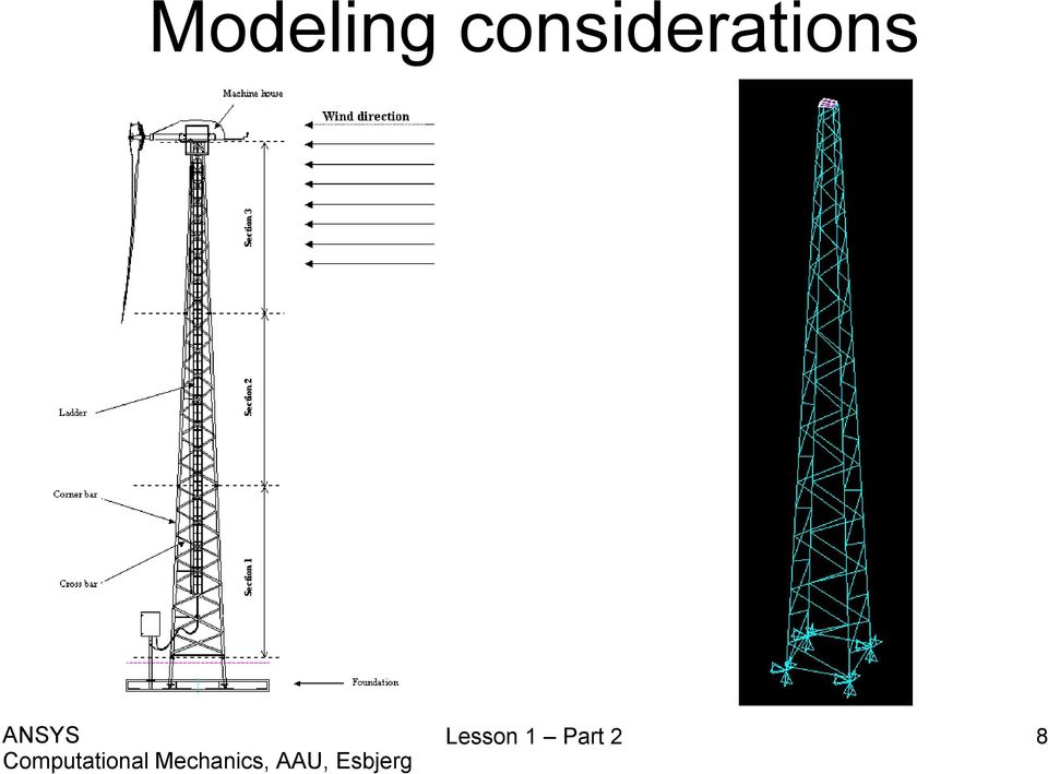
5 Modeling considerations As you begin your model generation, you will (consciously or unconsciously) make a number of decisions that determine how you will mathematically simulate the physical system: What are the objectives of your analysis? Will you need to vary/modify model data? Will you need to change the geometric topology of the model, e.g. add holes to the model? Will you model all, or just a portion, of the physical system? How much detail will you include in your model? What kinds of elements will you use? How dense should your finite element mesh be? In general, you will attempt to balance computational expense (CPU time, etc.) against precision of results as you answer these questions. The decisions you make in the planning stage of your analysis will largely govern the success or failure of your analysis efforts. Lesson 1 Part 2 5
 against precision of results as you answer these questions.")
6 Modeling considerations Linear or Higher Order Elements Take Advantage of Symmetry The axis of symmetry must coincide with the global Cartesian Y-axis. Negative nodal X-coordinates are not permitted. The global Cartesian Y-direction represents the axial direction, the global Cartesian X-direction represents the radial direction, and the global Cartesian Z-direction corresponds to the circumferential direction. Your model should be assembled using appropriate element types: For axisymmetric models, use applicable 2-D solids with KEYOPT(3) = 1, and/or axisymmetric shells. In addition, various link, contact, combination, and surface elements can be included in a model that also contains axisymmetric solids or shells. (The program will not realize that these "other" elements are axisymmetric unless axisymmetric solids or shells are present.) How Much Detail to Include Appropriate Mesh Density Lesson 1 Part 2 6

7 Modeling considerations Each point have an infinite number of deformation state variables, i.e. degrees of freedom (dof) Transformation Real model Continuum Each point have a finite number of deformation state variables (u,v), i.e. degrees of freedom Analysis model Discrete Lesson 1 Part 2 7
, i.e. degrees of freedom Analysis model Discrete Lesson 1 Part 2 7")
8 Modeling considerations Lesson 1 Part 2 8
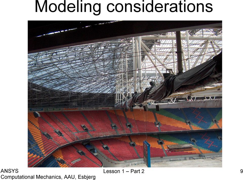
9 Modeling considerations Lesson 1 Part 2 9
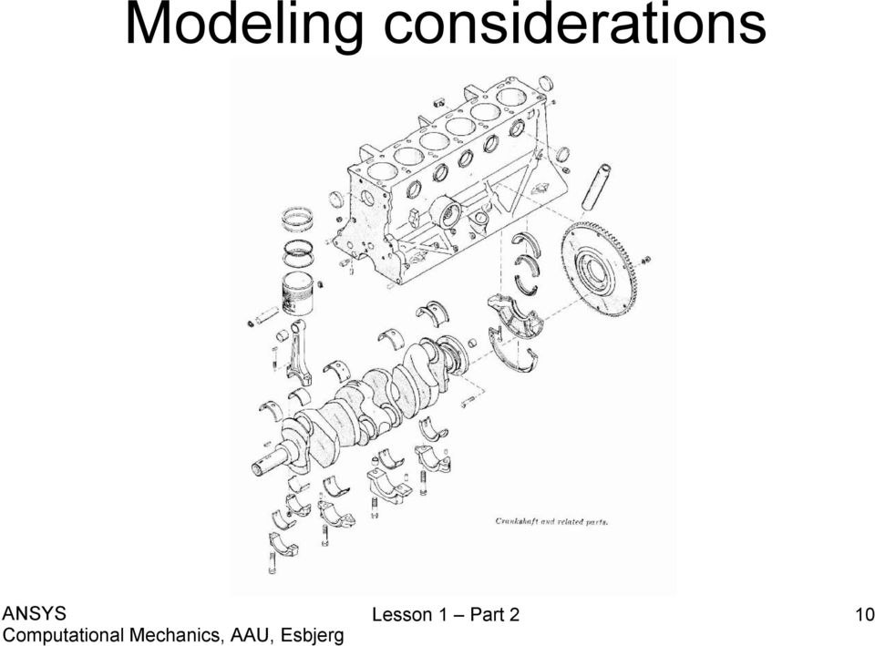
10 Modeling considerations Lesson 1 Part 2 10
11 Modeling considerations WHEEL LOADER REALIZATION - a model and an architecture that enables simulation in a process context By Ulf Sellgren ISRN KTH/MMK/R 03/07 SE TRITA-MMK 2003:07 ISSN Lesson 1 Part 2 11

12 Modeling considerations Lesson 1 Part 2 12

13 Modeling considerations Lesson 1 Part 2 13

14 Modeling considerations Lesson 1 Part 2 14

15 Modeling considerations Characterization of problem Rod Beam Disk Plate Shell Solid Lesson 1 Part 2 15

16 Modeling considerations The program does not assume a system of units for your analysis. Units must however be consistent for all input data. Lesson 1 Part 2 16

17 Geometry/Modelling Creating a solid model within. Using direct generation. Importing a model created in a computeraided design (CAD) system. Lesson 1 Part 2 17
 system.")
18 Coordinate systems Global and local coordinate systems are used to locate geometry items (nodes, keypoints, etc.) in space. The display coordinate system determines the system in which geometry items are listed or displayed. The nodal coordinate system defines the degree of freedom directions at each node and the orientation of nodal results data. The element coordinate system determines the orientation of material properties and element results data. The results coordinate system is used to transform nodal or element results data to a particular coordinate system for listings, displays, or general postprocessing operations (POST1). The working plane, which is separate from the coordinate systems discussed in this chapter, is used to locate geometric primitives during the modeling process. Lesson 1 Part 2 18

19 Coordinate systems (a) Cartesian (X, Y, Z components) coordinate system 0 (C.S.0) (b) Cylindrical (R, θ, Z components) coordinate system 1 (C.S.1) (c) Spherical (R, θ, φ components) coordinate system 2 (C.S.2) (d) Cylindrical (R, θ, Y components) coordinate system 5 (C.S.5) Lesson 1 Part 2 19

20 z Modeling (coordinates) Cartesian z Cylindrical z Spherical (x,y,z) (r,θ,z) φ (r,θ,φ) z x y x θ r y x θ r y General Curvilinear Coordinates General orthogonal Coordinates Lesson 1 Part 2 20

21 Geometry/Modelling Create geometrical entities Operate perform Boolean operations Move / Modify move or modify geometrical entities Copy copy geometrical entities Delete geometrical entities Update Geom update the geometry in relation to for example buckling analysis Lesson 1 Part 2 21
22 Modeling - Create The hierarchy of modeling entities is as listed below: Elements (and Element Loads) Nodes (and Nodal Loads) Volumes (and Solid-Model Body Loads) Areas (and Solid-Model Surface Loads) Lines (and Solid-Model Line Loads) Keypoints (and Solid-Model Point Loads) Lesson 1 Part 2 22
23 Example - Grinding shield Lesson 1 Part 2 23
24 Example - Grinding shield Lesson 1 Part 2 24
25 Example - Grinding shield Lesson 1 Part 2 25
26 Example - Grinding shield Modeling considerations Model storage *.lgw or *.db? Element type? Level of detail? Mesh method? Allow model modifications? Type of analysis to perform? Material models? Boundary conditions and loads? Lesson 1 Part 2 26
27 Example - Grinding shield Modeling considerations /PREP7 K,1,56,,, K,2,60,,, K,3,63,3,, K,4,63,19,, K,5,60,22,, K,6,30,32,, K,7,,32,, K,8,,29.5,, K,9,30,29.5,, K,10,59.5,20,, K,11,60.5,19,, K,12,60.5,3,, K,13,60,2.5,, K,14,56,2.5,, K,100,,,, K,200,20,,-6, K,201,20,40,-6, K,300,-20,,-6, K,301,-20,40,-6, Make a directory, e.g. c:\fem\grinding-shield Change directory in to c:\fem\grinding-shield Make a new text file in c:\fem\grinding-shield Rename from New textdocument.txt to grinding-shield-kp.lgw Open with, e.g. Notepad Enter the text shown Model storage *.lgw or *.db? Element type? Level of detail? Mesh method? Allow model modifications? Type of analysis to perform? Material models? Boundary conditions and loads? Lesson 1 Part 2 27
28 Example - Grinding shield Modeling considerations /PREP7 LSTR, 1, 2 LSTR, 3, 4 LSTR, 5, 6 LSTR, 6, 7 LSTR, 7, 8 LSTR, 8, 9 LSTR, 9, 10 LSTR, 11, 12 LSTR, 13, 14 LSTR, 14, 1!* L2TAN,1,2!* L2TAN,-9,-8!* L2TAN,2,3!* L2TAN,-8,-7 LSTR, 9, 6 LSTR, 5, 10 LSTR, 4, 11 LSTR, 3, 12 LSTR, 2, 13 Make a new text file in c:\fem\grinding-shield Rename from New textdocument.txt to grinding-shieldlines.lgw Open with, e.g. Notepad Enter the text shown Model storage *.lgw or *.db? Element type? Level of detail? Mesh method? Allow model modifications? Type of analysis to perform? Material models? Boundary conditions and loads? Lesson 1 Part 2 28
29 Example - Grinding shield Modeling considerations /PREP7 AL,4,5,6,15 AL,15,16,3,7 AL,16,13,17,14 AL,17,2,18,8 AL,18,12,19,11 AL,19,10,9,1!* CIRCLE,100,15,7,,, AL,20,21,22,23!* CIRCLE,200,3,201,,, AL,24,25,26,27!* CIRCLE,300,3,301,,, AL,28,29,30,31 Make a new text file in c:\fem\grinding-shield Rename from New textdocument.txt to grinding-shieldareas.lgw Open with, e.g. Notepad Enter the text shown A GOOD TIME TO SAVE AS *.db Model storage *.lgw or *.db? Element type? Level of detail? Mesh method? Allow model modifications? Type of analysis to perform? Material models? Boundary conditions and loads? Lesson 1 Part 2 29
30 Modeling - Operate Perform geometrical operations in order to obtain new geometrical entities Lesson 1 Part 2 30
31 Example - Grinding shield Modeling considerations Enter the command sequence in the command line \PREP7 VROTAT,1,2,3,4,5,6,8,7,180,, A GOOD TIME TO SAVE AS *.db Model storage *.lgw or *.db? Element type? Level of detail? Mesh method? Allow model modifications? Type of analysis to perform? Material models? Boundary conditions and loads? Lesson 1 Part 2 31
32 Example - Grinding shield Modeling considerations Enter the command sequence in the command line \PREP7 VOFFST,7,40, VOFFST,8,40, VOFFST,9,40, A GOOD TIME TO SAVE AS *.db Model storage *.lgw or *.db? Element type? Level of detail? Mesh method? Allow model modifications? Type of analysis to perform? Material models? Boundary conditions and loads? Lesson 1 Part 2 32
33 Modeling - Move/Modify Move or modify locations or sizes of geometrical entities Lesson 1 Part 2 33
34 Modeling - Copy Copy geometrical entities to new geometrical entities with new locations Lesson 1 Part 2 34
35 Modeling - Delete The hierarchy of modeling entities is as listed below: Elements (and Element Loads) Nodes (and Nodal Loads) Volumes (and Solid-Model Body Loads) Areas (and Solid-Model Surface Loads) Lines (and Solid-Model Line Loads) Keypoints (and Solid-Model Point Loads) Lesson 1 Part 2 35
36 Modeling - Update Geom Adds displacements from a previous analysis and updates the geometry of the finite element model to the deformed configuration. Lesson 1 Part 2 36
37 Booleans - Intersect LINL (Line Intersect Line) AINA (Area Intersect Area) Lesson 1 Part 2 37
38 Booleans - Intersect VINV (Volume Intersect Volume) LINA (Line Intersect Area) Lesson 1 Part 2 38
39 Booleans - Intersect LINV (Line Intersect Volume) AINV (Area Intersect Volume) Lesson 1 Part 2 39
40 Booleans - Add AADD (Add Areas) VADD (Add Volumes) Lesson 1 Part 2 40
41 Booleans - Subtract LSBL (Line Subtract Line) ASBA (Area Subtract Area) Lesson 1 Part 2 41
42 Booleans - Subtract VSBV (Volume Subtract Volume) LSBA (Line Subtract Area) Lesson 1 Part 2 42
43 Example - Grinding shield Modeling considerations Enter the command sequence in the command line \PREP7 VSBV,ALL, 13!* VSBV,ALL, 14!* VSBV,ALL, 15 Model storage *.lgw or *.db? Element type? Level of detail? Mesh method? Allow model modifications? Type of analysis to perform? Material models? Boundary conditions and loads? Lesson 1 Part 2 43
44 Booleans - Subtract LSBV (Line Subtract Volume) ASBV (Area Subtract Volume) Lesson 1 Part 2 44
45 Booleans - Subtract ASBL (Area Subtract Line) VSBA (Volume Subtract Area) Lesson 1 Part 2 45
46 Booleans - Overlap LOVLAP (Line Overlap Line) AOVLAP (Area Overlap Area) VOVLAP (Volume Overlap Volume) Lesson 1 Part 2 46
47 Booleans - Glue LGLUE (Line Glue Line) AGLUE (Area Glue Area) VGLUE (Volume Glue Volume) Lesson 1 Part 2 47
ANSYS Modeling and Meshing Guide
 ANSYS Modeling and Meshing Guide ANSYS Release 10.0 002184 August 2005 ANSYS, Inc. and ANSYS Europe, Ltd. are UL registered ISO 9001:2000 Companies. ANSYS Modeling and Meshing Guide ANSYS Release 10.0
Begin creating the geometry by defining two Circles for the spherical endcap, and Subtract Areas to create the vessel wall.
 ME 477 Pressure Vessel Example 1 ANSYS Example: Axisymmetric Analysis of a Pressure Vessel The pressure vessel shown below is made of cast iron (E = 14.5 Msi, ν = 0.21) and contains an internal pressure
Course in. FEM ANSYS Workbench/CAD
 Course in 3D Modeling FEM - ANSYS Classic Lecture 1 - Introduction: Introduction to FEM ANSYS Basics Analysis phases Geometric modeling The first model: Beam model Lecture 2 - Preprocessor: Geometric modeling
List of Problems Solved Introduction p. 1 Concept p. 1 Nodes p. 3 Elements p. 4 Direct Approach p. 5 Linear Spring p. 5 Heat Flow p.
 Preface p. v List of Problems Solved p. xiii Introduction p. 1 Concept p. 1 Nodes p. 3 Elements p. 4 Direct Approach p. 5 Linear Spring p. 5 Heat Flow p. 6 Assembly of the Global System of Equations p.
The elements used in commercial codes can be classified in two basic categories:
 CHAPTER 3 Truss Element 3.1 Introduction The single most important concept in understanding FEA, is the basic understanding of various finite elements that we employ in an analysis. Elements are used for
Course in ANSYS. Import + meshing issues. ANSYS Part 2 Computational Mechanics, AAU, Esbjerg
 Course in ANSYS Import + meshing issues Course Outline Introduction Lesson 1. Modeling reviewed Boolean s Lesson 2. Boolean s + meshing issues Lesson 3. Operate + meshing issues Lesson 4. Import + meshing
CAE -Finite Element Method
 16.810 Engineering Design and Rapid Prototyping CAE -Finite Element Method Instructor(s) Prof. Olivier de Weck January 11, 2005 Plan for Today Hand Calculations Aero Æ Structures FEM Lecture (ca. 45 min)
CAE -Finite Element Method
 16.810 Engineering Design and Rapid Prototyping Lecture 3b CAE -Finite Element Method Instructor(s) Prof. Olivier de Weck January 16, 2007 Numerical Methods Finite Element Method Boundary Element Method
The Basics of FEA Procedure
 CHAPTER 2 The Basics of FEA Procedure 2.1 Introduction This chapter discusses the spring element, especially for the purpose of introducing various concepts involved in use of the FEA technique. A spring
PARAMETRIC MODELING. David Rosen. December 1997. By carefully laying-out datums and geometry, then constraining them with dimensions and constraints,
 1 of 5 11/18/2004 6:24 PM PARAMETRIC MODELING David Rosen December 1997 The term parametric modeling denotes the use of parameters to control the dimensions and shape of CAD models. Think of a rubber CAD
Course in. FEM ANSYS Classic
 Course in Introduction Introduction Presentation Anders Schmidt Kristensen M.Sc. in Mechanical Eng. from Aalborg University in 1993 Ph.D. in Mechanical Eng. from Aalborg University in 1997 Consultant for
Finite Element Method
 16.810 (16.682) Engineering Design and Rapid Prototyping Finite Element Method Instructor(s) Prof. Olivier de Weck [email protected] Dr. Il Yong Kim [email protected] January 12, 2004 Plan for Today FEM Lecture
Finite Element Method (ENGC 6321) Syllabus. Second Semester 2013-2014
 Syllabus. Second Semester 2013-2014") Finite Element Method Finite Element Method (ENGC 6321) Syllabus Second Semester 2013-2014 Objectives Understand the basic theory of the FEM Know the behaviour and usage of each type of elements covered
Finite Element Method Finite Element Method (ENGC 6321) Syllabus Second Semester 2013-2014 Objectives Understand the basic theory of the FEM Know the behaviour and usage of each type of elements covered
New design of a pressure vessel subjected to blast loads
 New design of a pressure vessel subjected to blast loads L.Cousin, P.Evrard CEA, DAM, DIF, F91297 Arpajon, France Abstract: A new design of containment vessel has been proposed to conduct confined detonation
An Overview of the Finite Element Analysis
 CHAPTER 1 An Overview of the Finite Element Analysis 1.1 Introduction Finite element analysis (FEA) involves solution of engineering problems using computers. Engineering structures that have complex geometry
Finite Element Formulation for Plates - Handout 3 -
 Finite Element Formulation for Plates - Handout 3 - Dr Fehmi Cirak (fc286@) Completed Version Definitions A plate is a three dimensional solid body with one of the plate dimensions much smaller than the
Shell Elements in ABAQUS/Explicit
 ABAQUS/Explicit: Advanced Topics Appendix 2 Shell Elements in ABAQUS/Explicit ABAQUS/Explicit: Advanced Topics A2.2 Overview ABAQUS/Explicit: Advanced Topics ABAQUS/Explicit: Advanced Topics A2.4 Triangular
Plates and Shells: Theory and Computation - 4D9 - Dr Fehmi Cirak (fc286@) Office: Inglis building mezzanine level (INO 31)
 Office: Inglis building mezzanine level (INO 31)") Plates and Shells: Theory and Computation - 4D9 - Dr Fehmi Cirak (fc286@) Office: Inglis building mezzanine level (INO 31) Outline -1-! This part of the module consists of seven lectures and will focus
Plates and Shells: Theory and Computation - 4D9 - Dr Fehmi Cirak (fc286@) Office: Inglis building mezzanine level (INO 31) Outline -1-! This part of the module consists of seven lectures and will focus
Tutorial for Assignment #3 Heat Transfer Analysis By ANSYS (Mechanical APDL) V.13.0
 V.13.0") Tutorial for Assignment #3 Heat Transfer Analysis By ANSYS (Mechanical APDL) V.13.0 1 Problem Description This exercise consists of an analysis of an electronics component cooling design using fins: All
Tutorial for Assignment #3 Heat Transfer Analysis By ANSYS (Mechanical APDL) V.13.0 1 Problem Description This exercise consists of an analysis of an electronics component cooling design using fins: All
(Seattle is home of Boeing Jets)
") Dr. Faeq M. Shaikh Seattle, Washington, USA (Seattle is home of Boeing Jets) 1 Pre Requisites for Today s Seminar Basic understanding of Finite Element Analysis Working Knowledge of Laminate Plate Theory
Dr. Faeq M. Shaikh Seattle, Washington, USA (Seattle is home of Boeing Jets) 1 Pre Requisites for Today s Seminar Basic understanding of Finite Element Analysis Working Knowledge of Laminate Plate Theory
Tutorial for Assignment #2 Gantry Crane Analysis By ANSYS (Mechanical APDL) V.13.0
 V.13.0") Tutorial for Assignment #2 Gantry Crane Analysis By ANSYS (Mechanical APDL) V.13.0 1 Problem Description Design a gantry crane meeting the geometry presented in Figure 1 on page #325 of the course textbook
Tutorial for Assignment #2 Gantry Crane Analysis By ANSYS (Mechanical APDL) V.13.0 1 Problem Description Design a gantry crane meeting the geometry presented in Figure 1 on page #325 of the course textbook
3 Concepts of Stress Analysis
 3 Concepts of Stress Analysis 3.1 Introduction Here the concepts of stress analysis will be stated in a finite element context. That means that the primary unknown will be the (generalized) displacements.
ANSYS TUTORIAL ANSYS 8.1 Analysis of a Spring System. John R. Baker; phone: 270-534-3114; email: [email protected]
 Copyright 2001-2005, John R. Baker ANSYS TUTORIAL ANSYS 8.1 Analysis of a Spring System John R. Baker; phone: 270-534-3114; email: [email protected] This exercise is intended only as an educational tool
Lap Fillet Weld Calculations and FEA Techniques
 Lap Fillet Weld Calculations and FEA Techniques By: MS.ME Ahmad A. Abbas Sr. Analysis Engineer [email protected] www.advancedcae.com Sunday, July 11, 2010 Advanced CAE All contents Copyright
CHAPTER 4 4 NUMERICAL ANALYSIS
 41 CHAPTER 4 4 NUMERICAL ANALYSIS Simulation is a powerful tool that engineers use to predict the result of a phenomenon or to simulate the working situation in which a part or machine will perform in
Back to Elements - Tetrahedra vs. Hexahedra
 Back to Elements - Tetrahedra vs. Hexahedra Erke Wang, Thomas Nelson, Rainer Rauch CAD-FEM GmbH, Munich, Germany Abstract This paper presents some analytical results and some test results for different
Chapter 22: Electric Flux and Gauss s Law
 22.1 ntroduction We have seen in chapter 21 that determining the electric field of a continuous charge distribution can become very complicated for some charge distributions. t would be desirable if we
Piston Ring. Problem:
 Problem: A cast-iron piston ring has a mean diameter of 81 mm, a radial height of h 6 mm, and a thickness b 4 mm. The ring is assembled using an expansion tool which separates the split ends a distance
Linear Static Analysis of a Cantilever Beam Using Beam Library (SI Units)
") APPENDIX A Linear Static Analysis of a Cantilever Beam Using Beam Library (SI Units) Objectives: Create a geometric representation of a cantilever beam. Use the geometry model to define an MSC.Nastran
APPENDIX A Linear Static Analysis of a Cantilever Beam Using Beam Library (SI Units) Objectives: Create a geometric representation of a cantilever beam. Use the geometry model to define an MSC.Nastran
CosmosWorks Centrifugal Loads
 CosmosWorks Centrifugal Loads (Draft 4, May 28, 2006) Introduction This example will look at essentially planar objects subjected to centrifugal loads. That is, loads due to angular velocity and/or angular
Pro/ENGINEER Wildfire 4.0 Basic Design
 Introduction Datum features are non-solid features used during the construction of other features. The most common datum features include planes, axes, coordinate systems, and curves. Datum features do
ANSYS Example: Transient Thermal Analysis of a Pipe Support Bracket
 ME 477 Transient Thermal Example 1 ANSYS Example: Transient Thermal Analysis of a Pipe Support Bracket The section of pipe shown below is a representative section of a longer pipe carrying a hot fluid
Computer Aided Design (CAD), ME 530.414, JHU Professor Dan Stoianovici, [email protected]
, ME 530.414, JHU Professor Dan Stoianovici, dss@jhu.edu") Computer Aided Design (CAD), ME 530.414, JHU Professor Dan Stoianovici, [email protected] COURSE DESCRIPTION: The course outlines modern solid modeling design, analysis, simulation, and manufacturing of mechanical
Computer Aided Design (CAD), ME 530.414, JHU Professor Dan Stoianovici, [email protected] COURSE DESCRIPTION: The course outlines modern solid modeling design, analysis, simulation, and manufacturing of mechanical
MASTER DEGREE PROJECT
 MASTER DEGREE PROJECT Finite Element Analysis of a Washing Machine Cylinder Thesis in Applied Mechanics one year Master Degree Program Performed : Spring term, 2010 Level Author Supervisor s Examiner :
Computer Graphics. Geometric Modeling. Page 1. Copyright Gotsman, Elber, Barequet, Karni, Sheffer Computer Science - Technion. An Example.
 An Example 2 3 4 Outline Objective: Develop methods and algorithms to mathematically model shape of real world objects Categories: Wire-Frame Representation Object is represented as as a set of points
CAD-BASED DESIGN PROCESS FOR FATIGUE ANALYSIS, RELIABILITY- ANALYSIS, AND DESIGN OPTIMIZATION
 CAD-BASED DESIGN PROCESS FOR FATIGUE ANALYSIS, RELIABILITY- ANALYSIS, AND DESIGN OPTIMIZATION K.K. Choi, V. Ogarevic, J. Tang, and Y.H. Park Center for Computer-Aided Design College of Engineering The
High-end FEA pre/postprocessor
 Advanced FEM: High-end FEA pre/postprocessor NX CAE Benefits Speed analysis modeling processes by up to 70 percent Increase product quality by rapidly simulating design trade-off studies Lower overall
This tutorial provides a recipe for simulating L
 Pipe Flow Tutorial for STAR-CCM+ ME 448/548 February 5, 2014 Gerald Recktenwald [email protected] 1 Overview This tutorial provides a recipe for simulating laminar flow in a pipe with STAR- L CCM+. The
STRUCTURAL ANALYSIS SKILLS
 STRUCTURAL ANALYSIS SKILLS ***This document is held up to a basic level to represent a sample for our both theoretical background & software capabilities/skills. (Click on each link to see the detailed
CATIA V5 FEA Tutorials Releases 12 & 13
 CATIA V5 FEA Tutorials Releases 12 & 13 Nader G. Zamani University of Windsor SDC PUBLICATIONS Schroff Development Corporation www.schroff.com www.schroff-europe.com Visit our website to learn more about
HowTo Rhino & ICEM. 1) New file setup: choose Millimeter (automatically converts to Meters if imported to ICEM)
 New file setup: choose Millimeter (automatically converts to Meters if imported to ICEM)") HowTo Rhino & ICEM Simple 2D model 1) New file setup: choose Millimeter (automatically converts to Meters if imported to ICEM) 2) Set units: File Properties Units: Model units: should already be Millimeters
HowTo Rhino & ICEM Simple 2D model 1) New file setup: choose Millimeter (automatically converts to Meters if imported to ICEM) 2) Set units: File Properties Units: Model units: should already be Millimeters
Reliable FE-Modeling with ANSYS
 Reliable FE-Modeling with ANSYS Thomas Nelson, Erke Wang CADFEM GmbH, Munich, Germany Abstract ANSYS is one of the leading commercial finite element programs in the world and can be applied to a large
NATIONAL TECHNICAL UNIVERSITY OF ATHENS (N.T.U.A.)
") NATIONAL TECHNICAL UNIVERSITY OF ATHENS (N.T.U.A.) MECHANICAL ENGINEERING DEPARTMENT LABORATORY OF MACHINES ELEMENTS Ansys Multiphysics (v. 12) tutorial for electrostatic finite element analysis on spur
NATIONAL TECHNICAL UNIVERSITY OF ATHENS (N.T.U.A.) MECHANICAL ENGINEERING DEPARTMENT LABORATORY OF MACHINES ELEMENTS Ansys Multiphysics (v. 12) tutorial for electrostatic finite element analysis on spur
TWO-DIMENSIONAL TRANSFORMATION
 CHAPTER 2 TWO-DIMENSIONAL TRANSFORMATION 2.1 Introduction As stated earlier, Computer Aided Design consists of three components, namely, Design (Geometric Modeling), Analysis (FEA, etc), and Visualization
Creating a 2D Geometry Model
 Creating a 2D Geometry Model This section describes how to build a 2D cross section of a heat sink and introduces 2D geometry operations in COMSOL. At this time, you do not model the physics that describe
MODELLING AND COMPUTATIONAL ANALYSIS
 DAAAM INTERNATIONAL SCIENTIFIC BOOK 2011 pp. 205-214 CHAPTER 17 MODELLING AND COMPUTATIONAL ANALYSIS OF SPINDLES IN COMSOL SYSTEM WOLNY, R. Abstract: This paper presents the opportunities of COMSOL multiphysics
Tutorial: 3D Pipe Junction Using Hexa Meshing
 Tutorial: 3D Pipe Junction Using Hexa Meshing Introduction In this tutorial, you will generate a mesh for a three-dimensional pipe junction. After checking the quality of the first mesh, you will create
AN INTRODUCTORY ANSYS TUTORIAL: SOLVING A STATIC TRUSS PROBLEM
 AN INTRODUCTORY ANSYS TUTORIAL: SOLVING A STATIC TRUSS PROBLEM Rajesh Bhaskaran Cornell University E-mail: [email protected] This is a quick-and-dirty introductory tutorial to the ANSYS software package
Force measurement. Forces VECTORIAL ISSUES ACTION ET RÉACTION ISOSTATISM
 Force measurement Forces VECTORIAL ISSUES In classical mechanics, a force is defined as "an action capable of modifying the quantity of movement of a material point". Therefore, a force has the attributes
Gradient, Divergence and Curl in Curvilinear Coordinates
 Gradient, Divergence and Curl in Curvilinear Coordinates Although cartesian orthogonal coordinates are very intuitive and easy to use, it is often found more convenient to work with other coordinate systems.
820446 - ACMSM - Computer Applications in Solids Mechanics
 Coordinating unit: 820 - EUETIB - Barcelona College of Industrial Engineering Teaching unit: 737 - RMEE - Department of Strength of Materials and Structural Engineering Academic year: Degree: 2015 BACHELOR'S
Optical modeling of finite element surface displacements using commercial software
 Optical modeling of finite element surface displacements using commercial software Keith B. Doyle, Victor L. Genberg, Gregory J. Michels, Gary R. Bisson Sigmadyne, Inc. 803 West Avenue, Rochester, NY 14611
511 - Creating Structural Frame Designs
 4 th Generation VLC courtesy of Edison2 511 - Creating Structural Frame Designs Rahul Kulkarni, Manager, Product Design, Pune Center, Siemens PLM Software #SEU13 Agenda: 511 - Creating Structural Frame
World-class finite element analysis (FEA) solution for the Windows desktop
 solution for the Windows desktop") Answers for industry. World-class finite element analysis (FEA) solution for the Windows desktop Benefits Significantly speed up the design process by bringing simulation closer to design and reducing
Answers for industry. World-class finite element analysis (FEA) solution for the Windows desktop Benefits Significantly speed up the design process by bringing simulation closer to design and reducing
Geometric Modelling & Curves
 Geometric Modelling & Curves Geometric Modeling Creating symbolic models of the physical world has long been a goal of mathematicians, scientists, engineers, etc. Recently technology has advanced sufficiently
Multiphysics Software Applications in Reverse Engineering
 Multiphysics Software Applications in Reverse Engineering *W. Wang 1, K. Genc 2 1 University of Massachusetts Lowell, Lowell, MA, USA 2 Simpleware, Exeter, United Kingdom *Corresponding author: University
Benchmark Tests on ANSYS Parallel Processing Technology
 Benchmark Tests on ANSYS Parallel Processing Technology Kentaro Suzuki ANSYS JAPAN LTD. Abstract It is extremely important for manufacturing industries to reduce their design process period in order to
Getting Started with ANSYS ANSYS Workbench Environment
 Getting Started with ANSYS ANSYS Workbench Environment Overview The purpose of this tutorial is to get you started with the ANSYS Workbench environment. We will use a simple, static analysis of a single
RESEARCH PAPERS FACULTY OF MATERIALS SCIENCE AND TECHNOLOGY IN TRNAVA SLOVAK UNIVERSITY OF TECHNOLOGY IN BRATISLAVA
 RESEARCH PAPERS FACULTY OF MATERIALS SCIENCE AND TECHNOLOGY IN TRNAVA SLOVAK UNIVERSITY OF TECHNOLOGY IN BRATISLAVA 2010 Number 29 3D MODEL GENERATION FROM THE ENGINEERING DRAWING Jozef VASKÝ, Michal ELIÁŠ,
Scooter, 3 wheeled cobot North Western University. PERCRO Exoskeleton
 Scooter, 3 wheeled cobot North Western University A cobot is a robot for direct physical interaction with a human operator, within a shared workspace PERCRO Exoskeleton Unicycle cobot the simplest possible
Thin Walled Pressure Vessels
 3 Thin Walled Pressure Vessels 3 1 Lecture 3: THIN WALLED PRESSURE VESSELS TABLE OF CONTENTS Page 3.1. Introduction 3 3 3.2. Pressure Vessels 3 3 3.3. Assumptions 3 4 3.4. Cylindrical Vessels 3 4 3.4.1.
Technology of EHIS (stamping) applied to the automotive parts production
 applied to the automotive parts production") Laboratory of Applied Mathematics and Mechanics Technology of EHIS (stamping) applied to the automotive parts production Churilova Maria, Saint-Petersburg State Polytechnical University Department of Applied
Laboratory of Applied Mathematics and Mechanics Technology of EHIS (stamping) applied to the automotive parts production Churilova Maria, Saint-Petersburg State Polytechnical University Department of Applied
Fluid structure interaction of a vibrating circular plate in a bounded fluid volume: simulation and experiment
 Fluid Structure Interaction VI 3 Fluid structure interaction of a vibrating circular plate in a bounded fluid volume: simulation and experiment J. Hengstler & J. Dual Department of Mechanical and Process
Physics 235 Chapter 1. Chapter 1 Matrices, Vectors, and Vector Calculus
 Chapter 1 Matrices, Vectors, and Vector Calculus In this chapter, we will focus on the mathematical tools required for the course. The main concepts that will be covered are: Coordinate transformations
FUNDAMENTAL FINITE ELEMENT ANALYSIS AND APPLICATIONS
 FUNDAMENTAL FINITE ELEMENT ANALYSIS AND APPLICATIONS With Mathematica and MATLAB Computations M. ASGHAR BHATTI WILEY JOHN WILEY & SONS, INC. CONTENTS OF THE BOOK WEB SITE PREFACE xi xiii 1 FINITE ELEMENT
ABAQUS/CAE Tutorial: Analysis of an Aluminum Bracket
 H. Kim FEA Tutorial 1 ABAQUS/CAE Tutorial: Analysis of an Aluminum Bracket Hyonny Kim last updated: August 2004 In this tutorial, you ll learn how to: 1. Sketch 2D geometry & define part. 2. Define material
PREDICTION OF MACHINE TOOL SPINDLE S DYNAMICS BASED ON A THERMO-MECHANICAL MODEL
 PREDICTION OF MACHINE TOOL SPINDLE S DYNAMICS BASED ON A THERMO-MECHANICAL MODEL P. Kolar, T. Holkup Research Center for Manufacturing Technology, Faculty of Mechanical Engineering, CTU in Prague, Czech
OpenFOAM Optimization Tools
 OpenFOAM Optimization Tools Henrik Rusche and Aleks Jemcov [email protected] and [email protected] Wikki, Germany and United Kingdom OpenFOAM Optimization Tools p. 1 Agenda Objective Review optimisation
An introduction to 3D draughting & solid modelling using AutoCAD
 An introduction to 3D draughting & solid modelling using AutoCAD Faculty of Technology University of Plymouth Drake Circus Plymouth PL4 8AA These notes are to be used in conjunction with the AutoCAD software
Learning Module 5 Buckling Analysis
 Learning Module 5 Buckling Analysis Title Page Guide What is a Learning Module? A Learning Module (LM) is a structured, concise, and self-sufficient learning resource. An LM provides the learner with the
Feature Commercial codes In-house codes
 A simple finite element solver for thermo-mechanical problems Keywords: Scilab, Open source software, thermo-elasticity Introduction In this paper we would like to show how it is possible to develop a
10.0-2. Finite Element Modeling
 What s New in FEMAP FEMAP 10.0 and 10.0.1 include enhancements and new features in: User Interface on page 3 Meshing on page 23 Mesh Associativity on page 33 Properties on page 33 Functions on page 35
Calculation of Source-detector Solid Angle, Using Monte Carlo Method, for Radioactive Sources with Various Geometries and Cylindrical Detector
 International Journal of Pure and Applied Physics ISSN 0973-1776 Volume 3, Number 2 (2007), pp. 201 208 Research India Publications http://www.ripublication.com/ijpap.htm Calculation of Source-detector
How To Design A Bevel And Hypoid Gear Drive
 New Developments in Tooth Contact Analysis (TCA) and Loaded TCA for Spiral Bevel and Hypoid Gear Drives Dr. Qi Fan and Dr. Lowell Wilcox This article is printed with permission of the copyright holder
Finite Element Analysis for Acoustic Behavior of a Refrigeration Compressor
 Finite Element Analysis for Acoustic Behavior of a Refrigeration Compressor Swapan Kumar Nandi Tata Consultancy Services GEDC, 185 LR, Chennai 600086, India Abstract When structures in contact with a fluid
Rock Bolt Condition Monitoring Using Ultrasonic Guided Waves
 Rock Bolt Condition Monitoring Using Ultrasonic Guided Waves Bennie Buys Department of Mechanical and Aeronautical Engineering University of Pretoria Introduction Rock Bolts and their associated problems
CENTER OF GRAVITY, CENTER OF MASS AND CENTROID OF A BODY
 CENTER OF GRAVITY, CENTER OF MASS AND CENTROID OF A BODY Dr. Amilcar Rincon-Charris, MSME Mechanical Engineering Department MECN 3005 - STATICS Objective : Students will: a) Understand the concepts of
Best practices for efficient HPC performance with large models
 Best practices for efficient HPC performance with large models Dr. Hößl Bernhard, CADFEM (Austria) GmbH PRACE Autumn School 2013 - Industry Oriented HPC Simulations, September 21-27, University of Ljubljana,
Bericht über FEMAG 3D
 Bericht über FEMAG 3D Dr.-Ing. Bogdan Funieru Würzburg, 21 October 2008 Dr.-Ing. B. Funieru 1 Contents Motivation and Concept LUA Script Extrusion Control Periodic Boundary Condition FEMAG 2D 3D Results
DOING PHYSICS WITH MATLAB COMPUTATIONAL OPTICS RAYLEIGH-SOMMERFELD DIFFRACTION INTEGRAL OF THE FIRST KIND
 DOING PHYSICS WITH MATLAB COMPUTATIONAL OPTICS RAYLEIGH-SOMMERFELD DIFFRACTION INTEGRAL OF THE FIRST KIND THE THREE-DIMENSIONAL DISTRIBUTION OF THE RADIANT FLUX DENSITY AT THE FOCUS OF A CONVERGENCE BEAM
Lecture 8 : Coordinate Geometry. The coordinate plane The points on a line can be referenced if we choose an origin and a unit of 20
 Lecture 8 : Coordinate Geometry The coordinate plane The points on a line can be referenced if we choose an origin and a unit of 0 distance on the axis and give each point an identity on the corresponding
3D Modeling, Animation, and Special Effects ITP 215x (2 Units)
") 3D Modeling, Animation, and Special Effects ITP 215x (2 Units) Fall 2008 Objective Overview of developing a 3D animation from modeling to rendering: Basics of surfacing, lighting, animation, and modeling
3D Modeling, Animation, and Special Effects ITP 215x (2 Units) Fall 2008 Objective Overview of developing a 3D animation from modeling to rendering: Basics of surfacing, lighting, animation, and modeling
Learning Module 6 Linear Dynamic Analysis
 Learning Module 6 Linear Dynamic Analysis What is a Learning Module? Title Page Guide A Learning Module (LM) is a structured, concise, and self-sufficient learning resource. An LM provides the learner
State of Stress at Point
 State of Stress at Point Einstein Notation The basic idea of Einstein notation is that a covector and a vector can form a scalar: This is typically written as an explicit sum: According to this convention,
FEAWEB ASP Issue: 1.0 Stakeholder Needs Issue Date: 03/29/2000. 04/07/2000 1.0 Initial Description Marco Bittencourt
 )($:(%$63 6WDNHKROGHU1HHGV,VVXH 5HYLVLRQ+LVWRU\ 'DWH,VVXH 'HVFULSWLRQ $XWKRU 04/07/2000 1.0 Initial Description Marco Bittencourt &RQILGHQWLDO DPM-FEM-UNICAMP, 2000 Page 2 7DEOHRI&RQWHQWV 1. Objectives
Computer Aided Systems
 5 Computer Aided Systems Ivan Kuric Prof. Ivan Kuric, University of Zilina, Faculty of Mechanical Engineering, Department of Machining and Automation, Slovak republic, [email protected] 1.1 Introduction
Optimizing an Electromechanical Device with Mulitdimensional Analysis Software
 Optimizing an Electromechanical Device with Mulitdimensional Analysis Software White Paper June 2013 Tecplot, Inc. P.O. Box 52708 Bellevue, WA 98015 425.653.1200 direct 800.676.7568 toll free [email protected]
STRUCTURAL DESIGN OF THE DTU-ESA MM-WAVE VALIDATION STANDARD ANTENNA
 20 th International Conference on Composite Materials Copenhagen, 19-24 th July 2015 STRUCTURAL DESIGN OF THE DTU-ESA MM-WAVE VALIDATION STANDARD ANTENNA K. Branner 1, P. Berring 1, C.M. Markussen 1, O.S.
Workshop. Tennis Racket Simulation using Abaqus
 Introduction Workshop Tennis Racket Simulation using Abaqus In this workshop you will become familiar with the process of creating a model interactively by using Abaqus/CAE. You will create the tennis
Overview on Salome-Meca and Code_Aster. Code_Aster, Salome-Meca course material GNU FDL licence (http://www.gnu.org/copyleft/fdl.
 Overview on Salome-Meca and Code_Aster Code_Aster, Salome-Meca course material GNU FDL licence (http://www.gnu.org/copyleft/fdl.html) Outline General principles of code and platform Presentation of Code_Aster
Simulation of Residual Stresses in an Induction Hardened Roll
 2.6.4 Simulation of Residual Stresses in an Induction Hardened Roll Ludwig Hellenthal, Clemens Groth Walzen Irle GmbH, Netphen-Deuz, Germany CADFEM GmbH, Burgdorf/Hannover, Germany Summary A heat treatment
Burst Pressure Prediction of Pressure Vessel using FEA
 Burst Pressure Prediction of Pressure Vessel using FEA Nidhi Dwivedi, Research Scholar (G.E.C, Jabalpur, M.P), Veerendra Kumar Principal (G.E.C, Jabalpur, M.P) Abstract The main objective of this paper