METEOROLOGICAL INSTRUMENTS
|
|
|
- Hugh Park
- 7 years ago
- Views:
Transcription
1 METEOROLOGICAL INSTRUMENTS INSTRUCTIONS WIND SYSTEM CALIBRATION RECOMMENDED CALIBRATION INTERVAL, PROCEDURE, AND TEST EQUIPMENT MODEL INCLUDES INSTRUCTIONS FOR THE FOLLOWING MODEL 18802/18811 ANEMOMETER DRIVE MODEL 18112/18212 VANE ANGLE FIXTURE MODEL 18310/18312 TORQUE DISC MODEL VANE TORQUE GAUGE R.M. YOUNG COMPANY 2801 AERO PARK DRIVE, TRAVERSE CITY, MICHIGAN 49686, USA TEL: (231) FAX: (231) WEB: P/N: REV: B062309

2 R. M. YOUNG COMPANY WIND SYSTEM CALIBRATION Recommended Calibration Interval, Procedure, and Test Equipment RECOMMENDED CALIBRATION INTERVAL Operational Accuracy Research Accuracy WS ± 0.5 m/s WD ± 5 WS ± 0.3 m/s WD ± 3 TOWER CHECK 6 months 3 months TRAILER CHECK 12 months 6 months LABORATORY CHECK 24 months 12 months MANUFACTURER CHECK N/A 24 months OPERATIONAL ACCURACY Manufacturer s standard calibration is within operational accuracy limits. Perform tower check at initial installation. Tower check and trailer check intervals are recommended minimums for optimum performance. RESEARCH ACCURACY Sensor requires wind tunnel calibration by manufacturer, or other recognized calibration laboratory, prior to initial installation. Tower check and trailer check intervals are recommended minimums. Perform tower check at initial installation. OUTPUT SIGNAL MEASUREMENTS Wind speed signals vary among sensors. The signals may be frequency related for magnet/coil and photochopper transducers or voltage related for tachometer generator transducers. Wind direction signals from potentiometer transducers are voltage related and are dependent upon stable excitation voltage. To monitor wind speed and direction signals, use a suitable indicator. It may be a frequency meter, voltmeter, calibrated wind indicator, data logger with display, or some combination of these instruments. As a general rule the resolution of the indicator should be equal to the smallest unit being measured and the accuracy of the indicator should be 5 to 10 times better than that required by the calibration. If necessary quantifiy and account for any additional error introduced by the indicating device. WIND SPEED SENSOR TYPES The following procedures refer to a propeller type wind speed sensor, however they are equally applicable to a cup wheel type sensor. To check wind speed threshold of a cup wheel anemometer using the torque disc, hold or mount the sensor with the cup wheel shaft horizontal. Page 1

3 TOWER CHECK Perform tower check for each initial installation regardless of prior calibration interval. PROCEDURE EQUIPMENT Wind Speed Threshold: Wind Speed Signal: Wind Direction Threshold: Wind Direction Signal: In calm weather blow gently on propeller. Watch for obvious high torque or irregular rotation. Remove propeller or cupwheel. Drive shaft at known rpm, representing mid range of sensor. Compare output signal to established calibration. In calm weather blow gently on vane. Watch for obvious high torque or irregular motion. Visually align vane with known reference. Compare output signal. Align vane with additional reference points or cardinal points marked on housing. Compare output signal to established calibration. None Anemometer Drive None Survey of visible landmarks, accurate magnetic compass, or solar noon orientation. TRAILER CHECK Sensors are removed from tower and connected to signal conditioning modules with sensor cable patch cords. PROCEDURE EQUIPMENT Wind Speed Threshold: Wind Speed Signal: Wind Direction Threshold: Wind Direction Signal: Remove propeller. Set torque disc for proper torque according to table and curves supplied. Install torque disc on propeller shaft and check rotation of disc. See instructions on torque disc drawing. Remove propeller. Drive shaft at 200 rpm. Check output for measurable signal. Drive shaft at rpm representing mid range of sensor. Compare output signal to established calibration. Hold or mount sensor on desk top with fin horizontal to check vane balance. Adjust if required. After balancing vane assembly, mount sensor on bench stand on level surface. Determine proper torque according to table and curves supplied. Place torque gauge on vane housing and apply steady force to end of leaf spring. Record maximum torque value for both CW and CCW rotation. See instructions on torque gauge drawing. Mount sensor on Bench Stand. Rotate fixture through 360 degrees comparing output signal at 30 degree intervals. Propeller Torque Disc Anemometer Drive Vane Torque Gauge Vane Angle Bench Stand Vane Angle Bench Stand Page 2

4 LABORATORY CHECK Sensors and signal conditioning modules are removed from field site to calibration lab equipped with calibration fixtures and test equipment and operated by a qualified instrument technician. PROCEDURE EQUIPMENT Wind Speed Threshold: Wind Speed Signal: Wind Direction Threshold: Wind Direction Signal: Remove propeller. Set torque disc for proper torque according to table and curves supplied. Install torque disc on propeller shaft and check rotation. See instructions on torque disc drawing. Drive propeller shaft at 200 rpm, observe output on oscillioscope for minimum signal level and proper form. Drive propeller shaft at a minimum of three other rpm values throughout the working range of the propeller, checking output signal at each speed. Compare to established calibration. Check vane balance and adjust if required. After balancing vane assembly, mount sensor on bench stand on level surface. Determine proper torque according to table and curves supplied. Place torque gauge on vane housing and apply steady force to end of leaf spring. Record maximum torque value for both CW and CCW rotation. See instructions on torque gauge drawing. Install sensor on vane angle fixture. Check output signal at 30 intervals with additional checks at 340, 350, and 355. Propeller Torque Disc Oscilloscope Anemometer Drive Vane Torque Gauge Vane Angle Bench Stand Vane Angle Fixture MANUFACTURER CHECK Return sensors to manufacturer or other recognized calibration lab. These tests are performed at manufacturer's facilities or calibration lab facilities on a fee basis. PROCEDURE EQUIPMENT Wind Speed Threshold: Wind Speed Signal: Wind Direction Threshold: Wind Direction Signal: Check and adjust propeller balance. Install sensor on threshold fixture. Measure and record starting and stopping wind speed values. Install sensor in wind tunnel. Measure and record output signal at 1, 2, 3, 4, 5, 6, 8, 10, 12, 14, 16, 20, and 25 and 30 m/s. Tabulate wind tunnel speed vs. sensor output. Calculate and record slope and intercept. Measure vane torque and record equivalent threshold wind speed. Install sensor on master vane angle fixture. Measure and record output signal through complete 360 rotation. Measure and record electrical function angle. Threshold fixture Wind tunnel facility Vane torque fixture Master vane angle fixture Page 3

5 Page 4

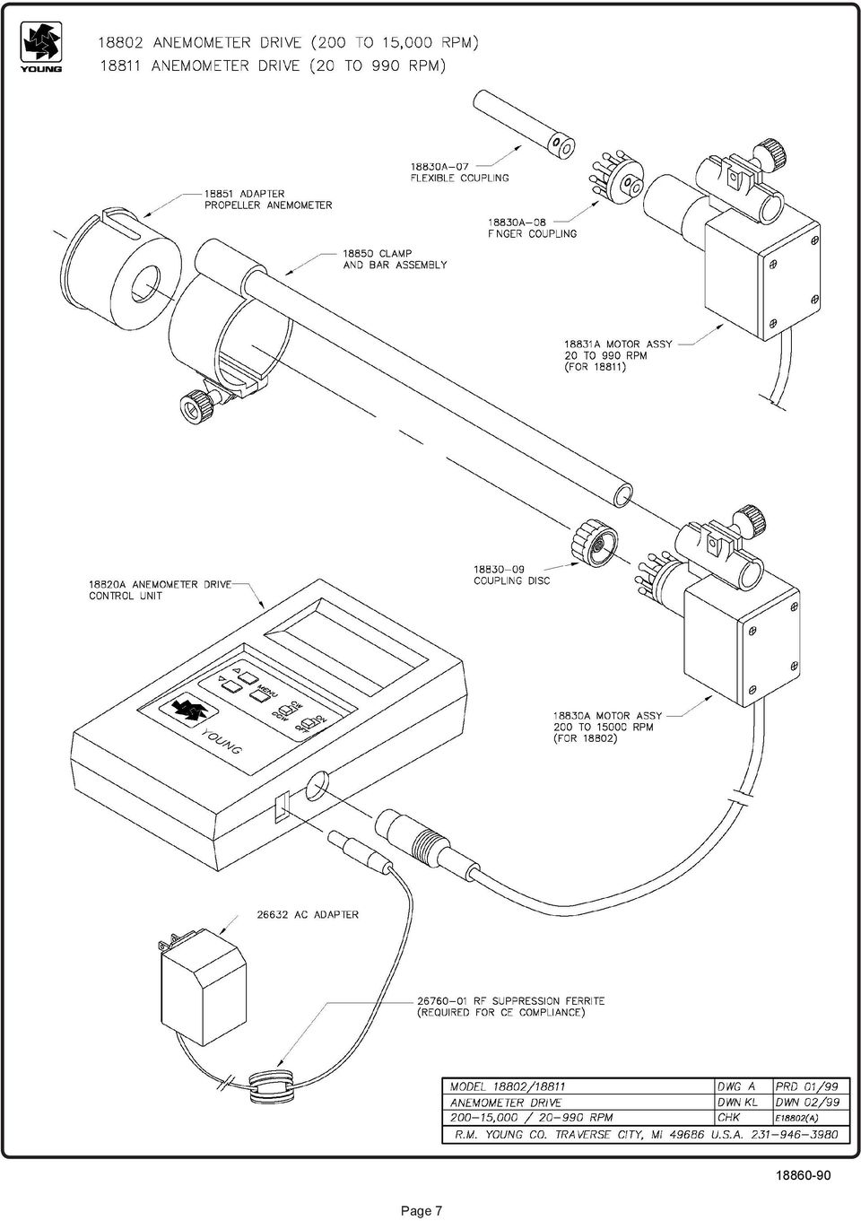
6 MODEL 18802/18811 SELECTABLE SPEED ANEMOMETER DRIVE OPERATION For proper operation, the coupling on the motor must be carefully aligned with the anemometer shaft. Misalignment, particularly at low RPM rates, causes instability and stalling. Alignment fixtures included with the device allow the motor to be attached directly to YOUNG anemometers. Attach the alignment fixture to the sensor as follows: 1) Remove propeller or cup-wheel from anemometer shaft and attach coupling disc to shaft. 2) Mount clamp and bar fixture on sensor and gently tighten clamp. Do not overtighten! 3) Attach motor to fixture. Carefully align anemometer and motor coupling and gently tighten motor clamp. DO NOT OVERTIGHTEN. 4) Turn unit ON and use the UP-DOWN keys to set target RPM. 5) Within several seconds display should show actual RPM within ± 1 RPM of target setting. If not, carefully adjust alignment until display shows proper value. This can be performed while motor is running. If the calibrating unit is used with an anemometer which does not fit the alignment fixture, the motor may be held in place by hand. Good results can be achieved if the motor and anemometer shafts are well aligned. SPECIFICATIONS Operating Range: ,000 RPM (18802) RPM (18811) Resolution: 1 RPM (18802) 0.1 RPM (18811) Power Requirement: 12 to 30 VDC (2W nominal, 6W max) Battery Power: Two 9-V INTRODUCTION MENU Access the Setup Menu by pressing and holding the MENU key for about five seconds. The motor will stop and the Setup Menu will appear on the display. Each menu item and its function is listed below. Use the UP-DOWN keys to scroll between items on the menu list. To EDIT a value, press the MENU key then use the UP-DOWN keys to change it. When you are finished editing, press MENU again. To return to OPERATE mode, repeatedly press the UP key until OPERATE appears on the display then press MENU. The stores the new settings and within several seconds will begin operating at its lowest speed. You MUST return to OPERATE mode to retain new settings. MENU ITEM DESCRIPTION The YOUNG Selectable Speed Anemometer Drive provides a convenient and accurate way to rotate an anemometer shaft at a known rate. The device consists of a control/display unit and a variable speed motor with integral high-resolution optical encoder. Two models are available: Model has an operating range of 200 to 15,000 RPM for use with propeller type anemometers. Model has a lower RPM range for use with cup type anemometers. The control unit is the same in each case. High and low speed motors are available separately, permitting operation in both speed ranges with a single display unit. The control unit automatically senses motor assembly type (high or low speed) and adjusts display and controlling circuits automatically. Operating parameters for each motor type include MAX & MIN RPM, STEP SIZE, and 9 PRESET speeds. Settings for these parameters are saved when power is off. A front panel CW-CCW switch selects rotation direction (as seen facing anemometer). Motor speed is selected using the UP-DOWN keys. The display shows the target and actual RPM. Motor rotation and measurement are referenced to a crystal oscillator for stability and accuracy. Current limiting circuits protect the motor from damage due to overload or stalling. The is powered from an AC wall adapter (included). For completely portable operation, two internal 9-V batteries power the unit. Use lithium type for longest life. When batteries are low, the controller stops the motor and alerts the user on the display. OPERATE MAX RPM MIN RPM STEP SIZE PRESET PRESET1-9 Press MENU to return to OPERATE mode. You MUST return to OPERATE mode to retain new settings. Maximum RPM allowed during operation. Once the maximum is reached, pressing the UP key has no effect. Limited to operating range of motor. Minimum RPM allowed during operation. Once the minimum is reached, pressing the DOWN key has no effect. Limited to operating range of motor. The number of RPM added or subtracted when the UP-DOWN keys are pressed to change target RPM during operation. YES/NO determines whether preset RPM settings are used. If YES, pressing the UP-DOWN keys selects preset speeds 1 through 9. If NO, UP-DOWN changes speed by STEP SIZE increments. Preset RPM values. Each PRESET may be set to any value in operating range of motor. Page 5
 Mount clamp and bar fixture on sensor and gently tighten clamp. Do not overtighten! 3) Attach motor to fixture. Carefully align anemometer and motor coupling and gently tighten motor clamp.")
7 WARRANTY This product is warranted to be free of defects in materials and construction for a period of 12 months from date of initial purchase. Liability is limited to repair or replacement of defective item. A copy of the warranty policy may be obtained from R. M. Young Company. CE COMPLIANCE This product has been tested and shown to comply with European CE requirements for the EMC Directive. Declaration of Conformity R. M. Young Company 2801 Aero Park Drive Traverse City, MI USA Model ANEMOMETER DRIVE The undersigned hereby declares on behalf of R. M. Young Company that the above-referenced product, to which this declaration relates, is in conformity with the provisions of: Council Directive 2004/108/EC (December 15, 2004) on Electromagnetic Compatibility David Poinsett R&D Manager Page 6

8 Page 7
9 Page 8

10 R. M. YOUNG COMPANY TYPICAL TORQUE VALUES For Checking Anemometer Bearing and Transducer Condition 1 New Instrument 2 Max torque for threshold of: Instrument (Standard Models) Sensor Transducer Torque Threshold 0.5 m/s 1.0 m/s gm-cm m/s gm-cm gm-cm Wind Sentry Anemometer AC Coil Wind Monitor AC Coil Wind Monitor - MA AC Coil Wind Monitor - AQ AC Coil Wind Monitor - RE AC Coil Wind Monitor - SE AC Coil Wind Monitor - AQ - SE AC Coil Cup Anemometer 12170C 2400 mv Tach-Gen D Cup Anemometer 12170C Photo Chopper Propeller Anemometer mv Tach-Gen T Propeller Anemometer mv Tach-Gen Photo Chopper NOTES: 1. New instrument torque and threshold specifications are maximum values 2. Values shown are maximum torque to maintain instrument threshold at or below 0.5 m/s and 1.0 m/s respectively. 3. EPA and NRC instrument specifications designate 0.5 m/s wind speed starting threshold. ASTM D "Standard Test Method for Determining the Performance of a Cup Anemometer or Propeller Anemometer" defines "starting threshold" and outlines a method for its determination. SENSORS: Wind Sentry 75 cm Cup Wheel Assembly X 30 cm Polypropylene Propeller (PP) X 30 cm Carbon Fiber Thermoplastic Propeller (CFT) X 30 cm Expanded Polystyrene Propeller (EPS) 12170C 100 cm Cup Wheel Assembly STANDARD BEARINGS: Model Wind Monitor / Wind Monitor-SE : Double Teflon seals & lubricated with M-28 low torque grease Model Wind Monitor - MA : Double Teflon seals & lubricated with "Sta-lube" waterproof grease. All other models : Double metal shields & lubricated with LOI instrument oil Page 9

11 Page 10

12 Page 11

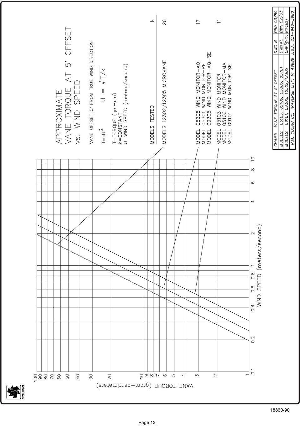
13 R. M. YOUNG COMPANY TYPICAL TORQUE VALUES For Checking Anemometer Bearing and Transducer Condition 1 New Instrument 2, 3 Max torque for threshold of: Instrument (Standard Models) Torque Threshold gm-cm 10 gm-cm gm-cm Wind Monitor Wind Monitor - MA Wind Monitor - AQ Wind Monitor - RE Wind Monitor - SE Wind Monitor - AQ - SE /5 Microvane NOTES: 1. New instrument torque and threshold specifications are maximum values 2. Values shown are maximum torque permitted to maintain instrument threshold at or below 0.5 m/s and 1.0 m/s respectively at 10 displacement. 3. EPA and NRC instrument specifications designate windvane threshold measurement at 10 displacement from equilibrium position. ASTM D Standard Test Method for Determining the Dynamic Performance of a Wind Vane defines starting threshold and outlines a method for its determination. STANDARD BEARINGS: Models Wind Monitor / Wind Monitor-MA / Wind Monitor-SE: Double Teflon seals lubricated with LY-48 wide temperature range grease Models Wind Monitor-AQ / Wind Monitor-RE / Wind Monitor-AQ-SE: Double metal shields lubricated with LOI instrument oil All other models - Double Teflon seals lubricated with LOI instrument oil Page 12

14 Page 13
15 Page 14

16 Page 15
Installation Guide. WSD-100 Wind Speed and Direction Sensor For XR5 Data Loggers. February, 2011
 WSD-100 Wind Speed and Direction Sensor For XR5 Data Loggers Installation Guide February, 2011 Pace Scientific Inc www.pace-sci.com Tel: 704-799-0688 sales@pace-sci.com 1 Disclaimer The following warranty
METEOROLOGICAL INSTRUMENTS
 METEOROLOGICAL INSTRUMENTS INSTRUCTIONS ULTRASONIC ANEMOMETER MODEL 85000 R.M. YOUNG COMPANY 2801 AERO PARK DRIVE, TRAVERSE CITY, MICHIGAN 49686, USA TEL: (231) 946-3980 FAX: (231) 946-4772 WEB: www.youngusa.com
Operating instructions
 Operating instructions Torque transducer type AE with replaceable strain gauge measuring element Model TQ 505 Operating instructions no. 1079 Torque Transducer TQ 505 Page 1 / 16 1. Contents 1. List of
Contactless Encoder RI360P0-QR24M0-INCRX2-H1181
 Compact, rugged housing Many mounting possibilities Status displayed via LED Immune to electromagnetic interference 1024 pulses per revolution (default) 360, 512, 1000, 1024, 2048, 2500, 3600, 4096, parametr.
D.C. Motors. Products and specifications subject to change without notice.
 D.C. Motors Order/Technical Support - Tel: (8) 677-5 / FAX: (8) 677-865 / www.crouzet-usa.com / DC Motors Selection guide Gearbox Speed Torque max (Nm).5. Type of Gearbox 8 8 8. Power usable (w) Torque
DMX-K-DRV. Integrated Step Motor Driver + (Basic Controller) Manual
 Manual") DMX-K-DRV Integrated Step Motor Driver + (Basic Controller) Manual DMX-K-DRV Manual page 1 rev 1.33 COPYRIGHT 2007 ARCUS, ALL RIGHTS RESERVED First edition, June 2007 ARCUS TECHNOLOGY copyrights this document.
DMX-K-DRV Integrated Step Motor Driver + (Basic Controller) Manual DMX-K-DRV Manual page 1 rev 1.33 COPYRIGHT 2007 ARCUS, ALL RIGHTS RESERVED First edition, June 2007 ARCUS TECHNOLOGY copyrights this document.
How To Use Maximum
 DURABLE VERSATILE TECHNICALLY PRECISE MAXIMUM COMMERCIAL INSTRUMENTS Innovative Solutions for Measurement and Control of Weather-Sensitive Equipment Maximum commercial instruments have proven to be effective
Series 6000 Torque measured metal bellow coupling
 Properties Free of float metal bellow coupling with integrated torque measurement Non-contact measurement system, high robustness High torsional stiffness Limited torque of inertia Performance Measurement
SX460. Generator Automatic Voltage Regulator Operation Manual
 SX460 Generator Automatic Voltage Regulator Operation Manual Self Excited Automatic Voltage Regulator Compatible with Newage SX460* * Use for reference purpose only and not a genuine Newage product. 1.
Model SRMD Setra Remote Monitoring Display
 Model SRMD Setra Remote Monitoring Display 1.0 GENERAL INFORMATION Thank you for purchasing the Setra Remote Monitoring Display (SRMD). The SRMD is a digital panel meter with a bright 1 LED display for
Harmonic Drive acutator P r e c i s i o n G e a r i n g & M o t i o n C o n t r o l
 D C S e r v o S y s t e m s RH Mini Series Total Motion Control Harmonic Drive acutator P r e c i s i o n G e a r i n g & M o t i o n C o n t r o l Precision Gearing & Motion Control DC SERVO ACTUATORS
Sense it! Connect it! Bus it! Solve it! EncoderS
 Sense it! Connect it! Bus it! Solve it! EncoderS Incremental encoders Incremental encoders use electrical pulses to measure rotation speed or position. The dual-channel incremental encoders of the Ri series,
Borstlösa DC-motorer. Promoco Scandinavia AB
 Borstlösa DC-motorer Promoco Scandinavia AB BL Series Brushless DC Motors with Integral Drive 24, 54, 68, and 70 mm diameters, 2W up to 110W output power Allied Motion s BL series of small brushless DC
DC Electronic Loads 8500 series
 Data Sheet DC Electronic Loads 8500 series 2400W 600 W - 1200 W 300 W Versatile & Economical DC Electronic Loads The 8500 series Programmable DC Electronic Loads can be used for testing and evaluating
AUTOMATED, FULL LOAD MOTOR TESTING AT PRODUCTION SPEEDS
 AUTOMATED, FULL LOAD MOTOR TESTING AT PRODUCTION SPEEDS Abstract: Revolutionary test method coupled with innovative automation yields superior motor performance measurement data without sacrifice of production
Vaisala Weather Transmitter WXT510 The Most Essential of Weather
 Vaisala Weather Transmitter WXT510 The Most Essential of Weather The Vaisala Weather Transmitter WXT510 makes building weather stations easier than ever. It combines decades of experience and the latest
CONNECTOR AMPLIFIER FOR PROPORTIONAL VALVES (4-20 ma Input Version)
") TECHNICAL DATASHEET #TD1102AX CONNECTOR AMPLIFIER FOR PROPORTIONAL VALVES (4-20 ma Input Version) Part Number: Connector Amplifier CAPV-H-4-20MA-x complete with cable CAPV-4C-yM Where: x = current output
TECHNICAL DATASHEET #TD1102AX CONNECTOR AMPLIFIER FOR PROPORTIONAL VALVES (4-20 ma Input Version) Part Number: Connector Amplifier CAPV-H-4-20MA-x complete with cable CAPV-4C-yM Where: x = current output
WEATHER STATION FOR SOLAR FARM MONITORING
 WEATHER STATION FOR SOLAR FARM MONITORING SOLAR FARM MONITORING SYSTEM: Measures global, horizontal, & background irradiance. Measures wind speed, wind direction, ambient temperature, and relative humidity.
Mounting Instructions. Torque Transducer. A0329 3.2 en
 Mounting Instructions Torque Transducer T5 T5 Contents 3 Page Safety instructions.............................................. 4 1 Measuring characteristics..................................... 7 2 Mounting.....................................................
Pocket Tach 99 (PT99) Non-Contact Tachometer
 Non-Contact Tachometer") CE DECLARATION OF CONFORMITY As Manufacturer: Monarch Instrument Division of Monarch International Inc. 15 Columbia Drive, Amherst NH 03031 USA declares under Monarch s sole responsibility that the product:
CE DECLARATION OF CONFORMITY As Manufacturer: Monarch Instrument Division of Monarch International Inc. 15 Columbia Drive, Amherst NH 03031 USA declares under Monarch s sole responsibility that the product:
Speed Control Methods of Various Types of Speed Control Motors. Kazuya SHIRAHATA
 Speed Control Methods of Various Types of Speed Control Motors Kazuya SHIRAHATA Oriental Motor Co., Ltd. offers a wide variety of speed control motors. Our speed control motor packages include the motor,
DRTS 33. The new generation of advanced test equipments for Relays, Energy meters, Transducers and Power quality meters
 The new generation of advanced test equipments for Relays, Energy meters, Transducers and Power quality meters Testing all relay technologies: electromechanical, solid state, numerical and IEC61850 Manual
22.302 Experiment 5. Strain Gage Measurements
 22.302 Experiment 5 Strain Gage Measurements Introduction The design of components for many engineering systems is based on the application of theoretical models. The accuracy of these models can be verified
Vert-X 16-5V / 10...90% Ub. Applications Servodrives Dancer arm Operating table
 Version MH-C MH-C2 Electrical data Measuring range 0... 360 - Indep. linearity % meas. range ±0.3 - Max. hysteresis 0.1 - Resolution bit 12 - Max. repeatability 0.1 - Sample rate fast mode khz (5) - Sample
APPENDIX A. Bay Area Air Quality Management District
 APPENDIX A Bay Area Air Quality Management District Meteorological Monitoring Guidance for Manual of Procedures, Volume VI: Air Monitoring Procedures (Adopted July 20, 1994) (Latest Revision March 21,
ABB Drives. User s Manual. Pulse Encoder Interface Module RTAC-01
 ABB Drives User s Manual Pulse Encoder Interface Module RTAC-0 Pulse Encoder Interface Module RTAC-0 User s Manual 3AFE 64486853 REV A EN EFFECTIVE:.5.00 00 ABB Oy. All Rights Reserved. Safety instructions
How To Power A Schen
 Automation / Mini Type SCH32F Hollow Shaft Encoder - Ø 32 mm Hollow Bore: Ø 6 mm to Ø 3/8 inch Resolution up to 5000 ppr IP 65 (IP 50 for IDC connector option) Electrical Specifications Code: Resolution:
Model RPM10 Laser Photo / Contact Tachometer with IR Thermometer Patented
 User's Guide Model RPM10 Laser Photo / Contact Tachometer with IR Thermometer Patented Introduction Congratulations on your purchase of Extech's Laser Photo/Contact Tachometer with Non- Contact IR Thermometer,
Material: Weight: Bearing Life: Shaft Speed: Starting Torque: Mass Moment of Inertia: Shaft Loads:
 Automation / Mini Type SCH32F Hollow Shaft Encoder - Ø 32 mm Hollow Bore: Ø 6 mm to Ø 3/8 inch Resolution up to 5000 ppr IP 65 (IP 50 for IDC connector option) Electrical Specifications Code: Resolution:
Multi-Range Programmable DC Power Supplies 9115 Series
 Data Sheet Multi-Range Programmable DC Power Supplies 1200 W / 3000 W Multi-Range DC Power Supplies Features & Benefits Any model can replace several supplies on your bench or in your rack. Unlike conventional
Model EC5111 Speed Controller Isochronous / Droop
 R Conforms to EC Directive on Electromagnetic Compatibility ADVANT ANTAGE SERIES Quality System Certification Model EC5111 Speed Controller Isochronous / Droop Features Isochronous or Droop governing Rugged,
Drayton Digistat +2RF/+3RF
 /+3RF Programmable Room Thermostat Wireless Model: RF700/22090 Model: RF701/22092 Power Supply: Battery - Thermostat Mains - Digistat SCR Invensys Controls Europe Customer Service Tel: 0845 130 5522 Customer
NUCLEAR MAGNETIC RESONANCE. Advanced Laboratory, Physics 407, University of Wisconsin Madison, Wisconsin 53706
 (revised 4/21/03) NUCLEAR MAGNETIC RESONANCE Advanced Laboratory, Physics 407, University of Wisconsin Madison, Wisconsin 53706 Abstract This experiment studies the Nuclear Magnetic Resonance of protons
THERMAL ANEMOMETRY ELECTRONICS, SOFTWARE AND ACCESSORIES
 TSI and TSI logo are registered trademarks of TSI Incorporated. SmartTune is a trademark of TSI Incorporated. THERMAL ANEMOMETRY ELECTRONICS, SOFTWARE AND ACCESSORIES IFA 300 Constant Temperature Anemometry
User Manual. Humidity-Temperature Chart Recorder. Model RH520
 User Manual Humidity-Temperature Chart Recorder Model RH520 Introduction Congratulations on your purchase of the Extech RH520 Temperature + Humidity Chart Recorder. The RH520 measures and displays Temperature,
Duct Humidity Transmitter
 SDC-H Duct Humidity Transmitter Features Replaceable sensor element Humidity measurement for air ducts Minimum and maximum value memory 0 0V, 0 0mA or 0V, 4 0mA measuring signals selectable with jumpers
Current Probes. User Manual
 Current Probes User Manual ETS-Lindgren L.P. reserves the right to make changes to any product described herein in order to improve function, design, or for any other reason. Nothing contained herein shall
Subminiature Load Cell Model 8417
 w Technical Product Information Subminiature Load Cell 1. Introduction... 2 2. Preparing for use... 2 2.1 Unpacking... 2 2.2 Using the instrument for the first time... 2 2.3 Grounding and potential connection...
LDG M-7700 External Meter for Icom IC-7700
 M-7700 OPERATIONS MANUAL MANUAL REV A LDG M-7700 External Meter for Icom IC-7700 LDG Electronics 1445 Parran Road St. Leonard MD 20685 Phone: 410-586-2177 Fax: 410-586-8475 ldg@ldgelectronics.com www.ldgelectronics.com
Mercury TM 1500P PCB-Mount Digital Encoders
 Mercury TM 1500P PCB-Mount Digital Encoders Factory Set Resolution to 0.50μm Reflective Linear and Rotary Encoders Sensor the size of a Dime Resolution Factory Set: x4, x8, x20, or x40 Linear: 5μm, 2.5μm,
OPERATING MANUAL. Table of contents. 2 Phase Stepping Motor Driver 2M542. Rev. A. Introduction page 2. Specifications page 2 Timing chart page 3
 2 Phase Stepping Motor Driver 2M542 OPEATING MANUAL Table of contents Introduction page 2 Specifications page 2 Timing chart page 3 Setting page 4 Current set page 4 educe current function page 4 Micro
Speed Control Relays SX2
 SX2 File 850 CONENS Description.....................................................Page General Information................................................ 2-3 SX2DV General Information...........................................
Pin & Vee Block Test Machine
 Pin & Vee Block Test Machine Picture of the apparatus Used in Standard Test Methods ASTM Standards D 2670, D2626, D3233, D5620 Federal Test Methods FTM-791-3807.1, FTM-791-3812.1 Chrysler Corporation 461-C-84-01,
Series 7500 Torque Sensor
 Properties PTO (Power Take-Off) shaft with integrated torque and angle measurement Non-contact measurement system, high robustness Plug & Play solution, no additional electronics required Performance Measurement
Temperature & Humidity SMS Alert Controller
 Temperature & Humidity Alert Controller METERS 3 simple steps starting the unit: Insert the SIM card Plug in the sensors connectors Connect the AC power cord. Specifications: AC 90~260V Auto Select Internal
Length measuring instruments
 INTERNATIONAL OIML R 66 RECOMMENDATION Edition 1985 (E) Length measuring instruments Instruments mesureurs de longueurs OIML R 66 Edition 1985 (E) ORGANISATION INTERNATIONALE DE MÉTROLOGIE LÉGALE INTERNATIONAL
Reaction Torque Sensor
 Force 1 1 N m up to 1 000 1 000 N m Type 9329A 9389A These easy to install piezoelectric reaction torque sensors are particularly suitable for measuring rapidly changing torques at non-rotating shafts.
MDC151-024031 Series
 MDC151-024031 Series 24V, 3A Brushless DC Controller User s Guide A N A H E I M A U T O M A T I O N 910 East Orangefair Lane, Anaheim, CA 92801 e-mail: info@anaheimautomation.com (714) 992-6990 fax: (714)
CruzPro VAF110. AC Volts, Amps, Frequency, kw Monitor
 CruzPro VAF110 AC Volts, Amps, Frequency, kw Monitor Table of Contents Introduction............................ 3 Specifications........................... 4 Installation..............................5
Position Transducers with Restoring Spring 10, 25, 50, 75, 100 mm TR, TRS Series
 Position Transducers with Restoring Spring 10, 25, 50, 75, 100 mm TR, TRS Series Special features long life 100 x 10 6 movements outstanding linearity up to ±0.075% choice of plug or cable connection DIN
QR12 (1.22 ) Diameter Optical Encoder
 Diameter Optical Encoder") Improving the Quality of Life through the Power in Light QPhase QR12 (1.22 ) Diameter Optical Encoder Design Features: Low profile assembled height of Bearing design simplifies encoder attachment Resolutions
Improving the Quality of Life through the Power in Light QPhase QR12 (1.22 ) Diameter Optical Encoder Design Features: Low profile assembled height of Bearing design simplifies encoder attachment Resolutions
Instructions Manual. Electromagnetic sensor Series FLOMID FX. instrumentation for fluids. R-MI-FlomidFX Rev.: 0 English version
 instrumentation for fluids Electromagnetic sensor Series FLOMID FX Instructions Manual! Conforms with the Pressure Equipment Directive 97/23/EC. 0830 This equipment is considered as being a pressure accessory
Tipping Bucket Rain Gauge Models 6011-A 6011-B
 Tipping Bucket Rain Gauge Models 6011-A 6011-B User s Manual 1165 National Drive Sacramento, CA 95834 800.824.5873 Table of Contents General Information... 1 Introduction... 1 Installation General... 2
Tool Turrets and Tool Discs
 Our other products Automatic Tool Changer Chucking Cylinders Tool Discs Indexing Tables Tool Turrets and Tool Discs Pragati Automation Pvt. Ltd. 1, IV Phase, 11th Cross, Peenya Industrial Area Bangalore
Laserlyte-Flex Alignment System
 Laserlyte-Flex Alignment System LaserLyte-Flex The LaserLyte-Flex Alignment System is a unique, interchangeable, low cost plug and play laser system. Designed specifically for aligning and positioning
Linear Parameter Measurement (LPM)
") (LPM) Module of the R&D SYSTEM FEATURES Identifies linear transducer model Measures suspension creep LS-fitting in impedance LS-fitting in displacement (optional) Single-step measurement with laser sensor
(LPM) Module of the R&D SYSTEM FEATURES Identifies linear transducer model Measures suspension creep LS-fitting in impedance LS-fitting in displacement (optional) Single-step measurement with laser sensor
MEMBRANE VACUUM MINI PUMPS
 MEMBRANE VACUUM MINI PUMPS The mini pumps described in this page are membrane-type. They can be used both as vacuum pumps and compressors. In the latter version they can supply compressed air 100% oil-free
User's Manual. Model 461995 Laser Photo / Contact Tachometer. Introduction
 User's Manual Model 461995 Laser Photo / Contact Tachometer Laser Photo/ Contact Tachometer 461995 MEMORY rpm PHOTO CONTACT ft/min m/min Introduction Congratulations on your purchase of Extech's Laser
Analogue + IVS Electronic Throttle Controls for CUMMINS Engines
 Electronic Throttle Controls for Engines Technical description: Page 2 of 20 The Electronic Throttle Controls have been developed to match the signal required to operate the Modules CM400, CM500 and CM800
Instruction Manual FL
 3. Operation Overview The most common used features (such as displaying force, peak hold, zero and changing of displayed units) can all be done by pressing a single dedicated key identified on the front
Data Sheet. Electro-mechanical counters Hengstler 800 series
 Data Pack D Issued March 00 504897 Data Sheet Electro-mechanical counters Hengstler 800 series The 800 series totalising and predetermining batch counters, manufactured by Hengstler, is available from
Why a torque measuring system?
 T-Sense P R O D U C T B U L L E T I N 660 Optical Torque Measuring Systems Introduction The use of a T-Sense torque measuring system means efficiency improvement, overload protection and prevention of
Physical Specifications (Custom design available.)
") Helmholtz Coils A useful laboratory technique for getting a fairly uniform magnetic field, is to use a pair of circular coils on a common axis with equal currents flowing in the same sense. For a given
Helmholtz Coils A useful laboratory technique for getting a fairly uniform magnetic field, is to use a pair of circular coils on a common axis with equal currents flowing in the same sense. For a given
User's Guide. Digital Viscotesters. Model 345060 High Range (0.3 to 4000 dpas) Model 345055 Low Range (1.5 to 330 mpas) Introduction
 Model 345055 Low Range (1.5 to 330 mpas) Introduction") User's Guide Digital Viscotesters Model 345060 High Range (0.3 to 4000 dpas) Model 345055 Low Range (1.5 to 330 mpas) Introduction Congratulations on your purchase of the Extech Digital Viscotester. The
User's Guide Digital Viscotesters Model 345060 High Range (0.3 to 4000 dpas) Model 345055 Low Range (1.5 to 330 mpas) Introduction Congratulations on your purchase of the Extech Digital Viscotester. The
Global Water Instrumentation, Inc.
 Global Water Instrumentation, Inc. 11390 Amalgam Way Gold River, CA 95670 T: 800-876-1172 Int l: (916) 638-3429, F: (916) 638-3270 Water Level Sensor: WL400 00-997 11/30/09-1 - Congratulations on your
Lab 14: 3-phase alternator.
 Lab 14: 3-phase alternator. Objective: to obtain the no-load saturation curve of the alternator; to determine the voltage regulation characteristic of the alternator with resistive, capacitive, and inductive
PowerAmp Design. PowerAmp Design PAD135 COMPACT HIGH VOLATGE OP AMP
 PowerAmp Design COMPACT HIGH VOLTAGE OP AMP Rev G KEY FEATURES LOW COST SMALL SIZE 40mm SQUARE HIGH VOLTAGE 200 VOLTS HIGH OUTPUT CURRENT 10A PEAK 40 WATT DISSIPATION CAPABILITY 200V/µS SLEW RATE APPLICATIONS
TECHNICAL DATASHEET #TD1404AX PWM CONTROLLED SOLENOID DRIVER
 TECHNICAL DATASHEET #TD1404AX PWM CONTROLLED SOLENOID DRIVER (PWM Input, 1.2A or 2A Output, Metal Box or PCB) PCB Board - P/N: PWMC-PCB-2A, PWMC-PCB-1.2A Packaged Driver (metal box with 1.5 m (5 ft.) cable)
BLWR23MDA Series. 24V, 15A Brushless Controller / Motor. User s Guide. 910 East Orangefair Lane, Anaheim, CA 92801 e-mail: info@anaheimautomation.
 BLWR23MDA Series 24V, 15A Brushless Controller / Motor User s Guide A N A H E I M A U T O M A T I O N 910 East Orangefair Lane, Anaheim, CA 92801 e-mail: info@anaheimautomation.com (714) 992-6990 fax:
A.V.R. R250. Installation and maintenance R250 0V E+ E- VOLT STAB FREQ. & L.A.M. CONFIG. 50Hz. 47.5Hz. 57Hz LAM 1 13% 2 25% OFF LAM OFF 9
 110 0V E+ E- VOLT STAB KNEE 47.5Hz OFF 9 SPECIAL 8 KNEE 65Hz 7 OFF KNEE 6 57Hz OFF 7 8 50Hz o 9 0 5 6 1 2 3 4 OFF 1 13% 2 25% 3 OFF 4 13% 5 25% 60Hz FREQ. & L.A.M. CONFIG. This manual concerns the alternator
Shaft grounding. Carbon brushes for shaft grounding are used in turbo-generators, in distinct AC- and DC motors and as a special application in Ships.
 "Modern AC-Motors don't need carbon brushes and are maintenance free " Until some years ago this thrilling statement could be heard from motor OEM's. Nowadays SCHUNK supplies carbon brushes and brush holders
Problem / Solution. The problem:
 Problem / Solution Solar Photovoltaic (PV) technology has shown significant development in recent years and this has led to many UK homeowners investing in Solar PV installations. Solar electricity is
Hand-held thermometer Model CTH7000
 Calibration technology Hand-held thermometer Model CTH7000 WIKA data sheet CT 55.50 Applications Precision thermometer for very accurate temperature measurements in a range of -200... +962 C Reference
IFC 070 Technical Datasheet
 IFC 070 Technical Datasheet Electromagnetic signal converter Battery driven with low energy consumption Quick and easy to install and operate External data logger and GSM module for remote data transfer
EFC 3600. Frequency converters
 2 Bosch Rexroth AG Electric Drives and Controls Documentation Compact and complete: space saving side-by-side assembly, plug-in I/O terminals, with brake chopper and mains filter for ultra-simple installation
Description. Dimensions. Features. www.pwb-encoders.com. precision works better
 Description The MEC22 is a high resolution optical hollow shaft encoder that can be fixed quickly and easily on different sizes of motor shafts. The encoder provides two square wave outputs in quadrature
Bourns Rotary Encoders. Short Form Brochure Revision 2
 Bourns Rotary Encoders Short Form Brochure Revision 2 Introduction Bourns Sensors and Controls Division has continued to expand its encoder product offering with a wide variety of models to support our
Digital Controllers ACTUATOR COMPATABILITY
 Product Specification 36502B DESCRIPTION APECS DPG-21XX-00X Digital Controllers The DPG-21XX-00X digital controller is used primarily to govern diesel or gas fueled engines of generator sets. This microprocessor-based,
C Standard AC Motors
 C Standard AC Standard AC C-1 Overview, Product Series... C-2 Constant... C-9 C-21 C-113 Reversible C-147 Overview, Product Series Constant Reversible Electromagnetic Brake C-155 Electromagnetic Brake
Multi-Range Programmable DC Power Supplies 9115 Series
 Data Sheet 1200 W Multi-Range DC Power Supplies Features & Benefits Any 9115 series model can replace several supplies on your bench or in your rack. Unlike conventional supplies with fixed output ratings,
Experience with taximeters with a look at the corresponding tables
 Experience with taximeters with a look at the corresponding tables Milan Prasil CMI Laboratory of the fundamental metrology V Botanice 4, 150 72 Prague 5 mprasil@cmi.cz Taximeters in EU are subject to
PMP 4000 Series. Druck Amplified Output Pressure Transducers. GE Sensing. Applications. Features
 Features Applications The PMP 4000 Series provides a complete range of high level voltage output pressure transducers offering advanced levels of measurement accuracy, stability and flexibility from a
Precision Miniature Load Cell. Models 8431, 8432 with Overload Protection
 w Technical Product Information Precision Miniature Load Cell with Overload Protection 1. Introduction The load cells in the model 8431 and 8432 series are primarily designed for the measurement of force
Mounting instructions. Acceleration Transducer B12. B 26.B12.10 en
 Mounting instructions Acceleration Transducer B12 B 26.B12.10 en B12 3 Contents Page Safety instructions.............................................. 4 1 Scope of supply..............................................
Lab 8: DC generators: shunt, series, and compounded.
 Lab 8: DC generators: shunt, series, and compounded. Objective: to study the properties of DC generators under no-load and full-load conditions; to learn how to connect these generators; to obtain their
Adding Pneumatic Preset Counter. Type 497. Continuously visible preset Integrated pneumatic reset 3 or 5-digit display Convenient button setting
 Adding Pneumatic Preset Counter Type 497 Continuously visible preset Integrated pneumatic reset 3 or 5-digit display Convenient button setting VARIABLE PILOT SIGNAL Using two pneumatic preset counters
INSTRUCTION MANUAL for UNIBLITZ MODEL DM412 SHUTTER DRIVE MODULE
 INSTRUCTION MANUAL for UNIBLITZ MODEL DM412 SHUTTER DRIVE MODULE VINCENT ASSOCIATES 803 LINDEN AVE. ROCHESTER, NEW YORK 14625 SERVICE/ORDERS (800) 828-6972 In NY State (585) 385-5930 Fax (585) 385-6004
Servo Info and Centering
 Info and Centering A servo is a mechanical motorized device that can be instructed to move the output shaft attached to a servo wheel or arm to a specified position. Inside the servo box is a DC motor
Typical Aluminum GFM Mass Flow Meter
 MASS FLOW METERS Design Features n Rigid metallic construction. n Maximum pressure of 1000 psig (70 bars). n Leak integrity 1 x 10⁻⁹ of helium. n NIST traceable certification. n Built-in tiltable LCD readout.
By Authority Of THE UNITED STATES OF AMERICA Legally Binding Document
 By Authority Of THE UNITED STATES OF AMERICA Legally Binding Document By the Authority Vested By Part 5 of the United States Code 552(a) and Part 1 of the Code of Regulations 51 the attached document has
AD425S Automatic door operator
 EC8666 Statement Automatic Door Operator is a reliable and quiet door opening and closing device. This product is ideal for enabling access to areas for people with disabilities or simply for convenience
Digital input modules
 8 172 TX-I/O Digital input modules TXM1.8D TXM1.16D Two fully compatible versions: TXM1.8D: 8 inputs, each with a three-color LED (green, yellow or red) TXM1.16D: As TXM1.8X, but 16 inputs, each with a
Three Channel Optical Incremental Encoder Modules Technical Data
 Three Channel Optical Incremental Encoder Modules Technical Data HEDS-9040 HEDS-9140 Features Two Channel Quadrature Output with Index Pulse Resolution Up to 2000 CPR Counts Per Revolution Low Cost Easy
UNIVERSITY OF WATERLOO ELECTRICAL & COMPUTER ENGINEERING DEPARTMENT ME269 ELECTROMECHANICAL DEVICES AND POWER PROCESSING.
 UNIVERSITY OF WATERLOO ELECTRICAL & COMPUTER ENGINEERING DEPARTMENT ME269 ELECTROMECHANICAL DEVICES AND POWER PROCESSING. Group # First Name Last Name UserID @uwaterloo.ca Experiment #3: DIRECT CURRENT
Pump Specifications 405 Series Commercial Drain Pump (High-Temp) 2 Solids handling
 2 Solids handling") Pump Specifications 405 Series Commercial Drain Pump (High-Temp) 2 Solids handling 405_P1 R1/27/2012 Copyright 2012 Liberty Pumps Inc. All rights reserved. Specifications subject to change without notice.
Pump Specifications 405 Series Commercial Drain Pump (High-Temp) 2 Solids handling 405_P1 R1/27/2012 Copyright 2012 Liberty Pumps Inc. All rights reserved. Specifications subject to change without notice.
1000 Series Data Loggers PRODUCT MANUAL
 1000 Series Data Loggers PRODUCT MANUAL Model s 1650, 1525, 1450, 1425, 1400, 1250, 1225, 1200 CONTENTS General Overview 3 Model Specifications 4 External Sensors 5 Installation and Placement 6 Digital
Multimeter measurements on variable frequency drives using the new Fluke 289 DMM
 Multimeter measurements on variable frequency drives using the new Fluke 289 DMM Application Note Editor s note: For similar instructions using the Fluke 87V DMM, reference Fluke article 12345. In the
Solar Tracking Application
 Solar Tracking Application A Rockwell Automation White Paper Solar trackers are devices used to orient photovoltaic panels, reflectors, lenses or other optical devices toward the sun. Since the sun s position
BLOOD COLLECTION MIXER
 USER S MANUAL BLOOD COLLECTION MIXER Model CM735 No. CAT.CM73522Ce Centron Technologies Corporation 319-25 Sadang-4-dong, Dongjak-ku Seoul, Korea 156-823 Tel. +82-2.522.7807 Fax +82-2.522.7806 Table of
EVAL-UFDC-1/UFDC-1M-16
 Evaluation Board for Universal Frequency-to- Digital Converters UFDC-1 and UFDC-1M-16 EVAL-UFDC-1/UFDC-1M-16 FEATURES Full-Featured Evaluation Board for the Universal Frequency-to-Digital Converters UFDC-1