INSTRUCTION MANUAL for UNIBLITZ MODEL DM412 SHUTTER DRIVE MODULE
|
|
|
- Lenard McKenzie
- 9 years ago
- Views:
Transcription
1 INSTRUCTION MANUAL for UNIBLITZ MODEL DM412 SHUTTER DRIVE MODULE VINCENT ASSOCIATES 803 LINDEN AVE. ROCHESTER, NEW YORK SERVICE/ORDERS (800) In NY State (585) Fax (585) A Division of VA, Inc. Version
 385-5930 Fax (585) 385-6004 A Division of VA,")
2 INTRODUCTION The DM412 Drive Module interfaces the smallest aperture shutter in the UNIBLITZ line, the UHS1T2 High Speed Shutter, to the VMM-D1 or VMM-T1 shutter driver units. Operation of the DM412 is simple and straightforward. All activate functions are supplied through the VMM-D1 or VMM-T1 shutter drivers. The only control integral to the DM412 is the NORM\HIGH switch, which allows on-the-fly selection between the normal (NORM) and the (HIGH) speed modes. The CONTROL BNC allows TTL (active low) or remote switch (710R) to electronically select the normal and high-speed modes, providing greater flexibility. MAINTENANCE Although the stability of the timing and drive voltage is assured and calibrated prior to shipment, it may become necessary to make some minor adjustments to the operating systems of the DM412 and the VMM-T1 or VMM-D1 over time. It is highly recommended that if you suspect a problem with your unit that it be returned to the factory for proper adjustments and calibration. The units complicated circuitry will be damaged and/or not function as specified if adjusted improperly. Proper care and maintenance of the unit should be taken as with any electronic instrument. WARRANTY Great care has been taken to ensure that our products are free from defect when shipped. Defective units will be replaced or repaired at no charge, excepting transportation charges, if returned within 90 days from the date of shipment. Vincent Associates will consider the return of unused equipment if returned within 30 days from the date of shipment subject to a 20% restocking charge. This offer does not apply to used or damaged equipment. 2
 or remote switch (710R) to electronically select the normal and high-speed modes, providing greater flexibility.")
3 SPECIFICATIONS Shutter Drive Output (9-Pin Female) Continuously variable frequency o exposures from DC to the shutter s maximum value. Maximum peak pulse power 325W, pulse voltage 65VDC, and pulse current 5A. The DM412 contains two internal drive circuits with the same power spec. Controller Input (7-Pin Male) +65VDC high voltage and VDC low voltage power input from VMM-D1 or VMM-T1 controller. Input trigger control and synchronization return amplifier is also provided from the VMM-D1 or VMM-T1 controller. Control Input (BNC) Power Indicator Power Requirements Fuse Requirements Input impedance 10K ohms. Active low. Source current 500µA. Minimum delay time required to ensure mode switching prior to shutter activation 10msec. Red LED indicates when power is applied. Power provided from VMM-D1 or VMM-T1 Controller. See Controller Input specifications. 5x20mm 800mA slow blow fuse for shutter actuator coil protection. Two required, one for each shutter coil. Size (HWD) (43.63mm) x (90.37mm) x (80.77mm) with black textured finish. See dwg. #L Cables (included) Cable (optional) #910C - interconnect cable for UHS1T2 High Speed Shutter. #702C - interconnect cable for DM412 Shutter Drive Module. #710R - remote trigger cable. 3

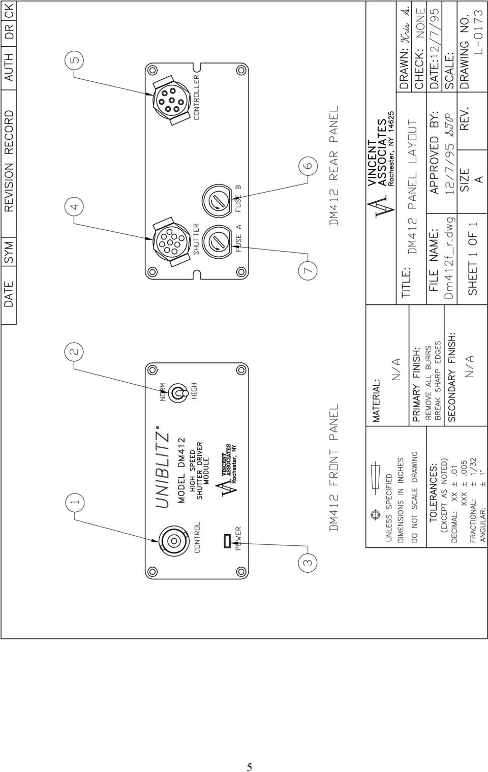
4 DM412 FRONT AND REAR PANEL OPERATOR CONTROLS DESCRIPTION (Refer to Drawing #L-0173) 1. CONTROL INPUT. BNC active low input. Electrically switches the DM412 between the HIGH and NORMAL speed modes. A low level input places the unit into the NORMAL speed mode. A high level places the unit back to the HIGH speed mode. 2. NORM/HIGH Switch. Allows manual switching between the HIGH and NORMAL speed modes. 3. POWER Indicator. 4. SHUTTER. DM412 9-Pin female connector to mate with 9-Pin male connector of the 10 shutter interconnect cable provided with the control. 5. CONTROLLER. DM412 7-Pin male connector to mate with 7-Pin female connector of the 10 interconnect cable provided with the VMM-D1 or VMM- T1 controller. This cable provides power and control for the DM412 control unit. 6. FUSE B. Replace with 5x20mm 800mA slow blow fuse. 7. FUSE A. Replace with 5x20mm 800mA slow blow fuse. 4

5 5
6 OPERATING INSTRUCTIONS After unpacking unit, inspect for any defects. If upon inspection a problem is found, notify Vincent Associates immediately. After initial inspection, the unit is ready for use. Please read the following operating instructions. Improper input/output connections to the unit may cause irreparable damage. The DM412 receives power from VMM-D1 or VMM-T1 driver. Connect the DM412 as per drawing #L Follow the power up procedure as described in the VMM- D1/VMM-T1 users manual. Once power is on, the DM412 POWER LED will illuminate. Place the NORM/HIGH switch in the NORM position. Place the N.O./N.C. switch (of the VMM-D1 or VMM-T1) to the N.O. position. The shutter will open and remain open until either the N.O./N.C. switch is returned to the N.C. position or the NORM/HIGH switch is returned to the HIGH position. Note, the SYNC LED and the SHUTTER LED (of the VMM-D1 or VMM-T1) will illuminate when the shutter goes to the open position to indicate the presence of a shutter activate signal and that the shutter has opened respectively. In the HIGH-speed mode, a signal to the VMM-D1 or VMM-T1 will trigger the UHS1T2 for 300µsec. only. The shutter cannot be held open in this mode. For example, with the DM412 in the HIGH mode, switching the N.O./N.C. switch to the N.O. position the shutter will open for 300µsec. (typical A - G time). The SHUTTER LED of the VMM-D1 or VMM-T1 will illuminate, however, the SYNC LED will only flash indicating a high-speed exposure. Please note, the typical shutter timing for each of the modes respectively is enumerated in the attached UHS1 data sheet. When operating the UHS1 shutter from a pulse source (through the VMM-T1 or VMM- D1) the minimum pulse width, in the NORM mode, is 600µsec. If the input pulse width in this mode is set to less than 600µsec., the shutter response will be indeterminate. If the input pulse is greater than 600µsec., the shutter will be held open for the duration of the pulse and therefore, in this mode, is programmable. Please note, though the minimum input pulse in the NORM mode is 600µsec., the shutter response (A - G window time) will typically be1.0msec (see UHS1 data sheet for typical timing data). In the HIGH speed mode the shutter exposure is 300µsec (proper exposure pulses are derived within the DM412), regardless of the duration of the input pulses to the VMM-D1 or VMM-T1. Therefore, the minimum input pulse or trigger width, input to the VMM-D1 or VMM- T1, will be as enumerated in the SPECIFICATIONS section of the VMM-D1 or VMM-T1 manual. Please review the Caution section on page #21 in the VMM-D1/VMM- T1 manual for information concerning fuse inspection and replacement. The UHS1 can be operated as any typical shutter in the NORM speed mode. Therefore, the shutter can also be controlled via the RS-232 interface. Please review SYSTEMS OPERATIONS section on page #22 in the VMM-D1/VMM-T1 manual. 6
 to the N.O. position. The shutter will open and remain open until either the N.O./N.C. switch is returned to the N.")
7 7

8 8

9 1mm diameter aperture Fastest shutter in the UNIBLITZ line of electroprogrammable shutters. 300µsec. total exposure time in the (HIGH) speed mode. 100µsec. rise time. Activated by an electronic pulse through shutter driver module, the DM412, included. Exposure repetition rate continuously variable from DC-400Hz. Non-resonant design allows instantaneous changes in repetition rate and duty cycle in the normal (NORM) mode. No optical surface when open provides 100% transmittance The UHS1 supersedes the LS2 as the fastest shutter in Vincent s UNIBLITZ line. As with the LS series, the UHS1 is specially suited for laser use, with applications including low level chopping, high speed switching, pulse gating and selection, and modulation to 400 Hz. In the high speed mode (HIGH) the UHS1 produces a total exposure pulse of 300µsec! This speed is unprecedented in Vincent type instrumentation shutters. In the normal speed mode (NORM) the shutter is programmable, and activated by an electronic pulse generated by Vincent s drive module, the DM412. This module is included with the UHS1, and will interface with the D122 and T132 controllers. The DM412 converts the specialized shutter drive outputs into the voltage pulses necessary for proper operation of the UHS1. DM412 Drive Module: Operation of the DM412 is simple and straightforward. All activate functions are supplied through the D122 or T132 shutter drivers. The only controls integral to the DM412 are the NORM/HIGH switch which allows on the fly selections between the normal (NORM) and high (HIGH) speed modes. The CONTROL BNC allows TTL (active low) or remote switch (710R) to electronically select the normal and high speed modes, providing greater flexibility. Standard unit (DM412 included) UHS1T2 COIL RES. PULSE VOLTAGE TO OPEN HOLD VOLT. 12 ohms* +65VDC* +5VDC* * (each actuator) WGT. CASED SHUTTER Typical timing values (msec.) using UNIBLITZ drive equipment and measured with UNIBLITZ shutters equipped with standard TEFLON coated TYPICAL PULSE INPUT TO CONTROLLER SHUTTER STATE TYPICAL ELECTRONIC SYNCHRONIZATION OUTPUT FROM CONTROLLER OPERATING TEMP. ABSOLUTE MAX. FREQUENCY OF OPERAT. TIMING OF PULSE INPUT AND SYNCHRONIZATION OUTPUT RELATIVE TO SHUTTER STATE HIGH NORM O-A Delay time on opening after current is applied A-C Transfer time on opening O-C Total opening time B-F Min. equivalent exp. time C-E Min. dwell time with min. input pulse NUMBER BLADES 4.3 oz. (.121 Kg.) 0 C to +80 C 400Hz. 2 For dimension layout to the Ls2/3/6 SHUTTER SPECIFICATIONS sheet FIGURE 1 and FIGURE 2. E-G Transfer time on closing A-G Total window time MET: Min. exposure time TEP: Typical exposure pulse N/A >1.58 The question regarding enhancement of shutter speed with the application of user supplied lubricants has been repeatedly asked. It is our experience that lubricating the shutter blades will actually slow the shutter down and eventually render the shutter inoperable. UNDER NO CIRCUMSTANCES SHOULD ANY TYPE OF LUBRICANT BE APPLIED TO THE SHUTTER BLADE AREA. (Coated blades, future availability) Due to our ongoing product development program, Vincent Associates reserves the right to discontinue or change specifications or designs at any time, without incurring any obligations. Teflon is a registered trade mark of E.I. Dupont U. S. Pat. No ; ; Drawing shown for illustrative purposes only. 11/02 - Printed in U.S.A 803 Linden Ave., Rochester, NY Tel (585) Fax (585) [email protected] 9

User Manual UNIBLITZ. 14-0020 Version 1.35 2001. VMM-D1 Shutter Driver and VMM-T1 Shutter Driver/Timer
 User Manual UNIBLITZ VMM-D1 Shutter Driver and VMM-T1 Shutter Driver/Timer 14-0020 Version 1.35 2001 1 Vincent Associates products are covered by U.S. patents. Information in this publication supercedes
Technical data. General specifications. Indicators/operating means. 30 Hz Multiplex operation 30 Hz / n, n = number of sensors, n 5
 Model Number Single head system Features Parameterization interface for the application-specific adjustment of the sensor setting via the service program ULTRA 000 programmable switch outputs Hysteresis
Research RF Sputtering Packages
 Research RF Sputtering Packages Shown with 3" Polaris Adjustable Position Source with Tilt and Shutter 300 or 600 Watt Low Cost Packages for Those With Limited Budgets Desiring Full Capability 13.56 MHz
EC4.8. BalancedReferencePreamplifier. Owner smanual ENG
 EC4.8 BalancedReferencePreamplifier Owner smanual ENG Unpacking the EC 4.8 Immediately upon receipt of the EC 4.8, inspect the carton for possible damage during shipment. The carton and packaging have
F(t) Forssell Technologies Inc
 Forssell Technologies Inc") F(t) Forssell Technologies Inc SMP-2Aa Microphone Preamplifier User Manual Forssell Technologies Inc Sandpoint Idaho USA (208) 263-0286 Introduction The Forssell Technologies Inc SMP-2A is a 2 channel,
F(t) Forssell Technologies Inc SMP-2Aa Microphone Preamplifier User Manual Forssell Technologies Inc Sandpoint Idaho USA (208) 263-0286 Introduction The Forssell Technologies Inc SMP-2A is a 2 channel,
DUAL%CHANNEL BROADBAND%LINEAR%AMPLIFIER Model&A800D
 ELECTRONICS AB DUAL%CHANNEL BROADBAND%LINEAR%AMPLIFIER Model&A800D & HIGH&VOLTAGE& FIXED&GAIN& BROADBAND & 800Vpp&60mA& 100x& DC&to&ca&200&kHz & LOW&OUTPUT&IMPEDANCE& HIGH&SLEW&RATE &
PERF10 Rubidium Atomic Clock
 Owner s Manual Audio Stanford Research Systems Revision 1.0 February, 2011 2 Certification Stanford Research Systems certifies that this product met its published specifications at the time of shipment.
±15 V Current-Limited Power Supply
 USER S GUIDE ±15 V Current-Limited Power Supply Model 0901 Newport Corporation 3635 Peterson Way Santa Clara, CA 95054 www.newport.com/newfocus Warranty Newport Corporation guarantees its products to be
Laser diffuse reflection light scanner with background suppression. Dimensioned drawing
 Specifications and description HRTL 3B Laser diffuse reflection light scanner with background suppression Dimensioned drawing We reserve the right to make changes DS_HRTL3B_en.fm en 01-2010/12 50114049
Current Probes. User Manual
 Current Probes User Manual ETS-Lindgren L.P. reserves the right to make changes to any product described herein in order to improve function, design, or for any other reason. Nothing contained herein shall
9448 Installation and User Guide
 9448 Installation and User Guide Compatible Equipment 9040 Internal Sounder 660 Speech communicator 496327 Issue 1 1 of 6 9448 INTRODUCTION The 9448 is a 3 zone control panel with separate Entry/Exit and
ZMR 80 STEREO MODULAR ZONER USERS MANUAL
 ZMR 80 STEREO MODULAR ZONER USERS MANUAL Lime Technologies http://limetechnologies.co.uk Tel: 08712 233127 ZMR80 Stereo Modular Zoner Mixer Introduction The modular construction of the ZMR80 allows it
PSU-U-24V/AC-6A/10/FTA-TR-MC PSAC 0624
 PSU-U-24V/AC-6A/10/FTA-TR-MC PSAC 0624 v.1.0 AC/AC power supply unit Edition: 1 from 24 th October 2008 Supercedes edition: ---------- 10062009 CONTENTS: 1. Technical description. 1.1. General description
OMNIYIG. .5 TO 2 GHz, 1 TO 4 GHz, 6 to 18 GHz Thin Film YIG-TUNED OSCILLATORS OUTLINE DIMESIONS MOUNTING SURFACE GND +15V + TUNE - HTR HTR
 . TO Hz, 1 TO Hz, to 1 Hz Thin Film YITUNED OSCILLATORS Highly Reliable StateoftheArt ThinFilm Technology s. to 1 Hz oscillators employ thinfilm technology, coupled with aas FET transistors, and were designed
APSYN420A/B Specification 1.24. 0.65-20.0 GHz Low Phase Noise Synthesizer
 APSYN420A/B Specification 1.24 0.65-20.0 GHz Low Phase Noise Synthesizer 1 Introduction The APSYN420 is a wideband low phase-noise synthesizer operating from 0.65 to 20 GHz. The nominal output power is
Software Manual RS232 Laser Merge Module. Document # SU-256521-09 Rev A
 Laser Merge Module Document # SU-256521-09 Rev A The information presented in this document is proprietary to Spectral Applied Research Inc. and cannot be used for any purpose other than that for which
Line Level Converter Box. S Class Signal Processors
 Line Level Converter Box S Class Signal Processors Table Of Contents Introduction and Features 3 Front and Rear Panel Layout 4 Operating the S convert Using the LEVEL controls 5 Typical Set-up 6 Wiring
USER MANUAL Stand Alone Power Supply PSQ 2909 / PSQ 3909 / PSQ 4909 PSQ 2920 / PSQ 3920 / PSQ 4920
 USER MANUAL Stand Alone Power Supply PSQ 2909 / PSQ 3909 / PSQ 4909 PSQ 2920 / PSQ 3920 / PSQ 4920 [This page intentionally left blank] Warning for Your Protection 1. Read these instructions. 2. Keep these
PS 155 WIRELESS INTERCOM USER MANUAL
 PS 155 INTERFACE TO SIMPLEX WIRELESS INTERCOM USER MANUAL Issue 2011 ASL Intercom BV DESIGNED AND MANUFACTURED BY: ASL INTERCOM BV ZONNEBAAN 42 3542 EG UTRECHT THE NETHERLANDS PHONE: +31 (0)30 2411901
Switch Selection Guide
 Switch Selection Guide FREQUENCY RANGE (GHz) 0.1 0.2 0.5 1 2 4 8 12.4 18 40 0.1 18 SWITCHES WITH INTEGRATED DRIVERS MODEL OR SERIES PAGE REFLECTIVE SPST SWITCHES* DM86, FM86 DM86H, FM86H 1 18 F91 0.2 4
ECD 2 High Performance Balanced DAC. 24 Bit /192kHz. Owner's Manual
 ECD 2 High Performance Balanced DAC 24 Bit /192kHz Owner's Manual EN Unpacking the ECD 2 Immediately upon receipt of the ECD 2, inspect the carton for possible damage during shipment. If the carton is
INSTRUCTION MANUAL MODEL PCD-88
 INSTRUCTION MANUAL MODEL PCD-88 CLOSED CAPTION DECODER LINK ELECTRONICS, INC. 2137 Rust Avenue Cape Girardeau, Missouri 63703 Phone: 573-334-4433 Fax: 573-334-9255 e-mail: sales @ linkelectronics.com website:
Digital I/O: OUTPUT: Basic, Count, Count+, Smart+
 Digital I/O: OUTPUT: Basic, Count, Count+, Smart+ The digital I/O option port in the 4-Series provides us with 4 optically isolated inputs and 4 optically isolated outputs. All power is supplied externally.
Controller Automation, Model II+
 Controller Automation Page 2 of 2 Automation with the RADAK II+ power controller II+ I/O Points: Inputs 5 Programmable Digital inputs 2 Dedicated digital inputs (Channel select and External SCR control
Agilent 8762/3/4A,B,C Coaxial Switches
 Agilent 8762/3/4A,B,C Coaxial Switches Technical Overview High performance switches for microwave and RF instrumentation and systems Agilent Technologies offers a ver satile line of multiport coaxial switches.
Amplified High Speed Fiber Photodetectors
 Amplified High Speed Fiber Photodetectors User Guide (800)697-6782 [email protected] www.eotech.com Page 1 of 7 EOT AMPLIFIED HIGH SPEED FIBER PHOTODETECTOR USER S GUIDE Thank you for purchasing your Amplified
************* OWNER'S MANUAL BAMF800/2 BAMF1250/2 BAMF1800/2 BAMF2200/2 BAMF2600/2 BAMF1200/4 BAMF1600/4 BAMF2000/1D BAMF4000/1D BAMF5500/1D
 ************* OWNER'S MANUAL BAMF800/2 BAMF1250/2 BAMF1800/2 BAMF2200/2 BAMF2600/2 BAMF1200/4 BAMF1600/4 BAMF2000/1D BAMF4000/1D BAMF5500/1D INTRODUCTION Power Acoustik amplifiers provide high-performance
RS - SPM. Serial parallel translator module
 ReSatron GmbH Boisheimer Str. 162 D-41751 Viersen Telefon (+49) 02162-45 06 80 Telefax (+49) 02162-45 03 04 email: [email protected] RS - SPM Serial parallel translator module RSSPM000215SPM-021 - Subject
CONNECTOR AMPLIFIER FOR PROPORTIONAL VALVES (4-20 ma Input Version)
") TECHNICAL DATASHEET #TD1102AX CONNECTOR AMPLIFIER FOR PROPORTIONAL VALVES (4-20 ma Input Version) Part Number: Connector Amplifier CAPV-H-4-20MA-x complete with cable CAPV-4C-yM Where: x = current output
TECHNICAL DATASHEET #TD1102AX CONNECTOR AMPLIFIER FOR PROPORTIONAL VALVES (4-20 ma Input Version) Part Number: Connector Amplifier CAPV-H-4-20MA-x complete with cable CAPV-4C-yM Where: x = current output
Switch Actuator, 8-fold, 10 A, MDRC AT/S 8.10.1, GH Q631 0075 R0111
 , GH Q631 0075 R0111 The 8-fold switch actuator is a DIN rail mounted device for insertion in the distribution board. It is connected to the EIB via a bus terminal. In the event of bus voltage failure,
BLACK BOX. T1/E1 Link Extenders OCTOBER 2007 MT195A-T1 MT196A-E1
 BLACK BOX NETWORK SERVICES OCTOBER 2007 MT195A-T1 MT196A-E1 T1/E1 Link Extenders Important This is a Class A device and is intended for use in a light industrial environment. It is not intended nor approved
IRT Eurocard. Type DAX-3206. Audio Extractor for 270 Mb/s SDI
 I R T Electronics Pty Ltd A.B.N. 35 000 832 575 26 Hotham Parade, ARTARMON N.S.W. 2064 AUSTRALIA National: Phone: (02) 9439 3744 Fax: (02) 9439 7439 International: 61 2 9439 3744 61 2 9439 7439 Email:
Automatic AES Change-Over
 Automatic AES Change-Over Thank you for choosing a GHIELMETTI product. We are convinced that your choice will prove to be a wise and worthy decision for many years to come. Your GHIELMETTI product has
Brushless DC Motor Controller Product Specification Assembly 025F0129
 Brushless DC Motor Controller Product Specification Assembly 025F0129 September 16, 2009 025F0129 ST B Brushless DC Motor Controller Data Sheet Page 1 Revision History ECN # Date Rev Description By 07058
User Manual PT-E-HIP
 User Manual PT-E-HIP PT-E-HIP User Manual Contents PT-E-HIP-TX Transmitter 1. Introduction 2. How It Connects 3. Features 4. Transmitter Unit Panel Layout PT-E-HIP-RX Receiver 5. Transmitter Unit Panel
FIREDEX 2200. Conventional Fire Panels
 68 Flexible, high specification system Choice of 1, 2, 4 or 8 zones Simple one-shot auto-reset user test facility Approved to EN54 Maintenance free poly switch circuit protection, with auto reset Class
USER MANUAL. Model 6103 3U ForeFront Alarm Card SALES OFFICE (301) 975-1000 TECHNICAL SUPPORT (301) 975-1007. An ISO-9001 Certified Company
 975-1000 TECHNICAL SUPPORT (301) 975-1007. An ISO-9001 Certified Company") USER MANUAL Model 6103 3U ForeFront Alarm Card An ISO-9001 Certified Company Part# 07M6103 Doc# 123011U Rev. A Revised 7/15/03 SALES OFFICE (301) 975-1000 TECHNICAL SUPPORT (301) 975-1007 CONTENTS 1.0
USER MANUAL Model 6103 3U ForeFront Alarm Card An ISO-9001 Certified Company Part# 07M6103 Doc# 123011U Rev. A Revised 7/15/03 SALES OFFICE (301) 975-1000 TECHNICAL SUPPORT (301) 975-1007 CONTENTS 1.0
TOA 900 SERIES II MIXER POWER AMPLIFIER
 Operating Instructions TOA 900 SERIES II MIXER POWER AMPLIFIER A-903MK2 A-906MK2 A-912MK2 TO REDUCE THE RISK OF ELECTRICAL SHOCK, DO NOT REMOVE COVER. NO USER SERVICEABLE PARTS INSIDE. REFER SERVICING
Contents. Safety Warnings... 1
 Contents Safety Warnings... 1 Unpacking the GQ600... 1 Introduction... 2 GQ600 Filter Characteristics... 2 1/3 Octave Centre Frequencies... 4 Front Panel Functions... 5 Rear Panel Functions... 6 Specifications...
User Manual. CFG253 3 MHz Function Generator 070-8362-04
 User Manual CFG253 3 MHz Function Generator 070-8362-04 Copyright Tektronix, Inc. 1993. All rights reserved. Tektronix products are covered by U.S. and foreign patents, issued and pending. Information
TECHNICAL DATASHEET #TD1404AX PWM CONTROLLED SOLENOID DRIVER
 TECHNICAL DATASHEET #TD1404AX PWM CONTROLLED SOLENOID DRIVER (PWM Input, 1.2A or 2A Output, Metal Box or PCB) PCB Board - P/N: PWMC-PCB-2A, PWMC-PCB-1.2A Packaged Driver (metal box with 1.5 m (5 ft.) cable)
Ferrostat Speed Sensor Series DSF Explosion Proof Versions EEx
 Ferrostat Speed Sensor Series DSF Explosion Proof Versions EEx DSF..10.**.HV Ex ATEX Operating Instructions 374E-64368 Valid from lot nr. 0103 General Function Use in potentially explosive environment
To Purchase This Item, Visit BMI Gaming www.bmigaming.com 1-800-746-2255 + 1-561-391-7200. Operation Manual
 Operation Manual 90MAN 01 B Copyright 2008 Patent Pending All Rights Reserved Table of Contents Game Play 3 Game Set up 4 Technical Description 5 Programming 6 10 Error Codes 9 Electronic Components 11
CAUTION! THE 7I29 USES VOLTAGE AND POWER LEVELS THAT REPRESENT A HAZARD TO LIFE AND LIMB.
 7I29 MANUAL Rev 1.5 CAUTION! THE 7I29 USES VOLTAGE AND POWER LEVELS THAT REPRESENT A HAZARD TO LIFE AND LIMB. THE 7I29 IS INTENDED FOR USE BY OEMS THAT WILL INTEGRATE IT INTO A SYSTEM WITH INTERLOCKS AND
DVT913 TV CHANNEL CONVERTER
 Broadband Cable Networks 1(5) DVT913 TV CHANNEL CONVERTER General DVT913 is a TV Channel Converter for the DVX tend product family. It consists of an input down converter from to, a high selectivity part
RF Power Amplifier PA10W Owner s Manual SpinCore Technologies, Inc. http://www.spincore.com
 RF Power Amplifier PA10W Owner s Manual SpinCore Technologies, Inc. http://www.spincore.com Congratulations and thank you for choosing a design from SpinCore Technologies, Inc. We appreciate your business!
Master Time Clock MTC-200 MTC-400 MTC-600. Users Manual
 Master Time Clock MTC-200 MTC-400 MTC-600 Users Manual Toll Free (888)713-0373 Phone (972)987-4408 FAX (877)720-9291 www.midwest-time.com [email protected] TABLE OF CONTENTS TOPIC PAGE GENERAL DESCRIPTION
MASTERSOUND. M a s t e r E m o t i o n. PF 100 Limited. Made in Italy
 MASTERSOUND PF 100 Limited Made in Italy Our Philosophy Our philosophy is simple: we want to produce amplifiers which stimulate the emotions for those who enjoy music. We believe that every piece of music
Instruction Sheet ACS-101. General Description. Specifications. Amplified Broadband UHF Combiner-Splitter. Overall. Antenna Splitter.
 ACS-101 Amplified Broadband UHF Combiner-Splitter General Description The ACS-101 (Antenna Combiner Splitter 10 to 1) is an amplified and filtered broadband splitter-combiner. It allows up to 10 base stations
Product Information Sheet UH28CS-12kV Hi Pot Tester
 Product Information Sheet UH28CS-12kV ETL Prüftechnik GmbH Telefon: +49 711 83 99 39-0 E-Mail: [email protected] Carl-Peters-Straße 23 D-70825 Korntal-Münchingen Telefax: +49 711 83 99 39-9 Internet:
Unattended Answering Device Instruction Manual
 Model 3137B Unattended Answering Device Instruction Manual Monroe Electronics 100 Housel Ave Lyndonville NY 14098 800-821-6001 585-765-2254 fax: 585-765-9330 monroe-electronics.com Printed in USA Copyright
Inductive Proximity Sensors
 M12 Inductive Proximity Sensors Standard Length Mini's Extended Sensing 3 Wire DC 2 Wire DC 2 Wire AC (Wiring Schematic) 3 Wire DC PNP Normally Open (1) IMM32122C IMM35124C IMN32122C IMN35124C IMN32122M12
OPERATING INSTRUCTIONS
 PIPELINE INSPECTION COMPANY LTD. OPERATING INSTRUCTIONS Wet Sponge Holiday Detectors 670,673, and MSRB Wet Sponge Holiday Detectors Portable and In-Plant Detectors Table of Contents General Information.......................3
LOXONE 12 Channel Amplifier
 LOXONE 12 Channel Amplifier Item no.: 200110 Thank you for purchasing the Loxone Twelve Channel Amplifier. The versatility of the Amplifier makes it the perfect choice for almost every type of custom multi-room
RI-215A Operator s Manual. Part Number: 71-0045RK Revision 0 Released: 10/3/05
 RI-215A Operator s Manual Part Number: 71-0045RK Revision 0 Released: 10/3/05 Warranty RKI Instruments, Inc., warrants gas alarm equipment sold by us to be free from defects in materials and workmanship,
Product Information Sheet UH36 Hi Pot Tester
 Product Information Sheet UH36 ETL Prüftechnik GmbH Telefon: +49 711 83 99 39-0 E-Mail: [email protected] Carl-Peters-Straße 23 D-70825 Korntal-Münchingen Telefax: +49 711 83 99 39-9 Internet: www.etl-prueftechnik.de
GAE953 Electrical Alarm Unit 19" with Indicator
 Master Instruction 08.95 MI EIO2211 A-(en) GAE953 Electrical Alarm Unit 19" with Indicator The electrical alarm unit GAE953 gives a signal when one or two set alarm values have been exceeded. Input signals
BROADCAST Trasmettitori / Transmitters DBH3 GAP FILLER
 INTRODUCTION The equipment described here below is a TRANSMITTER that allows to receive a signal coming from satellite, to demodulate it to have the ASI format, to present it into DVB-H standard by a DVB-H
ALARM ANNUNCIATOR ME - 3010 INSTRUCTION MANUAL
 ALARM ANNUNCIATOR ME - 3010 INSTRUCTION MANUAL INTRODUCTION... 2.. TECHNICAL DATA... 3 ACCESSORIES... 5. INSTALLATION... 7 OPERATION... 12. TECHNICAL INFORMATION... 13 MAINTENANCE... 14. CONFIGURATIONS...
2-Pair HDSL1 Adtran Fiber Optic Link System
 ISSUE 2 June 01, 2004 Data Sheet #37 2-Pair HDSL1 Adtran Fiber Optic Link System Contents 1. General. 1 2. Application... 2 3. Housings.. 2 4. Installation 3 5. Provisioning. 5 6. LED Indicators. 6 7.
LDG DTS-4/4R Desktop Coaxial Switch / Remote
 LDG DTS-4/4R Desktop Coaxial Switch / Remote LDG Electronics 1445 Parran Road, PO Box 48 St. Leonard MD 20685-2903 USA Phone: 410-586-2177 Fax: 410-586-8475 [email protected] www.ldgelectronics.com
TS510 & TS500. Installation & User Guide. Compatible Equipment
 Installation & User Guide Compatible Equipment TS510 REM - Remote Keypad 9040 - Loudspeaker DC54/58 - Digital Communicator SD1+ - Speech Dialler 496525 Issue A 1 of 10 TS510 and TS500 Overview Introduction
THERMAL ANEMOMETRY ELECTRONICS, SOFTWARE AND ACCESSORIES
 TSI and TSI logo are registered trademarks of TSI Incorporated. SmartTune is a trademark of TSI Incorporated. THERMAL ANEMOMETRY ELECTRONICS, SOFTWARE AND ACCESSORIES IFA 300 Constant Temperature Anemometry
PSDC 08128. PSDC 12V/8A/8x1A Power supply for up to 8 analog cameras PTC/TOPIC.
 PSDC 08128 v.1.2 PSDC 12V/8A/8x1A Power supply for up to 8 analog cameras PTC/TOPIC. EN** Edition: 9 from 25.05.2015 Supersedes the edition: 8 from 12.12.2014 the 8x 1A/12V DC power output for powering
INSTRUCTION MANUAL VRT-200. TECSYSTEM S.r.l. Via Cristoforo Colombo, 5/C 20094 Corsico (MI) phone +39-02 - 48601011 / 4581861 Fax: +39-02 48600783
 phone +39-02 - 48601011 / 4581861 Fax: +39-02 48600783") INSTRUCTION MANUAL VRT-200 TECSYSTEM S.r.l. Via Cristoforo Colombo, 5/C 20094 Corsico (MI) phone +39-02 - 48601011 / 4581861 Fax: +39-02 48600783 http://www.tecsystem.it R.3 27/03/03 VRT200 protection
INSTRUCTION MANUAL VRT-200 TECSYSTEM S.r.l. Via Cristoforo Colombo, 5/C 20094 Corsico (MI) phone +39-02 - 48601011 / 4581861 Fax: +39-02 48600783 http://www.tecsystem.it R.3 27/03/03 VRT200 protection
ViZion Installation Guide
 ViZion Installation Guide v2.0 1 ViZion Installation Guide Table of Contents Inventory Hardware Setup Understanding Synchronization Cable Begin by taking an inventory of the required equipment DR Unit
AMPLIFIED HIGH SPEED FIBER PHOTODETECTOR USER S GUIDE
 AMPLIFIED HIGH SPEED FIBER PHOTODETECTOR USER S GUIDE Thank you for purchasing your Amplified High Speed Fiber Photodetector. This user s guide will help answer any questions you may have regarding the
Ordering Part Numbers: Universal Signal Converter: USC-CVB225-01 Universal Signal Converter with a 4-20mA input and +/- 10V output: USC-CVB225-B10V
 Description: The universal signal converter offers threeway isolation and translates one input control signal into one to three simultaneous outputs. Switches allow the user to select the desired input
F2400 FOM II Series Fiber Optic Modem Technical Manual
 F2400 FOM II Series Fiber Optic Modem Technical Manual T1 Revision B Copyright April 2003 VERSITRON, Inc. 83 Albe Drive / Suite C Newark, DE 19702 www.versitron.com A030430283T PROPRIETARY DATA All data
IPX AUTOMATIC IP NETWORK LOSS BACKUP A/B SWITCH INSTRUCTION BOOK IB6444-02
 IPX AUTOMATIC IP NETWORK LOSS BACKUP A/B SWITCH INSTRUCTION BOOK IB6444-02 TABLE OF CONTENTS DESCRIPTION 2 MOUNTING INSTRUCTIONS 2 HOW TO CABLE THE IPX 2/3 POWER SUPPLY INSTALLATION 3 OPERATION 3 CARE
In-Sight Hardware specifications
 specifications In-Sight 5000, 5100, 5400, 5400S, 5400C, 5401, and 5403 4020 Linz/Austria Pummererstr. 36 Tel.: +43-(0)70-7646-0* www.schmachtl.at Memory Job/Program 16MB non-volatile flash memory; Unlimited
SPECIAL NOTICE. All references to NAT product part numbers (and associated images) are equivalent to AEM product part numbers.
 are equivalent to AEM product part numbers.") SPECIAL NOTICE This product is now licensed to Anodyne Electronics Manufacturing (AEM) from Northern Airborne Technology (NAT). AEM is responsible for all matters related to this product, including sales,
SPECIAL NOTICE This product is now licensed to Anodyne Electronics Manufacturing (AEM) from Northern Airborne Technology (NAT). AEM is responsible for all matters related to this product, including sales,
MISE - STEREO ENCODER
 MISE - STEREO ENCODER 1. FRONT PANEL CONTROLS and INDICATORS AUDIO LEVEL F1 F2 F3 F4 OVER- MOD F5 F1:AUDIO LEVEL Control The setting of this screwdriver adjustment determines the audio input signal level.
VK-250 WARRANTY REGISTRATION FORM
 VK-250 WARRANTY REGISTRATION FORM Unit Serial Number: Customer Name: Address: Date of Purchase: Purchased From: Dealer Name: Address: IMPORTANT NOTE: In order to receive the full five year product warranty,
1.44 kw Programmable DC Power Supplies XLN Series
 Data sheet 1.44 kw Programmable DC Power Supplies XLN Series New Family of High Density System Power Supplies The B&K Precision XLN series are compact, programmable, single-output DC power supplies, suitable
1 All safety instructions, warnings and operating instructions must be read first.
 ONYX USER MANUAL 2 Dateq ONYX Manual Safety instructions EN Safety instructions 1 All safety instructions, warnings and operating instructions must be read first. 2 All warnings on the equipment must be
DCS Input/Output Relay Card Series
 Input/Output Relay Card Series I/O RELAY CARD (with loopback test function) 8N The 8N series I/O Relay Cards easily and quickly standardize and facilitate installation of the relay board. Loopback test
INTEGRATED CIRCUITS. 74LVC08A Quad 2-input AND gate. Product specification IC24 Data Handbook. 1997 Jun 30
 INTEGRATED CIRCUITS IC24 Data Handbook 1997 Jun 30 FEATURES Wide supply voltage range of 1.2 V to 3.6 V In accordance with JEDEC standard no. 8-1A Inputs accept voltages up to 5.5 V CMOS low power consumption
AC/DC Power Modules C B. TML Series, 20 & 40 Watt. Features. 20 Watt Models
 TML Series, 0 & 0 Watt Features C B Scheme LVD UL 090- Encapsulated power supplies with increased power density Replaces TML and TML 0 series PCB mount or chassis mount with screw terminals Single, dual
Inductive sensor NI10-M18-Y1X-H1141
 ATEX category II 1 G, Ex zone 0 ATEX category II 1 D, Ex zone 20 SIL2 as per IEC 61508 Threaded barrel, M18 x 1 Chrome-plated brass DC 2-wire, nom. 8.2 VDC Output acc. to DIN EN 60947-5-6 (NA- MUR) M12
Technical Datasheet Scalar Network Analyzer Model 8003-10 MHz to 40 GHz
 Technical Datasheet Scalar Network Analyzer Model 8003-10 MHz to 40 GHz The Giga-tronics Model 8003 Precision Scalar Network Analyzer combines a 90 db wide dynamic range with the accuracy and linearity
Model 3000-51 20 SPDT Relays 90401460
 Model 3000-51 20 SPDT Relays 90401460 Page 1 All technical data and specifications in this publication are subject to change without prior notice and do not represent a commitment on the part of Giga-tronics,
SFS81 Series. Servo Finishing Stand PUSHCORP, INC. Dallas, Texas
 SFS81 Series Servo Finishing Stand PUSHCORP, INC. Dallas, Texas May, 2012 NEVER OPERATE THE SFS81 MANUALLY NEVER OPERATE THE SFS81 WITH PERSONEL IN THE WORKCELL DO NOT USE LUBRICATED AIR. This device requires
LED...A70..4-..Q Series Sealed High-Intensity
 LED...A70..4-..Q Series Sealed High-Intensity Area Lights High-Power Lighting for use with PresencePLUS and Other Vision Systems Features Rugged, waterproof housing, rated IEC IP68 Compact area light for
How To Use A Cdm250 Digital Multimeter
 User Manual CDM250 Digital Multimeter 070-6736-03 Copyright Tektronix, Inc. 1987. All rights reserved. Tektronix products are covered by U.S. and foreign patents, issued and pending. Information in this
User's Guide. Integrating Sound Level Datalogger. Model 407780. Introduction
 User's Guide 99 Washington Street Melrose, MA 02176 Phone 781-665-1400 Toll Free 1-800-517-8431 Visit us at www.testequipmentdepot.com Back to the Extech 407780 Product Page Integrating Sound Level Datalogger
DMX-K-DRV. Integrated Step Motor Driver + (Basic Controller) Manual
 Manual") DMX-K-DRV Integrated Step Motor Driver + (Basic Controller) Manual DMX-K-DRV Manual page 1 rev 1.33 COPYRIGHT 2007 ARCUS, ALL RIGHTS RESERVED First edition, June 2007 ARCUS TECHNOLOGY copyrights this document.
DMX-K-DRV Integrated Step Motor Driver + (Basic Controller) Manual DMX-K-DRV Manual page 1 rev 1.33 COPYRIGHT 2007 ARCUS, ALL RIGHTS RESERVED First edition, June 2007 ARCUS TECHNOLOGY copyrights this document.
GENERATOR START CONTROL MODULE - MINI (2 Wire to 3 Wire)
") FEATURES & APPLICATIONS Inexpensive 2 wire to 3 wire start controller for electric start high speed gas generators. Optimized for use with Outback Invertors. Supports three types of 3 wire generator control
FEATURES & APPLICATIONS Inexpensive 2 wire to 3 wire start controller for electric start high speed gas generators. Optimized for use with Outback Invertors. Supports three types of 3 wire generator control
ACS-30-EU-EMDR-10-MOD
 Multi-application heat tracing Control and Monitoring in commercial and residential buildings Roof & Gutter de-icing sensor module Technical Information Approvals Module IP rating Ambient operating temperature
Technical Data. back-up time in minutes 100% load 6 7 0 5 6 0 5 0 50% load 15 18 0 15 16 0 15 0
 The protectoq is a On-Line double conversion UPS-system according to IEC / EN 62040-3 (VFI-SS-111) with sinus wave output voltage in each operation mode, LCDindication, RS232 interface, USB-connection,
Innkeeper PBX. Desktop Digital Hybrid. User Guide. JK Audio
 Innkeeper PBX Desktop Digital Hybrid User Guide JK Audio Introduction Innkeeper PBX will allow you to send and receive audio through your multi-line PBX, ISDN or analog telephone. While this may seem like
MS4000/MS4000U Mini-Siren
 MAN MS4000 INSTALL REV: 1/26/01 255331B INSTALLATION AND OPERATING INSTRUCTIONS MS4000/MS4000U Mini-Siren i Section Title Page I General Description...... 1 II Specifications... 2 III Safety Message To
HVA200 High Voltage Amplifier
 HVA200 High Voltage Amplifier Operating Manual Table of Contents Part 1. Important Safety Notice... 3 Part 2. Product Overview... 4 Part 3. Setup and Operation... 5 3.1. HVA200 Controls and Features...
TELIKOU Intercom System. MS-500(4+1 channel) Main Station Instruction Manual
 Main Station Instruction Manual") TELIKOU Intercom System MS-500(4+1 channel) Main Station Instruction Manual TELIKOU Systems All Rights Reserved While TELIKOU makes every attempt to maintain the accuracy of the information contained in
TELIKOU Intercom System MS-500(4+1 channel) Main Station Instruction Manual TELIKOU Systems All Rights Reserved While TELIKOU makes every attempt to maintain the accuracy of the information contained in
zseries 18-Slot Chassis 18-Slot 3U PXI Express Chassis with AC Up to 8 GB/s
 TECHNICAL SPECIFICATIONS zseries 18-Slot Chassis 18-Slot 3U PXI Express Chassis with AC Up to 8 GB/s 2015 LitePoint, A Teradyne Company. All rights reserved. The LitePoint zseries 18-slot chassis is an
User s Manual Before using the inverter, you need to read and save the safety instructions.
 User s Manual Before using the inverter, you need to read and save the safety instructions. STI SERIES (STI200, STI300, STI500, STI700, STI1000) Power Frequency Pure Sine Wave Inverter The information
C220 PRELIMINARY TUBE PREAMPLIFIER SERVICE MANUAL. SERIAL NO. WS1001 And Above C220. Serial Number W S1001 And Above CONTENTS
 Performance Specifications... 2 Notes... 2 Rear Panel... 3 Section Location... 3 Block Diagram... 5-6 Interconnection Diagram... 7-8 Main Schematic and PCB... 9-18 C220 TUBE PREAMPLIFIER CONTENTS Display
SL Series AC and DC Electronic Loads
 SL Series AC and DC Electronic Loads Applications AC & DC Power Supply Testing Rechargeable batteries and chargers Fuel cell test - cells and stacks PFC circuit test Pulsed LED Test and Burn-in Laser Diode
400-800. Series OMEGA WATTS POWER SUPPLY AC/DC SINGLE OR MULTIPLE OUTPUT. Flexible modular design. Programmable outputs** Power factor correction***
 INPUT Input protection Thermal protection Switching frequency internal fuse standard 100KHz Input with PFC : (MML400PFC, MML600, MML800) Input voltage range 85*-264VAC Inrush current (peak) MML400PFC
WD-AMX Water Detection Controllers
 Page 1 of 5 WD-AMX Water Detection Controllers Features: Benefit: LED Status of leak status VFC output Audible alarm Auto or manual reset alarm output Uses an isolated AC signal which prevents oxidation