Adafruit LED Backpacks
|
|
|
- Sheila Fitzgerald
- 9 years ago
- Views:
Transcription
1 Adafruit LED Backpacks Created by lady ada Last updated on :05:32 AM EDT

2 Guide Contents Guide Contents Overview 1.2" 8x8 Matrix ( 8x8 Matrix Software 0.8" 8x8 Matrix Mini 8x8 Matrix Software 0.54" Alphanumeric Attaching the Backpack Attaching Header Prepare the header strip: Add the Backpack: Downloading the Arduino Library Wiring! Load Demo Library Reference ASCII data Writing Data 0.56" 7-Segment Backpack Seven-Segment Backpack Firmware 1.2" 7-segment Backpack Arduino Wiring - R3 and later Arduino Due and Other 3.3v Processors Arduino "Classic" Wiring Seven-Segment Backpack Firmware Bi-Color 8x8 Matrix Bi-Color 8x8 LED Backpack Firmware Schematic Bi-Color 24 Bargraph Attaching the bar-graph modules Soldering on breadboard pins Bi-Color Bargraph LED Backpack Wiring & Firmware Connecting Multiple Backpacks Adafruit Industries Page 2 of 58

3 Wire it Up Configure the Address Changing I2C Address Changing Addresses Changing the address in your code F.A.Q. Downloads Adafruit Industries Page 3 of 58

4 Overview What's better than a single LED? Lots of LEDs! A fun way to make a small display is to use an 8x8 matrix ( or a 4-digit 7-segment display ( Matrices like these are 'multiplexed' - so to control 64 LEDs you need 16 pins. That's a lot of pins, and there are driver chips like the MAX7219 ( that can control a matrix for you but there's a lot of wiring to set up and they take up a ton of space. Here at Adafruit we feel your pain! After all, wouldn't it be awesome if you could control a matrix without tons of wiring? That's where these adorable LED matrix backpacks come in. We have them in quite a few flavors! Adorable Mini 8x8 ( Classic 1.2" 8x8 (round and square dots) ( 4-digit 0.56" 7-segment ( 4-digit 1.2" 7-segment ( 4-digit 0.54" 14-segment Alphanumeric ( Bi-color 8x8 ( Bi-color Bargraph ( Adafruit Industries Page 4 of 58

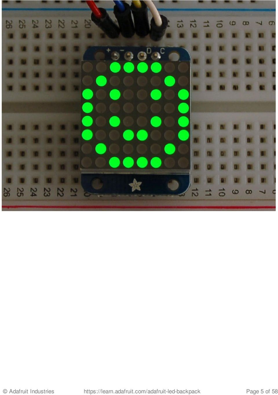
5 Adafruit Industries Page 5 of 58
6 Adafruit Industries Page 6 of 58

7 The matrices use a driver chip that does all the heavy lifting for you: They have a built in clock so they multiplex the display. They use constant-current drivers for ultra-bright, consistant color (the images above are photographed at the dimmest setting to avoid overloading our camera!), 1/16 step display dimming, all via a simple I2C interface. The backpacks come with address-selection jumpers so you can connect up to four mini 8x8's or eight 7-segments (or a combination, such as four mini 8x8's and four 7-segments, etc) on a single I2C bus. The product kit comes with a fully tested and assembled LED backpack, a 4-pin header and the matrix of your choice. A bit of soldering is required to attach the matrix onto the backpack but its very easy to do and only takes about 5 minutes. Of course, in classic Adafruit fashion, we also have a detailed tutorial showing you how to solder, wire and control the display. We even wrote a very nice library for the backpacks so you can get running in under half an hour, displaying images on the matrix or numbers on the 7-segment. If you've been eyeing matrix displays but hesitated because of the complexity, his is the solution you've been looking for! Adafruit Industries Page 7 of 58
 on a single I2C bus.")

8 1.2" 8x8 Matrix This version of the LED backpack is designed for the 1.2" 8x8 matrices. They measure only 1.2"x1.2" so its a shame to use a massive array of chips to control it. This backpack solves the annoyance of using 16 pins or a bunch of chips by having an I2C constant-current matrix controller sit neatly on the back of the PCB. The controller chip takes care of everything, drawing all 64 LEDs in the background. All you have to do is write data to it using the 2-pin I2C interface. There are two address select pins so you can select one of 8 addresses to control up to 8 of these on a single 2-pin I2C bus (as well as whatever other I2C chips or sensors you like). The driver chip can 'dim' the entire display from 1/16 brightness up to full brightness in 1/16th steps. It cannot dim individual LEDs, only the entire display at once. These instruction apply to the 1.2" Matrix only! If you have a Bi-Color or 0.8" square matrix, follow the links on the left side of the page. When you buy a pack from Adafruit, it comes with the fully tested and assembled backpack as well as a 8x8 matrix in one of the colors we provide (say, red, yellow or green). You'll need to solder the matrix onto the backpack but its an easy task. WATCH OUT! THE MATRIX MUST BE INSTALLED THE RIGHT WAY! First look for the line of text on the side of the LED matrix WATCH OUT! THE MATRIX MUST BE INSTALLED THE RIGHT WAY! Find the corner of the backpack with a filled in dot. Make sure that the text on the side of the matrix is on the same side as the filled dot WATCH OUT! THE MATRIX MUST BE INSTALLED THE RIGHT WAY! Slide the matrix into the backpack and flip it over. Triple check that the text is on the same side as the From Adafruit text Adafruit Industries Page 8 of 58
.")

9 Solder in all 16 pins Then clip the matrix leads short Now you're ready to wire it up to a microcontroller. We'll assume you want to use a 4pin header. You can also of course solder wires directly. Place a 4-pin piece of header with the LONG pins down into the breadboard. Place the soldered backpack on top of the header. Solder the four pins That's it! now you're ready to run the firmware! ( 8x8 Matrix Software We wrote a basic library to help you work with the mini 8x8 matrix backpack. The library is written for the Arduino and will work with any Arduino as it just uses the I2C pins. The code is very portable and can be easily adapted to any I2C-capable micro. Wiring to the matrix is really easy Connect CLK to the I2C clock - on Arduino UNO thats Analog #5, on the Leonardo its Digital #3, Adafruit Industries Page 9 of 58

10 on the Mega its digital #21 Connect DAT to the I2C data - on Arduino UNO thats Analog #4, on the Leonardo its Digital #2, on the Mega its digital #20 Connect GND to common ground Connect VCC+ to power - 5V is best but 3V also seems to work for 3V microcontrollers. Next, download the Adafruit LED Backpack library from github ( To download click the DOWNLOADS button in the top right corner, rename the uncompressed folder Adafruit_LEDBackpack. Check that the Adafruit_LEDBackpack folder contains Adafruit_LEDBackpack.cpp and Adafruit_LEDBackpack.h Place the Adafruit_LEDBackpack library folder your arduinosketchfolder/libraries/ folder. You may need to create the libraries subfolder if its your first library. You'll also need to download the Adafruit GFX library ( that provides the graphics drawing routines. Restart the IDE. Once you've restarted you should be able to select the File->Examples->Adafruit_LEDBackpack- >matrix88 example sketch. Upload it to your Arduino as usual. You should see a basic test program that goes through a bunch of different drawing routine Once you're happy that the matrix works, you can write your own sketches. The 8x8 matrix supports everything the Adafruit GFX library - drawing pixels, lines, rectancles, circles, triangles, roundrects, Adafruit Industries Page 10 of 58

 after drawing to 'save' the memory out to the matrix via I2C.")
11 and small bitmaps. For more details check out the GFX page which will detail all of the GFX routines ( All the drawing routines only change the display memory kept by the Arduino. Don't forget to call writedisplay() after drawing to 'save' the memory out to the matrix via I2C. There are also a few small routines that are special to the matrix: setbrightness(brighness)- will let you change the overall brightness of the entire display. 0 is least bright, 15 is brightest and is what is initialized by the display when you start. You can call this function at any time to change the brightness of the -entire- display blinkrate(rate) - You can blink the entire display. 0 is no blinking. 1, 2 or 3 is for display blinking.you can call this function at any time to change the blink rate of the -entire- display The default orientation for graphics commands on this display places pixel (0,0) at the top-left when the header is at the left and Adafruit logo at the right. To use the matrix as shown above (header at top, logo at bottom), call matrix.setrotation(3) before issuing graphics commands. Adafruit Industries Page 11 of 58


12 0.8" 8x8 Matrix This version of the LED backpack is designed for these very cute miniature 8x8 matrices. They measure only 0.8"x0.8" so its a shame to use a massive array of chips to control it. This backpack solves the annoyance of using 16 pins or a bunch of chips by having an I2C constant-current matrix controller sit neatly on the back of the PCB. The controller chip takes care of everything, drawing all 64 LEDs in the background. All you have to do is write data to it using the 2-pin I2C interface. There are two address select pins so you can select one of 4 addresses to control up to 4 of these on a single 2- pin I2C bus (as well as whatever other I2C chips or sensors you like). The driver chip can 'dim' the entire display from 1/16 brightness up to full brightness in 1/16th steps. It cannot dim individual LEDs, only the entire display at once. These instruction apply to the 0.8" Matrix only! If you have a Bi-Color or 1.2" square matrix, follow the links on the left side of the page. When you buy a pack from Adafruit, it comes with the fully tested and assembled backpack as well as a 8x8 matrix in one of the colors we provide (say, red, yellow or green). You'll need to solder the matrix onto the backpack but its an easy task. Remove the parts from packaging and place the LED matrix OVER the silkscreen side. It can go 'either way' - the matrix is symmetric so as long as it goes onto the front it will work in any orientation. Do not solder the matrix over the chip on the back of the backpack - it will not work then! Turn the backpack over so its sitting flat on the matrix. Solder all 16 pins. Adafruit Industries Page 12 of 58
.")

13 Clip the long pins. Now you're ready to wire it up to a microcontroller. We'll assume you want to use a 4pin header. You can also of course solder wires directly. Place a 4-pin piece of header with the LONG pins down into the breadboard. Place the soldered backpack on top of the header. Solder 'em! That's it! now you're ready to run the firmware! Mini 8x8 Matrix Software We wrote a basic library to help you work with the mini 8x8 matrix backpack. The library is written for the Arduino and will work with any Arduino as it just uses the I2C pins. The code is very portable and can be easily adapted to any I2C-capable micro. Wiring to the matrix is really easy Connect CLK to the I2C clock - on Arduino UNO thats Analog #5, on the Leonardo its Digital #3, on the Mega its digital #21 Connect DAT to the I2C data - on Arduino UNO thats Analog #4, on the Leonardo its Digital #2, on the Mega its digital #20 Connect GND to common ground Connect VCC+ to power - 5V is best but 3V also seems to work for 3V microcontrollers. Next, download the Adafruit LED Backpack library from github ( To download click the DOWNLOADS button in the top right corner, rename the uncompressed folder Adafruit_LEDBackpack. Check that the Adafruit_LEDBackpack folder Adafruit Industries Page 13 of 58

14 contains Adafruit_LEDBackpack.cpp and Adafruit_LEDBackpack.h Place the Adafruit_LEDBackpack library folder your arduinosketchfolder/libraries/ folder. You may need to create the libraries subfolder if its your first library. You'll also need to download the Adafruit GFX library ( that provides the graphics drawing routines. Follow the same instructions as above, but with Adafruit_GFX instead of Adafruit_LEDBackpack. Restart the IDE. Once you've restarted you should be able to select the File->Examples->Adafruit_LEDBackpack- >matrix88 example sketch. Upload it to your Arduino as usual. You should see a basic test program that goes through a bunch of different drawing routines Once you're happy that the matrix works, you can write your own sketches. The 8x8 matrix supports everything the Adafruit GFX library - drawing pixels, lines, rectancles, circles, triangles, roundrects, and small bitmaps. For more details check out the GFX page which will detail all of the GFX Adafruit Industries Page 14 of 58

 after drawing to 'save' the memory out to the matrix via I2C.")
15 routines ( All the drawing routines only change the display memory kept by the Arduino. Don't forget to call writedisplay() after drawing to 'save' the memory out to the matrix via I2C. There are also a few small routines that are special to the matrix: setbrightness(brighness)- will let you change the overall brightness of the entire display. 0 is least bright, 15 is brightest and is what is initialized by the display when you start blinkrate(rate) - You can blink the entire display. 0 is no blinking. 1, 2 or 3 is for display blinking. The default orientation for graphics commands on this display places pixel (0,0) at the top-left when the header is at the top and Adafruit logo at the bottom. matrix.setrotation() can be used to use the display in other orientations. Adafruit Industries Page 15 of 58
 - You can blink the entire display. 0 is no blinking. 1, 2 or 3 is for display blinking.")
16 0.54" Alphanumeric ( This version of the LED backpack is designed for two dual 14-segment "Alphanumeric" displays. These 14-segment displays normally require 18 pins (4 'characters' and 14 total segments each) This backpack solves the annoyance of using 18 pins or a bunch of chips by having an I2C constantcurrent matrix controller sit neatly on the back of the PCB. The controller chip takes care of everything, drawing all the LEDs in the background. All you have to do is write data to it using the 2-pin I2C interface. There are three address select pins so you can select one of 8 addresses to control up to 8 of these on a single 2-pin I2C bus (as well as whatever other I2C chips or sensors you like). The driver chip can 'dim' the entire display from 1/16 brightness up to full brightness in 1/16th steps. It cannot dim individual LEDs, only the entire display at once. Attaching the Backpack When you buy a pack from Adafruit, it comes with the fully tested and assembled backpack as well as two dual 14-segment display in one of the colors we provide (say, red, yellow, blue or green). You'll need to solder the matrix onto the backpack but it's an easy task. Remove the parts from packaging and place the LED matrices OVER the silkscreen side. DO NOT PUT THE DISPLAY ON UPSIDE DOWN OR IT WONT WORK!! Check the image Adafruit Industries Page 16 of 58

17 below to make sure the 'decimal point' dots are on the bottom, matching the silkscreen. Remove the parts from packaging and place the LED matrices OVER the silkscreen side. DO NOT PUT THE DISPLAY ON UPSIDE DOWN OR IT WONT WORK!! Check the image below to make sure the 'decimal point' dots are on the bottom, matching the silkscreen. Remove the parts from packaging and place the LED matrices OVER the silkscreen side. DO NOT PUT THE DISPLAY ON UPSIDE DOWN OR IT WONT WORK!! Check the image below to make sure the 'decimal point' dots are on the bottom, matching the silkscreen. Remove the parts from packaging and place the LED matrices OVER the silkscreen side. DO NOT PUT THE DISPLAY ON UPSIDE DOWN OR IT WONT WORK!! Check the image below to make sure the 'decimal point' dots are on the bottom, matching the silkscreen. Turn the backpack over so it is sitting flat on the matrix. Adafruit Industries Page 17 of 58

18 Solder all of the pins! Adafruit Industries Page 18 of 58

19 Adafruit Industries Page 19 of 58

20 Clip the long pins. Adafruit Industries Page 20 of 58


21 Check your work, making sure each pin is nicely soldered, and there's no cold solder joints or shorted pins Attaching Header Prepare the header strip: Cut the strip to length if necessary. It will be easier to solder if you insert it into a breadboard - long pins down Adafruit Industries Page 21 of 58

22 Add the Backpack: Place the backpack board over the pins so that the short pins poke through the breakout pads Solder all 5 pins! That's it! now you're ready to run the firmware on your Arduino! Downloading the Arduino Library We wrote a basic library to help you work with the alphanumeric backpack. The library is written for the Arduino and will work with any Arduino as it just uses the I2C pins. The code is very portable and can be easily adapted to any I2C-capable micro. Begin by downloading our Adafruit LED Backpack library from github ( You can do that by visiting the github repo and manually downloading or, easier, just click this button to download the zip Download LED Backpack Library Rename the uncompressed folder Adafruit_LEDBackpack and check that the Adafruit_LEDBackpack folder contains Adafruit_LEDBackpack.cpp and Adafruit_LEDBackpack.h Place the Adafruit_LEDBackpack library folder your arduinosketchfolder/libraries/ folder. You may need to create the libraries subfolder if its your first library. Restart the IDE. We also have a great tutorial on Arduino library installation at: ( You'll also need to download the Adafruit GFX library - even though this particular backpack doesn't Adafruit Industries Page 22 of 58
23 use it! Its just one of those Arduino dependencies! You can grab the Adafruit GFX library from github ( or download by clicking below. Download Adafruit GFX Library Rename the uncompressed folder Adafruit_GFX and check that the Adafruit_GFX folder contains Adafruit_GFX.cpp and Adafruit_GFX.h Place the Adafruit_GFX library folder your arduinosketchfolder/libraries/ folder like you did with the LED backpacks Wiring! Nex up, let's wire it up to an Arduino. We'll be using an Arduino. Connect CLK to the I2C clock - on Arduino UNO thats Analog #5, on the Leonardo it's Digital #3, on the Mega it's digital #21 Connect DAT to the I2C data - on Arduino UNO thats Analog #4, on the Leonardo it's Digital #2, on the Mega it's digital #20 Connect GND to common ground Connect VCC+ to power - 5V is best but 3V will work if that's all you've got (it will be dimmer) Connect Vi2c to your microcontroller's logic level (3-5V) - If you're using an Arduino, this is almost certainly 5V. If its a 3V Arduino such as a Due, connect it to 3V Both Vi2c and Vcc MUST be connected to 3 to 5VDC! Vcc is for the LED driver power, Vi2c is what sets the logic level for communication to the chip. Adafruit Industries Page 23 of 58
24 Load Demo Restart the Arduino IDE and load up the File->Adafruit_LEDBackpack->quadalphanum demo Adafruit Industries Page 24 of 58


25 Upload to your Arduino, and open up the Serial console at 9600 baud speed. You'll see each digit light up all the segments, then the display will scroll through the 'font table' showing every character that it knows how to display. Finally, you'll get a notice to start typing into the serial console. Type a message and hit return, you'll see it scroll onto the display! Adafruit Industries Page 25 of 58
26 Library Reference For the quad displays, we have a special object that can handle ascii data for easy printing. You can create the object with Adafruit_AlphaNum4 alpha4 = Adafruit_AlphaNum4(); There's no arguments or pins because the backpacks use the fixed I2C pins. By default, the address is 0x70, but you can pass in the I2C address used when you initialize the display with begin alpha4.begin(0x70); // pass in the address Next up, the segments can be turned on/off for each digit by writing the 'raw' bitmap you want, for example, all the LEDs off on digit #3 is alpha4.writedigitraw(3, 0x0); All the segments on for digit #0 is Adafruit Industries Page 26 of 58
; This is the segment map: the 16 bit digit you pass in for raw image has this mapping: 0 DP N M L K J H G2 G1 F E D C B A The first bit isn't used, you can make it 0 or 1 To")
27 alpha4.writedigitraw(0, 0x3FFF); This is the segment map: the 16 bit digit you pass in for raw image has this mapping: 0 DP N M L K J H G2 G1 F E D C B A The first bit isn't used, you can make it 0 or 1 To turn on just the A segment, use 0x0001 To turn on just the G1 segment, use 0x0040 ASCII data If you're just looking to print 'text' you can use our font table, just pass in an ASCII character! For example, to set digit #0 to A call: alpha4.writedigitascii(0, 'A') Writing Data Don't forget to 'write' the data to the display with alpha4.writedisplay(); That's what actually 'sets' the data onto the LEDs! Adafruit Industries Page 27 of 58
 This backpack solves the annoyance of using 13 pins or a bunch of chips by having an I2C constant-current")
28 0.56" 7-Segment Backpack This version of the LED backpack is designed for these big bright 7-segment displays. These 7- segment displays normally require 13 pins (5 'characters' and 8 total segments each) This backpack solves the annoyance of using 13 pins or a bunch of chips by having an I2C constant-current matrix controller sit neatly on the back of the PCB. The controller chip takes care of everything, drawing all the LEDs in the background. All you have to do is write data to it using the 2-pin I2C interface. There are three address select pins so you can select one of 8 addresses to control up to 8 of these on a single 2-pin I2C bus (as well as whatever other I2C chips or sensors you like). The driver chip can 'dim' the entire display from 1/16 brightness up to full brightness in 1/16th steps. It cannot dim individual LEDs, only the entire display at once. When you buy a pack from Adafruit, it comes with the fully tested and assembled backpack as well as a 7-segment display in one of the colors we provide (say, red, yellow, blue or green). You'll need to solder the matrix onto the backpack but it's an easy task. Remove the parts from packaging and place the LED matrix OVER the silkscreen side. DO NOT PUT THE DISPLAY ON UPSIDE DOWN OR IT WONT WORK!! Check the image below to make sure the 'decimal point' dots are on the bottom, matching the silkscreen. Turn the backpack over so it is sitting flat on the matrix. Solder all 14 pins. Adafruit Industries Page 28 of 58

29 Clip the long pins. Now you're ready to wire it up to a microcontroller. We'll assume you want to use a 4pin header. You can also of course solder wires directly. Place a 4-pin piece of header with the LONG pins down into the breadboard. Place the soldered backpack on top of the header and Solder 'em! That's it! now you're ready to run the firmware! Seven-Segment Backpack Firmware We wrote a basic library to help you work with the 7-segment backpack. The library is written for the Arduino and will work with any Arduino as it just uses the I2C pins. The code is very portable and can be easily adapted to any I2C-capable micro. Wiring to the matrix is really easy Connect CLK to the I2C clock - on Arduino UNO thats Analog #5, on the Leonardo it's Digital #3, on the Mega it's digital #21 Connect DAT to the I2C data - on Arduino UNO thats Analog #4, on the Leonardo it's Digital #2, on the Mega it's digital #20 Connect GND to common ground Connect VCC+ to power - 5V is best but 3V also seems to work for 3V microcontrollers. Next, download the Adafruit LED Backpack library from github ( To download click the DOWNLOADS button in the top right corner, rename the uncompressed folder Adafruit_LEDBackpack. Check that the Adafruit_LEDBackpack folder contains Adafruit_LEDBackpack.cpp and Adafruit_LEDBackpack.h Place the Adafruit_LEDBackpack library folder your arduinosketchfolder/libraries/ folder. You may need to create the libraries subfolder if it's your first library. You'll also need to download the Adafruit GFX library ( - rename it Adafruit_GFX and install it as the LED backpack library. It's not actually used for the 7- Adafruit Industries Page 29 of 58
30 segment, it's only for the matrix backpacks but it's still required. Restart the IDE. Once you've restarted you should be able to select the File?Examples?Adafruit_LEDBackpack? sevenseg example sketch. Upload it to your Arduino as usual. You should see a basic test program that goes through a bunch of different routines. Once you're happy that the matrix works, you can write your own sketches. There's a few ways you can draw to the display. The easiest is to just call print - just like you do with Serial print(variable,hex) - this will print a hexidecimal number, from 0000 up to FFFF print(variable,dec) or print(variable) - this will print a decimal integer, from 0000 up to 9999 If you need more control, you can call writedigitnum(location, number) - this will write the number (0-9) to a single location. Location #0 is all the way to the left, location #2 is the colon dots so you probably want to skip it, location #4 is all the way to the right. If you want a decimal point, call writedigitnum(location, number, true) which will paint the decimal point. To draw the colon, usedrawcolon(true or false) Adafruit Industries Page 30 of 58
31 If you want even more control, you can call writedigitraw(location,bitmask) to draw a raw 8-bit mask (as stored in a uint8_t) to that location. All the drawing routines only change the display memory kept by the Arduino. Don't forget to call writedisplay() after drawing to 'save' the memory out to the matrix via I2C. There are also a few small routines that are special to the backpack: setbrightness(brightness)- will let you change the overall brightness of the entire display. 0 is least bright, 15 is brightest and is what is initialized by the display when you start blinkrate(rate) - You can blink the entire display. 0 is no blinking. 1, 2 or 3 is for display blinking. Adafruit Industries Page 31 of 58

32 1.2" 7-segment Backpack These backpacks drive the massive 1.2" 7-segment modules. With 2 leds per segment these make a gorgeous and impressive display. The 7-segment displays normally require 16 pins to drive. This backpack uses an I2C constant-current matrix controller on the back of the PCB, so you only need 2 pins to drive it! The controller chip takes care of multiplexing all the LEDs in the background. All you have to do is write data to it using the 2-pin I2C interface. There are three address select pins so you can select one of 8 addresses to control up to 8 of these on a single 2-pin I2C bus (as well as whatever other I2C chips or sensors you like). The driver chip can 'dim' the entire display from 1/16 brightness up to full brightness in 1/16th steps. It cannot dim individual LEDs, only the entire display at once. When you buy a pack from Adafruit, it comes with the fully tested and assembled backpack as well as a 7-segment display in one of the colors we provide (say, red, yellow, blue or green). You'll need to solder the matrix onto the backpack but its an easy task. Remove the parts from packaging and place the LED matrix OVER the silkscreen side. DO NOT PUT THE DISPLAY ON UPSIDE DOWN OR IT WONT WORK!! Check the image below to make sure the 'decimal point' dots are in the same location as the ones on the silkscreen. Turn the backpack over so its sitting flat on the matrix and ready to solder. Then solder each pin. There are 8 on each end for a total of 16. Adafruit Industries Page 32 of 58

33 That completes the basic assembly. For use on a breadboard, you will want to also install a 5-pin header on the edge of the board. Clip the long pins close to the board. Cut the header strip to length if necessary and insert LONG pins down into the breadboard. Adafruit Industries Page 33 of 58
34 Then solder all 5 pins. Now you are ready to wire it to your microcontroller. The required connections are: "D" - I2C Data Pin (SDA) "C" - I2C Clock Pin (SCL) "+" - 5v. (Will not run on 3.3v!) "-" - GND "IO" - I2C bus voltage. Due to the size of this display, there are 2 LEDs in series for each segment. Because of this, the display requires 5v to run. It will not run on 3.3v. For use with 3.3v processors, connect the IO pin to 3.3v. This will keep the I2C bus signals at a safe level for your processor. With 5v processors like the Arduino UNO, this pin can be connected to either 5v or 3.3v. (use 3.3v if there will be other 3.3v devices on the bus) Arduino Wiring - R3 and later Connect: D -> SDA C -> SCL + -> 5v - -> GND Adafruit Industries Page 34 of 58

35 IO -> jumper to + for 5v. Arduino Due and Other 3.3v Processors Connect: D -> SDA C -> SCL + -> 5v - -> GND IO -> 3.3v Arduino "Classic" Wiring Connect: D -> Analog-4 or Digital 20 for the Mega C -> Analog-5 or Digital 21 for the Mega + -> 5v - -> GND IO -> jumper to + for 5v. OK, now on to the firmware! Seven-Segment Backpack Firmware Our 7-segment backpack library makes it easy to program these displays. The library is written for the Arduino and will work with any Arduino as it just uses the I2C pins. The code is very portable and can be easily adapted to any I2C-capable micro. You can download the Adafruit LED Backpack library from github ( To download click the DOWNLOADS button in the top right corner, rename the uncompressed folder Adafruit_LEDBackpack. Check that the Adafruit_LEDBackpack folder contains Adafruit_LEDBackpack.cpp and Adafruit_LEDBackpack.h. If you need help with installing you libraries, we have a detailed guide here: Installing Arduino Libraries You'll also need to download the Adafruit GFX library ( - rename it Adafruit_GFX and install it as the LED backpack library. Close all open IDE windows and restart the IDE. Adafruit Industries Page 35 of 58
36 Once you've restarted you should be able to select the File?Examples?Adafruit_LEDBackpack? sevenseg example sketch. Upload it to your Arduino as usual. You should see a "sevenseg" example sketch that will demonstrate various capabilities of the library and the display. Once you're happy that the matrix works, you can write your own sketches. There's a few ways you can draw to the display. The easiest is to just call print - just like you do with Serial print(variable,hex) - this will print a hexidecimal number, from 0000 up to FFFF print(variable,dec) or print(variable) - this will print a decimal integer, from 0000 up to 9999 If you need more control, you can call writedigitnum(location, number) - this will write the number (0-9) to a single location. Location #0 is all the way to the left, location #2 is the colon dots so you probably want to skip it, location #4 is all the way to the right. To control the colon and decimal points, use the writedigitraw(location, bitmap) function. Specify 2 for the location and the bits are mapped as follows: 0x02 - center colon 0x04 - left colon - lower dot 0x08 - left colon - upper dot 0x10 - decimal point If you want a decimal point, call writedigitnum(location, number, true) which will paint the decimal Adafruit Industries Page 36 of 58
37 point. To draw the colon, use drawcolon(true or false) If you want full control of the segments in all digits, you can call writedigitraw(location,bitmask) to draw a raw 8-bit mask (as stored in a uint8_t) to anylocation. All the drawing routines only change the display memory kept by the Arduino. Don't forget to call writedisplay() after drawing to 'save' the memory out to the matrix via I2C. There are also a few small routines that are special to the backpack: setbrightness(brighness)- will let you change the overall brightness of the entire display. 0 is least bright, 15 is brightest and is what is initialized by the display when you start blinkrate(rate) - You can blink the entire display. 0 is no blinking. 1, 2 or 3 is for display blinking. Adafruit Industries Page 37 of 58
38 Bi-Color 8x8 Matrix This version of the LED backpack is designed for these bright and colorful square=pixeled 8x8 matrices. They have 64 red and 64 green LEDs inside, for a total of 128 LEDs controlled as a 8x16 matrix. This backpack solves the annoyance of using 24 pins or a bunch of chips by having an I2C constant-current matrix controller sit neatly on the back of the PCB. The controller chip takes care of everything, drawing all 128 LEDs in the background. All you have to do is write data to it using the 2- pin I2C interface. There are three address select pins so you can select one of 8 addresses to control up to 8 of these on a single 2-pin I2C bus (as well as whatever other I2C chips or sensors you like). The driver chip can 'dim' the entire display from 1/16 brightness up to full brightness in 1/16th steps. It cannot dim individual LEDs, only the entire display at once. Pay close attention to the instructions for positioning the matrix. It must be oriented correctly to work and is almost impossible to remove it once it has been soldered to the backpack! Adafruit Industries Page 38 of 58

39 When you buy a pack from Adafruit, it comes with the fully tested and assembled backpack as well as a 8x8 matrix. You'll need to solder the matrix onto the backpack but its an easy task. Remove the parts from packaging and place the LED matrix OVER the silkscreen side. The matrix must be soldered on the correct orientation or it will not work! Check for the side of the matrix that has printing on it. Then look for the front of the PCB that has a circle instead of a square in the corner and line those up as shown on the left Do not solder the matrix over the chip on the back of the backpack - it will not work then! Turn the backpack over so its sitting flat on the matrix. Solder all 24 pins. Clip the long pins Now you're ready to wire it up to a microcontroller. We'll assume you want to use a 4pin header. You can also of course solder wires directly. Place a 4-pin piece of header with the LONG pins down into the breadboard. Adafruit Industries Page 39 of 58

40 Place the soldered backpack on top of the header. Solder 'em! Bi-Color 8x8 LED Backpack Firmware We wrote a basic library to help you work with the bi-color 8x8 matrix backpack. The library is written for the Arduino and will work with any Arduino as it just uses the I2C pins. The code is very portable and can be easily adapted to any I2C-capable micro. Wiring to the matrix is really easy Connect CLK to the I2C clock - on Arduino UNO thats Analog #5, on the Leonardo its Digital #3, on the Mega its digital #21 Connect DAT to the I2C data - on Arduino UNO thats Analog #4, on the Leonardo its Digital #2, on the Mega its digital #20 Connect GND to common ground Connect VCC+ to power - 5V is best but 3V also seems to work for 3V microcontrollers. Next, download the Adafruit LED Backpack library from github ( To download click the DOWNLOADS button in the top right corner, rename the uncompressed folder Adafruit_LEDBackpack. Check that the Adafruit_LEDBackpack folder contains Adafruit_LEDBackpack.cpp and Adafruit_LEDBackpack.h Place the Adafruit_LEDBackpack library folder your arduinosketchfolder/libraries/ folder. You may need to create the libraries subfolder if its your first library. You'll also need to download the Adafruit GFX library ( that provides the graphics drawing routines. Restart the IDE. Once you've restarted you should be able to select the File->Examples->Adafruit_LEDBackpack- >bicolor88 example sketch. Upload it to your Arduino as usual. You should see a basic test program that goes through a bunch of different drawing routines Adafruit Industries Page 40 of 58

41 Once you're happy that the matrix works, you can write your own sketches. The 8x8 matrix supports everything the Adafruit GFX library - drawing pixels, lines, rectangles, circles, triangles, roundrects, and small bitmaps. For more details check out the GFX page which will detail all of the GFX routines ( All the drawing routines only change the display memory kept by the Arduino. Don't forget to call writedisplay() after drawing to 'save' the memory out to the matrix via I2C. There are also a few small routines that are special to the matrix: setbrightness(brightness)- will let you change the overall brightness of the entire display. 0 is least bright, 15 is brightest and is what is initialized by the display when you start blinkrate(rate) - You can blink the entire display. 0 is no blinking. 1, 2 or 3 is for display blinking. The default orientation for graphics commands on this display places pixel (0,0) at the top-left when the header is at the left and Adafruit logo at the right. To use the matrix as shown above (header at top, logo at bottom), call matrix.setrotation(3) before issuing graphics commands. Adafruit Industries Page 41 of 58
42 Schematic Adafruit Industries Page 42 of 58
43 Bi-Color 24 Bargraph This version of the LED backpack is designed for these bright and colorful bi-color bargraph modules. Each module has 12 red and 12 green LEDs inside, for a total of 24 LEDs controlled as a 1x12 matrix. We put two modules on each backpack for a 24-bar long bargraph (48 total LEDs). This backpack solves the annoyance of using lots of pins or a bunch of chips by having an I2C constant-current matrix controller sit neatly on the back of the PCB. The controller chip takes care of everything, drawing all 48 LEDs in the background. All you have to do is write data to it using the 2-pin I2C interface. There are three address select pins so you can select one of 8 addresses to control up to 8 of these on a single 2-pin I2C bus (as well as whatever other I2C chips or sensors you like). The driver chip can 'dim' the entire display from 1/16 brightness up to full brightness in 1/16th steps. It cannot dim individual LEDs, only the entire display at once. Attaching the bar-graph modules Adafruit Industries Page 43 of 58
44 Pay close attention to the instructions for positioning the bargraphs. They must be oriented correctly to work and is almost impossible to remove them once soldered to the backpack! Remove the parts from packaging and place the LED bargraphs over the outlines on the top of the PCB. The bargraph must be soldered on the correct orientation or it will not work! Check for the side of the bargraph that has printing on it. Then look for the outline on the PCB that has "Text on this side" marked! Do not solder the matrix onto the back of the PCB, it won't work either! Adafruit Industries Page 44 of 58

45 To keep the two bargraphs lined up nicely, you can use a little masking or scotch tape on the bargraph modules, tape them so they are in a straight line. There is a little play during soldering so if you don't do this the two modules may not be in a perfect line. Turn over the PCB and bend opposite-corner pins of the modules out so that the modules are fixed in place against the PCB. Now is a good time to do a last check that you oriented the modules the right way! Adafruit Industries Page 45 of 58

46 Solder all the module pins in! OK nice work! Once soldered, clip each pin. They're quite short and the pins are thicker than usual, so do this over/inside a trash bin so that the pins don't fly off and it you or your pets. Everything should be neat and clipped, you're done! Adafruit Industries Page 46 of 58

47 Soldering on breadboard pins This is an optional step - you only need to do this step if you're planning on using the bargraph in a breadboard. Chances are you may want to solder wires directly to the pads instead, so you can mount the bargraph elsewhere. Anyhow, skip this step if its not for you! Break off a piece of male header, 4 pins long. Plug the long ends into a solderless breadboard. Place the PCB on top. you may need to support it a little since its quite long. Adafruit Industries Page 47 of 58

48 Solder these 4 pins too, since you're good at it now this should be easy. Bi-Color Bargraph LED Backpack Wiring & Firmware We wrote a basic library to help you work with the bi-color bargraph backpack. The library is written for the Arduino and will work with any Arduino as it just uses the I2C pins. The code is very portable and can be easily adapted to any I2C-capable micro. Wiring to the bargraph is really easy Connect SCL to the I2C clock - on Arduino UNO thats Analog #5, on the Leonardo its Digital #3, on the Mega its digital #21 Connect SDA to the I2C data - on Arduino UNO thats Analog #4, on the Leonardo its Digital #2, on the Mega its digital #20 Connect GND to common ground Connect VCC to power - 5V is best but 3V also seems to work for 3V microcontrollers. Adafruit Industries Page 48 of 58
49 Next, download the Adafruit LED Backpack library from github ( To download click the DOWNLOADS button in the top right corner, rename the uncompressed folder Adafruit_LEDBackpack. Check that the Adafruit_LEDBackpack folder contains Adafruit_LEDBackpack.cpp and Adafruit_LEDBackpack.h Place the Adafruit_LEDBackpack library folder your arduinosketchfolder/libraries/ folder. You may need to create the libraries subfolder if its your first library. You'll also need to download the Adafruit GFX library ( that provides the graphics drawing routines. Restart the IDE. Once you've restarted you should be able to select the File->Examples->Adafruit_LEDBackpack- >bargraph24 example sketch. Upload it to your Arduino as usual. You should see a basic test program that tests all the LEDs with different colors Adafruit Industries Page 49 of 58
50 Using the library interface is very easy. Start by creating the object with Adafruit_24bargraph bar = Adafruit_24bargraph(); you can name it whatever you want, not just bar Then initialize it with bar.begin(0x70); // pass in the address You can init with any address from 0x70 to 0x77, just make sure you solder in the matching solder jumpers! Finally, write to the bargraph with bar.setbar(lednumber, ledcolor); Where lednumber is 0 thru 23. ledcolor can be LED_RED, LED_YELLOW, LED_GREEN or LED_OFF The drawing routines only change the display memory kept by the Arduino. Don't forget to call Adafruit Industries Page 50 of 58
51 bar.writedisplay() after drawing to 'save' the memory out to the matrix via I2C. There are also a few small routines that are special to the matrix: setbrightness(brightness)- will let you change the overall brightness of the entire display. 0 is least bright, 15 is brightest and is what is initialized by the display when you start blinkrate(rate) - You can blink the entire display. 0 is no blinking. 1, 2 or 3 is for display blinking. Adafruit Industries Page 51 of 58
52 Connecting Multiple Backpacks The coolest part about the I2C backpacks is that you can connect more than one using just the same 2 pins. This opens possibilities for all kinds of multi-display projects ( For a project that shows this is practice, check out this page ( on animating multiple LED backpacks Wire it Up Adafruit Industries Page 52 of 58
53 Wire it Up To connect another backpack to your project, just wire it in parallel with the first one as in the diagram below. Configure the Address For each backpack you add, you need to configure a different I2C address. You can keep adding backpacks in the same way until you run out of addresses. See the next page for how to configure the address on your backpack. Adafruit Industries Page 53 of 58
54 Changing I2C Address The HT16K33 driver chip on these LED backpacks has a default I2C address of 0x70. Since each device on an I2C bus must have a unique address, its important to avoid collisions or you'll get a lot of strange responses from your electronic devices! Luckily, the HT16K33 has 2 or 3 address adjust pins, so that the address can be changed! The mini 0.8" 8x8 matrix backpack has 2 address adjust pins. The 1.2" 8x8, bi-color 8x8, bi-color bargraph and 4 x 7-segment backpacks have 3 address adjust pins. That means that you can set the backpacks to these addresses: Mini 0.8" 8x8: 0x70, 0x71, 0x72, 0x73 Small 1.2" 8x8: 0x70, 0x71, 0x72, 0x73, 0x74, 0x75, 0x76, 0x77 4 x 7-segment: 0x70, 0x71, 0x72, 0x73, 0x74, 0x75, 0x76, 0x77 Bi-color 1.2" 8x8: 0x70, 0x71, 0x72, 0x73, 0x74, 0x75, 0x76, 0x77 Bi-color 24-bargraph: 0x70, 0x71, 0x72, 0x73, 0x74, 0x75, 0x76, 0x77 You can mix-and-match matrices, as long as each one has a unique address! Changing Addresses You can change the address of a backpack very easily. Look on the back to find the two or three A0, A1 or A2 solder jumpers. Each one of these is used to hardcode in the address. If a jumper is shorted with solder, that sets the address. A0 sets the lowest bit with a value of 1, A1 sets the middle bit with a value of 2 and A2 sets the high bit with a value of 4. The final address is 0x70 + A2 + A1 + A0. So for example if A2 is shorted and A0 is shorted, the address is 0x = 0x75. If only A1 is shorted, the address is 0x = 0x72 A2 does not appear on the mini 0.8" 8x8 matrix, so you cannot set the address higher than 0x73 On the 1.2" 8x8 backpacks, the labels for A1 and A2 are swapped! Sorry about that! Adafruit Industries Page 54 of 58
55 Changing the address in your code Once you've adjusted the address on the backpack, you'll also want to adjust the address in the code! For the Arduino library we wrote, its simple. For example, lets say you want to have two sevensegment matrices. One is set to address 0x70 and the other is set to 0x71. Find this code in the Adafruit Industries Page 55 of 58
56 example Adafruit_7segment matrix = Adafruit_7segment(); void setup() { Serial.begin(9600); Serial.println("7 Segment Backpack Test"); } matrix.begin(0x70); And change it to this: Adafruit_7segment matrix1 = Adafruit_7segment(); Adafruit_7segment matrix2 = Adafruit_7segment(); void setup() { Serial.begin(9600); Serial.println("Double 7 Segment Backpack Test"); } matrix1.begin(0x70); matrix2.begin(0x71); That is, instantiate two matrix objects. Then one is called with begin(0x70) and the other is called with begin(0x71). Each one can be used individually. If you need more matrices, just instantiate more objects at the top and begin() each one with the unique i2c address. Adafruit Industries Page 56 of 58
57 F.A.Q. I want to use these modules with other non-arduino, how can I port the code? The best way to get up and running is to read the HT16K33 driver datasheet available at ( - the backpacks all use this chip to do all the LED driving. You can cross-reference this document with the Arduino library code to adapt it to your platform. Any microcontroller that has I2C host support should be able to drive the backpacks but we only provide Arduino example code at this time I'd like to use these backpacks with Python / Linux (e.g. a Raspberry Pi) You're in luck! We have a full tutorial here that covers using the 7-segment and 8x8 matrices on a Pi with Python code -> ( I am having strange problems when combining Adafruit Motor Shield/Servo Shield (PCA9685 based) with the Adafruit LED Matrix/7Seg Backpacks We are not sure why this occurs but there is an address collision even though the address are different! Set the backpacks to address 0x71 or anything other than the default 0x70 to make the issue go away Adafruit Industries Page 57 of 58
58 Downloads Download the Adafruit LED Backpack library from github ( - This code provides support for the mini 8x8, 1.2" 8x8, 7-segment, bargraph, alphanumeric and bicolor LED matrix backpacks. To download click the ZIP download button, rename the uncompressed folder Adafruit_LEDBackpack. Check that the Adafruit_LEDBackpack folder contains Adafruit_LEDBackpack.cpp and Adafruit_LEDBackpack.h Place the Adafruit_LEDBackpack library folder your arduinosketchfolder/libraries/ folder. You may need to create the libraries subfolder if its your first library. You'll also need to download the Adafruit GFX library ( - its not actually used for the 7-segment, its only for the matrix backpacks but its still required. Install just like the library above. Restart the IDE. Schematic and PCB files are available from Github ( - in Eagle 6 format. The backpacks all use the HT16K33 chip solely for LED driving ( - the mini 8x8's use the 24 pin version and the others use the 28 pin vesion Adafruit Industries Last Updated: :05:33 AM EDT Page 58 of 58
Adafruit MCP9808 Precision I2C Temperature Sensor Guide
 Adafruit MCP9808 Precision I2C Temperature Sensor Guide Created by lady ada Last updated on 2014-04-22 03:01:18 PM EDT Guide Contents Guide Contents Overview Pinouts Power Pins I2C Data Pins Optional Pins
2.2" TFT Display. Created by Ladyada. Last updated on 2014-03-31 12:15:09 PM EDT
 2.2" TFT Display Created by Ladyada Last updated on 2014-03-31 12:15:09 PM EDT Guide Contents Guide Contents Overview Connecting the Display Test the Display Graphics Library Bitmaps Alternative Wiring
Adafruit BME280 Humidity + Barometric Pressure + Temperature Sensor Breakout
 Adafruit BME280 Humidity + Barometric Pressure + Temperature Sensor Breakout Created by lady ada Last updated on 2016-04-26 12:01:06 PM EDT Guide Contents Guide Contents Overview Pinouts Power Pins: SPI
Matrix and 7-Segment LED Backpack with the Raspberry Pi
 Matrix and 7-Segment LED Backpack with the Raspberry Pi Created by Kevin Townsend Last updated on 2014-07-09 02:30:10 PM EDT Guide Contents Guide Contents Overview What You'll Need Related Information
Adafruit SHT31-D Temperature & Humidity Sensor Breakout
 Adafruit SHT31-D Temperature & Humidity Sensor Breakout Created by lady ada Last updated on 2016-06-23 10:13:40 PM EDT Guide Contents Guide Contents Overview Pinouts Power Pins: I2C Logic pins: Other Pins:
1.5" & 2.1" Monochrome 128x64 OLED Display Module
 1.5" & 2.1" Monochrome 128x64 OLED Display Module Created by lady ada Last updated on 2016-02-16 11:27:52 AM EST Guide Contents Guide Contents Overview Pinouts Power Pins Signal Pins Remaining Pins Assembly
1.8" TFT Display Breakout and Shield
 1.8" TFT Display Breakout and Shield Created by lady ada Last updated on 2015-04-09 03:48:28 PM EDT Guide Contents Guide Contents Overview Breakout Pinouts Breakout Assembly Prepare the header strip: Add
DS1307 Real Time Clock Breakout Board Kit
 DS1307 Real Time Clock Breakout Board Kit Created by Tyler Cooper Last updated on 2015-10-15 11:00:14 AM EDT Guide Contents Guide Contents Overview What is an RTC? Parts List Assembly Arduino Library Wiring
2.3" Monochrome 128x32 OLED Display Module
 2.3" Monochrome 128x32 OLED Display Module Created by lady ada Last updated on 2016-03-27 06:56:07 AM EDT Guide Contents Guide Contents Overview Pinouts Power Pins Signal Pins Remaining Pins Assembly Changing
TSL2561 Luminosity Sensor
 TSL2561 Luminosity Sensor Created by lady ada Last updated on 2015-06-12 12:10:28 PM EDT Guide Contents Guide Contents Overview Wiring the TSL2561 Sensor Using the TSL2561 Sensor Downloads Buy a TSL2561
Tiny Arduino Music Visualizer
 Tiny Arduino Music Visualizer Created by Phillip Burgess Last updated on 2014-04-17 09:30:35 PM EDT Guide Contents Guide Contents Overview Wiring Code Troubleshooting Principle of Operation Ideas 2 3 4
Adafruit Proto Shield for Arduino
 Adafruit Proto Shield for Arduino Created by lady ada Last updated on 2016-08-04 11:06:30 PM UTC Guide Contents Guide Contents Overview Make it! Lets go! Preparation Prep Tools Parts list Parts List Optional
Character LCDs. Created by Ladyada. Last updated on 2013-07-26 02:45:29 PM EDT
 Character LCDs Created by Ladyada Last updated on 2013-07-26 02:45:29 PM EDT Guide Contents Guide Contents Overview Character vs. Graphical LCDs LCD Varieties Wiring a Character LCD Installing the Header
Arduino Lesson 0. Getting Started
 Arduino Lesson 0. Getting Started Created by Simon Monk Last updated on 204-05-22 2:5:0 PM EDT Guide Contents Guide Contents Overview Parts Part Qty Breadboard Installing Arduino (Windows) Installing Arduino
DIY Pocket LED Gamer - Tiny Tetris!
 DIY Pocket LED Gamer - Tiny Tetris! Created by Jianan Li Last updated on 2014-12-11 11:00:38 AM EST Guide Contents Guide Contents Overview Menu Brightness Adjust Tetris Snake Paint Parts & Tools Parts
Adafruit LSM9DS0 Accelerometer + Gyro + Magnetometer 9-DOF Breakouts
 Adafruit LSM9DS0 Accelerometer + Gyro + Magnetometer 9-DOF Breakouts Created by lady ada Last updated on 2016-08-12 09:27:18 PM UTC Guide Contents Guide Contents Overview Pinouts Flora Sewable Version
Adafruit ATWINC1500 WiFi Breakout
 Adafruit ATWINC1500 WiFi Breakout Created by lady ada Last updated on 2016-06-15 03:48:57 PM EDT Guide Contents Guide Contents Overview Pinouts Power Pins SPI Pins Other SPI Interface Pins Assembly Prepare
Adafruit Si4713 FM Radio Transmitter with RDS/RDBS Support
 Adafruit Si4713 FM Radio Transmitter with RDS/RDBS Support Created by lady ada Last updated on 2014-07-09 11:00:12 AM EDT Guide Contents Guide Contents Overview Pinouts Audio Inputs Power Pins Interface
Arduino Lesson 13. DC Motors. Created by Simon Monk
 Arduino Lesson 13. DC Motors Created by Simon Monk Guide Contents Guide Contents Overview Parts Part Qty Breadboard Layout Arduino Code Transistors Other Things to Do 2 3 4 4 4 6 7 9 11 Adafruit Industries
MCP4725 Digital to Analog Converter Hookup Guide
 Page 1 of 9 MCP4725 Digital to Analog Converter Hookup Guide CONTRIBUTORS: JOELEB To DAC, or Not to DAC... When learning about the world of microcontrollers, you will come across analog-to-digital converters
2.8" TFT Touchscreen. Created by lady ada. Last updated on 2014-12-11 12:00:25 PM EST
 2.8" TFT Touchscreen Created by lady ada Last updated on 2014-12-11 12:00:25 PM EST Guide Contents Guide Contents Overview Connection Options Mounting Options Backlight Wiring TFT Wiring LCD Test Graphics
CAN-Bus Shield Hookup Guide
 Page 1 of 8 CAN-Bus Shield Hookup Guide Introduction The CAN-Bus Shield provides your Arduino or Redboard with CAN-Bus capabilities and allows you to hack your vehicle! CAN-Bus Shield connected to a RedBoard.
Pololu DRV8835 Dual Motor Driver Shield for Arduino
 Pololu DRV8835 Dual Motor Driver Shield for Arduino Pololu DRV8835 Dual Motor Driver Shield for Arduino, bottom view with dimensions. Overview This motor driver shield and its corresponding Arduino library
Arduino Lesson 14. Servo Motors
 Arduino Lesson 14. Servo Motors Created by Simon Monk Last updated on 2013-06-11 08:16:06 PM EDT Guide Contents Guide Contents Overview Parts Part Qty The Breadboard Layout for 'Sweep' If the Servo Misbehaves
Adding a Real Time Clock to Raspberry Pi
 Adding a Real Time Clock to Raspberry Pi Created by lady ada Last updated on 2016-04-29 11:45:10 PM EDT Guide Contents Guide Contents Overview Wiring the RTC Set up I2C on your Pi Verify Wiring (I2C scan)
RGB LED Strips. Created by lady ada. Last updated on 2015-12-07 12:00:18 PM EST
 RGB LED Strips Created by lady ada Last updated on 2015-12-07 12:00:18 PM EST Guide Contents Guide Contents Overview Schematic Current Draw Wiring Usage Example Code Support Forums 2 3 5 6 7 10 12 13 Adafruit
Arduino Lesson 1. Blink
 Arduino Lesson 1. Blink Created by Simon Monk Last updated on 2015-01-15 09:45:38 PM EST Guide Contents Guide Contents Overview Parts Part Qty The 'L' LED Loading the 'Blink' Example Saving a Copy of 'Blink'
EARTH PEOPLE TECHNOLOGY SERIAL GRAPH TOOL FOR THE ARDUINO UNO USER MANUAL
 EARTH PEOPLE TECHNOLOGY SERIAL GRAPH TOOL FOR THE ARDUINO UNO USER MANUAL The Serial Graph Tool for the Arduino Uno provides a simple interface for graphing data to the PC from the Uno. It can graph up
EXPRESS PCB TUTORIAL Author: Lee Morey Revised: JE Feb 2015
 EXPRESS PCB TUTORIAL Author: Lee Morey Revised: JE Feb 2015 Getting Started There are several resources for learning how to layout schematics and PCBs. And there are several popular commercial packages.
Massachusetts Institute of Technology Department of Electrical Engineering and Computer Science 6.115 Microprocessor Project Laboratory
 Massachusetts Institute of Technology Department of Electrical Engineering and Computer Science 6.115 Microprocessor Project Laboratory Connecting your PSoC Evaluation Board It is easy and fun to avoid
AR1100 Resistive Touch Screen Controller Guide
 AR1100 Resistive Touch Screen Controller Guide Created by lady ada Last updated on 2015-06-30 01:40:06 PM EDT Guide Contents Guide Contents Overview Calibrating the AR1100 Download and Install AR1100 Configuration
A REST API for Arduino & the CC3000 WiFi Chip
 A REST API for Arduino & the CC3000 WiFi Chip Created by Marc-Olivier Schwartz Last updated on 2014-04-22 03:01:12 PM EDT Guide Contents Guide Contents Overview Hardware configuration Installing the library
Arduino Lesson 5. The Serial Monitor
 Arduino Lesson 5. The Serial Monitor Created by Simon Monk Last updated on 2013-06-22 08:00:27 PM EDT Guide Contents Guide Contents Overview The Serial Monitor Arduino Code Other Things to Do 2 3 4 7 10
PN532 NFC RFID Module User Guide
 PN532 NFC RFID Module User Guide Version 3 Introduction NFC is a popular technology in recent years. We often heard this word while smart phone company such as Samsung or HTC introduces their latest high-end
Arduino Lesson 17. Email Sending Movement Detector
 Arduino Lesson 17. Email Sending Movement Detector Created by Simon Monk Last updated on 2014-04-17 09:30:23 PM EDT Guide Contents Guide Contents Overview Parts Part Qty Breadboard Layout Arduino Code
Controlling a Dot Matrix LED Display with a Microcontroller
 Controlling a Dot Matrix LED Display with a Microcontroller By Matt Stabile and programming will be explained in general terms as well to allow for adaptation to any comparable microcontroller or LED matrix.
Arduino Lesson 4. Eight LEDs and a Shift Register
 Arduino Lesson 4. Eight LEDs and a Shift Register Created by Simon Monk Last updated on 2014-09-01 11:30:10 AM EDT Guide Contents Guide Contents Overview Parts Part Qty Breadboard Layout The 74HC595 Shift
- 35mA Standby, 60-100mA Speaking. - 30 pre-defined phrases with up to 1925 total characters.
 Contents: 1) SPE030 speech synthesizer module 2) Programming adapter kit (pcb, 2 connectors, battery clip) Also required (for programming) : 4.5V battery pack AXE026 PICAXE download cable Specification:
Bluetooth + USB 16 Servo Controller [RKI-1005 & RKI-1205]
![Bluetooth + USB 16 Servo Controller [RKI-1005 & RKI-1205]](/thumbs/40/21161302.jpg "Bluetooth + USB 16 Servo Controller [RKI-1005 & RKI-1205]") Bluetooth + USB 16 Servo Controller [RKI-1005 & RKI-1205] Users Manual Robokits India [email protected] http://www.robokitsworld.com Page 1 Bluetooth + USB 16 Servo Controller is used to control up to
Bluetooth + USB 16 Servo Controller [RKI-1005 & RKI-1205] Users Manual Robokits India [email protected] http://www.robokitsworld.com Page 1 Bluetooth + USB 16 Servo Controller is used to control up to
Data Acquisition Module with I2C interface «I2C-FLEXEL» User s Guide
 Data Acquisition Module with I2C interface «I2C-FLEXEL» User s Guide Sensors LCD Real Time Clock/ Calendar DC Motors Buzzer LED dimming Relay control I2C-FLEXEL PS2 Keyboards Servo Motors IR Remote Control
TEECES DOME LIGHTING SYSTEMS
 This lighting system was designed by John V (Teeces) to be a simple, customizable, expandable and affordable solution for dome lighting. An Arduino micro-controller is used to tell LED driver chips which
Arduino Lab 1 - The Voltage Divider
 Arduino Lab 1 - The Voltage Divider 1. Introduction In this lab, we will endanger a cute animal, create a portal to another dimension, and invent a new genre of music. Along the way, we will learn about
SainSmart UNO R3 Starter Kit
 SainSmart UNO R3 Starter Kit //SainSmart UNO R3 The SainSmart UNO R3 is one of several development boards based on the ATmega328-AU. We like it mainly because of its extensive support network and its versatility.
Thermistor. Created by Ladyada. Last updated on 2013-07-26 02:30:46 PM EDT
 Thermistor Created by Ladyada Last updated on 2013-07-26 02:30:46 PM EDT Guide Contents Guide Contents Overview Some Stats Testing a Thermistor Using a Thermistor Connecting to a Thermistor Analog Voltage
LCD I 2 C/Serial RX Backpack. Data Sheet. LCD to I2C/Serial RX Backpack I2C or Serial RX communication with Standard 16 Pin LCD modules
 LCD I 2 C/Serial RX Backpack Data Sheet LCD to I2C/Serial RX Backpack I2C or Serial RX communication with Standard 16 Pin LCD modules Version 203 Sep 2013 Contents Contents 2 Introduction3 Voltage Levels3
Transfer of Energy Forms of Energy: Multiple Transformations
 Transfer of Energy Forms of Energy: Multiple Transformations Discovery Question What energy transformations are used in everyday devices? Introduction Thinking About the Question Materials Safety Trial
BUILDING INSTRUCTIONS
 etap2hw 38 mm I2C to LCD Interface BUILDING INSTRUCTIONS October 2013 P. Verbruggen Rev 1.01 15-Oct-13 Page 1 Table of Contents Chapter 1 General Information 1.1 ESD Precautions 1.2 Further Supplies 1.3
DATASHEET. ADAM Arduino Display Adaptor Module. Arduino Compatible Shield P/N: 4Display-Shield-FT843 For the 4D Systems 4DLCD-FT843 Display
 DATASHEET ADAM Arduino Display Adaptor Module Arduino Compatible Shield P/N: 4Display-Shield-FT843 For the 4D Systems 4DLCD-FT843 Display Document Date: 8 th January 2014 Document Revision: 1.0 Uncontrolled
Adafruit's Raspberry Pi Lesson 5. Using a Console Cable
 Adafruit's Raspberry Pi Lesson 5. Using a Console Cable Created by Simon Monk Last updated on 2014-09-15 12:00:13 PM EDT Guide Contents Guide Contents Overview You Will Need Part Software Installation
Data Sheet. Adaptive Design ltd. Arduino Dual L6470 Stepper Motor Shield V1.0. 20 th November 2012. L6470 Stepper Motor Shield
 Arduino Dual L6470 Stepper Motor Shield Data Sheet Adaptive Design ltd V1.0 20 th November 2012 Adaptive Design ltd. Page 1 General Description The Arduino stepper motor shield is based on L6470 microstepping
USB + Serial RGB Backlight Character LCD Backpack
 USB + Serial RGB Backlight Character LCD Backpack Created by Tyler Cooper Last updated on 2015-11-30 02:10:10 PM EST Guide Contents Guide Contents Overview USB or TTL Serial Assembly Sending Text Testing
C4DI Arduino tutorial 4 Things beginning with the letter i
 C4DI Arduino tutorial 4 Things beginning with the letter i If you haven t completed the first three tutorials, it might be wise to do that before attempting this one. This tutorial assumes you are using
KTA-223 Arduino Compatible Relay Controller
 8 Relay Outputs 5A 250VAC 4 Opto-Isolated Inputs 5-30VDC 3 Analog Inputs (10 bit) Connections via Pluggable Screw Terminals 0-5V or 0-20mA Analog Inputs, Jumper Selectable 5A Relay Switching Power Indicator
Arduino ADK Back. For information on using the board with the Android OS, see Google's ADK documentation.
 Arduino ADK Arduino ADK R3 Front Arduino ADK R3 Back Arduino ADK Front Arduino ADK Back Overview The Arduino ADK is a microcontroller board based on the ATmega2560 (datasheet). It has a USB host interface
Building A Computer: A Beginners Guide
 Building A Computer: A Beginners Guide Mr. Marty Brandl The following was written to help an individual setup a Pentium 133 system using an ASUS P/I- P55T2P4 motherboard. The tutorial includes the installation
STIM202 Evaluation Kit
 Table of contents: 1 FEATURES... 2 2 GENERAL DESCRIPTIONS AND SYSTEM CONTENTS... 2 3 SYSTEM REQUIREMENTS... 2 4 GETTING STARTED... 3 4.1 INSTALLATION OF NI-SERIAL CABLE ASSEMBLY DRIVER... 3 4.2 INSTALLATION
Board also Supports MicroBridge
 This product is ATmega2560 based Freeduino-Mega with USB Host Interface to Communicate with Android Powered Devices* like Android Phone or Tab using Android Open Accessory API and Development Kit (ADK)
IR Communication a learn.sparkfun.com tutorial
 IR Communication a learn.sparkfun.com tutorial Available online at: http://sfe.io/t33 Contents Getting Started IR Communication Basics Hardware Setup Receiving IR Example Transmitting IR Example Resources
RS232/DB9 An RS232 to TTL Level Converter
 RS232/DB9 An RS232 to TTL Level Converter The RS232/DB9 is designed to convert TTL level signals into RS232 level signals. This cable allows you to connect a TTL level device, such as the serial port on
The self-starting solar-powered Stirling engine
 The self-starting solar-powered Stirling engine This project began at the request of an artist who had proposed a Stirling-engine-powered sculpture to a client. The engine only had to run, not really produce
Adafruit's Raspberry Pi Lesson 5. Using a Console Cable
 Adafruit's Raspberry Pi Lesson 5. Using a Console Cable Created by Simon Monk Last updated on 2016-04-12 08:03:49 PM EDT Guide Contents Guide Contents Overview You Will Need Part Software Installation
UniPi technical documentation REV 1.1
 technical documentation REV 1.1 Contents Overview... 2 Description... 3 GPIO port map... 4 Power Requirements... 5 Connecting Raspberry Pi to UniPi... 5 Building blocks... 5 Relays... 5 Digital Inputs...
Joule Thief 3.0 Kit. June 2012, Rev 1 1 http://www.easternvoltageresearch.com Joule Thief 3.0
 Kit Instruction Manual Eastern Voltage Research, LLC June 2012, Rev 1 1 http://www.easternvoltageresearch.com HIGH BRIGHTNESS LED THIS KIT USES A 1W CREE, HIGH BRIGHTNESS LED. DO NOT STARE AT THIS (OR
Battery Power for LED Pixels and Strips. Created by Phillip Burgess
 Battery Power for LED Pixels and Strips Created by Phillip Burgess Guide Contents Guide Contents Overview About Batteries Diode Fix for Alkaline Batteries Powering the Microcontroller Estimating Running
Arduino Due Back. Warning: Unlike other Arduino boards, the Arduino Due board runs at 3.3V. The maximum. Overview
 R Arduino Due Arduino Due Front Arduino Due Back Overview The Arduino Due is a microcontroller board based on the Atmel SAM3X8E ARM Cortex-M3 CPU (datasheet). It is the first Arduino board based on a 32-bit
ROTOPOD PERISCOPE LIGHTING KIT (for MCWHLR & Daniel D/Xeno Periscopes)
") ROTOPOD PERISCOPE LIGHTING KIT (for MCWHLR & Daniel D/Xeno Periscopes) 14-APR-2012_rev 1.2 I designed the Periscope Lighting Kit to be as flexible as possible. Every LED is individually controllable. I
ROTOPOD PERISCOPE LIGHTING KIT (for MCWHLR & Daniel D/Xeno Periscopes) 14-APR-2012_rev 1.2 I designed the Periscope Lighting Kit to be as flexible as possible. Every LED is individually controllable. I
AXE114S BINARY CLOCK. revolution Revolution Education Ltd. Email: [email protected] Web: www.rev-ed.co.uk Version 1.1 12/09/08 AXE114.PMD.
 AXE114S BINARY CLOCK Features: The PICAXE binary clock kit tells the time by lighting up blue LEDs in a binary pattern. This is a useful tool for teaching students binary code or simply just confusing/
Arduino Lesson 16. Stepper Motors
 Arduino Lesson 16. Stepper Motors Created by Simon Monk Last updated on 2013-11-22 07:45:14 AM EST Guide Contents Guide Contents Overview Parts Part Qty Breadboard Layout Arduino Code Stepper Motors Other
Adafruit's Raspberry Pi Lesson 5. Using a Console Cable. Created by Simon Monk
 Adafruit's Raspberry Pi Lesson 5. Using a Console Cable Created by Simon Monk Guide Contents Guide Contents Overview You Will Need Part Software Installation (Mac) Software Installation (Windows) Connect
INTRODUCTION TO SERIAL ARM
 INTRODUCTION TO SERIAL ARM A robot manipulator consists of links connected by joints. The links of the manipulator can be considered to form a kinematic chain. The business end of the kinematic chain of
Computer Programming In QBasic
 Computer Programming In QBasic Name: Class ID. Computer# Introduction You've probably used computers to play games, and to write reports for school. It's a lot more fun to create your own games to play
Bob Rathbone Computer Consultancy
 Raspberry PI Stepper Motor Constructors Manual Bob Rathbone Computer Consultancy www.bobrathbone.com 20 th of December 2013 Bob Rathbone Raspberry PI Robotic Arm 1 Contents Introduction... 3 Raspberry
How to setup a serial Bluetooth adapter Master Guide
 How to setup a serial Bluetooth adapter Master Guide Nordfield.com Our serial Bluetooth adapters part UCBT232B and UCBT232EXA can be setup and paired using a Bluetooth management software called BlueSoleil
Beginner s Guide to the PI MATRIX. by Bruce E. Hall, W8BH 1) INTRODUCTION
 INTRODUCTION") Beginner s Guide to the PI MATRIX - Part 1- by Bruce E. Hall, W8BH 1) INTRODUCTION The Pi Matrix is a fantastic tool for learning GPIO programming on the raspberry pi. Sure, you could hook up a few LEDs
Beginner s Guide to the PI MATRIX - Part 1- by Bruce E. Hall, W8BH 1) INTRODUCTION The Pi Matrix is a fantastic tool for learning GPIO programming on the raspberry pi. Sure, you could hook up a few LEDs
Adafruit Music Maker Shield
 Adafruit Music Maker Shield Created by lady ada Last updated on 2015-10-09 02:10:09 PM EDT Guide Contents Guide Contents Overview Pinouts Main Control Breakouts SPI Jumpers GPIO Breakouts MicroSD Card
Review of. 4x IOcards (PCBs) Manufactured by Opencockpits
 Manufactured by Opencockpits") Review of 4x IOcards (PCBs) Manufactured by Opencockpits Intro We all know flight simulation hardware as yokes, pedals, throttle quadrant, various complete P&P modules etc. which certainly helps in creating
Review of 4x IOcards (PCBs) Manufactured by Opencockpits Intro We all know flight simulation hardware as yokes, pedals, throttle quadrant, various complete P&P modules etc. which certainly helps in creating
How to Make a Pogo Pin Test Jig. Created by Tyler Cooper
 How to Make a Pogo Pin Test Jig Created by Tyler Cooper Guide Contents Guide Contents Overview Preparation Arduino Shield Jigs The Code Testing Advanced Pogo Jigs Support Forums 2 3 4 6 9 11 12 13 Adafruit
After you complete the survey, compare what you saw on the survey to the actual questions listed below:
 Creating a Basic Survey Using Qualtrics Clayton State University has purchased a campus license to Qualtrics. Both faculty and students can use Qualtrics to create surveys that contain many different types
All About Arduino Libraries
 All About Arduino Libraries Created by William Earl Last updated on 2014-04-17 08:45:25 AM EDT Guide Contents Guide Contents Arduino Libraries Standard Libraries User Installed Libraries Where to Install
Your Multimeter. The Arduino Uno 10/1/2012. Using Your Arduino, Breadboard and Multimeter. EAS 199A Fall 2012. Work in teams of two!
 Using Your Arduino, Breadboard and Multimeter Work in teams of two! EAS 199A Fall 2012 pincer clips good for working with breadboard wiring (push these onto probes) Your Multimeter probes leads Turn knob
QUICK START GUIDE. SG2 Client - Programming Software SG2 Series Programmable Logic Relay
 QUICK START GUIDE SG2 Client - Programming Software SG2 Series Programmable Logic Relay SG2 Client Programming Software T he SG2 Client software is the program editor for the SG2 Series Programmable Logic
UPS PIco. to be used with. Raspberry Pi B+, A+, B, and A. HAT Compliant. Raspberry Pi is a trademark of the Raspberry Pi Foundation
 UPS PIco Uninterruptible Power Supply with Peripherals and I 2 C control Interface to be used with Raspberry Pi B+, A+, B, and A HAT Compliant Raspberry Pi is a trademark of the Raspberry Pi Foundation
ARDUINO SEVERINO SERIAL SINGLE SIDED VERSION 3 S3v3 (REVISION 2) USER MANUAL
 USER MANUAL") ARDUINO SEVERINO SERIAL SINGLE SIDED VERSION 3 S3v3 (REVISION 2) USER MANUAL X1: DE-9 serial connector Used to connect computer (or other devices) using RS-232 standard. Needs a serial cable, with at least
ARDUINO SEVERINO SERIAL SINGLE SIDED VERSION 3 S3v3 (REVISION 2) USER MANUAL X1: DE-9 serial connector Used to connect computer (or other devices) using RS-232 standard. Needs a serial cable, with at least
PRODUCTIVITY THROUGH INNOVATION 600 CONTROL DIRECT DRIVE TECHNICAL/OPERATION MANUAL
 Rev. D PRODUCTIVITY THROUGH INNOVATION 600 CONTROL DIRECT DRIVE TECHNICAL/OPERATION MANUAL 10 BORIGHT AVENUE, KENILWORTH NEW JERSEY 07033 TELEPHONE: 800-524-0273 FAX: 908-686-9317 TABLE OF CONTENTS Page
Chapter I Model801, Model802 Functions and Features
 Chapter I Model801, Model802 Functions and Features 1. Completely Compatible with the Seventh Generation Control System The eighth generation is developed based on the seventh. Compared with the seventh,
Flight Controller. Mini Fun Fly
 Flight Controller Mini Fun Fly Create by AbuseMarK 0 Mini FunFly Flight Controller Naze ( Introduction 6x6mm. 6 grams (no headers, 8 grams with). 000 degrees/second -axis MEMS gyro. auto-level capable
Intro to Intel Galileo - IoT Apps GERARDO CARMONA
 Intro to Intel Galileo - IoT Apps GERARDO CARMONA IRVING LLAMAS Welcome! Campus Party Guadalajara 2015 Introduction In this course we will focus on how to get started with the Intel Galileo Gen 2 development
Surveillance System Using Wireless Sensor Networks
 Surveillance System Using Wireless Sensor Networks Dan Nguyen, Leo Chang Computer Engineering, Santa Clara University Santa Clara, California, USA [email protected] [email protected] Abstract The
LESSON 7: IMPORTING AND VECTORIZING A BITMAP IMAGE
 LESSON 7: IMPORTING AND VECTORIZING A BITMAP IMAGE In this lesson we ll learn how to import a bitmap logo, transform it into a vector and perform some editing on the vector to clean it up. The concepts
Arduino Wifi shield And reciever. 5V adapter. Connecting wifi module on shield: Make sure the wifi unit is connected the following way on the shield:
 the following parts are needed to test the unit: Arduino UNO R3 Arduino Wifi shield And reciever 5V adapter Connecting wifi module on shield: Make sure the wifi unit is connected the following way on the
Building a Basic Communication Network using XBee DigiMesh. Keywords: XBee, Networking, Zigbee, Digimesh, Mesh, Python, Smart Home
 Building a Basic Communication Network using XBee DigiMesh Jennifer Byford April 5, 2013 Keywords: XBee, Networking, Zigbee, Digimesh, Mesh, Python, Smart Home Abstract: Using Digi International s in-house
Adafruit NFC/RFID on Raspberry Pi
 Adafruit NFC/RFID on Raspberry Pi Created by Kevin Townsend Last updated on 2016-07-18 05:29:08 PM EDT Guide Contents Guide Contents Overview Freeing UART on the Pi Step One: Run raspi-conf Step Two: Disable
Digital Photo Bank / Portable HDD Pan Ocean E350 User Manual
 Digital Photo Bank / Portable HDD Pan Ocean E350 User Manual Installing a hard disk 1. Power off the unit. 2. Remove the bottom cover from the unit by removing four screws. 3. Insert the 2.5 HDD to the
Connecting Arduino to Processing a
 Connecting Arduino to Processing a learn.sparkfun.com tutorial Available online at: http://sfe.io/t69 Contents Introduction From Arduino......to Processing From Processing......to Arduino Shaking Hands
Electronic WorkBench tutorial
 Electronic WorkBench tutorial Introduction Electronic WorkBench (EWB) is a simulation package for electronic circuits. It allows you to design and analyze circuits without using breadboards, real components
PCB Design with Altium: Schematic Entry, Libraries, and Designing Components
 PCB Design with Altium: Schematic Entry, Libraries, and Designing Components Alex Fosdick Capstone Senior Design Instructor: Tom Brown Edited: Jan 30th 2011 Description: This document is the first of two
Android Programming Family Fun Day using AppInventor
 Android Programming Family Fun Day using AppInventor Table of Contents A step-by-step guide to making a simple app...2 Getting your app running on the emulator...9 Getting your app onto your phone or tablet...10
cs281: Introduction to Computer Systems Lab08 Interrupt Handling and Stepper Motor Controller
 cs281: Introduction to Computer Systems Lab08 Interrupt Handling and Stepper Motor Controller Overview The objective of this lab is to introduce ourselves to the Arduino interrupt capabilities and to use
8 by 8 dot matrix LED displays with Cascadable Serial driver B32CDM8 B48CDM8 B64CDM8 General Description
 8 by 8 dot matrix LED displays with Cascadable Serial driver B32CDM8 B48CDM8 B64CDM8 General Description The B32CDM8, B48CDM8 and the B64CDM8 are 8 by 8 (row by column) dot matrix LED displays combined