Adafruit Proto Shield for Arduino
|
|
|
- Oscar Kelley
- 9 years ago
- Views:
Transcription
1 Adafruit Proto Shield for Arduino Created by lady ada Last updated on :06:30 PM UTC

2 Guide Contents Guide Contents Overview Make it! Lets go! Preparation Prep Tools Parts list Parts List Optional parts Solder it! Soldering with Stacking Headers Installing plain headers Installing Extras Installing Capacitors Installing Buttons Installing LEDs SPI/ICSP Connector 5-Pin power rail connections Download Files Schematic Fabrication Print Adafruit Industries Page 2 of 42

3 Overview This prototyping shield is the best out there (well, we think so, at least), and now is even better with Version R3 - updated for the most compatibility with just about all the Arduinos! It works with UNO, Mega, Leonardo, NG, Diecimila, Duemilanove, and compatible Arduinos. Yun's and Arduino Ethernets have a chunky Ethernet jack that gets in the way of stacking, you can use the stacking headers included and it will work, just doesn't sit nice and flat. Check out these awesome specifications: It has a nice standard 0.1"x0.1" prototying grid with big pads Comes with Stacking headers and plain header, choose whichever you want when soldering together Adafruit Industries Page 3 of 42

4 A IC pattern for adding DIP ICs up to 20 pins Power rails down the middle and sides A reset button and an extra general use button 2 3mm general use LEDs, red and green, as well as 2 matching resistors A pass-thru ICSP stacking header so you can stack any kind of shield on top, and/or use an AVR programmer A surface-mount chip area for up to 14 SOIC size parts Compatible with tiny breadboards Every pin is brought out! Gold plated pads 2 x 0.1uF capacitors on either side for extra power stability Pair with a tiny breadboard for a cute stand-alone prototyping setup! Adafruit Industries Page 4 of 42

5 Larger breadboard for tons of working space! Adafruit Industries Page 5 of 42

6 2 LEDs and one button are availble for general purpose use! Adafruit Industries Page 6 of 42

7 Make it! Lets go! This is a very easy kit to make, just go through each of these steps to build the kit. 1. Tools and preparation ( 2. Check the parts list ( 3. Solder it ( Adafruit Industries Page 7 of 42
 3. Solder it (http://adafru.")
8 Preparation Prep Learn how to solder with tons of tutorials!( Don't forget to learn how to use your multimeter too! ( Tools There are a few tools that are required for assembly. None of these tools are included. If you don't have them, now would be a good time to borrow or purchase them. They are very very handy whenever assembling/fixing/modifying electronic devices! I provide links to buy them, but of course, you should get them whereever is most convenient/inexpensive. Many of these parts are available in a place like Radio Shack or other (higher quality) DIY electronics stores. Soldering iron Any entry level 'all-in-one' soldering iron that you might find at your local hardware store should work. As with most things in life, you get what you pay for. Upgrading to a higher end soldering iron setup, like the Hakko FX-888 that we stock in Adafruit Industries Page 8 of 42
 DIY electronics stores.")
9 our store ( will make soldering fun and easy. Do not use a "ColdHeat" soldering iron! They are not suitable for delicate electronics work and can damage the kit (see here ( Click here to buy our entry level adjustable 30W 110V soldering iron ( Click here to upgrade to a Genuine Hakko FX-888 adjustable temperature soldering iron. ( Solder You will want rosin core, 60/40 solder. Good solder is a good thing. Bad solder leads to bridging and cold solder joints which can be tough to find. Click here to buy a spool of leaded solder (recommended for beginners) ( Click here to buy a spool of leadfree solder ( Adafruit Industries Page 9 of 42
 (http://adafru.it/145).")
10 Multimeter You will need a good quality basic multimeter that can measure voltage and continuity. Click here to buy a basic multimeter. ( Click here to buy a top of the line multimeter. ( Click here to buy a pocket multimeter. ( Adafruit Industries Page 10 of 42
 Click here to buy a pocket multimeter. (http://adafru.")
11 Flush Diagonal Cutters You will need flush diagonal cutters to trim the wires and leads off of components once you have soldered them in place. Click here to buy our favorite cutters ( Solder Sucker Strangely enough, that's the Adafruit Industries Page 11 of 42

12 technical term for this desoldering vacuum tool. Useful in cleaning up mistakes, every electrical engineer has one of these on their desk. Click here to buy a one ( Helping Third Hand With Magnifier Not absolutely necessary but will make things go much much faster, and it will make soldering much easier. Pick one up here ( Adafruit Industries Page 12 of 42

13 Parts list Parts List Image Name Description Information & Distributor Qty Printed circuit board Adafruit 1 LED1 3mm Red LED Generic 1 LED2 3mm Green LED Generic 1 R1 R K Resistors for LED Carbon 5% 1/4W Generic 2 RESET S1 6mm tact switch Generic 2 C1 C2 0.1uF 50V ceramic capacitor 8 pin female 0.1" header (1x8) Generic 2 Generic 2 5 pin female 0.1" header (1x6) Generic 2 36 pin male 0.1" header (1x36) Generic 1 Optional parts Image Description Distributor Adafruit Industries Page 13 of 42
 Generic 1 Optional parts Image Description Distributor Adafruit Industries https://learn.adafruit.")
14 Small breadboard (300 tie points). This is a little more practical than the larger 'standard' ones. Adafruit Tiny breadboard (170 tie points). You can use the 5 pin female headers (1x5) a with 'tiny' breadboard as 'end rails.' Adafruit Adafruit Industries Page 14 of 42
 a with 'tiny' breadboard as 'end rails.")
15 Solder it! Time to solder the kit together! If you've never soldered before, check the Preparation page for tutorials and more. ( First, check that you have all the parts! Look over the parts list here ( and shown on the left. Since we released the R3 version we now include stacking headers! The PCB is slightly different to break out all of the Arduino pins, and the 2x3 ICSP header is now part of the stacking kit Soldering with Stacking Headers Stacking headers are included with the R3 Proto Shield. They let you stack another shield on top but are not as strong as the non-stacking headers. Also they are taller. If you aren't planning on stacking another Shield on top, we do recommend going with the plain headers as they're smaller and more durable. Start by placing the shield in a holder as shown, you shouldn't see the large Adafruit logo (its on the bottom) Adafruit Industries Page 15 of 42

16 Then slide the 6, 8 and 10 pin headers into the outside rows of the shield as shown. You will likely have an extra two stacking parts, just put those aside for now. Now carefully plug the unsoldered headers into a spare Arduino. Make sure all of the long pins plug into the sockets on the side of the Arduino. There will be a gap between the shield and Arduino and the Printed Circuit Board will be loose Flip over the Arduino and place it flat on the table so that the PCB sits flat against the stacky headers and the stacky headers are flat against the table Adafruit Industries Page 16 of 42

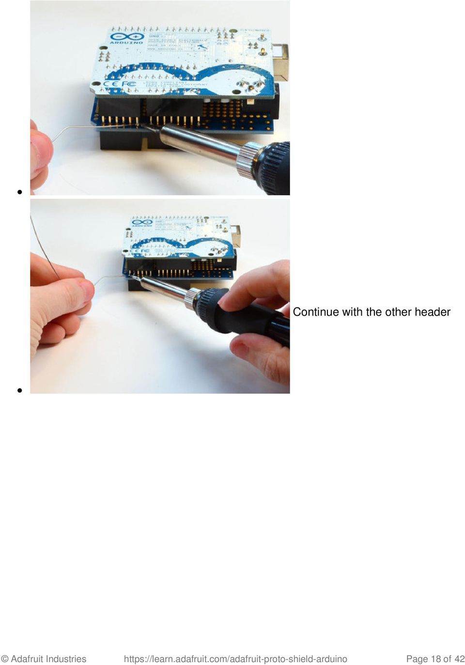
17 Now from above, solder the two end pins a stacky header to the PCB. You don't have to do a great job soldering, just make sure it's tacked together. Adafruit Industries Page 17 of 42

18 Continue with the other header Adafruit Industries Page 18 of 42
19 Flip around and do the other two headers Carefully remove the shield from Adafruit Industries Page 19 of 42

20 the Arduino and insert into your vise with the ends of the stacking header pointing up Now that you have aligned the Adafruit Industries Page 20 of 42

21 stacky headers using an Arduino it's easy to finish the job Solder the remaining header pins, including the two end pins just to make sure they are super solidly soldered :) Adafruit Industries Page 21 of 42
22 When done, check your work, make sure each pin is soldered with a nice shiny solder connection Adafruit Industries Page 22 of 42
23 Installing plain headers If you want to install the plain header rather than stacking headers, follow this part: Grab a plain Arduino Adafruit Industries Page 23 of 42
24 Next its time to make the male headers from the long strip. use diagonal cutters or pliers to clip off 4 parts, one 6-pin, two 8-pin, and one 10-pin Adafruit Industries Page 24 of 42
25 Place the pieces of header into the Arduino so the long pins are in the side sockets and the short pins stick up Place the PCB on top of the Arduino so the short pins stick through the rows of pads on either side Adafruit Industries Page 25 of 42
26 Solder all of the pads! Adafruit Industries Page 26 of 42
27 Check your work! Make sure every point is nice and shiny Installing Extras The Proto Shield comes with some extras like 2 buttons, 2 capacitors and a red/green LED set. These aren't essential but you may want to have them installed! Here's how you go about doing it! Installing Capacitors There's two spots for 0.1uF Adafruit Industries Page 27 of 42
28 ceramic capacitors. These are nice little additions that help keep your 5V power-supply clean Place the two ceramic capacitors in the spots shown. They are symmetric so you don't have to worry about putting them in backwards. Bend the two little capacitor leads out so that you can flip over the PCB without the caps falling out Adafruit Industries Page 28 of 42
29 Solder each of the 4 leads Check your work! Adafruit Industries Page 29 of 42
30 Then clip the leads short using a pair of diagonal cutters Installing Buttons There's two optional buttons you can solder into your Proto Shield. One is connected to the Arduino reset pin so you can quickly reset your Arduino. One is not connected to any pin, you can solder a wire from it to any other Arduino pin Snap the two buttons into the top corner of the PCB. They will snap Adafruit Industries Page 30 of 42
31 into place and sit flat against the PCB. They are symmetric so you can insert them 'either way' Flip over the board and solder the 4 pads of each button Adafruit Industries Page 31 of 42
32 Check your work to make sure the solder points are nice and shiny...you're done! Installing LEDs Next it's time to place the two 3mm LEDs. LEDs are directional, Adafruit Industries Page 32 of 42
33 and if you put them in backwards they wont work. LEDs have a positive lead and a negative lead. The positive lead is longer. On the Proto Shield PCB, you'll see a circle indicating where the LED goes, and a small + sign. That's the indicator for which pad gets the longer leg of the LED Next to the red LED you can bend one of the 1K ohm resistors over and insert it in the O- shaped silkscreen pads to the left Resistors do not have a direction, so they can be installed either way. Adafruit Industries Page 33 of 42
34 Next insert the small green LED between the two buttons. Like the red LED, check for the tiny + symbol on the PCB, aand place the longer leg of the LED into this pad. Then insert the other 1K resistor into the 0- marked spot right next to it On the Proto Shield PCB, you'll see a circle indicating where the LED goes, and a small + sign. That's the indicator for which pad gets the longer leg of the LED Adafruit Industries Page 34 of 42
35 Bend out the leads of the LEDs and resistors so they sit flat againt the PCB Flip over the PCB in your vise Solder in all the legs of the LEDs and resistors. Adafruit Industries Page 35 of 42
36 When done, check your work! Clip all the leads down so that the long wires are no longer than the solder points Adafruit Industries Page 36 of 42
37 If you want to use the red and green LEDs or the general purpose button, simply solder solid-gauge wire (~22awg is good) into the large solder holes near the device. Then you can plug the other end of the wire like a jumper into any of the female headers. The two LEDs are tied to ground through 1K or 1.5K resistors. The button simply connects the jumper to ground when pressed (use an internal or external pull-up). Check the schematic on the download page for specific details. SPI/ICSP Connector Adafruit Industries Page 37 of 42
38 If you need to stack with a board that uses hardware SPI, or maybe you want to reprogram your Arduino with an AVR programmer, you'll want access to the 2x3 pin SPI/ICSP connector. Grab the 6-pin stacking ICSP header and plug it into the header on your Arduino Plug the shield on top so that the 6 pins go through the matching holes in the PCB Adafruit Industries Page 38 of 42
39 Solder all 6 pads You're done! Adafruit Industries Page 39 of 42
40 5-Pin power rail connections If you're using the proto shield with a tiny breadboard you may want to solder in the two 5- pin headers to the 5V and GND rails near the end of the Proto Shield, its pretty easy! Place the two non-stacking 5-pin headers into the matching slots on the right hand side of the PCB. Use tape to keep them in place Flip over the board. Use more tape if you need to keep the headers from sliding out Adafruit Industries Page 40 of 42
41 Solder all the pads! Check your work, make sure all the pins are solidly attached Adafruit Industries Page 41 of 42
42 Adafruit Industries Last Updated: :06:29 PM UTC Page 42 of 42
43 Download Files EagleCAD PCB Files on GitHub ( Fritzing object in Adafruit Fritzing library ( (schematic view not functional, use for diagramming only!) Schematic Fabrication Print
44
DS1307 Real Time Clock Breakout Board Kit
 DS1307 Real Time Clock Breakout Board Kit Created by Tyler Cooper Last updated on 2015-10-15 11:00:14 AM EDT Guide Contents Guide Contents Overview What is an RTC? Parts List Assembly Arduino Library Wiring
Assembly and User Guide
 1 Amp Adjustable Electronic Load 30V Max, 1 Amp, 20 Watts Powered by: 9V Battery Assembly and User Guide Pico Load is a convenient constant current load for testing batteries and power supplies. The digital
Adafruit MCP9808 Precision I2C Temperature Sensor Guide
 Adafruit MCP9808 Precision I2C Temperature Sensor Guide Created by lady ada Last updated on 2014-04-22 03:01:18 PM EDT Guide Contents Guide Contents Overview Pinouts Power Pins I2C Data Pins Optional Pins
Martin County Amateur Radio Association. Nightfire Kits 1 LED Torch Kit 270016. Contents. Description
 Nightfire Kits 1 LED Torch Kit 270016 1 Contents Nightfire Kits LED Torch Kit 270016... 1 Description... 1 Safety and Assembly of the kit... 6 Required and Useful Tools... 7 Assembly... 8 Checkout and
RS232/DB9 An RS232 to TTL Level Converter
 RS232/DB9 An RS232 to TTL Level Converter The RS232/DB9 is designed to convert TTL level signals into RS232 level signals. This cable allows you to connect a TTL level device, such as the serial port on
BUILDING INSTRUCTIONS
 etap2hw 38 mm I2C to LCD Interface BUILDING INSTRUCTIONS October 2013 P. Verbruggen Rev 1.01 15-Oct-13 Page 1 Table of Contents Chapter 1 General Information 1.1 ESD Precautions 1.2 Further Supplies 1.3
Adafruit SHT31-D Temperature & Humidity Sensor Breakout
 Adafruit SHT31-D Temperature & Humidity Sensor Breakout Created by lady ada Last updated on 2016-06-23 10:13:40 PM EDT Guide Contents Guide Contents Overview Pinouts Power Pins: I2C Logic pins: Other Pins:
TEECES DOME LIGHTING SYSTEMS
 This lighting system was designed by John V (Teeces) to be a simple, customizable, expandable and affordable solution for dome lighting. An Arduino micro-controller is used to tell LED driver chips which
DIY Pocket LED Gamer - Tiny Tetris!
 DIY Pocket LED Gamer - Tiny Tetris! Created by Jianan Li Last updated on 2014-12-11 11:00:38 AM EST Guide Contents Guide Contents Overview Menu Brightness Adjust Tetris Snake Paint Parts & Tools Parts
Joule Thief 3.0 Kit. June 2012, Rev 1 1 http://www.easternvoltageresearch.com Joule Thief 3.0
 Kit Instruction Manual Eastern Voltage Research, LLC June 2012, Rev 1 1 http://www.easternvoltageresearch.com HIGH BRIGHTNESS LED THIS KIT USES A 1W CREE, HIGH BRIGHTNESS LED. DO NOT STARE AT THIS (OR
Pololu DRV8835 Dual Motor Driver Shield for Arduino
 Pololu DRV8835 Dual Motor Driver Shield for Arduino Pololu DRV8835 Dual Motor Driver Shield for Arduino, bottom view with dimensions. Overview This motor driver shield and its corresponding Arduino library
WHO ANSWERED FIRST? FIND OUT WITH THIS QUIZ BUZZER KIT
 WHO ANSWERED FIRST? FIND OUT WITH THIS QUIZ BUZZER KIT BUILD INSTRUCTIONS Before you put any components in the board or pick up the soldering iron, just take a look at the Printed Circuit Board (PCB).
ECEN 1400, Introduction to Analog and Digital Electronics
 ECEN 1400, Introduction to Analog and Digital Electronics Lab 4: Power supply 1 INTRODUCTION This lab will span two lab periods. In this lab, you will create the power supply that transforms the AC wall
Total solder points: 167 Difficulty level: beginner 1 2 3 4 5 advanced DMX CONTROLLED RELAY K8072 ILLUSTRATED ASSEMBLY MANUAL
 Total solder points: 167 Difficulty level: beginner 1 2 3 4 5 advanced DMX CONTROLLED RELAY K8072 Control a relay by means of the wellknown DMX512 protocol. ILLUSTRATED ASSEMBLY MANUAL H8072IP-1 Features
step 1 Unpack the lunchbox And check whether you have got all the components~ If you have questions please contact us at: info@unitunlikely.
 step 1 Unpack the lunchbox And check whether you have got all the components~ If you have questions please contact us at: [email protected] This part is called the PCB (printed circuit board). All
Electronics and Soldering Notes
 Electronics and Soldering Notes The Tools You ll Need While there are literally one hundred tools for soldering, testing, and fixing electronic circuits, you only need a few to make robot. These tools
K8025 VIDEO PATTERN GENERATOR. Check the picture quality of your monitor or TV, ideal for adjustment or troubleshooting.
 K8025 ILLUSTRATED ASSEMBLY MANUAL H8025IP 1 VIDEO PATTERN GENERATOR Check the picture quality of your monitor or TV, ideal for adjustment or troubleshooting. Forum Participate our Velleman Projects Forum
AXE114S BINARY CLOCK. revolution Revolution Education Ltd. Email: [email protected] Web: www.rev-ed.co.uk Version 1.1 12/09/08 AXE114.PMD.
 AXE114S BINARY CLOCK Features: The PICAXE binary clock kit tells the time by lighting up blue LEDs in a binary pattern. This is a useful tool for teaching students binary code or simply just confusing/
7-SEGMENT DIGITAL CLOCK
 57mm 7-SEGMENT DIGITAL CLOCK Large 57mm clock & temperature display with extra unique feature Total solder points: 263 Difficulty level: beginner 1 2 3 4 5 advanced K8089 ILLUSTRATED ASSEMBLY MANUAL H8089IP-1
ARDUINO SEVERINO SERIAL SINGLE SIDED VERSION 3 S3v3 (REVISION 2) USER MANUAL
 USER MANUAL") ARDUINO SEVERINO SERIAL SINGLE SIDED VERSION 3 S3v3 (REVISION 2) USER MANUAL X1: DE-9 serial connector Used to connect computer (or other devices) using RS-232 standard. Needs a serial cable, with at least
ARDUINO SEVERINO SERIAL SINGLE SIDED VERSION 3 S3v3 (REVISION 2) USER MANUAL X1: DE-9 serial connector Used to connect computer (or other devices) using RS-232 standard. Needs a serial cable, with at least
400W MONO/STEREO AMPLIFIER
 400W MONO/STEREO AMPLIFIER Universal, robust and compact are the words to describe this amplifier. Total solder points: 264 Difficulty level: beginner 1 2 3 4 5 advanced K4005B ILLUSTRATED ASSEMBLY MANUAL
The $25 Son of a cheap timer This is not suitable for a beginner. You must have soldering skills in order to build this kit.
 The $25 Son of a cheap timer This is not suitable for a beginner. You must have soldering skills in order to build this kit. Micro Wizard has been manufacturing Pinewood Derby timers for over 10 years.
BMD16N-SD. version 1.2
 BMD16NSD version 1.2 Feedback decoder with 16 contacts with integrated current detection for the S88bus Compatible with a.o. Märklin Digital, Uhlenbrock Intellibox, Fleischmann TwinCenter and LDT HSI88
Elecraft K3 KPA3 Power Connector Replacement Revision A Review, April 16, 2012 Copyright 2012, Elecraft, Inc. All Rights Reserved
 Introduction Elecraft K3 KPA3 Power Connector Replacement Revision A Review, April 16, 2012 Copyright 2012, Elecraft, Inc. All Rights Reserved The connectors furnishing high current to the KPA3 module
Cell Phone Charging Purse
 Cell Phone Charging Purse Created by Becky Stern Last updated on 2015-02-20 01:00:16 PM EST Guide Contents Guide Contents Overview Prepare USB and Power Supply Create a Charging Shelf Install Coil in Bag
DET Practical Electronics (Intermediate 1)
") DET Practical Electronics (Intermediate 1) 731 August 2000 HIGHER STILL DET Practical Electronics (Intermediate 1) Support Materials CONTENTS Section 1 Learning about Resistors Section 2 Learning about
DET Practical Electronics (Intermediate 1) 731 August 2000 HIGHER STILL DET Practical Electronics (Intermediate 1) Support Materials CONTENTS Section 1 Learning about Resistors Section 2 Learning about
GLOLAB Universal Telephone Hold
 GLOLAB Universal Telephone Hold 1 UNIVERSAL HOLD CIRCUIT If you have touch tone telephone service, you can now put a call on hold from any phone in the house, even from cordless phones and phones without
Adafruit BME280 Humidity + Barometric Pressure + Temperature Sensor Breakout
 Adafruit BME280 Humidity + Barometric Pressure + Temperature Sensor Breakout Created by lady ada Last updated on 2016-04-26 12:01:06 PM EDT Guide Contents Guide Contents Overview Pinouts Power Pins: SPI
Time needed: ~3h for lid replacement only. Add 1h for operation harness in lid and ~2h more for installing drive unit and cable harness in trunk.
 DIY for replacing trunk lid and/or retrofitting electrical operation of trunk lid. This document is meant to be a support and give advice on the procedure but I will take no responsibility for any damage
Support: http://www.evilmadscientist.com/forum/
 An open-source hardware+software project. For design files and additional documentation, please visit: http://www.evilmadscientist.com/go/diavolino Support: http://www.evilmadscientist.com/forum/ Distributed
Total solder points: 205 Difficulty level: beginner 1 2 3 4 5 advanced UNIVERSAL BATTERY CHARGER / DISCHARGER K7300 ILLUSTRATED ASSEMBLY MANUAL
 Total solder points: 205 Difficulty level: beginner 1 2 3 4 5 advanced UNIVERSAL BATTERY CHARGER / DISCHARGER K7300 Automatic (dis)charging of both NiCd and NiMH batteries. ILLUSTRATED ASSEMBLY MANUAL
7" Portable HDMI Monitor
 7" Portable HDMI Monitor Created by Ruiz Brothers Last updated on 2015-10-28 06:10:09 PM EDT Guide Contents Guide Contents Overview DIY Monitor Connect to a Raspberry pi Use as a second monitor Camera
Modifying the Yaesu FT-847 External 22.625 MHz Reference Input
 Modifying the Yaesu FT-847 External 22.625 MHz Reference Input David Smith VK3HZ Introduction This document describes the modification of an FT-847 to allow an external 22.625 MHz Reference oscillator
2.2" TFT Display. Created by Ladyada. Last updated on 2014-03-31 12:15:09 PM EDT
 2.2" TFT Display Created by Ladyada Last updated on 2014-03-31 12:15:09 PM EDT Guide Contents Guide Contents Overview Connecting the Display Test the Display Graphics Library Bitmaps Alternative Wiring
K128. USB PICmicro Programmer. DIY Electronics (HK) Ltd PO Box 88458, Sham Shui Po, Hong Kong. http://www.kitsrus.com mailto: peter@kitsrus.
 Ltd PO Box 88458, Sham Shui Po, Hong Kong. http://www.kitsrus.com mailto: peter@kitsrus.") K128 USB PICmicro Programmer DIY Electronics (HK) Ltd PO Box 88458, Sham Shui Po, Hong Kong http://www.kitsrus.com mailto: [email protected] Last Modified March 31 2003 Board Construction The board is
K128 USB PICmicro Programmer DIY Electronics (HK) Ltd PO Box 88458, Sham Shui Po, Hong Kong http://www.kitsrus.com mailto: [email protected] Last Modified March 31 2003 Board Construction The board is
1.8" TFT Display Breakout and Shield
 1.8" TFT Display Breakout and Shield Created by lady ada Last updated on 2015-04-09 03:48:28 PM EDT Guide Contents Guide Contents Overview Breakout Pinouts Breakout Assembly Prepare the header strip: Add
Building A Computer: A Beginners Guide
 Building A Computer: A Beginners Guide Mr. Marty Brandl The following was written to help an individual setup a Pentium 133 system using an ASUS P/I- P55T2P4 motherboard. The tutorial includes the installation
Basic soldering is a skill that's easy to learn and not too hard to master. It just takes practice.
 From www.mediacollege.com How to Solder Basic soldering is a skill that's easy to learn and not too hard to master. It just takes practice. There is a huge range of soldered joints out there, from tiny
PolyBot Board. User's Guide V1.11 9/20/08
 PolyBot Board User's Guide V1.11 9/20/08 PolyBot Board v1.1 16 pin LCD connector 4-pin SPI port (can be used as digital I/O) 10 Analog inputs +5V GND GND JP_PWR 3-pin logic power jumper (short top 2 pins
K6002 TEMPERATURE CONTROLLER. Specifications
 Total solder points: 169 + 99 + 67 Difficulty level: beginner 1 2 3 4 5 advanced TEMPERATURE CONTROLLER K6002 Unlike a normal thermostat, this kit has two outputs, one for "high" alarm and one for "low"
Bill Conkling July 2012
 Bill Conkling July 2012 Introduction: For any ham, there are moments that are priceless, like snagging that elusive rare DX station on a deserted island that hasn t been activated in 52 years. And certainly,
How to connect to a Class II router using a mobile-phone data cable specifically for Solwise & Safecom routers
 USB to router s serial port How to connect to a Class II router using a mobile-phone data cable specifically for Solwise & Safecom routers by Neo at RouterTech.Org Introduction Routers based on the AR7RD/AR7WRD
Total solder points: 129 Difficulty level: beginner 1 2 3 4 5 advanced LIQUID LEVEL CONTROLLER K2639 ILLUSTRATED ASSEMBLY MANUAL H2639IP-1
 Total solder points: 129 Difficulty level: beginner 1 2 3 4 5 advanced LIQUID LEVEL CONTROLLER K2639 Forgotten to turn off the tap, leaking washing machines,... Prevention is better than cure. So use this
15 Channel IR transmitter. Total solder points: 53 Difficulty level: beginner 1 2 3 4 5 advanced K8049 ILLUSTRATED ASSEMBLY MANUAL
 15 Channel IR transmitter Compatible with most Velleman IR receiver kits, 4 adresses allow the use of multiple receivers in one room. Total solder points: 53 Difficulty level: beginner 1 2 3 4 5 advanced
!Operation:!1. Connect an external power source to J1 (+ and - IN terminals). The
. The") The CB500 Electronic Circuit Breaker is an resettable circuit breaker (fuse) that disconnects power when the trip setting is exceeded. There are 4 trip settings that can easily be changed and set during
The CB500 Electronic Circuit Breaker is an resettable circuit breaker (fuse) that disconnects power when the trip setting is exceeded. There are 4 trip settings that can easily be changed and set during
Tutorials Drawing a 555 timer circuit
 Step 1 of 10: Introduction This tutorial shows you how to make an electronic circuit using Livewire and PCB Wizard 3. You should follow this tutorial to learn the basic skills you will need to use Livewire
Adafruit Music Maker Shield
 Adafruit Music Maker Shield Created by lady ada Last updated on 2015-10-09 02:10:09 PM EDT Guide Contents Guide Contents Overview Pinouts Main Control Breakouts SPI Jumpers GPIO Breakouts MicroSD Card
Your Multimeter. The Arduino Uno 10/1/2012. Using Your Arduino, Breadboard and Multimeter. EAS 199A Fall 2012. Work in teams of two!
 Using Your Arduino, Breadboard and Multimeter Work in teams of two! EAS 199A Fall 2012 pincer clips good for working with breadboard wiring (push these onto probes) Your Multimeter probes leads Turn knob
Document number RS-PRD-00130 Revision 05 Date 20/10/2009 Page 1/30
 Date 20/10/2009 Page 1/30 1. Purpose This document describes the field replacement of the footscan plate cable for these models: 2m hi-end plate SN 11/5/xxx 2m pro plate SN 7/5/xxx 0.5m 2003 hi-end plate
1.5" & 2.1" Monochrome 128x64 OLED Display Module
 1.5" & 2.1" Monochrome 128x64 OLED Display Module Created by lady ada Last updated on 2016-02-16 11:27:52 AM EST Guide Contents Guide Contents Overview Pinouts Power Pins Signal Pins Remaining Pins Assembly
DUAL ELECTRONIC DICE K3400
 DUAL ELECTRONIC DICE K3400 Cheating is no longer possible! ILLUSTRATED ASSEMBLY MANUAL H3400IP-1 VELLEMAN NV Legen Heirweg 33 9890 Gavere Belgium Europe www.velleman.be www.velleman-kit.com Features &
POCKET AUDIO GENERATOR K8065
 POCKET AUDIO GENERATOR K8065 Great little gadget for service repair, testing, education, etc... ILLUSTRATED ASSEMBLY MANUAL H8065IP-1 VELLEMAN NV Legen Heirweg 33 9890 Gavere Belgium Europe www.velleman.be
QSI Auto-Focus Mounting Bracket
 QSI Auto-Focus Mounting Bracket The camera mounting bracket makes extensive use of sliding dovetails. The dovetail joint gets immense strength from a trapezoidal pin trapped in a slot. The internal flats
Arduino ADK Back. For information on using the board with the Android OS, see Google's ADK documentation.
 Arduino ADK Arduino ADK R3 Front Arduino ADK R3 Back Arduino ADK Front Arduino ADK Back Overview The Arduino ADK is a microcontroller board based on the ATmega2560 (datasheet). It has a USB host interface
 P105 SINGLE STICK REVERSER PICTURE 1: PCB with headers PICTURE 3: Resistors added PICTURE 5: Add tactile switch (button) PICTURE 7: Fit lead and PIC chip. NOTE! ANTI-STATIC PRECAUTIONS REQUIRED PICTURE
GUITAR PREAMPLIFIER WITH HEADPHONE OUTPUT K4102
 H4102IP-1 GUITAR PREAMPLIFIER WITH HEADPHONE OUTPUT K4102 Practice the guitar without disturbing others. Features & Specifications Features: An electric guitar cannot be connected to just any amplifier
PN532 NFC RFID Module User Guide
 PN532 NFC RFID Module User Guide Version 3 Introduction NFC is a popular technology in recent years. We often heard this word while smart phone company such as Samsung or HTC introduces their latest high-end
Arduino Lesson 14. Servo Motors
 Arduino Lesson 14. Servo Motors Created by Simon Monk Last updated on 2013-06-11 08:16:06 PM EDT Guide Contents Guide Contents Overview Parts Part Qty The Breadboard Layout for 'Sweep' If the Servo Misbehaves
Character LCDs. Created by Ladyada. Last updated on 2013-07-26 02:45:29 PM EDT
 Character LCDs Created by Ladyada Last updated on 2013-07-26 02:45:29 PM EDT Guide Contents Guide Contents Overview Character vs. Graphical LCDs LCD Varieties Wiring a Character LCD Installing the Header
How to Make a Pogo Pin Test Jig. Created by Tyler Cooper
 How to Make a Pogo Pin Test Jig Created by Tyler Cooper Guide Contents Guide Contents Overview Preparation Arduino Shield Jigs The Code Testing Advanced Pogo Jigs Support Forums 2 3 4 6 9 11 12 13 Adafruit
Arduino Lesson 0. Getting Started
 Arduino Lesson 0. Getting Started Created by Simon Monk Last updated on 204-05-22 2:5:0 PM EDT Guide Contents Guide Contents Overview Parts Part Qty Breadboard Installing Arduino (Windows) Installing Arduino
GT3B Hack Kit Install Instructions Written By Austin Hutchison
 GT3B Hack Kit Install Instructions Written By Austin Hutchison Step 1: Remove 4 screws located on top of the radio. 1 Step 2: There are small plastic latches that also hold the top in place. The easiest
Arduino Lesson 13. DC Motors. Created by Simon Monk
 Arduino Lesson 13. DC Motors Created by Simon Monk Guide Contents Guide Contents Overview Parts Part Qty Breadboard Layout Arduino Code Transistors Other Things to Do 2 3 4 4 4 6 7 9 11 Adafruit Industries
Juice Box Stages 1&2 135&335 Installation Guide 5/10/08
 Tools Required: 8mm socket or nut driver Small flat head screwdriver Electrical tape, masking tape, or shrink tube Pep talk: Although the install looks daunting at first, once you get the learning curve
2.3" Monochrome 128x32 OLED Display Module
 2.3" Monochrome 128x32 OLED Display Module Created by lady ada Last updated on 2016-03-27 06:56:07 AM EDT Guide Contents Guide Contents Overview Pinouts Power Pins Signal Pins Remaining Pins Assembly Changing
DATASHEET. ADAM Arduino Display Adaptor Module. Arduino Compatible Shield P/N: 4Display-Shield-FT843 For the 4D Systems 4DLCD-FT843 Display
 DATASHEET ADAM Arduino Display Adaptor Module Arduino Compatible Shield P/N: 4Display-Shield-FT843 For the 4D Systems 4DLCD-FT843 Display Document Date: 8 th January 2014 Document Revision: 1.0 Uncontrolled
EXPRESS PCB TUTORIAL Author: Lee Morey Revised: JE Feb 2015
 EXPRESS PCB TUTORIAL Author: Lee Morey Revised: JE Feb 2015 Getting Started There are several resources for learning how to layout schematics and PCBs. And there are several popular commercial packages.
Knight Audio Technologies Ltd. Deacy - Style Amplifier Kit Build Instructions
 Knight Audio Technologies Ltd Deacy - Style Amplifier Kit Build Instructions Introduction Firstly, thank you for purchasing this amplifier kit. We have designed this amplifier based on the Mullard 1960
XBee USB Adapter Board (#32400)
") Web Site: www.parallax.com Forums: forums.parallax.com Sales: [email protected] Technical: [email protected] Office: (916) 624-8333 Fax: (916) 624-8003 Sales: (888) 512-1024 Tech Support: (888) 997-8267
Web Site: www.parallax.com Forums: forums.parallax.com Sales: [email protected] Technical: [email protected] Office: (916) 624-8333 Fax: (916) 624-8003 Sales: (888) 512-1024 Tech Support: (888) 997-8267
SMD Soldering Guide by Infidigm
 SMD Soldering Guide by Infidigm Purpose The purpose of this guide is to introduce SMD (Surface Mount Device) hand soldering. The guide is organized into different methods. Each method is used specifically
AUTOMATIC CALL RECORDER JAMECO PART NO. 2163735
 AUTOMATIC CALL RECORDER JAMECO PART NO. 2163735 Experience Level: Intermediate Time Required: 1-2 Hours This project automatically records phone calls. The program, along with the adapter records each
TEACHING RESOURCES SCHEMES OF WORK DEVELOPING A SPECIFICATION COMPONENT FACTSHEETS HOW TO SOLDER GUIDE GET IN TUNE WITH THIS FM RADIO KIT. Version 2.
 TEACHING RESOURCES SCHEMES OF WORK DEVELOPING A SPECIFICATION COMPONENT FACTSHEETS HOW TO SOLDER GUIDE GET IN TUNE WITH THIS FM RADIO KIT Version 2.0 Index of Sheets TEACHING RESOURCES Index of Sheets
Model 201 Wiegand Touchpad Reader Installation Guide
 Model 201 Wiegand Touchpad Reader Installation Guide P/N 460353001C 15AUG11 2011 UTC Fire & Security. All rights reserved. This document may not be copied in whole or in part or otherwise reproduced without
ENGS 32 Winter, 2003. Prototyping Methods
 There s more on this in Scherz, Practical Electronics for Inventors. Solderless Breadboard or Plugboard This is what we ve been using in lab. Very fast to build and make changes. Works well with DIP ICs
WICE-SPI Hardware Operation Manual
 Contents 1.Hardware Instruction...1 2. Pin Definition Of WICE-SPI Connector...2 3. Peripheral Circuit Arrangements...3 4. On-Board Programming...4 5. Off-Line Programming...8 1.Hardware Instruction 1.WICE-SPI
SUPER SNOOPER BIG EAR
 AA-1D Super Snooper Big Ear SPECIFICATIONS Operates on 5 to 9v DC Will drive a small speaker Provides up to 1 watt of audio power Distortion > 0.2% Voltage Gain up to 46 db Size: 1 x 1.95 Rainbowkits.com
INSTALLATION INSTRUCTIONS
 INSTALLATION INSTRUCTIONS Accessory Application Publications No. ACCORD All 30209 2-AND 4-DOOR SYSTEM (VP, LX, SE) Issue Date AUG 2005 PARTS LIST Security System Attachment: P/N 08E55-SDA-100A Unit panel
TSL2561 Luminosity Sensor
 TSL2561 Luminosity Sensor Created by lady ada Last updated on 2015-06-12 12:10:28 PM EDT Guide Contents Guide Contents Overview Wiring the TSL2561 Sensor Using the TSL2561 Sensor Downloads Buy a TSL2561
Analog control unit for mobile robots
 Analog control unit for mobile robots Soldering kit for experimentation For Fischertechnik robots and others Most diverse functions Requires no programming Patented sensor technology Summary We are pleased
ROTOPOD PERISCOPE LIGHTING KIT (for MCWHLR & Daniel D/Xeno Periscopes)
") ROTOPOD PERISCOPE LIGHTING KIT (for MCWHLR & Daniel D/Xeno Periscopes) 14-APR-2012_rev 1.2 I designed the Periscope Lighting Kit to be as flexible as possible. Every LED is individually controllable. I
ROTOPOD PERISCOPE LIGHTING KIT (for MCWHLR & Daniel D/Xeno Periscopes) 14-APR-2012_rev 1.2 I designed the Periscope Lighting Kit to be as flexible as possible. Every LED is individually controllable. I
SYMMETRIC 1A POWER SUPPLY K8042
 SYMMETRIC 1A POWER SUPPLY K8042 Low cost universal symmetric power supply ILLUSTRATED ASSEMBLY MANUAL H8042IP-1 Features & Specifications Features low cost universal symmetric power supply just add a suitable
Arduino Lesson 1. Blink
 Arduino Lesson 1. Blink Created by Simon Monk Last updated on 2015-01-15 09:45:38 PM EST Guide Contents Guide Contents Overview Parts Part Qty The 'L' LED Loading the 'Blink' Example Saving a Copy of 'Blink'
Arduino Due Back. Warning: Unlike other Arduino boards, the Arduino Due board runs at 3.3V. The maximum. Overview
 R Arduino Due Arduino Due Front Arduino Due Back Overview The Arduino Due is a microcontroller board based on the Atmel SAM3X8E ARM Cortex-M3 CPU (datasheet). It is the first Arduino board based on a 32-bit
A REST API for Arduino & the CC3000 WiFi Chip
 A REST API for Arduino & the CC3000 WiFi Chip Created by Marc-Olivier Schwartz Last updated on 2014-04-22 03:01:12 PM EDT Guide Contents Guide Contents Overview Hardware configuration Installing the library
Total solder points: 57 Difficulty level: beginner 1 2 3 4 5 advanced 3 TO 30VDC / 3A POWER SUPPLY K7203 ILLUSTRATED ASSEMBLY MANUAL H7203IP-1
 Total solder points: 57 Difficulty level: beginner 1 2 3 4 5 advanced 3 TO 30VDC / 3A POWER SUPPLY K7203 A power supply for all our kits, based on a stabilised DC voltage of 30V. ILLUSTRATED ASSEMBLY MANUAL
LED Wiring and Connections
 LED Wiring and Connections A Handbook of How-to Manuals 2009 usledsupply. All Rights Reserved. Index These step by step how to manuals will give you the foundation necessary to use your new LED lights.
K8068 BUS DIMMER FOR HOME MODULAR LIGHT SYSTEM ILLUSTRATED ASSEMBLY MANUAL H8068IP-1
 Total solder points: 74 Difficulty level: beginner 1 2 3 4 5 advanced BUS DIMMER FOR HOME MODULAR LIGHT SYSTEM K8068 PLUG - IN module for use with home modular lights system K8006. For electronic transformers!
Tiny Arduino Music Visualizer
 Tiny Arduino Music Visualizer Created by Phillip Burgess Last updated on 2014-04-17 09:30:35 PM EDT Guide Contents Guide Contents Overview Wiring Code Troubleshooting Principle of Operation Ideas 2 3 4
Total solder points: 147 Difficulty level: beginner 1 2 3 4 5 advanced VIDEO SIGNAL CLEANER K8036 ILLUSTRATED ASSEMBLY MANUAL
 Total solder points: 147 Difficulty level: beginner 1 2 3 4 5 advanced VIDEO SIGNAL CLEANER K8036 Digitally cleans the video signal of unwanted distortions and improves the picture quality. ILLUSTRATED
DIGITAL PC SCOPE. Total solder points: 625 Difficulty level: beginner 1 2 3 4 5 advanced K8031 ILLUSTRATED ASSEMBLY MANUAL
 DIGITAL PC SCOPE Digital storage oscilloscoop, using a computer and its monitor to display waveforms. All standard oscilloscope functions are available in the Windows program supplied. Total solder points:
Optical Sensor Interface for AFX Digital LED Timer/Counter by George Warner, Jan. 2003 [email protected]
 Optical Sensor Interface for AFX Digital LED Timer/Counter by George Warner, Jan. 200 [email protected] Abstract This paper presents a design for an optical sensor interface to an AFX Digital LED Timer/Counter.
Total solder points: 115 Difficulty level: beginner 1 2 3 4 5 advanced 4 CHANNEL RUNNING LIGHT K8032 ILLUSTRATED ASSEMBLY MANUAL
 Total solder points: 115 Difficulty level: beginner 1 2 3 4 5 advanced 4 CHANNEL RUNNING LIGHT K8032 Ideal for creating disco light effects, light speed adjustable. Suited for inductive loads. ILLUSTRATED
Odyssey of the Mind Technology Fair. Simple Electronics
 Simple Electronics 1. Terms volts, amps, ohms, watts, positive, negative, AC, DC 2. Matching voltages a. Series vs. parallel 3. Battery capacity 4. Simple electronic circuit light bulb 5. Chose the right
VOLUME AND TONE CONTROL - PREAMPLIFIER K8084
 H8084IP-1 VOLUME AND TONE CONTROL - PREAMPLIFIER K8084 When using one of our amplifiers (big or small), you always need a volume control and preferably also a tone control Features & specifications When
DIY Bluetooth Gamepad
 DIY Bluetooth Gamepad Created by Ruiz Brothers Last updated on 2015-03-11 03:15:13 PM EDT Guide Contents Guide Contents Overview Prerequisite Guides Expectations Parts Tools & Supplies Circuit Diagram
Name: Bicycle Cellphone Charger Circuit Assembly Manual Device: Nokia/Blackberry List of Components:
 Name: Bicycle Cellphone Charger Circuit Assembly Manual Device: Nokia/Blackberry List of Components: Serial numbername Quantity Component number 1 5 V Regulator 1 U2 2 10 MicroFarad Capacitor 1 C1 3 22
Objectives: Part 1: Build a simple power supply. CS99S Laboratory 1
 CS99S Laboratory 1 Objectives: 1. Become familiar with the breadboard 2. Build a logic power supply 3. Use switches to make 1s and 0s 4. Use LEDs to observe 1s and 0s 5. Make a simple oscillator 6. Use
DIY Wearable Pi with Near-Eye Video Glasses
 DIY Wearable Pi with Near-Eye Video Glasses Created by Ruiz Brothers Last updated on 2015-02-20 09:31:15 AM EST Guide Contents Guide Contents Overview 3D Printing Disassembly Assembly Video Configurations