Arduino Lesson 4. Eight LEDs and a Shift Register
|
|
|
- Imogen Bennett
- 7 years ago
- Views:
Transcription
1 Arduino Lesson 4. Eight LEDs and a Shift Register Created by Simon Monk Last updated on :30:10 AM EDT

2 Guide Contents Guide Contents Overview Parts Part Qty Breadboard Layout The 74HC595 Shift Register Arduino Code Brightness Control Other Things to Do Adafruit Industries Page 2 of 17

3 Overview In this lesson, you will learn how to use eight large red LEDs with an Arduino without needing to give up 8 output pins! Although you could wire up eight LEDs each with a resistor to an Arduino pin (like we did for an RGB LED in Lesson 2) you would rapidly start to run out of pins on your Arduino. If you don't have a lot of stuff connected to your 'duino it's OK to do so - but often times we want buttons, sensors, servos, etc and before you know it you've got no pins left. So, instead of doing that, you are going to use a chip called the 74HC595 Serial to Parallel Co nverter. This chip has eight outputs (perfect) and three inputs that you use to feed data into it a bit at a time. This chip makes it a little slower to drive the LEDs (you can only change the LEDs about 500,000 times a second instead of 8,000,000 a second) but it's still really really fast, way faster than humans can detect, so it's worth it! Adafruit Industries Page 3 of 17

4 Parts To build the project described in this lesson, you will need the following parts. Part Qty 5mm Red LED Ω Resistors (red, purple, brown stripes) 8 Adafruit Industries Page 4 of 17
 8 Adafruit Industries https://learn.adafruit.")
5 74HC595 Shift Register 1 Half-size Breadboard 1 Adafruit Industries Page 5 of 17

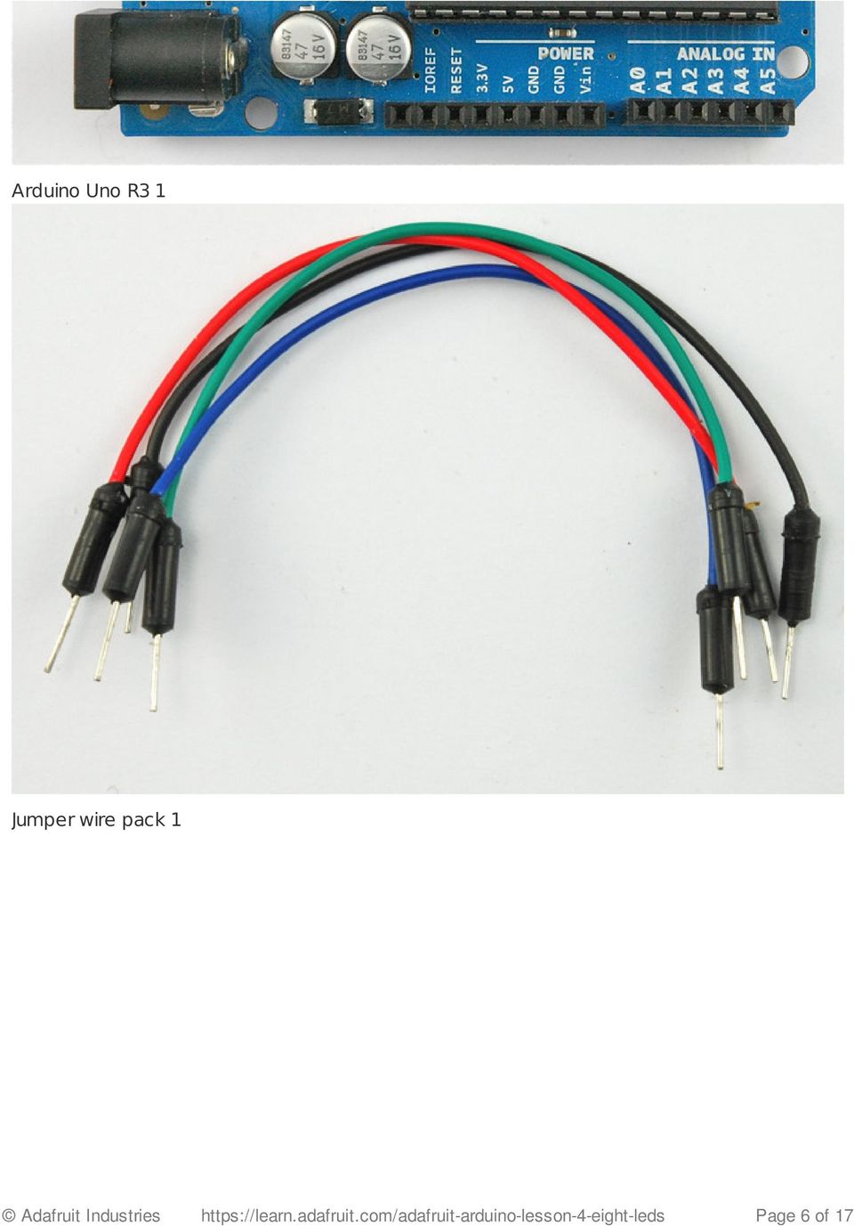
6 Arduino Uno R3 1 Jumper wire pack 1 Adafruit Industries Page 6 of 17
7 Breadboard Layout As we have eight LEDs and eight resistors to connect up, there are actually quite a few connections to be made. It is probably easiest to put the 74HC595 chip in first, as pretty much everything else connects to it. Put it so that the little U-shaped notch is towards the top of the breadboard. Pin 1 of the chip is to the left of this notch. Digital 4 from the arduino goes to pin #14 of the shift register Digital 5 from the arduino goes to pin #12 of the shift register Digital 6 from the arduino goes to pin #11 of the shift register All but one of the outputs from the '595 are on the left hand side of the chip, hence, for ease Adafruit Industries Page 7 of 17

8 of connection, that is where the LEDs are too. After the chip, put the resistors in place. You need to be careful that none of the leads of the resistors are touching each other. You should check this again, before you connect the power to your Arduino. If you find it difficult to arrange the resistors without their leads touching, then it helps to shorten the leads so that they are lying closer to the surface of the breadboard.next, place the LEDs on the breadboard. The longer positive LED leads must all be towards the chip, whichever side of the breadboard they are on. It now just remains to attach the jumper leads as shown above. Do not forget the one that goes from pin 8 of the IC to the GND column of the breadboard. Load up the sketch listed a bit later and try it out. Each LED should light in turn until all the LEDs are on, and then they all go off and the cycle repeats. Adafruit Industries Page 8 of 17

9 The 74HC595 Shift Register Before I go through the code, let's have a quick look at what the chip is doing, so that we can understand what the code has to do. The chip is of a type called a shift register. Adafruit Industries Page 9 of 17

10 The shift register holds what can be thought of as eight memory locations, each of which can be a 1 or a 0. Adafruit Industries Page 10 of 17

11 To set each of these values on or off, we feed in the data using the 'Data' and 'Clock' pins of the chip. The clock pin needs to receive eight pulses, at the time of each pulse, if the data pin is high, then a 1 gets pushed into the shift register, otherwise a 0. When all eight pulses have been received, then enabling the 'Latch' pin copies those eight values to the latch register. This is necessary, otherwise the wrong LEDs would flicker as the data was being loaded into the shift register. The chip also has an OE (output enable) pin, this is used to enable or disable the outputs all at once. You could attach this to a PWM capable Arduino pin and use 'analogwrite' to control the brightness of the LEDs. This pin is active low, so we tie it to GND. Adafruit Industries Page 11 of 17

12 Arduino Code Arduino includes a special function called 'shiftout' that is designed specifically for sending data to shift registers. Here is the full sketch, the discussion of how it works follows on from it. /* Adafruit Arduino - Lesson 4. 8 LEDs and a Shift Register */ int latchpin = 5; int clockpin = 6; int datapin = 4; byte leds = 0; void setup() pinmode(latchpin, OUTPUT); pinmode(datapin, OUTPUT); pinmode(clockpin, OUTPUT); void loop() leds = 0; updateshiftregister(); delay(500); for (int i = 0; i < 8; i++) bitset(leds, i); updateshiftregister(); delay(500); void updateshiftregister() digitalwrite(latchpin, LOW); shiftout(datapin, clockpin, LSBFIRST, leds); digitalwrite(latchpin, HIGH); The first thing we do is define the three pins we are going to use. These are the Arduino Adafruit Industries Page 12 of 17
 leds = 0; updateshiftregister(); delay(500); for (int i = 0; i < 8; i++) bitset(leds, i); updateshiftregister(); delay(500); void updateshiftregister() digitalwrite(latchpin, LOW);")
13 digital outputs that will be connected to the latch, clock and data pins of the 74HC595. int latchpin = 5; int clockpin = 6; int datapin = 4; Next, a variable called 'leds' is defined. This will be used to hold the pattern of which LEDs are currently turned on or off. Data of type 'byte' represents numbers using eight bits. Each bit can be either on or off, so this is perfect for keeping track of which of our eight LEDs are on or off. byte leds = 0; The 'setup' function just sets the three pins we are using to be digital outputs. void setup() pinmode(latchpin, OUTPUT); pinmode(datapin, OUTPUT); pinmode(clockpin, OUTPUT); The 'loop' function initially turns all the LEDs off, by giving the variable 'leds' the value 0. It then calls 'updateshiftregister' that will send the 'leds' pattern to the shift register so that all the LEDs turn off. We will deal with how 'updateshiftregister' works later. The loop function pauses for half a second and then begins to count from 0 to 7 using the 'for' loop and the variable 'i'. Each time, it uses the Arduino function 'bitset' to set the bit that controls that LED in the variable 'leds'. It then also calls 'updateshiftregister' so that the leds update to reflect what is in the variable 'leds'. There is then a half second delay before 'i' is incremented and the next LED is lit. void loop() leds = 0; updateshiftregister(); delay(500); for (int i = 0; i < 8; i++) bitset(leds, i); updateshiftregister(); Adafruit Industries Page 13 of 17

14 delay(500); The function 'updateshiftregister', first of all sets the latchpin to low, then calls the Arduino function 'shiftout' before putting the 'latchpin' high again. This takes four parameters, the first two are the pins to use for Data and Clock respectively. The third parameter specifies which end of the data you want to start at. We are going to start with the right most bit, which is referred to as the 'Least Significant Bit' (LSB). The last parameter is the actual data to be shifted into the shift register, which in this case is 'leds'. void updateshiftregister() digitalwrite(latchpin, LOW); shiftout(datapin, clockpin, LSBFIRST, leds); digitalwrite(latchpin, HIGH); If you wanted to turn one of the LEDs off rather than on, you would call a similar Arduino function (bitclear) on the 'leds' variable. This will set that bit of 'leds' to be 0 and you would then just need to follow it with a call to 'updateshiftregister' to update the actual LEDs. Adafruit Industries Page 14 of 17

15 Brightness Control One pin of the 74HC595 that I have not mentioned is a pin called 'Output Enable'. This is pin 13 and on the breadboard, it is permanently connected to Ground. This pin acts as a switch, that can enable or disable the outputs - the only thing to watch for is it is 'active low' (connect to ground to enable). So, if it is connected to 5V, all the outputs go off. Whereas if it is connected to Ground, those outputs that are supposed to be on are on and those that should be off are off. We can use this pin along with the 'analogwrite' function, that we used back in Lesson 3, to control the brightness of the LEDs using PWM (also see Lesson 3). To do this, all you need to do, is to change the connection to pin 13 of the 74HC595 so that instead of connecting it to Ground, you connect it to pin 3 of the Arduino. The sketch below, will once all the LEDs have been lit gradually fade them back to off. /* Adafruit Arduino - Lesson 4. 8 LEDs and a Shift Register - Brightness */ int latchpin = 5; int clockpin = 6; int datapin = 4; int outputenablepin = 3; byte leds = 0; void setup() pinmode(latchpin, OUTPUT); pinmode(datapin, OUTPUT); pinmode(clockpin, OUTPUT); pinmode(outputenablepin, OUTPUT); void loop() setbrightness(255); leds = 0; updateshiftregister(); delay(500); for (int i = 0; i < 8; i++) bitset(leds, i); Adafruit Industries Page 15 of 17
.")
16 updateshiftregister(); delay(500); for (byte b = 255; b > 0; b--) setbrightness(b); delay(50); void updateshiftregister() digitalwrite(latchpin, LOW); shiftout(datapin, clockpin, LSBFIRST, leds); digitalwrite(latchpin, HIGH); void setbrightness(byte brightness) // 0 to 255 analogwrite(outputenablepin, 255-brightness); Adafruit Industries Page 16 of 17
; Adafruit Industries https://learn.adafruit.")
17 Other Things to Do Once you know how to to use the 74HC595 then there are many things you can do with lots of LEDs. You could try the following: Make a 'Larson Scanner' scanning lights as found on the front of KITT in the TV series Knight Rider ( and also found on Cylons in the series Battle Start Galactica. ( Make an electronic dice. Arrange 6 of the LEDs as two columns of three LEDs with one LED in the middle. Hint take at a look at the Arduino function called 'random'. One of the great things about the 74HC595 is that you can daisy-chain them to increase the number of LEDs that you can control. For this and some other pointers for more advanced use of the 74HC595, take a look at the official Arduino documentation for using 'shiftout' ( You are going to use much of the same breadboard setup in lesson 5 with a few minor changes, so do not dismantle it all just yet. Click Here for the Next Lesson About the Author Simon Monk is author of a number of books relating to Open Source Hardware. The following books written by Simon are available from Adafruit: Programming Arduino ( 30 Arduino Projects for the Evil Genius ( and Programming the Raspberry Pi ( Adafruit Industries Last Updated: :30:11 AM EDT Page 17 of 17

Arduino Lesson 9. Sensing Light
 Arduino Lesson 9. Sensing Light Created by Simon Monk Last updated on 2014-04-17 09:46:11 PM EDT Guide Contents Guide Contents Overview Parts Part Qty Breadboard Layout Photocells Arduino Code Other Things
Arduino Lesson 5. The Serial Monitor
 Arduino Lesson 5. The Serial Monitor Created by Simon Monk Last updated on 2013-06-22 08:00:27 PM EDT Guide Contents Guide Contents Overview The Serial Monitor Arduino Code Other Things to Do 2 3 4 7 10
Arduino Lesson 13. DC Motors. Created by Simon Monk
 Arduino Lesson 13. DC Motors Created by Simon Monk Guide Contents Guide Contents Overview Parts Part Qty Breadboard Layout Arduino Code Transistors Other Things to Do 2 3 4 4 4 6 7 9 11 Adafruit Industries
Arduino Lesson 14. Servo Motors
 Arduino Lesson 14. Servo Motors Created by Simon Monk Last updated on 2013-06-11 08:16:06 PM EDT Guide Contents Guide Contents Overview Parts Part Qty The Breadboard Layout for 'Sweep' If the Servo Misbehaves
Arduino Lesson 1. Blink
 Arduino Lesson 1. Blink Created by Simon Monk Last updated on 2015-01-15 09:45:38 PM EST Guide Contents Guide Contents Overview Parts Part Qty The 'L' LED Loading the 'Blink' Example Saving a Copy of 'Blink'
Arduino Lesson 0. Getting Started
 Arduino Lesson 0. Getting Started Created by Simon Monk Last updated on 204-05-22 2:5:0 PM EDT Guide Contents Guide Contents Overview Parts Part Qty Breadboard Installing Arduino (Windows) Installing Arduino
Arduino Lesson 16. Stepper Motors
 Arduino Lesson 16. Stepper Motors Created by Simon Monk Last updated on 2013-11-22 07:45:14 AM EST Guide Contents Guide Contents Overview Parts Part Qty Breadboard Layout Arduino Code Stepper Motors Other
Arduino Lesson 17. Email Sending Movement Detector
 Arduino Lesson 17. Email Sending Movement Detector Created by Simon Monk Last updated on 2014-04-17 09:30:23 PM EDT Guide Contents Guide Contents Overview Parts Part Qty Breadboard Layout Arduino Code
Adafruit's Raspberry Pi Lesson 9. Controlling a DC Motor
 Adafruit's Raspberry Pi Lesson 9. Controlling a DC Motor Created by Simon Monk Last updated on 2014-04-17 09:00:29 PM EDT Guide Contents Guide Contents Overview Parts Part Qty PWM The PWM Kernel Module
Eric Mitchell April 2, 2012 Application Note: Control of a 180 Servo Motor with Arduino UNO Development Board
 Eric Mitchell April 2, 2012 Application Note: Control of a 180 Servo Motor with Arduino UNO Development Board Abstract This application note is a tutorial of how to use an Arduino UNO microcontroller to
Character LCDs. Created by Ladyada. Last updated on 2013-07-26 02:45:29 PM EDT
 Character LCDs Created by Ladyada Last updated on 2013-07-26 02:45:29 PM EDT Guide Contents Guide Contents Overview Character vs. Graphical LCDs LCD Varieties Wiring a Character LCD Installing the Header
Your Multimeter. The Arduino Uno 10/1/2012. Using Your Arduino, Breadboard and Multimeter. EAS 199A Fall 2012. Work in teams of two!
 Using Your Arduino, Breadboard and Multimeter Work in teams of two! EAS 199A Fall 2012 pincer clips good for working with breadboard wiring (push these onto probes) Your Multimeter probes leads Turn knob
DS1307 Real Time Clock Breakout Board Kit
 DS1307 Real Time Clock Breakout Board Kit Created by Tyler Cooper Last updated on 2015-10-15 11:00:14 AM EDT Guide Contents Guide Contents Overview What is an RTC? Parts List Assembly Arduino Library Wiring
IR Communication a learn.sparkfun.com tutorial
 IR Communication a learn.sparkfun.com tutorial Available online at: http://sfe.io/t33 Contents Getting Started IR Communication Basics Hardware Setup Receiving IR Example Transmitting IR Example Resources
C4DI Arduino tutorial 4 Things beginning with the letter i
 C4DI Arduino tutorial 4 Things beginning with the letter i If you haven t completed the first three tutorials, it might be wise to do that before attempting this one. This tutorial assumes you are using
2.2" TFT Display. Created by Ladyada. Last updated on 2014-03-31 12:15:09 PM EDT
 2.2" TFT Display Created by Ladyada Last updated on 2014-03-31 12:15:09 PM EDT Guide Contents Guide Contents Overview Connecting the Display Test the Display Graphics Library Bitmaps Alternative Wiring
Playing sounds and using buttons with Raspberry Pi
 Playing sounds and using buttons with Raspberry Pi Created by Mikey Sklar Last updated on 2015-04-15 01:30:08 PM EDT Guide Contents Guide Contents Overview Install Audio Install Python Module RPi.GPIO
Sending an SMS with Temboo
 Sending an SMS with Temboo Created by Vaughn Shinall Last updated on 2015-01-21 01:15:14 PM EST Guide Contents Guide Contents Overview Get Set Up Generate Your Sketch Upload and Run Push to Send Wiring
Theory and Practice of Tangible User Interfaces. Thursday Week 2: Digital Input and Output. week. Digital Input and Output. RGB LEDs fade with PWM
 week 02 Digital Input and Output RGB LEDs fade with PWM 1 Microcontrollers Output Transducers actuators (e.g., motors, buzzers) Arduino Input Transducers sensors (e.g., switches, levers, sliders, etc.)
RGB LED Strips. Created by lady ada. Last updated on 2015-12-07 12:00:18 PM EST
 RGB LED Strips Created by lady ada Last updated on 2015-12-07 12:00:18 PM EST Guide Contents Guide Contents Overview Schematic Current Draw Wiring Usage Example Code Support Forums 2 3 5 6 7 10 12 13 Adafruit
Basic Pulse Width Modulation
 EAS 199 Fall 211 Basic Pulse Width Modulation Gerald Recktenwald v: September 16, 211 gerry@me.pdx.edu 1 Basic PWM Properties Pulse Width Modulation or PWM is a technique for supplying electrical power
cs281: Introduction to Computer Systems Lab08 Interrupt Handling and Stepper Motor Controller
 cs281: Introduction to Computer Systems Lab08 Interrupt Handling and Stepper Motor Controller Overview The objective of this lab is to introduce ourselves to the Arduino interrupt capabilities and to use
A REST API for Arduino & the CC3000 WiFi Chip
 A REST API for Arduino & the CC3000 WiFi Chip Created by Marc-Olivier Schwartz Last updated on 2014-04-22 03:01:12 PM EDT Guide Contents Guide Contents Overview Hardware configuration Installing the library
Introduction to Arduino
 Introduction to Arduino // Basic Arduino reference sheet: Installation: Arduino: http://www.arduino.cc/en/guide/homepage Fritzing: http://fritzing.org/download/ Support: Arduino: http://www.arduino.cc,
Adafruit MCP9808 Precision I2C Temperature Sensor Guide
 Adafruit MCP9808 Precision I2C Temperature Sensor Guide Created by lady ada Last updated on 2014-04-22 03:01:18 PM EDT Guide Contents Guide Contents Overview Pinouts Power Pins I2C Data Pins Optional Pins
TSL2561 Luminosity Sensor
 TSL2561 Luminosity Sensor Created by lady ada Last updated on 2015-06-12 12:10:28 PM EDT Guide Contents Guide Contents Overview Wiring the TSL2561 Sensor Using the TSL2561 Sensor Downloads Buy a TSL2561
BUILDING INSTRUCTIONS
 etap2hw 38 mm I2C to LCD Interface BUILDING INSTRUCTIONS October 2013 P. Verbruggen Rev 1.01 15-Oct-13 Page 1 Table of Contents Chapter 1 General Information 1.1 ESD Precautions 1.2 Further Supplies 1.3
Adding a Real Time Clock to Raspberry Pi
 Adding a Real Time Clock to Raspberry Pi Created by lady ada Last updated on 2016-04-29 11:45:10 PM EDT Guide Contents Guide Contents Overview Wiring the RTC Set up I2C on your Pi Verify Wiring (I2C scan)
Set up and Blink - Simulink with Arduino
 Set up and Blink - Simulink with Arduino Created by Anuja Apte Last updated on 2015-01-28 06:45:11 PM EST Guide Contents Guide Contents Overview Parts and Software Build the circuit Set up compiler support
Adafruit SHT31-D Temperature & Humidity Sensor Breakout
 Adafruit SHT31-D Temperature & Humidity Sensor Breakout Created by lady ada Last updated on 2016-06-23 10:13:40 PM EDT Guide Contents Guide Contents Overview Pinouts Power Pins: I2C Logic pins: Other Pins:
Adafruit's Raspberry Pi Lesson 11. DS18B20 Temperature Sensing
 Adafruit's Raspberry Pi Lesson 11. DS18B20 Temperature Sensing Created by Simon Monk Last updated on 2015-04-09 03:47:48 PM EDT Guide Contents Guide Contents Overview Other Code Libraries Parts Hardware
Introduction to Arduino
 Introduction to Arduino With ArduBlock & LilyPad Dev Brian Huang Education Engineer brian.huang@sparkfun.com Pre-Class Survey http://bit.ly/14xk3ek Resources This PPT ArduBlock Download & Installation
Capacitive Touch Sensor Project:
 NOTE: This project does not include a complete parts list. In particular, the IC described here does not come in a dual-inline-package (DIP), and so a gull-wing package has to be soldered to an adaptor
SSH to BeagleBone Black over USB
 SSH to BeagleBone Black over USB Created by Simon Monk Last updated on 2015-06-01 12:50:09 PM EDT Guide Contents Guide Contents Overview You Will Need Preparation Installing Drivers (Windows) Installing
Arduino project. Arduino board. Serial transmission
 Arduino project Arduino is an open-source physical computing platform based on a simple microcontroller board, and a development environment for writing software for the board. Open source means that the
How to Move Canon EF Lenses. Yosuke Bando
 How to Move Canon EF Lenses Yosuke Bando Preface This instruction is intended to be helpful to those who are interested in making modifications to camera lenses to explore/reproduce focus sweep, focal
Lab 6 Introduction to Serial and Wireless Communication
 University of Pennsylvania Department of Electrical and Systems Engineering ESE 111 Intro to Elec/Comp/Sys Engineering Lab 6 Introduction to Serial and Wireless Communication Introduction: Up to this point,
DEPARTMENT OF ELECTRONICS ENGINEERING
 UNIVERSITY OF MUMBAI A PROJECT REPORT ON Home Security Alarm System Using Arduino SUBMITTED BY- Suman Pandit Shakyanand Kamble Vinit Vasudevan (13103A0011) (13103A0012) (13103A0018) UNDER THE GUIDANCE
Arduino Motor Shield (L298) Manual
 Manual") Arduino Motor Shield (L298) Manual This DFRobot L298 DC motor driver shield uses LG high power H-bridge driver Chip L298P, which is able to drive DC motor, two-phase or four phase stepper motor with a
Arduino Motor Shield (L298) Manual This DFRobot L298 DC motor driver shield uses LG high power H-bridge driver Chip L298P, which is able to drive DC motor, two-phase or four phase stepper motor with a
CHAPTER 11: Flip Flops
 CHAPTER 11: Flip Flops In this chapter, you will be building the part of the circuit that controls the command sequencing. The required circuit must operate the counter and the memory chip. When the teach
Tiny Arduino Music Visualizer
 Tiny Arduino Music Visualizer Created by Phillip Burgess Last updated on 2014-04-17 09:30:35 PM EDT Guide Contents Guide Contents Overview Wiring Code Troubleshooting Principle of Operation Ideas 2 3 4
Data Acquisition Module with I2C interface «I2C-FLEXEL» User s Guide
 Data Acquisition Module with I2C interface «I2C-FLEXEL» User s Guide Sensors LCD Real Time Clock/ Calendar DC Motors Buzzer LED dimming Relay control I2C-FLEXEL PS2 Keyboards Servo Motors IR Remote Control
Arduino DUE + DAC MCP4922 (SPI)
") Arduino DUE + DAC MCP4922 (SPI) v101 In this document it will described how to connect and let a Digital/Analog convert work with an Arduino DUE. The big difference between and Arduino DUE and other Arduinos
Arduino DUE + DAC MCP4922 (SPI) v101 In this document it will described how to connect and let a Digital/Analog convert work with an Arduino DUE. The big difference between and Arduino DUE and other Arduinos
Adafruit Proto Shield for Arduino
 Adafruit Proto Shield for Arduino Created by lady ada Last updated on 2016-08-04 11:06:30 PM UTC Guide Contents Guide Contents Overview Make it! Lets go! Preparation Prep Tools Parts list Parts List Optional
The components. E3: Digital electronics. Goals:
 E3: Digital electronics Goals: Basic understanding of logic circuits. Become familiar with the most common digital components and their use. Equipment: 1 st. LED bridge 1 st. 7-segment display. 2 st. IC
An Introduction To Simple Scheduling (Primarily targeted at Arduino Platform)
") An Introduction To Simple Scheduling (Primarily targeted at Arduino Platform) I'm late I'm late For a very important date. No time to say "Hello, Goodbye". I'm late, I'm late, I'm late. (White Rabbit in
An Introduction To Simple Scheduling (Primarily targeted at Arduino Platform) I'm late I'm late For a very important date. No time to say "Hello, Goodbye". I'm late, I'm late, I'm late. (White Rabbit in
Thermistor. Created by Ladyada. Last updated on 2013-07-26 02:30:46 PM EDT
 Thermistor Created by Ladyada Last updated on 2013-07-26 02:30:46 PM EDT Guide Contents Guide Contents Overview Some Stats Testing a Thermistor Using a Thermistor Connecting to a Thermistor Analog Voltage
MANUAL FOR RX700 LR and NR
 MANUAL FOR RX700 LR and NR 2013, November 11 Revision/ updates Date, updates, and person Revision 1.2 03-12-2013, By Patrick M Affected pages, ETC ALL Content Revision/ updates... 1 Preface... 2 Technical
Adafruit's Raspberry Pi Lesson 7. Remote Control with VNC
 Adafruit's Raspberry Pi Lesson 7. Remote Control with VNC Created by Simon Monk Last updated on 2013-06-17 07:15:23 PM EDT Guide Contents Guide Contents Overview Installing VNC Using a VNC Client Built
Basic DC Motor Circuits. Living with the Lab Gerald Recktenwald Portland State University gerry@pdx.edu
 Basic DC Motor Circuits Living with the Lab Gerald Recktenwald Portland State University gerry@pdx.edu DC Motor Learning Objectives Explain the role of a snubber diode Describe how PWM controls DC motor
Basic DC Motor Circuits
 Basic DC Motor Circuits Living with the Lab Gerald Recktenwald Portland State University gerry@pdx.edu DC Motor Learning Objectives Explain the role of a snubber diode Describe how PWM controls DC motor
Animated Lighting Software Overview
 Animated Lighting Software Revision 1.0 August 29, 2003 Table of Contents SOFTWARE OVERVIEW 1) Dasher Pro and Animation Director overviews 2) Installing the software 3) Help 4) Configuring the software
1 Coffee cooling : Part B : automated data acquisition
 1 COFFEE COOLING : PART B : AUTOMATED DATA ACQUISITION 1 October 23, 2015 1 Coffee cooling : Part B : automated data acquisition Experiment designed by Peter Crew, Navot Arad and Dr Alston J. Misquitta
Programming PIC Microcontrollers in PicBasic Pro Lesson 1 Cornerstone Electronics Technology and Robotics II
 Programming PIC Microcontrollers in PicBasic Pro Lesson 1 Cornerstone Electronics Technology and Robotics II Administration: o Prayer PicBasic Pro Programs Used in This Lesson: o General PicBasic Pro Program
Using an IR Remote with a Raspberry Pi Media Center
 Using an IR Remote with a Raspberry Pi Media Center Created by Simon Monk Last updated on 2013-05-03 08:00:31 PM EDT Guide Contents Guide Contents Overview Parts Part Qty Hardware LIRC Configure and Test
7 OUT1 8 OUT2 9 OUT3 10 OUT4 11 OUT5 12 OUT6 13 OUT7 14 OUT8 15 OUT9 16 OUT10 17 OUT11 18 OUT12 19 OUT13 20 OUT14 21 OUT15 22 OUT16 OUT17 23 OUT18
 18 CHANNELS LED DRIVER GENERAL DESCRIPTION IS31FL3218 is comprised of 18 constant current channels each with independent PWM control, designed for driving LEDs. The output current of each channel can be
1.8" TFT Display Breakout and Shield
 1.8" TFT Display Breakout and Shield Created by lady ada Last updated on 2015-04-09 03:48:28 PM EDT Guide Contents Guide Contents Overview Breakout Pinouts Breakout Assembly Prepare the header strip: Add
MODULE BOUSSOLE ÉLECTRONIQUE CMPS03 Référence : 0660-3
 MODULE BOUSSOLE ÉLECTRONIQUE CMPS03 Référence : 0660-3 CMPS03 Magnetic Compass. Voltage : 5v only required Current : 20mA Typ. Resolution : 0.1 Degree Accuracy : 3-4 degrees approx. after calibration Output
TEECES DOME LIGHTING SYSTEMS
 This lighting system was designed by John V (Teeces) to be a simple, customizable, expandable and affordable solution for dome lighting. An Arduino micro-controller is used to tell LED driver chips which
Adafruit BME280 Humidity + Barometric Pressure + Temperature Sensor Breakout
 Adafruit BME280 Humidity + Barometric Pressure + Temperature Sensor Breakout Created by lady ada Last updated on 2016-04-26 12:01:06 PM EDT Guide Contents Guide Contents Overview Pinouts Power Pins: SPI
Crazy Alarm Clock L A K S H M I M E Y Y A P P A N J A M E S K A Y E W I L L I A M D I E H L C O N G C H E N
 Crazy Alarm Clock L A K S H M I M E Y Y A P P A N J A M E S K A Y E W I L L I A M D I E H L C O N G C H E N Overview Problem: Some people hit snooze excessively every morning rather than getting out of
SYSTEM 4C. C R H Electronics Design
 SYSTEM 4C C R H Electronics Design SYSTEM 4C All in one modular 4 axis CNC drive board By C R Harding Specifications Main PCB & Input PCB Available with up to 4 Axis X, Y, Z, A outputs. Independent 25
RC Camera Control. User Guide v1.2. 10/20/2012
 RC Camera Control User Guide v1.2 10/20/2012 kristaps_r@rcgroups INTRODUCTION RC Camera Control board (RCCC) is multifunctional control board designed to for aerial photography or First Person Video flying.
E-Blocks Easy Internet Bundle
 Page 1 Cover Page Page 2 Flowcode Installing Flowcode Instruction for installing Flowcode can be found inside the installation booklet located inside the Flowcode DVD case. Before starting with the course
2.3" Monochrome 128x32 OLED Display Module
 2.3" Monochrome 128x32 OLED Display Module Created by lady ada Last updated on 2016-03-27 06:56:07 AM EDT Guide Contents Guide Contents Overview Pinouts Power Pins Signal Pins Remaining Pins Assembly Changing
Lectric Enterprises 5905 Sprucepine Drive Winston Salem, NC. 27105 Telephone 336-655-4801 e-mail: ivirscar@knight-f2k4.com
 KNIGHT RIDER DASH ELECTRONICS PILOT\SEASON 2-2 TV DASH INSTALLATION INSTRUCTION MANUAL Bezel Overlay Voice Box Instructions Relay connection for a dash startup delay. Connect to the +12v side of relay
PICAXE COLOUR SENSOR. revolution. Overview: Contents (AXE045 Colour Sensor): Contents (AXE112S Starter Pack): General Operation:
: Contents (AXE112S Starter Pack): General Operation:") PICAXE COLOUR SENSOR Overview: The PICAXE Colour Sensor is a complete RGB (red green blue) colour sensor module for colour detection and sorting operations. The sensor can be interfaced to all PICAXE chips
PICAXE COLOUR SENSOR Overview: The PICAXE Colour Sensor is a complete RGB (red green blue) colour sensor module for colour detection and sorting operations. The sensor can be interfaced to all PICAXE chips
1. Learn about the 555 timer integrated circuit and applications 2. Apply the 555 timer to build an infrared (IR) transmitter and receiver
 transmitter and receiver") Electronics Exercise 2: The 555 Timer and its Applications Mechatronics Instructional Laboratory Woodruff School of Mechanical Engineering Georgia Institute of Technology Lab Director: I. Charles Ume,
Electronics Exercise 2: The 555 Timer and its Applications Mechatronics Instructional Laboratory Woodruff School of Mechanical Engineering Georgia Institute of Technology Lab Director: I. Charles Ume,
UPS PIco. to be used with. Raspberry Pi B+, A+, B, and A. HAT Compliant. Raspberry Pi is a trademark of the Raspberry Pi Foundation
 UPS PIco Uninterruptible Power Supply with Peripherals and I 2 C control Interface to be used with Raspberry Pi B+, A+, B, and A HAT Compliant Raspberry Pi is a trademark of the Raspberry Pi Foundation
Debouncing Switches. Mechanical switches are one of the most common interfaces to a uc.
 Mechanical switches are one of the most common interfaces to a uc. Switch inputs are asynchronous to the uc and are not electrically clean. Asynchronous inputs can be handled with a synchronizer (2 FF's).
TUTORIAL FOR INITIALIZING BLUETOOTH COMMUNICATION BETWEEN ANDROID AND ARDUINO
 TUTORIAL FOR INITIALIZING BLUETOOTH COMMUNICATION BETWEEN ANDROID AND ARDUINO some pre requirements by :-Lohit Jain *First of all download arduino software from www.arduino.cc *download software serial
Android Programming Family Fun Day using AppInventor
 Android Programming Family Fun Day using AppInventor Table of Contents A step-by-step guide to making a simple app...2 Getting your app running on the emulator...9 Getting your app onto your phone or tablet...10
Fairchild Solutions for 133MHz Buffered Memory Modules
 AN-5009 Fairchild Semiconductor Application Note April 1999 Revised December 2000 Fairchild Solutions for 133MHz Buffered Memory Modules Fairchild Semiconductor provides several products that are compatible
MCP4725 Digital to Analog Converter Hookup Guide
 Page 1 of 9 MCP4725 Digital to Analog Converter Hookup Guide CONTRIBUTORS: JOELEB To DAC, or Not to DAC... When learning about the world of microcontrollers, you will come across analog-to-digital converters
2013 G Miller. 3 Axis Brushless Gimbal Controller Manual
 2013 G Miller 3 Axis Brushless Gimbal Controller Manual P a g e 2 When you receive your 3 axis controller board from dys.hk in the packet will be the following items the sensor 3rd Axis board the main
SYSTEM 45. C R H Electronics Design
 SYSTEM 45 C R H Electronics Design SYSTEM 45 All in one modular 4 axis CNC drive board By C R Harding Specifications Main PCB & Input PCB Available with up to 4 Axis X, Y, Z, & A outputs. Independent 25
4 Character 5x7 LED Matrix Display
 Mini project report on 4 Character 5x7 LED Matrix Display Submitted by Agarwal Vikas, MTech II, CEDT K.Sreenivasulu M.E (Micro) II, CEDT CENTRE FOR ELECTRONICS DESIGN AND TECHNOLOGY INDIAN INSTITUTE OF
E-Blocks Easy RFID Bundle
 Page 1 Cover Page Page 2 Flowcode Installing Flowcode Instruction for installing Flowcode can be found inside the installation booklet located inside the Flowcode DVD case. Before starting with the course
System theremino MasterDIL-V3
 System theremino MasterDIL-V3 System theremino - MasterDIL-V3 - Datasheet - March 8, 2013 - Page 1 The Master module The "Master" is the main module of the system Theremino. It puts in communication the
0832 Dot Matrix Green Display Information Board User s Guide
 0832 Dot Matrix Green Display Information Board User s Guide DE-DP105_Ver1.0 0832 DOT MATRIX GREEN DISPLAY INFORMATI BOARD USER S GUIDE Table of contents Chapter1.Overview... 1 1.1. Welcome... 1 1.2. Quick
Microcontroller Programming Beginning with Arduino. Charlie Mooney
 Microcontroller Programming Beginning with Arduino Charlie Mooney Microcontrollers Tiny, self contained computers in an IC Often contain peripherals Different packages availible Vast array of size and
Surveillance System Using Wireless Sensor Networks
 Surveillance System Using Wireless Sensor Networks Dan Nguyen, Leo Chang Computer Engineering, Santa Clara University Santa Clara, California, USA dantnguyen84@gmail.com chihshun@gmail.com Abstract The
Lecture 7: Programming for the Arduino
 Lecture 7: Programming for the Arduino - The hardware - The programming environment - Binary world, from Assembler to C - - Programming C for the Arduino: more - Programming style Lect7-Page1 The hardware
1.5" & 2.1" Monochrome 128x64 OLED Display Module
 1.5" & 2.1" Monochrome 128x64 OLED Display Module Created by lady ada Last updated on 2016-02-16 11:27:52 AM EST Guide Contents Guide Contents Overview Pinouts Power Pins Signal Pins Remaining Pins Assembly
AXE114S BINARY CLOCK. revolution Revolution Education Ltd. Email: info@rev-ed.co.uk Web: www.rev-ed.co.uk Version 1.1 12/09/08 AXE114.PMD.
 AXE114S BINARY CLOCK Features: The PICAXE binary clock kit tells the time by lighting up blue LEDs in a binary pattern. This is a useful tool for teaching students binary code or simply just confusing/
Cornerstone Electronics Technology and Robotics I Week 15 Voltage Comparators Tutorial
 Cornerstone Electronics Technology and Robotics I Week 15 Voltage Comparators Tutorial Administration: o Prayer Robot Building for Beginners, Chapter 15, Voltage Comparators: o Review of Sandwich s Circuit:
Lesson 8: Simon - Arrays
 Lesson 8: Simon - Arrays Introduction: As Arduino is written in a basic C programming language, it is very picky about punctuation, so the best way to learn more complex is to pick apart existing ones.
The Basics of Robot Mazes Teacher Notes
 The Basics of Robot Mazes Teacher Notes Why do robots solve Mazes? A maze is a simple environment with simple rules. Solving it is a task that beginners can do successfully while learning the essentials
EARTH PEOPLE TECHNOLOGY SERIAL GRAPH TOOL FOR THE ARDUINO UNO USER MANUAL
 EARTH PEOPLE TECHNOLOGY SERIAL GRAPH TOOL FOR THE ARDUINO UNO USER MANUAL The Serial Graph Tool for the Arduino Uno provides a simple interface for graphing data to the PC from the Uno. It can graph up
AR1100 Resistive Touch Screen Controller Guide
 AR1100 Resistive Touch Screen Controller Guide Created by lady ada Last updated on 2015-06-30 01:40:06 PM EDT Guide Contents Guide Contents Overview Calibrating the AR1100 Download and Install AR1100 Configuration
Three Arduino Challenges to Connect the Logical World with the Physical One. ISTE 2015 -- Philadelphia
 Three Arduino Challenges to Connect the Logical World with the Physical One ISTE 2015 -- Philadelphia Rachel Brusky (bruskr@d-e.org) Christopher Fleischl (fleisc@d-e.org) Trevor Shaw (shawt@d-e.org) Dwight-Englewood
K6002 TEMPERATURE CONTROLLER. Specifications
 Total solder points: 169 + 99 + 67 Difficulty level: beginner 1 2 3 4 5 advanced TEMPERATURE CONTROLLER K6002 Unlike a normal thermostat, this kit has two outputs, one for "high" alarm and one for "low"
ECEN 1400, Introduction to Analog and Digital Electronics
 ECEN 1400, Introduction to Analog and Digital Electronics Lab 4: Power supply 1 INTRODUCTION This lab will span two lab periods. In this lab, you will create the power supply that transforms the AC wall
Intro to Intel Galileo - IoT Apps GERARDO CARMONA
 Intro to Intel Galileo - IoT Apps GERARDO CARMONA IRVING LLAMAS Welcome! Campus Party Guadalajara 2015 Introduction In this course we will focus on how to get started with the Intel Galileo Gen 2 development
WHO ANSWERED FIRST? FIND OUT WITH THIS QUIZ BUZZER KIT
 WHO ANSWERED FIRST? FIND OUT WITH THIS QUIZ BUZZER KIT BUILD INSTRUCTIONS Before you put any components in the board or pick up the soldering iron, just take a look at the Printed Circuit Board (PCB).
How to Make a Pogo Pin Test Jig. Created by Tyler Cooper
 How to Make a Pogo Pin Test Jig Created by Tyler Cooper Guide Contents Guide Contents Overview Preparation Arduino Shield Jigs The Code Testing Advanced Pogo Jigs Support Forums 2 3 4 6 9 11 12 13 Adafruit
Matrix and 7-Segment LED Backpack with the Raspberry Pi
 Matrix and 7-Segment LED Backpack with the Raspberry Pi Created by Kevin Townsend Last updated on 2014-07-09 02:30:10 PM EDT Guide Contents Guide Contents Overview What You'll Need Related Information
Magic Poker 2 Manual
 Magic Poker 2 Manual Test Pages : Test Page 1 : TEST INPUT OUTPUT This page is very useful after the wiring of the machine to check if everything is OK. You can see manually the correct connection of any
Introducing AVR Dragon
 Introducing AVR Dragon ' Front Side Back Side With the AVR Dragon, Atmel has set a new standard for low cost development tools. AVR Dragon supports all programming modes for the Atmel AVR device family.
ARDUINO SEVERINO SERIAL SINGLE SIDED VERSION 3 S3v3 (REVISION 2) USER MANUAL
 USER MANUAL") ARDUINO SEVERINO SERIAL SINGLE SIDED VERSION 3 S3v3 (REVISION 2) USER MANUAL X1: DE-9 serial connector Used to connect computer (or other devices) using RS-232 standard. Needs a serial cable, with at least
ARDUINO SEVERINO SERIAL SINGLE SIDED VERSION 3 S3v3 (REVISION 2) USER MANUAL X1: DE-9 serial connector Used to connect computer (or other devices) using RS-232 standard. Needs a serial cable, with at least