Adafruit LSM9DS0 Accelerometer + Gyro + Magnetometer 9-DOF Breakouts
|
|
|
- Hugo Sparks
- 7 years ago
- Views:
Transcription
1 Adafruit LSM9DS0 Accelerometer + Gyro + Magnetometer 9-DOF Breakouts Created by lady ada Last updated on :27:18 PM UTC

2 Guide Contents Guide Contents Overview Pinouts Flora Sewable Version Pinouts Power Pins Data pins Breadboard-Friendly Breakout Version Power Pins I2C Pins SPI Pins Interrupt & Misc Pins Assembly Prepare the header strip: Add the breakout board: And Solder! Wiring & Test Wiring for Flora Wiring for Arduino Download Adafruit_LSM9DS0 Download Adafruit_Sensor Load Demo Sketch Library Reference Begin! Set Ranges Read data FAQs Downloads Datasheets Breakout Board Schematic Breakout Board PCB Print Flora Breakout Schematics Flora Breakout PCB Print Page 2 of 23

3 Page 3 of 23

4 Overview Add motion, direction and orientation sensing to your Arduino project with this all-in-one 9-DOF sensor. Inside the chip are three sensors, one is a classic 3-axis accelerometer, which can tell you which direction is down towards the Earth (by measuring gravity) or how fast the board is accelerating in 3D space. The other is a 3-axis magnetometer that can sense where the strongest magnetic force is coming from, generally used to detect magnetic north. The third is a 3-axis gyroscope that can measure spin and twist. By combining this data you can REALLY orient yourself. Page 4 of 23

5 When we saw the new LSM9DS0 from ST micro we thought - wow this could really make for a great breakout, at a very nice price! Design your own activity or motion tracker with all the data... We spun up a breakout board and Flora breakout that has all the extra circuitry you'll want, depending on whether you are using it with the Adafruit Flora or an Arduino (or other microcontroller) The breakout board version of this sensor has both I2C and SPI interfaces. Attaching it to the Arduino is simple, power Vin and GND with 3-5VDC, and wire up I2C data on SCL and SDA, and you're ready to go! More advanced users can use SPI, our library has support for both. The breakout comes fully assembled and tested, with some extra Page 5 of 23
 The breakout board version of this sensor has both I2C and SPI interfaces.")
6 header so you can use it on a breadboard. Four mounting holes make for a secure connection, and we put the popular power+data pins on one side, and the interrupt pins on the other side for a nice & compact breakout. The Flora version has just I2C interface for a super-small design. Attaching it to the FLORA is simple: line up the sensor so its adjacent to the SDA/SCL pins and sew conductive thread from the 3V, SDA, SCL and GND pins. They line up perfectly so you will not have any crossed lines. You can only connect one of these sensors to your FLORA, but you can connect other I2C sensors/outputs by using the set of SCL/SDA pins on the opposite side. Page 6 of 23

7 Pinouts We have two versions of this sensor, a compact and sewable Flora sensor and also a more extensive breadboardfriendly breakout. They use the same chip sensor, of course, and the same firmware code. However there's some differences about the pinouts! Flora Sewable Version Pinouts Power Pins There's two power pins, 3V and GND. The 3V has to be regulated 'cleanly' from the Flora. There's no on-board polarity or regulation! The GND pin is the ground for both power and signal. Data pins Flora uses a chainable I2C data path for sensors, all the sensors share the same SCL and SDA pins. These pins have 10K pullups to 3V but they do not have level shifting so they are only for use with 3V logic boards such as Flora! Breadboard-Friendly Breakout Version Page 7 of 23

8 Power Pins The sensor on the breakout requires 3V power. Since many customers have 5V microcontrollers like Arduino, we tossed a 3.3V regulator on the board. Its ultra-low dropout so you can power it from 3.3V-5V just fine. Vin - this is the power pin. Since the chip uses 3 VDC, we have included a voltage regulator on board that will take 3-5VDC and safely convert it down. To power the board, give it the same power as the logic level of your microcontroller - e.g. for a 5V micro like Arduino, use 5V 3V3 - this is the 3.3V output from the voltage regulator, you can grab up to 100mA from this if you like GND - common ground for power and logic I2C Pins SCL - I2C clock pin, connect to your microcontrollers I2C clock line. This pin is level shifted so you can use 3-5V logic, and there's a 10K pullup on this pin. SDA - I2C data pin, connect to your microcontrollers I2C data line. This pin is level shifted so you can use 3-5V logic, and there's a 10K pullup on this pin. SPI Pins If you're interested in using SPI to interface with the LSM9DS0, you can! SCL - this is also the SPI clock pin, it's level shifted so you can use 3-5V logic input SDA - this is also the SPI MOSI pin, it's level shifted so you can use 3-5V logic input CSG - this is the Gyro subchip Chip Select, it's level shifted so you can use 3-5V logic input CSXM - this is the Accelerometer & Magnetometer subchip Select, it's level shifted so you can use 3-5V logic input SDOG - this is the Gyro subchip MISO pin - it's 3V logic out, but can be read properly by 5V logic chips. SDOXM - this is the Accelerometer & Magnetometer subchip MISO pin - it's 3V logic out, but can be read properly by 5V logic chips. Page 8 of 23

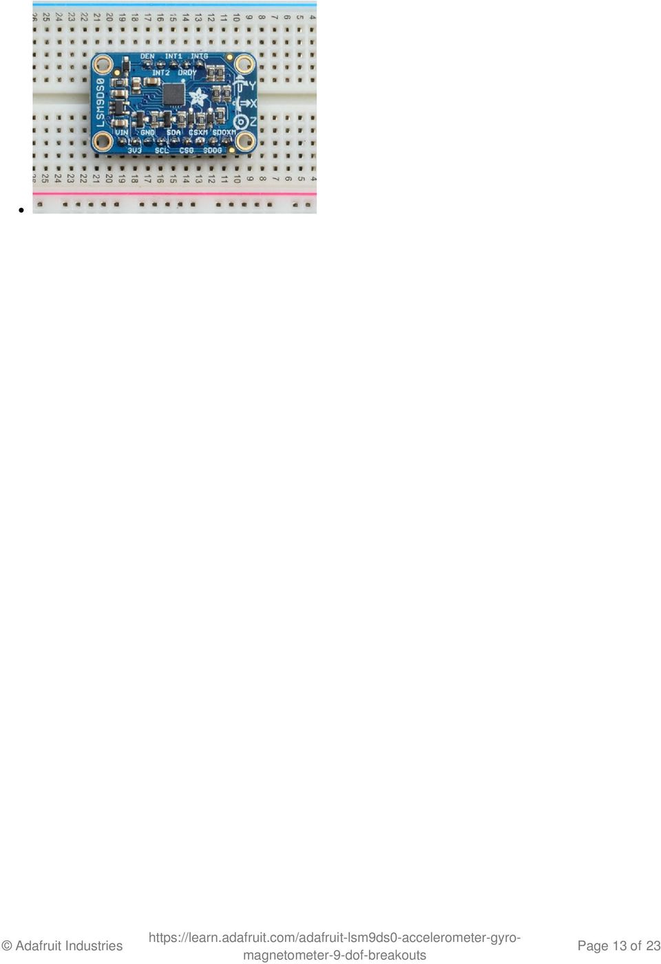
9 Interrupt & Misc Pins Since there's so many sensors in the LSM9DS0, there's quite a number of interrupt outputs. DEN - this is a pin that can be used to dynamically enable/disable the Gyro. There's actually no documentation on it but it seems you can try it out by enabling the trigger with write8(gyrotype, 0x21, 0xC0); which will let you use DEN to turn on/off gyro output (level trigger). This pin is level shifted. INT1 & INT2 - These are interrupts from the accelerometer/magnetometer subchip. We don't have specific library support for these so check the datasheet for what you can make these indicate. They are 3V-logic outputs DRDY - this is the Gyro subchip data ready output. We don't have specific library support for these so check the datasheet for how you can set the registers to enable this pin. It is a 3V-logic output. INTG - This is the interrupt from the Gyro subchip. We don't have specific library support for it so check the datasheet for what you can make it indicate. It is a 3V-logic output. Page 9 of 23

10 Assembly If you have the breadboard version of this sensor, you'll want to solder some header onto the sensor so it can be used in a breadboard. The Flora version does not require any extra assembly Prepare the header strip: Cut the strip to length if necessary. It will be easier to solder if you insert it into a breadboard - long pins down Add the breakout board: Place the breakout board over the pins so that the short pins Page 10 of 23

11 poke through the breakout pads And Solder! Be sure to solder all pins for reliable electrical contact. Solder the longer power/data strip first (For tips on soldering, be sure to check out our Guide to Excellent Soldering ( Page 11 of 23

12 If you plan to use the interrupts and/or you want the board to sit flatter in a breadboard, solder up the other strip! You're done! Check your solder joints visually and continue onto the next steps Page 12 of 23

13 Page 13 of 23
14 Wiring & Test Wiring for Flora Flora uses conductive thread or aligator clips, connect up the 3V/SDA/SCL/GND pins to the matching pins in the northwest quarter of the Flora board. We suggest alligator clips to test, then sew in with thread once it works! Wiring for Arduino You can easily wire this breakout to any microcontroller, we'll be using an Arduino. For another kind of microcontroller, just make sure it has I2C or SPI, then port the code - its pretty simple stuff! Let's start with just I2C interfacing since it requires the fewest # of wires: Page 14 of 23

15 Connect Vin to the power supply, 3-5V is fine. Use the same voltage that the microcontroller logic is based off of. For most Arduinos, that is 5V Connect GND to common power/data ground Connect the SCL pin to the I2C clock SCL pin on your Arduino. On an UNO & '328 based Arduino, this is also known as A5, on a Mega it is also known as digital 21 and on a Leonardo/Micro, digital 3 Connect the SDA pin to the I2C data SDA pin on your Arduino. On an UNO & '328 based Arduino, this is also known as A4, on a Mega it is also known as digital 20 and on a Leonardo/Micro, digital 2 Download Adafruit_LSM9DS0 To begin reading sensor data, you will need to download the Adafruit_LSM9DS0 Library from our github repository ( You can do that by visiting the github repo and manually downloading or, easier, just click this button to download the zip Download Adafruit_LSM9DS0 Library Rename the uncompressed folder Adafruit_LSM9DS0 and check that the Adafruit_LSM9DS0 folder contains Adafruit_LSM9DS0.cpp and Adafruit_LSM9DS0.h Place the Adafruit_LSM9DS0 library folder your arduinosketchfolder/libraries/ folder. You may need to create the libraries subfolder if its your first library. Restart the IDE. We also have a great tutorial on Arduino library installation at: ( Download Adafruit_Sensor The Adafruit_LSM9DS0 library uses the Adafruit_Sensor support backend so that readings can be normalized between sensors. You can grab Adafruit_Sensor from the github repo ( or just click the button below. Page 15 of 23

16 Download Adafruit_Sensor Library Install like you did with Adafruit_LSM9DS0 Restart the IDE! Load Demo Sketch Now you can open up File->Examples->Adafruit_LSM9DS0->lsm9doftest and upload to your Arduino wired up to the sensor Then open up the Serial console at 9600 baud to read the raw data output in 'counts'. This is data directly from the sensor, and isn't in any particular units. Page 16 of 23


17 This output is not terribly useful for most people - its simpler but does not have adjusted output units. Instead, we suggest the sensorapi demo. Upload that to the Arduino and open up the Serial console again. This time, you'll get the outputs in m/s*s, gauss an degrees-per-second Page 17 of 23


18 We suggest using this Adafruit_Sensor interface version, since it will let you swap sensors without having to worry about units compatibility. Try twisting and moving the board around to see the sensors change value. Library Reference The library we have is simple and easy to use You can create the Adafruit_LSM9DS0 object with: Adafruit_LSM9DS0 lsm = Adafruit_LSM9DS0(); // i2c sensor I2C does not have pins, as they are fixed in hardware. If you're using "hardware" SPI, you will have to wire up the pins as follows: SCL -> SPI CLK SDA -> SPI MOSI SDO_XM & SDO_G -> SPI MISO (both together) You can determine the hardware SPI pins for your Arduino here( Then pick two pins for the CS lines Adafruit_LSM9DS0 lsm = Adafruit_LSM9DS0(LSM9DS0_XM_CS, LSM9DS0_GYRO_CS); If you don't want to use the hardware SPI, you can also try the soft SPI capability, which is bitbanged. You can basically use any pins you like! Adafruit_LSM9DS0 lsm = Adafruit_LSM9DS0(LSM9DS0_SCLK, LSM9DS0_MISO, LSM9DS0_MOSI, LSM9DS0_XM_CS, LSM9DS0_GYRO_CS); Begin! To initialize the sensor, call lsm.begin() which will check the sensor can be found. It returns true/false depending on Page 18 of 23

19 these checks. We suggest you wrap begin() in a statement that will check if the sensor was located: if(!lsm.begin()) { /* There was a problem detecting the LSM9DS0... check your connections */ Serial.print(F("Ooops, no LSM9DS0 detected... Check your wiring!")); while(1); } Set Ranges These chips have tons of registers, we basically provide interface code for the most useful stuff, such as setting the range. Each subsensor has it's own range. Higher ranges have less precision but can measure larger movements! Set up the ranges with the setup functions: // 1.) Set the accelerometer range lsm.setupaccel(lsm.lsm9ds0_accelrange_2g); //lsm.setupaccel(lsm.lsm9ds0_accelrange_4g); //lsm.setupaccel(lsm.lsm9ds0_accelrange_6g); //lsm.setupaccel(lsm.lsm9ds0_accelrange_8g); //lsm.setupaccel(lsm.lsm9ds0_accelrange_16g); // 2.) Set the magnetometer sensitivity lsm.setupmag(lsm.lsm9ds0_maggain_2gauss); //lsm.setupmag(lsm.lsm9ds0_maggain_4gauss); //lsm.setupmag(lsm.lsm9ds0_maggain_8gauss); //lsm.setupmag(lsm.lsm9ds0_maggain_12gauss); // 3.) Setup the gyroscope lsm.setupgyro(lsm.lsm9ds0_gyroscale_245dps); //lsm.setupgyro(lsm.lsm9ds0_gyroscale_500dps); //lsm.setupgyro(lsm.lsm9ds0_gyroscale_2000dps); Choose whichever range you like, after you begin() the sensor! Read data Read data using the Adafruit_Sensor API by first creating four events, one for each sub-sensor: sensors_event_t accel, mag, gyro, temp; Then pass these into the getevent function lsm.getevent(&accel, &mag, &gyro, &temp); The data is snapshotted at once, so you can read and manage the data later. For the Accelerometer event you can read accel.acceleration.x, accel.acceleration.y or accel.acceleration.z which are in meters/second*second. For the Magnetometer event you can read mag.magnetic.x, mag.magnetic.y or mag.magnetic.z which are in gauss. For the Gyro event you can read gyro.gyro.x, gyro.gyro.y or gyro.gyro.z, which are in degrees-per-second (dps) The temperature event data is in temp.temperature, in degrees C Page 19 of 23
 Set the accelerometer range lsm.setupaccel(lsm.lsm9ds0_accelrange_2g); //lsm.")
20 FAQs Why is the temperature value weird on my LSM9DSO? While there is a temperature sensor inside the LSM9DSO, unfortunately there isn't enough information provided in the datasheet to properly interpret or convert the values. We've made our best guess at interpreting the data, but you may need to incorporate an external temperature sensor if you require accurate temperature values in your system. This is a known and long-standing issue with this sensor (example ( and to our knowledge ST has never addressed it or provided the extra information needed to accurately interpret the raw temperature data. Page 20 of 23

21 Downloads Datasheets LSM9DS0 Datasheet ( Breakout EagleCAD PCB files on GitHub ( Flora EagleCAD PCB files on GitHub ( Fritzing objects available in Adafruit Fritzing library ( Breakout Board Schematic Breakout Board PCB Print Dimensions in Inches Page 21 of 23
22 Flora Breakout Schematics Flora Breakout PCB Print Dimensions in Inches Page 22 of 23

23 Last Updated: :27:17 PM UTC Page 23 of 23
Adafruit MCP9808 Precision I2C Temperature Sensor Guide
 Adafruit MCP9808 Precision I2C Temperature Sensor Guide Created by lady ada Last updated on 2014-04-22 03:01:18 PM EDT Guide Contents Guide Contents Overview Pinouts Power Pins I2C Data Pins Optional Pins
Adafruit SHT31-D Temperature & Humidity Sensor Breakout
 Adafruit SHT31-D Temperature & Humidity Sensor Breakout Created by lady ada Last updated on 2016-06-23 10:13:40 PM EDT Guide Contents Guide Contents Overview Pinouts Power Pins: I2C Logic pins: Other Pins:
Adafruit BME280 Humidity + Barometric Pressure + Temperature Sensor Breakout
 Adafruit BME280 Humidity + Barometric Pressure + Temperature Sensor Breakout Created by lady ada Last updated on 2016-04-26 12:01:06 PM EDT Guide Contents Guide Contents Overview Pinouts Power Pins: SPI
Adafruit ATWINC1500 WiFi Breakout
 Adafruit ATWINC1500 WiFi Breakout Created by lady ada Last updated on 2016-06-15 03:48:57 PM EDT Guide Contents Guide Contents Overview Pinouts Power Pins SPI Pins Other SPI Interface Pins Assembly Prepare
TSL2561 Luminosity Sensor
 TSL2561 Luminosity Sensor Created by lady ada Last updated on 2015-06-12 12:10:28 PM EDT Guide Contents Guide Contents Overview Wiring the TSL2561 Sensor Using the TSL2561 Sensor Downloads Buy a TSL2561
Adafruit Si4713 FM Radio Transmitter with RDS/RDBS Support
 Adafruit Si4713 FM Radio Transmitter with RDS/RDBS Support Created by lady ada Last updated on 2014-07-09 11:00:12 AM EDT Guide Contents Guide Contents Overview Pinouts Audio Inputs Power Pins Interface
1.8" TFT Display Breakout and Shield
 1.8" TFT Display Breakout and Shield Created by lady ada Last updated on 2015-04-09 03:48:28 PM EDT Guide Contents Guide Contents Overview Breakout Pinouts Breakout Assembly Prepare the header strip: Add
2.2" TFT Display. Created by Ladyada. Last updated on 2014-03-31 12:15:09 PM EDT
 2.2" TFT Display Created by Ladyada Last updated on 2014-03-31 12:15:09 PM EDT Guide Contents Guide Contents Overview Connecting the Display Test the Display Graphics Library Bitmaps Alternative Wiring
1.5" & 2.1" Monochrome 128x64 OLED Display Module
 1.5" & 2.1" Monochrome 128x64 OLED Display Module Created by lady ada Last updated on 2016-02-16 11:27:52 AM EST Guide Contents Guide Contents Overview Pinouts Power Pins Signal Pins Remaining Pins Assembly
2.3" Monochrome 128x32 OLED Display Module
 2.3" Monochrome 128x32 OLED Display Module Created by lady ada Last updated on 2016-03-27 06:56:07 AM EDT Guide Contents Guide Contents Overview Pinouts Power Pins Signal Pins Remaining Pins Assembly Changing
Tiny Arduino Music Visualizer
 Tiny Arduino Music Visualizer Created by Phillip Burgess Last updated on 2014-04-17 09:30:35 PM EDT Guide Contents Guide Contents Overview Wiring Code Troubleshooting Principle of Operation Ideas 2 3 4
A REST API for Arduino & the CC3000 WiFi Chip
 A REST API for Arduino & the CC3000 WiFi Chip Created by Marc-Olivier Schwartz Last updated on 2014-04-22 03:01:12 PM EDT Guide Contents Guide Contents Overview Hardware configuration Installing the library
DS1307 Real Time Clock Breakout Board Kit
 DS1307 Real Time Clock Breakout Board Kit Created by Tyler Cooper Last updated on 2015-10-15 11:00:14 AM EDT Guide Contents Guide Contents Overview What is an RTC? Parts List Assembly Arduino Library Wiring
Arduino ADK Back. For information on using the board with the Android OS, see Google's ADK documentation.
 Arduino ADK Arduino ADK R3 Front Arduino ADK R3 Back Arduino ADK Front Arduino ADK Back Overview The Arduino ADK is a microcontroller board based on the ATmega2560 (datasheet). It has a USB host interface
PN532 NFC RFID Module User Guide
 PN532 NFC RFID Module User Guide Version 3 Introduction NFC is a popular technology in recent years. We often heard this word while smart phone company such as Samsung or HTC introduces their latest high-end
Arduino Due Back. Warning: Unlike other Arduino boards, the Arduino Due board runs at 3.3V. The maximum. Overview
 R Arduino Due Arduino Due Front Arduino Due Back Overview The Arduino Due is a microcontroller board based on the Atmel SAM3X8E ARM Cortex-M3 CPU (datasheet). It is the first Arduino board based on a 32-bit
Adafruit Proto Shield for Arduino
 Adafruit Proto Shield for Arduino Created by lady ada Last updated on 2016-08-04 11:06:30 PM UTC Guide Contents Guide Contents Overview Make it! Lets go! Preparation Prep Tools Parts list Parts List Optional
Application Note IMU Visualization Software
 ECE 480 Spring 2013 Team 8 Application Note IMU Visualization Software Name: Alex Mazzoni Date: 04/04/2013 Facilitator: Dr. Aviyente Abstract This application note covers how to use open source software
MCP4725 Digital to Analog Converter Hookup Guide
 Page 1 of 9 MCP4725 Digital to Analog Converter Hookup Guide CONTRIBUTORS: JOELEB To DAC, or Not to DAC... When learning about the world of microcontrollers, you will come across analog-to-digital converters
Hardware Connections between Arduino and IMU Nori Wilkins Apr. 5, 2013
 Hardware Connections between Arduino and IMU Nori Wilkins Apr. 5, 2013 Abstract Sensors are commonly used throughout many world wide applications. Out of many sensors that are used, the inertial measurement
AR1100 Resistive Touch Screen Controller Guide
 AR1100 Resistive Touch Screen Controller Guide Created by lady ada Last updated on 2015-06-30 01:40:06 PM EDT Guide Contents Guide Contents Overview Calibrating the AR1100 Download and Install AR1100 Configuration
ARDUINO SEVERINO SERIAL SINGLE SIDED VERSION 3 S3v3 (REVISION 2) USER MANUAL
 USER MANUAL") ARDUINO SEVERINO SERIAL SINGLE SIDED VERSION 3 S3v3 (REVISION 2) USER MANUAL X1: DE-9 serial connector Used to connect computer (or other devices) using RS-232 standard. Needs a serial cable, with at least
ARDUINO SEVERINO SERIAL SINGLE SIDED VERSION 3 S3v3 (REVISION 2) USER MANUAL X1: DE-9 serial connector Used to connect computer (or other devices) using RS-232 standard. Needs a serial cable, with at least
DATASHEET. ADAM Arduino Display Adaptor Module. Arduino Compatible Shield P/N: 4Display-Shield-FT843 For the 4D Systems 4DLCD-FT843 Display
 DATASHEET ADAM Arduino Display Adaptor Module Arduino Compatible Shield P/N: 4Display-Shield-FT843 For the 4D Systems 4DLCD-FT843 Display Document Date: 8 th January 2014 Document Revision: 1.0 Uncontrolled
Adafruit Music Maker Shield
 Adafruit Music Maker Shield Created by lady ada Last updated on 2015-10-09 02:10:09 PM EDT Guide Contents Guide Contents Overview Pinouts Main Control Breakouts SPI Jumpers GPIO Breakouts MicroSD Card
WICE-SPI Hardware Operation Manual
 Contents 1.Hardware Instruction...1 2. Pin Definition Of WICE-SPI Connector...2 3. Peripheral Circuit Arrangements...3 4. On-Board Programming...4 5. Off-Line Programming...8 1.Hardware Instruction 1.WICE-SPI
INTRODUCTION TO SERIAL ARM
 INTRODUCTION TO SERIAL ARM A robot manipulator consists of links connected by joints. The links of the manipulator can be considered to form a kinematic chain. The business end of the kinematic chain of
Data Sheet. Adaptive Design ltd. Arduino Dual L6470 Stepper Motor Shield V1.0. 20 th November 2012. L6470 Stepper Motor Shield
 Arduino Dual L6470 Stepper Motor Shield Data Sheet Adaptive Design ltd V1.0 20 th November 2012 Adaptive Design ltd. Page 1 General Description The Arduino stepper motor shield is based on L6470 microstepping
TEECES DOME LIGHTING SYSTEMS
 This lighting system was designed by John V (Teeces) to be a simple, customizable, expandable and affordable solution for dome lighting. An Arduino micro-controller is used to tell LED driver chips which
Arduino DUE + DAC MCP4922 (SPI)
") Arduino DUE + DAC MCP4922 (SPI) v101 In this document it will described how to connect and let a Digital/Analog convert work with an Arduino DUE. The big difference between and Arduino DUE and other Arduinos
Arduino DUE + DAC MCP4922 (SPI) v101 In this document it will described how to connect and let a Digital/Analog convert work with an Arduino DUE. The big difference between and Arduino DUE and other Arduinos
Eric Mitchell April 2, 2012 Application Note: Control of a 180 Servo Motor with Arduino UNO Development Board
 Eric Mitchell April 2, 2012 Application Note: Control of a 180 Servo Motor with Arduino UNO Development Board Abstract This application note is a tutorial of how to use an Arduino UNO microcontroller to
CAN-Bus Shield Hookup Guide
 Page 1 of 8 CAN-Bus Shield Hookup Guide Introduction The CAN-Bus Shield provides your Arduino or Redboard with CAN-Bus capabilities and allows you to hack your vehicle! CAN-Bus Shield connected to a RedBoard.
Designing VM2 Application Boards
 Designing VM2 Application Boards This document lists some things to consider when designing a custom application board for the VM2 embedded controller. It is intended to complement the VM2 Datasheet. A
Adafruit LED Backpacks
 Adafruit LED Backpacks Created by lady ada Last updated on 2016-03-18 12:05:32 AM EDT Guide Contents Guide Contents Overview 1.2" 8x8 Matrix (http://adafru.it/apt)mini 8x8 Matrix Software 0.8" 8x8 Matrix
Wireless Security Camera with the Arduino Yun
 Wireless Security Camera with the Arduino Yun Created by Marc-Olivier Schwartz Last updated on 2014-08-13 08:30:11 AM EDT Guide Contents Guide Contents Introduction Connections Setting up your Temboo &
InvenSense Motion Sensor Universal Evaluation Board (UEVB) User Guide
 User Guide") Application Note InvenSense Motion Sensor Universal Evaluation Board (UEVB) User Guide PURPOSE This document describes the hardware and circuitry on the Universal Evaluation Board (UEVB). The UEVB is used
Application Note InvenSense Motion Sensor Universal Evaluation Board (UEVB) User Guide PURPOSE This document describes the hardware and circuitry on the Universal Evaluation Board (UEVB). The UEVB is used
Building a Basic Communication Network using XBee DigiMesh. Keywords: XBee, Networking, Zigbee, Digimesh, Mesh, Python, Smart Home
 Building a Basic Communication Network using XBee DigiMesh Jennifer Byford April 5, 2013 Keywords: XBee, Networking, Zigbee, Digimesh, Mesh, Python, Smart Home Abstract: Using Digi International s in-house
RGB LED Strips. Created by lady ada. Last updated on 2015-12-07 12:00:18 PM EST
 RGB LED Strips Created by lady ada Last updated on 2015-12-07 12:00:18 PM EST Guide Contents Guide Contents Overview Schematic Current Draw Wiring Usage Example Code Support Forums 2 3 5 6 7 10 12 13 Adafruit
Arduino Lesson 13. DC Motors. Created by Simon Monk
 Arduino Lesson 13. DC Motors Created by Simon Monk Guide Contents Guide Contents Overview Parts Part Qty Breadboard Layout Arduino Code Transistors Other Things to Do 2 3 4 4 4 6 7 9 11 Adafruit Industries
User s Manual of Board Microcontroller ET-MEGA2560-ADK ET-MEGA2560-ADK
 User s Manual of Board Microcontroller ET-MEGA2560-ADK ET-MEGA2560-ADK Because Arduino that is the development project on AVR MCU as Open Source has been published, it is popular and widespread shortly.
Surveillance System Using Wireless Sensor Networks
 Surveillance System Using Wireless Sensor Networks Dan Nguyen, Leo Chang Computer Engineering, Santa Clara University Santa Clara, California, USA dantnguyen84@gmail.com chihshun@gmail.com Abstract The
Character LCDs. Created by Ladyada. Last updated on 2013-07-26 02:45:29 PM EDT
 Character LCDs Created by Ladyada Last updated on 2013-07-26 02:45:29 PM EDT Guide Contents Guide Contents Overview Character vs. Graphical LCDs LCD Varieties Wiring a Character LCD Installing the Header
Pololu DRV8835 Dual Motor Driver Shield for Arduino
 Pololu DRV8835 Dual Motor Driver Shield for Arduino Pololu DRV8835 Dual Motor Driver Shield for Arduino, bottom view with dimensions. Overview This motor driver shield and its corresponding Arduino library
Model 201 Wiegand Touchpad Reader Installation Guide
 Model 201 Wiegand Touchpad Reader Installation Guide P/N 460353001C 15AUG11 2011 UTC Fire & Security. All rights reserved. This document may not be copied in whole or in part or otherwise reproduced without
UniPi technical documentation REV 1.1
 technical documentation REV 1.1 Contents Overview... 2 Description... 3 GPIO port map... 4 Power Requirements... 5 Connecting Raspberry Pi to UniPi... 5 Building blocks... 5 Relays... 5 Digital Inputs...
Thermistor. Created by Ladyada. Last updated on 2013-07-26 02:30:46 PM EDT
 Thermistor Created by Ladyada Last updated on 2013-07-26 02:30:46 PM EDT Guide Contents Guide Contents Overview Some Stats Testing a Thermistor Using a Thermistor Connecting to a Thermistor Analog Voltage
The self-starting solar-powered Stirling engine
 The self-starting solar-powered Stirling engine This project began at the request of an artist who had proposed a Stirling-engine-powered sculpture to a client. The engine only had to run, not really produce
Board also Supports MicroBridge
 This product is ATmega2560 based Freeduino-Mega with USB Host Interface to Communicate with Android Powered Devices* like Android Phone or Tab using Android Open Accessory API and Development Kit (ADK)
+Denotes lead-free and RoHS-compliant. C5 C10, C17, C18
 19-0623; Rev 1; 3/08 Maxim MINIQUSB User Guide General Description The Maxim command module (MINIQUSB) receives commands from a PC through the USB to create an SPI or SMBus /I 2 C-compatible interface.
PIR Motion Sensor. Created by Ladyada. Last updated on 2014-01-28 06:15:25 PM EST
 PIR Motion Sensor Created by Ladyada Last updated on 2014-01-28 06:15:25 PM EST Guide Contents Guide Contents Overview Some Basic Stats How PIRs Work The PIR Sensor Lenses Connecting to a PIR Testing a
Arduino Lesson 16. Stepper Motors
 Arduino Lesson 16. Stepper Motors Created by Simon Monk Last updated on 2013-11-22 07:45:14 AM EST Guide Contents Guide Contents Overview Parts Part Qty Breadboard Layout Arduino Code Stepper Motors Other
Adding a Real Time Clock to Raspberry Pi
 Adding a Real Time Clock to Raspberry Pi Created by lady ada Last updated on 2016-04-29 11:45:10 PM EDT Guide Contents Guide Contents Overview Wiring the RTC Set up I2C on your Pi Verify Wiring (I2C scan)
Part 1. MAX 525 12BIT DAC with an Arduino Board. MIDI to Voltage Converter Part1
 MIDI to Voltage Converter Part 1 MAX 525 12BIT DAC with an Arduino Board 1 What you need: 2 What you need : Arduino Board (Arduino Mega 2560) 3 What you need : Arduino Board (Arduino Mega 2560) Digital
3.2 inch Arduino LCD Shield User Guide
 Rev 2.0, Nov 2012 Table of Contents 1 Introduction... 3 2 Features... 3 3 Specifications... 3 4 Pin Definition... 4 5 Fimware library... 4 6 FAQs... 4 Revision History Revision Description Confirm by V1.0
Lab 3: PCB design with EAGLE
 In this lab you will design a PCB board that will replace all the wires and boards you ve used in the first two labs. 1. Pre-Lab On the website are two EAGLE tutorials. Do them both. Q1. For the first
How to Move Canon EF Lenses. Yosuke Bando
 How to Move Canon EF Lenses Yosuke Bando Preface This instruction is intended to be helpful to those who are interested in making modifications to camera lenses to explore/reproduce focus sweep, focal
Murata MEMS Evaluation Unit User Manual
 Murata MEMS Evaluation Murata Electronics Oy Subject to changes 1/34 TABLE OF CONTENTS 1 Introduction... 4 2 Quick start for using the Murata MEMS Evaluation Unit... 4 3 Hardware overview... 5 4 Installation...
Project Plan. Project Plan. May13-06. Logging DC Wattmeter. Team Member: Advisor : Ailing Mei. Collin Christy. Andrew Kom. Client: Chongli Cai
 Project Plan May13-06 Logging DC Wattmeter Team Member: Ailing Mei Andrew Kom Chongli Cai Advisor : Collin Christy Client: Garmin International David Hoffman Qiaoya Cui Table of Contents Need Statement...
Hand Gestures Remote Controlled Robotic Arm
 Advance in Electronic and Electric Engineering. ISSN 2231-1297, Volume 3, Number 5 (2013), pp. 601-606 Research India Publications http://www.ripublication.com/aeee.htm Hand Gestures Remote Controlled
Arduino Lesson 14. Servo Motors
 Arduino Lesson 14. Servo Motors Created by Simon Monk Last updated on 2013-06-11 08:16:06 PM EDT Guide Contents Guide Contents Overview Parts Part Qty The Breadboard Layout for 'Sweep' If the Servo Misbehaves
Pmod peripheral modules are powered by the host via the interface s power and ground pins.
 Digilent Pmod Interface Specification Revision: November 20, 2011 1300 NE Henley Court, Suite 3 Pullman, WA 99163 (509) 334 6306 Voice (509) 334 6300 Fax Introduction The Digilent Pmod interface is used
DSO138 oscilloscope program upgrade method
 DSO138 oscilloscope program upgrade method Applicable models: 13801K, 13802K Program upgrade Principle The DSO138 is a SCM STM32F103C8 internal oscilloscope that is preinstalled with a flash bootloader,
RS232/DB9 An RS232 to TTL Level Converter
 RS232/DB9 An RS232 to TTL Level Converter The RS232/DB9 is designed to convert TTL level signals into RS232 level signals. This cable allows you to connect a TTL level device, such as the serial port on
How to Make a Pogo Pin Test Jig. Created by Tyler Cooper
 How to Make a Pogo Pin Test Jig Created by Tyler Cooper Guide Contents Guide Contents Overview Preparation Arduino Shield Jigs The Code Testing Advanced Pogo Jigs Support Forums 2 3 4 6 9 11 12 13 Adafruit
MODULE BOUSSOLE ÉLECTRONIQUE CMPS03 Référence : 0660-3
 MODULE BOUSSOLE ÉLECTRONIQUE CMPS03 Référence : 0660-3 CMPS03 Magnetic Compass. Voltage : 5v only required Current : 20mA Typ. Resolution : 0.1 Degree Accuracy : 3-4 degrees approx. after calibration Output
MARTECH SPI Tools. MARTECH SPI Tools User Manual v1.0. User Manual
 MARTECH SPI Tools v1.0 Contents 1. Basic informations about the product...3 1.1 Memory types supported by SPI Tool...3 2. Main features and application possibilities...4 2.1 Technical Support activation...4
2.8" TFT Touchscreen. Created by lady ada. Last updated on 2014-12-11 12:00:25 PM EST
 2.8" TFT Touchscreen Created by lady ada Last updated on 2014-12-11 12:00:25 PM EST Guide Contents Guide Contents Overview Connection Options Mounting Options Backlight Wiring TFT Wiring LCD Test Graphics
Bluetooth + USB 16 Servo Controller [RKI-1005 & RKI-1205]
![Bluetooth + USB 16 Servo Controller [RKI-1005 & RKI-1205]](/thumbs/40/21161302.jpg "Bluetooth + USB 16 Servo Controller [RKI-1005 & RKI-1205]") Bluetooth + USB 16 Servo Controller [RKI-1005 & RKI-1205] Users Manual Robokits India info@robokits.co.in http://www.robokitsworld.com Page 1 Bluetooth + USB 16 Servo Controller is used to control up to
Bluetooth + USB 16 Servo Controller [RKI-1005 & RKI-1205] Users Manual Robokits India info@robokits.co.in http://www.robokitsworld.com Page 1 Bluetooth + USB 16 Servo Controller is used to control up to
Web Site: www.parallax.com Forums: forums.parallax.com Sales: sales@parallax.com Technical: support@parallax.com
 Web Site: www.parallax.com Forums: forums.parallax.com Sales: sales@parallax.com Technical: support@parallax.com Office: (916) 624-8333 Fax: (916) 624-8003 Sales: (888) 512-1024 Tech Support: (888) 997-8267
PCAN-MicroMod Universal I/O Module with CAN Interface. User Manual. Document version 2.1.0 (2014-01-16)
") PCAN-MicroMod Universal I/O Module with CAN Interface User Manual Document version 2.1.0 (2014-01-16) Products taken into account Product Name Part number Model PCAN-MicroMod IPEH-002080 with firmware
PCAN-MicroMod Universal I/O Module with CAN Interface User Manual Document version 2.1.0 (2014-01-16) Products taken into account Product Name Part number Model PCAN-MicroMod IPEH-002080 with firmware
AXE114S BINARY CLOCK. revolution Revolution Education Ltd. Email: info@rev-ed.co.uk Web: www.rev-ed.co.uk Version 1.1 12/09/08 AXE114.PMD.
 AXE114S BINARY CLOCK Features: The PICAXE binary clock kit tells the time by lighting up blue LEDs in a binary pattern. This is a useful tool for teaching students binary code or simply just confusing/
IR Communication a learn.sparkfun.com tutorial
 IR Communication a learn.sparkfun.com tutorial Available online at: http://sfe.io/t33 Contents Getting Started IR Communication Basics Hardware Setup Receiving IR Example Transmitting IR Example Resources
2013 G Miller. 3 Axis Brushless Gimbal Controller Manual
 2013 G Miller 3 Axis Brushless Gimbal Controller Manual P a g e 2 When you receive your 3 axis controller board from dys.hk in the packet will be the following items the sensor 3rd Axis board the main
Web Site: www.parallax.com Forums: forums.parallax.com Sales: sales@parallax.com Technical: support@parallax.com
 Web Site: www.parallax.com Forums: forums.parallax.com Sales: sales@parallax.com Technical: support@parallax.com Office: (916) 624-8333 Fax: (916) 624-8003 Sales: (888) 512-1024 Tech Support: (888) 997-8267
MXL5007T TUNER RADIO
 MXL5007T TUNER RADIO MxL5007T is a tuner IC designed mostly for digital signals (DVB-T, ATSC), but it can be used for analog reception too. It has a programmable IF output and it can receive anything from
RC2200DK Demonstration Kit User Manual
 Demonstration Kit User Manual Table of contents TABLE OF CONTENTS... 1 QUICK INTRODUCTION... 2 INTRODUCTION... 3 DEMONSTRATION BOARD... 4 POWER SUPPLY SECTION... 5 RS-232 INTERFACE... 6 CONNECTORS... 7
Introducing AVR Dragon
 Introducing AVR Dragon ' Front Side Back Side With the AVR Dragon, Atmel has set a new standard for low cost development tools. AVR Dragon supports all programming modes for the Atmel AVR device family.
Build Instructions for TempBug: Internet-Connected Thermometer Step 1: Gather the parts
 Build Instructions for TempBug: Internet-Connected Thermometer Step 1: Gather the parts Take a look at the bill of materials for this project to see all the parts youʼll need and where you can get them.
LCD I 2 C/Serial RX Backpack. Data Sheet. LCD to I2C/Serial RX Backpack I2C or Serial RX communication with Standard 16 Pin LCD modules
 LCD I 2 C/Serial RX Backpack Data Sheet LCD to I2C/Serial RX Backpack I2C or Serial RX communication with Standard 16 Pin LCD modules Version 203 Sep 2013 Contents Contents 2 Introduction3 Voltage Levels3
MicroMag3 3-Axis Magnetic Sensor Module
 1008121 R01 April 2005 MicroMag3 3-Axis Magnetic Sensor Module General Description The MicroMag3 is an integrated 3-axis magnetic field sensing module designed to aid in evaluation and prototyping of PNI
DKWF121 WF121-A 802.11 B/G/N MODULE EVALUATION BOARD
 DKWF121 WF121-A 802.11 B/G/N MODULE EVALUATION BOARD PRELIMINARY DATA SHEET Wednesday, 16 May 2012 Version 0.5 Copyright 2000-2012 Bluegiga Technologies All rights reserved. Bluegiga Technologies assumes
Bluetooth UART/RS232 Module
 Introduction BLUEMORE600 is a professional, slim, wireless module ready for integration in brand new or existing electronic products. Based on CSR chipset BC03MM it s fully compatible for Serial Port profiles.
Using the Adafruit Unified Sensor Driver. Created by Kevin Townsend
 Using the Adafruit Unified Sensor Driver Created by Kevin Townsend Guide Contents Guide Contents Introduction One Type to Rule Them All Why Is This a Good Thing? Adafruit_Sensor in Detail Standardised
Arduino Lesson 1. Blink
 Arduino Lesson 1. Blink Created by Simon Monk Last updated on 2015-01-15 09:45:38 PM EST Guide Contents Guide Contents Overview Parts Part Qty The 'L' LED Loading the 'Blink' Example Saving a Copy of 'Blink'
SainSmart UNO R3 Starter Kit
 SainSmart UNO R3 Starter Kit //SainSmart UNO R3 The SainSmart UNO R3 is one of several development boards based on the ATmega328-AU. We like it mainly because of its extensive support network and its versatility.
Arduino Lab 1 - The Voltage Divider
 Arduino Lab 1 - The Voltage Divider 1. Introduction In this lab, we will endanger a cute animal, create a portal to another dimension, and invent a new genre of music. Along the way, we will learn about
USB / Data-Acquisition Module NOW LEAD-FREE
 USB / Data-Acquisition Module NOW LEAD-FREE DLP-TEMP-G Features: Digital I/Os, Analog Inputs (0- Volts) or any combination USB. and.0 Compatible Interface th Generation Silicon from FTDI Supports Up To
Flight Controller. Mini Fun Fly
 Flight Controller Mini Fun Fly Create by AbuseMarK 0 Mini FunFly Flight Controller Naze ( Introduction 6x6mm. 6 grams (no headers, 8 grams with). 000 degrees/second -axis MEMS gyro. auto-level capable
Real Time Clock USB Evaluation Board V3.0
 Real Time Clock USB Evaluation Board V.0 Application Note February 9, 008 RTC EVB Intersil RTC Devices Supported Introduction This evaluation board provides a platform for testing Intersil Real Time Clock
Adafruit's Raspberry Pi Lesson 1. Preparing an SD Card for your Raspberry Pi
 Adafruit's Raspberry Pi Lesson 1. Preparing an SD Card for your Raspberry Pi Created by Simon Monk Last updated on 2015-11-25 11:50:13 PM EST Guide Contents Guide Contents Overview You Will Need Downloading
Embedded Systems Design Course Applying the mbed microcontroller
 Embedded Systems Design Course Applying the mbed microcontroller Serial communications with SPI These course notes are written by R.Toulson (Anglia Ruskin University) and T.Wilmshurst (University of Derby).
Arduino Lesson 0. Getting Started
 Arduino Lesson 0. Getting Started Created by Simon Monk Last updated on 204-05-22 2:5:0 PM EDT Guide Contents Guide Contents Overview Parts Part Qty Breadboard Installing Arduino (Windows) Installing Arduino
Adafruit CC3000 WiFi. Created by Rick Lesniak. Last updated on 2014-07-17 01:30:11 PM EDT
 Adafruit CC3000 WiFi Created by Rick Lesniak Last updated on 2014-07-17 01:30:11 PM EDT Guide Contents Guide Contents Overview Assembly and Wiring CC3000 Breakout Assembly Wiring CC3000 Shield Assembly
TOSR0X-D. USB/Wireless Timer Relay Module. User Manual. Tinysine Electronics @ 2013 Version 1.0
 TOSR0X-D USB/Wireless Timer Relay Module User Manual Tinysine Electronics @ 2013 Version 1.0 INTRODUCTION This USB/Wireless Timer Relay Module allows computer control switching of external devices by using
Web Site: www.parallax.com Forums: forums.parallax.com Sales: sales@parallax.com Technical: support@parallax.com
 Web Site: www.parallax.com Forums: forums.parallax.com Sales: sales@parallax.com Technical: support@parallax.com Office: (916) 624-8333 Fax: (916) 624-83 Sales: (888) 512-124 Tech Support: (888) 997-8267
Green House Monitoring and Controlling Using Android Mobile Application
 Green House Monitoring and Controlling Using Android Mobile Application Aji Hanggoro aji.hanggoro@ui.ac.id Mahesa Adhitya Putra mahesa.adhitya91@ui.ac.id Rizki Reynaldo rizki.reynaldo@ui.ac.id Riri Fitri
Arduino Lesson 17. Email Sending Movement Detector
 Arduino Lesson 17. Email Sending Movement Detector Created by Simon Monk Last updated on 2014-04-17 09:30:23 PM EDT Guide Contents Guide Contents Overview Parts Part Qty Breadboard Layout Arduino Code
Matrix and 7-Segment LED Backpack with the Raspberry Pi
 Matrix and 7-Segment LED Backpack with the Raspberry Pi Created by Kevin Townsend Last updated on 2014-07-09 02:30:10 PM EDT Guide Contents Guide Contents Overview What You'll Need Related Information
Designing a Schematic and Layout in PCB Artist
 Designing a Schematic and Layout in PCB Artist Application Note Max Cooper March 28 th, 2014 ECE 480 Abstract PCB Artist is a free software package that allows users to design and layout a printed circuit
- 35mA Standby, 60-100mA Speaking. - 30 pre-defined phrases with up to 1925 total characters.
 Contents: 1) SPE030 speech synthesizer module 2) Programming adapter kit (pcb, 2 connectors, battery clip) Also required (for programming) : 4.5V battery pack AXE026 PICAXE download cable Specification:
FTDI Chip. VM800P Datasheet Embedded Video Engine Plus Module. VM800P Embedded Video Engine Plus Module Datasheet Version 1.0
 FTDI Chip VM800P Datasheet Embedded Video Engine Plus Module General Purpose Multi Media Controller The VM800P is a development module for FTDI s FT800, which is used to develop and demonstrate the functionality