Massachusetts Institute of Technology Department of Electrical Engineering and Computer Science Microprocessor Project Laboratory
|
|
|
- Charity Cooper
- 8 years ago
- Views:
Transcription
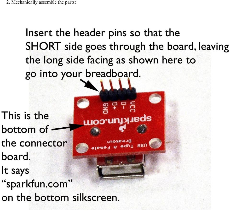
1 Massachusetts Institute of Technology Department of Electrical Engineering and Computer Science Microprocessor Project Laboratory Connecting your PSoC Evaluation Board It is easy and fun to avoid blowing up your PSoC board. Be careful with the board and it will serve you long after you have taken The most common reasons that a PSoC evaluation board is destroyed include: 1. The evaluation board is connected to an external IC, computer, or other device but there is no common ground connection between the two systems. 2. Excessive voltage is applied to an evaluation board pin. 3. Two different forms of power are applied to the board. Make CERTAIN that you have a common ground connection between your PSoC and your external components like your R31JP or lab kit. Make CERTAIN that you do NOT apply more than 5 volts to any 5 volt-rated PSoC pin, and do not mix 3.3 and 5 volt signals. If you do not understand these points, ASK us before experimenting with your evaluation board. To assist you in using your PSoC evaluation board with your lab kit, we will make a power cable for the PSoC board. If used correctly, this power cable will ensure that your PSoC is properly grounded to your kit. Let's construct a little demonstration that will show you how to use your PSoC Evaluation Board with the lab kit and the R31JP. Our plan is: The R31JP will emit a message at 9600 baud over it's normal RS232 serial connector (the same 9 pin D-Sub we use to connect to a PC through a serial cable.). The R31JP will be powered "as normal" over the Blackbird power cable. The transmitting program for the R31JP has been burned into the ROM, replacing MINMON with a transmitting program you can find on the course website. The PSoC evaluation board will be powered by 5 volts and ground from the Blackbird over a USB connector that you will add to your kit. A serial cable will connect the PSoC to the R31JP. The PSoC will receive the message from the R31JP and display this message on the PSoC Evaluation Board LCD. Begin by constructing a kit USB power connector that will allow you to use your kit to power the PSoC evaluation board.

2 Please begin here: 1. See Professor Leeb during office hours for header strip and a connector board, shown below.

3 2. Mechanically assemble the parts:
4 3. Solder the parts:

5 4. Install the connector board, bypass cap, power wiring, and PSoC USB Cable on your kit. Do NOT connect your PSoC evaluation board to anything yet.

6 5. Secure the USB cable when installed on your kit:

7 NOW STOP! Bring your kit to a staff member. Demonstrate that you have Vcc and GND connected to 5 volts. Do NOT plug in your PSOC evaluation board. Demonstrate that you have NOTHING connected to the D+ and D- pins on the power connector board. WITH A STAFF MEMBER, after verifying everything above, then plug in your PSOC evaluation board using the mini-usb connector farthest over on the board, as always: Make sure your PSOC evaluation board powers up.

8 Once your kit has been modified to provide USB power to the PSOC, you can now connect your PSOC to your R31JP using a serial cable and a NULL Modem connector: You can read about the "NULL modem" or "CROSS CABLE" here: The connection you are looking for is the simple "3-wire cross cable" described on this website. WE WILL HAVE NULL MODEM ADAPTERS AVAILABLE FOR USE IN THE LABORATORY, YOU DO NOT HAVE TO MAKE THIS NULL MODEM CABLE. On the demonstration kit, the R31JP is running with a program that uses our SNDCHR routine (from MINMON and the typewriter) to repetitively send a message at 9600 baud. The PSoC evaluation board is running a CREATOR project that READS the PSoC Evaluation Board RS232 receive line at 9600 baud, and displays the received text from the R31JP on the PSoC LCD display. Here's a close up view of the PSoC evaluation board RS232 connector and breadboard: RS232 LINE DRIVER (Like the MAXIM MAX232 on the R31JP). Jumper wire that you add to connect the TTL "receive" line of the RS232 line driver to the Port 6_0 pin. In the CREATOR project, P6_0 is connected to a UART device (like the 16450) that was "dragged" into the design from the CREATOR parts options.
 to repetitively send a message at 9600 baud.")
9 Here s a mighty Blackbird with the R31JP sending a serial message to the PSOC. You need to use the NULL modem block as shown in the picture.

10 Here s a closeup of the NULL modem block between the R31JP and the serial cable: On the demo kit, you will see the PSOC displaying the message it receives from the R31JP:

11 Note: If you want to drive external chips with your PSOC, e.g., if you were trying to connect an 8254 to your PSOC (which would probably be silly, since you could drag a timer down in your PSOC design, but let's pretend), then you would want the PSOC and the logic 8254 to both be running off 5 volt rails. The PSOC comes from the "factory" set for 3.3 volt operation. You can make the PSOC I/O pins work for 5 volts by moving the jumpers J10 and J11 on the board. See page 16 in the attached manual. The photo below shows jumpers J10 and J11 moved so that the board is running from 5 volts and ready to interface with 5 volt logic on your kit:

12 POP QUIZ: See if you understand what you've just made, and how to extend it! QUESTION: Suppose you wanted to connect your PSoC evaluation board to an AMULET module. How would you do it? ANSWER: There's more than one way! The easiest plan, given what you've just seen, is to connect the Amulet RS232 cable connector to the PSoC RS232 cable connector. Make sure the AMULET switch is set to "PC" (not "KIT") so that the cable connector is ready for use. You MUST use a null modem adapter in this case. Like the R31JP, and the PSoC evaluation board, the AMULET has a "female" D-SUB RS232 connector - it is an RS232 "peripheral". A PC has a male D-SUB RS232 connector - it is an RS232 "host". When we connect two RS232 peripherals using the serial cable and DSUB connectors, e.g., R31JP to PSoC, PSoC to Amulet, R31JP to Amulet, then we must use a NULL modem cable. When we connect an RS232 "peripheral" to an RS232 "host", we only need to use a regular serial cable, e.g., R31JP to PC, Amulet to PC, etc. The RS232 cable ensures that both systems connected to each other are grounded together (through pin 5 on the cable connectors). Second approach: To connect the PSoC evaluation board to the Amulet, you could skip all serial cables. In this case, you would switch the Amulet to "kit", and use the TX, RX and GND wires to connect to the PSoC evaluation board breadboard in the middle of the board. MAKE SURE THAT THE GROUNDS ARE CONNECTED BETWEEN THE AMULET AND THE PSoC in this case. You have to ensure this on the breadboard. QUESTION: Suppose you used the PSoC eval breadboard to connect a PSoC pin to TX on the RS232 connector, and another PSoC pin to RX on the RS232 connector, and then programmed the PSoC to type the ASCII table to the RS232 DSUB connector. How would you connect the PSoC to the PC to see the ASCII table in a windows terminal program? ANSWER: Use a regular serial cable. Plug one end into the computer (as usual), and the other end into the programmed PSoC. The cable grounds the two systems. No NULL modem is needed, as the PC RS232 connection is male, and the PSoC is female. QUESTION: You want to connect your PSoC to an IC on your lab kit. What do you do? ANSWER: Power your PSoC using your PSoC Kit Power Cable that you just made. This will ensure at least one ground connection between your PSoC evaluation board and your kit. Now, an IC connected to power and ground on your kit can be connected to PSoC pins by connecting wires from your kit breadboard to your PSoC evaluation board breadboard and associated PSoC pin headers. Make sure the PSoC is running from the same voltage as your chip, e.g., 5 volts if you are using 5 volt logic chips. QUESTION: What do you do if you're confused? ANSWER: ASK THE STAFF FOR HELP BEFORE YOU BLOW UP YOUR PSoC!

Revision Date: September 19, 2006
 RS232 to TTL Cables Revision Date: September 19, 2006 SuperDroid Robots Inc. is incorporated in Wake County, NC USA SuperDroid Robots also does business as Team Half-Life SuperDroid Robots is a registered
Serial Communications
 April 2014 7 Serial Communications Objectives - To be familiar with the USART (RS-232) protocol. - To be able to transfer data from PIC-PC, PC-PIC and PIC-PIC. - To test serial communications with virtual
Advanced Data Capture and Control Systems
 Advanced Data Capture and Control Systems Tronisoft Limited Email: sales@tronisoft.com Web: www.tronisoft.com RS232 To 3.3V TTL User Guide RS232 to 3.3V TTL Signal Converter Modules P/N: 9651 Document
Bluetooth UART/RS232 Module
 Introduction BLUEMORE600 is a professional, slim, wireless module ready for integration in brand new or existing electronic products. Based on CSR chipset BC03MM it s fully compatible for Serial Port profiles.
RN-WIFLY-EVAL-UM. WiFly Evaluation Kit. 2012 Roving Networks. All rights reserved. RN-WIFLY-EVAL-UM Version 1.32r 10/9/2012 USER MANUAL
 WiFly Evaluation Kit 2012 Roving Networks. All rights reserved. Version 1.32r 10/9/2012 USER MANUAL OVERVIEW This document describes the hardware and software setup for Roving Networks evaluation kits,
XBee USB Adapter Board (#32400)
") Web Site: www.parallax.com Forums: forums.parallax.com Sales: sales@parallax.com Technical: support@parallax.com Office: (916) 624-8333 Fax: (916) 624-8003 Sales: (888) 512-1024 Tech Support: (888) 997-8267
Web Site: www.parallax.com Forums: forums.parallax.com Sales: sales@parallax.com Technical: support@parallax.com Office: (916) 624-8333 Fax: (916) 624-8003 Sales: (888) 512-1024 Tech Support: (888) 997-8267
USB to RS-422/485 Serial Adapter
 USB to RS-422/485 Serial Adapter User Manual Ver. 2.00 All brand names and trademarks are properties of their respective owners. Contents: Chapter 1: Introduction... 3 1.1 Product Introduction... 3 1.2
Cable Specifications and Information
 APPENDIXA This appendix provides the connector and pinout information you need for making or purchasing cables used with Cisco VG350 Voice Gateway. To order cables from Cisco, see the Obtaining Technical
16-Port RS232 to USB2.0 High Speed Multi Serial Adapter (w/ Metal Case) Installation Guide
 Installation Guide") 16-Port RS232 to USB2.0 High Speed Multi Serial Adapter (w/ Metal Case) Installation Guide 1. Introduction Thank you for purchasing this 16-Port RS232 to USB2.0 High Speed Multi Serial Adapter. It is an
16-Port RS232 to USB2.0 High Speed Multi Serial Adapter (w/ Metal Case) Installation Guide 1. Introduction Thank you for purchasing this 16-Port RS232 to USB2.0 High Speed Multi Serial Adapter. It is an
Cable Pinouts. SRP I/O Module
 Cable Pinouts C This appendix lists the cables and connector pinout assignments for the cables used with the ERX-700 series and ERX-1400 series. Topic Page SRP I/O Module C-1 CT1 and CE1 I/O Modules C-4
Display Message on Notice Board using GSM
 Advance in Electronic and Electric Engineering. ISSN 2231-1297, Volume 3, Number 7 (2013), pp. 827-832 Research India Publications http://www.ripublication.com/aeee.htm Display Message on Notice Board
RS-232 COMMUNICATIONS
 Technical Note D64 0815 RS-232 COMMUNICATIONS RS-232 is an Electronics Industries Association (EIA) standard designed to aid in connecting equipment together for serial communications. The standard specifies
Bluetooth HC-06 with serial port module Easy guide
 1 Bluetooth HC-06 with serial port module Easy guide This manual consists of 3 parts: PART 1. Overview of Bluetooth HC-06 module with serial port. PART 2. Installing Bluetooth HC-06 module with Bolt 18F2550
PolyBot Board. User's Guide V1.11 9/20/08
 PolyBot Board User's Guide V1.11 9/20/08 PolyBot Board v1.1 16 pin LCD connector 4-pin SPI port (can be used as digital I/O) 10 Analog inputs +5V GND GND JP_PWR 3-pin logic power jumper (short top 2 pins
Data Bulletin. Communications Wiring for POWERLINK G3 Systems Class 1210 ABOUT THIS BULLETIN APPLICATION INTRODUCTION.
 Data Bulletin 1210DB0002R3/05 03/2005 LaVergne, TN, USA Communications Wiring for POWERLINK G3 Systems Class 1210 Retain for future use. ABOUT THIS BULLETIN This data bulletin describes the proper wiring
LDG Electronics External Meter Serial Communications Protocol Specification
 M1000 METER PROTOCOL SPECIFICATION MANUAL REV A LDG Electronics External Meter Serial Communications Protocol Specification LDG Electronics 1445 Parran Road St. Leonard MD 20685-2903 USA Phone: 410-586-2177
Cable Specifications and Information
 APPENDIX A This appendix provides the connector and pinout information you need for making or purchasing cables used with Cisco VG224 voice gateway. To order cables from Cisco, see the Obtaining Technical
DK40 Datasheet & Hardware manual Version 2
 DK40 Datasheet & Hardware manual Version 2 IPC@CHIP DK40 Evaluation module Beck IPC GmbH http://www.bcl.de page 1 of 11 Table of contents Table of contents... 2 Basic description... 3 Characteristics...
How to connect to a Class II router using a mobile-phone data cable specifically for Solwise & Safecom routers
 USB to router s serial port How to connect to a Class II router using a mobile-phone data cable specifically for Solwise & Safecom routers by Neo at RouterTech.Org Introduction Routers based on the AR7RD/AR7WRD
Lab Experiment 1: The LPC 2148 Education Board
 Lab Experiment 1: The LPC 2148 Education Board 1 Introduction The aim of this course ECE 425L is to help you understand and utilize the functionalities of ARM7TDMI LPC2148 microcontroller. To do that,
XPort Universal Demo Board User Guide
 XPort Universal Demo Board User Guide Part Number 900-563 Revision A September 2009 Copyright and Trademark Contacts 2009 Lantronix. All rights reserved. No part of the contents of this book may be transmitted
RS232/DB9 An RS232 to TTL Level Converter
 RS232/DB9 An RS232 to TTL Level Converter The RS232/DB9 is designed to convert TTL level signals into RS232 level signals. This cable allows you to connect a TTL level device, such as the serial port on
RJ11 RS-232 Interface
 H NS TN30 RJ11 RS-232 Interface 1.0 General The back panel of the CPP-3794 provides a combination of 9 pin DB connectors and RJ11 connectors for connecting RS-232 serial cables. The 9 pin DB connector
Quick Installation. A Series of Intelligent Bar Code Reader with NeuroFuzzy Decoding. Quick Installation
 Quick Installation A Series of Intelligent Bar Code Reader with NeuroFuzzy Decoding This chapter intends to get your new FuzzyScan scanner working with your existing system within minutes. General instructions
BE635 User Manual. Rev. V1.0. 2013-2014 Bolymin, Inc. All Rights Reserved.
 BE635 User Manual Rev. V1.0 2013-2014 Bolymin, Inc. All Rights Reserved. Copyright Copyright 2013-2014 BOLYMIN, INC. All rights reserved. No part of the materials may be reproduced, copied or translated
RC2200DK Demonstration Kit User Manual
 Demonstration Kit User Manual Table of contents TABLE OF CONTENTS... 1 QUICK INTRODUCTION... 2 INTRODUCTION... 3 DEMONSTRATION BOARD... 4 POWER SUPPLY SECTION... 5 RS-232 INTERFACE... 6 CONNECTORS... 7
Bluetooth Serial Adapter
 RN-BT-SRL-UM Bluetooth Serial Adapter 0 Roving Networks. All rights reserved. RN-BT-SRL-UM-.0 Version.0 //0 USER MANUAL RN-BT-SRL-UM-.0 OVERVIEW Roving Networks offers a variety of Bluetooth serial adapters
RS-232 to TTL Converter Cables SuperDroid Robots 2013 www.superdroidrobots.com
 Description: Designed for easy conversion of a RS-232 signals from a computer to TTL signals in order to interface a computer to a microcontroller or similar electronic devices Features: 72-inch in length
Technical Details and Schematic: A 1200-Baud APRS / Packet Digipeater
 Fox Delta Amateur Radio Projects & Kits FoxDigi Technical Details and Schematic: A 1200-Baud APRS / Packet Digipeater Rev: 141208 Completed FoxDigi: Project Introduction: FoxDigi is a PIC16F88 based 1200-Baud
MOTION COORDINATOR MC206X Quick Connection Guide
 I/O Connector 1 Analogue In / Inputs 0-7 5 Way Connector Power /CANbus I/O Connector 2 24V Power / I/O 8-15 I/O Connector 3 WDOG / Ref Encoder / Analogue Outputs USB Serial A Serial B Axes 0-3 Encoder
RS232C < - > RS485 CONVERTER S MANUAL. Model: LD15U. Phone: 91-79-4002 4896 / 97 / 98 (M) 0-98253-50221 www.interfaceproducts.info
 0-98253-50221 www.interfaceproducts.info") RS232C < - > RS485 CONVERTER S MANUAL Model: LD15U INTRODUCTION Milestone s model LD-15U is a RS232 to RS 485 converter is designed for highspeed data transmission between computer system and or peripherals
RS232C < - > RS485 CONVERTER S MANUAL Model: LD15U INTRODUCTION Milestone s model LD-15U is a RS232 to RS 485 converter is designed for highspeed data transmission between computer system and or peripherals
The $25 Son of a cheap timer This is not suitable for a beginner. You must have soldering skills in order to build this kit.
 The $25 Son of a cheap timer This is not suitable for a beginner. You must have soldering skills in order to build this kit. Micro Wizard has been manufacturing Pinewood Derby timers for over 10 years.
Schematic & Parts List: PIC16F688 Satellite Tracker & Rotor Controller
 Fox Delta Amateur Radio Projects & Kits FD- ST1 Schematic & Parts List: PIC16F688 Satellite Tracker & Rotor Controller Introduction to Satellite Antenna Tracking: The ST1 kit/project was designed as an
Quick Start Guide. MRB-KW01 Development Platform Radio Utility Application Demo MODULAR REFERENCE BOARD
 Quick Start Guide MRB-KW01 Development Platform Radio Utility Application Demo MODULAR REFERENCE BOARD Quick Start Guide Get to Know the MRB-KW01x Module UART Selector ANT 1 RFIO (TX/RX) USB 2.0 Serial
Model 5511 Filler Controller User s Manual Version 1.1 October 2011
 Thompson Scale Company WEIGHING SYSTEMS & PACKAGING MACHINERY CONTROLS 2758 Bingle Road Houston, Texas 77055 Phone: 713/932-9071 Fax: 713/932-9379 www.thompsonscale.com Model 5511 Filler Controller User
Remote control circuitry via mobile phones and SMS
 Remote control circuitry via mobile phones and SMS Gunther Zielosko 1. Introduction In application note No. 56 ( BASIC-Tiger sends text messages, in which we described a BASIC-Tiger sending text messages
USB / Data-Acquisition Module NOW LEAD-FREE
 USB / Data-Acquisition Module NOW LEAD-FREE DLP-TEMP-G Features: Digital I/Os, Analog Inputs (0- Volts) or any combination USB. and.0 Compatible Interface th Generation Silicon from FTDI Supports Up To
Manual Serial PCI Cards
 Manual Serial PCI Cards W&T Models 13011, 13410 13411, 13610 13611, 13812 Version 1.4 Subject to error and alteration 37 01/2005 by Wiesemann & Theis GmbH Subject to errors and changes: Since we can make
1-Port R422/485 Serial PCIe Card
 1-Port R422/485 Serial PCIe Card Installation Guide 1. Introduction Thank you for purchasing this 1-Port RS422/485 Serial PCI Express (PCIe) Card. It is a universal add in card that connects to a PC or
Testing Data Radio Modem with Serial Port Tool V1.20
 Testing Data Radio Modem with Serial Port Tool V1.20 This document demonstrates how to test the communication of data radio modem with tool Advanced Serial Port Monitor from AGG Software and USB board.
MasterBlaster Serial/USB Communications Cable User Guide
 MasterBlaster Serial/USB Communications Cable User Guide 101 Innovation Drive San Jose, CA 95134 www.altera.com Software Version: 80 Document Version: 1.1 Document Date: July 2008 Copyright 2008 Altera
ALL-USB-RS422/485. User Manual. USB to Serial Converter RS422/485. ALLNET GmbH Computersysteme 2015 - Alle Rechte vorbehalten
 ALL-USB-RS422/485 USB to Serial Converter RS422/485 User Manual ALL-USB-RS422/485 USB to RS-422/485 Plugin Adapter This mini ALL-USB-RS422/485 is a surge and static protected USB to RS-422/485 Plugin Adapter.
User manual Compact Web PLC WP240 series IEC-line
 User manual Compact Web PLC WP240 series IEC-line update: 09-01-2014 IEC-line by OVERDIGIT overdigit.com 1. General description The WP240 device is a PLC, programmable in IEC61131-3 language using CoDeSys
CP2110-EK CP2110 EVALUATION KIT USER S GUIDE. 1. Kit Contents. 2. Relevant Documentation. 3. Software Setup
 CP2110 EVALUATION KIT USER S GUIDE 1. Kit Contents The CP2110 Evaluation Kit contains the following items: CP2110 Evaluation Board RS232 Serial Cable USB Cable DVD Quick Start Guide 2. Relevant Documentation
xpico Wi-Fi Embedded Device Server Evaluation Kit Quick Start Guide
 xpico Wi-Fi Embedded Device Server Evaluation Kit Quick Start Guide Part Number 900-685 Revision A June 2013 Copyright and Trademark Contacts 2013 Lantronix, Inc.. All rights reserved. No part of the contents
PL2303 USB-to-Serial Controller Android USB Host Solution (How to Connect PL2303 Device to Android Tablets & Phones)
") PL2303 USB-to-Serial Controller Android USB Host Solution (How to Connect PL2303 Device to Android Tablets & Phones) Prolific Technology provides the first and only Android USB Host API and driver solution
PL2303 USB-to-Serial Controller Android USB Host Solution (How to Connect PL2303 Device to Android Tablets & Phones) Prolific Technology provides the first and only Android USB Host API and driver solution
ARDUINO SEVERINO SERIAL SINGLE SIDED VERSION 3 S3v3 (REVISION 2) USER MANUAL
 USER MANUAL") ARDUINO SEVERINO SERIAL SINGLE SIDED VERSION 3 S3v3 (REVISION 2) USER MANUAL X1: DE-9 serial connector Used to connect computer (or other devices) using RS-232 standard. Needs a serial cable, with at least
ARDUINO SEVERINO SERIAL SINGLE SIDED VERSION 3 S3v3 (REVISION 2) USER MANUAL X1: DE-9 serial connector Used to connect computer (or other devices) using RS-232 standard. Needs a serial cable, with at least
MFRD52x. Mifare Contactless Smart Card Reader Reference Design. Document information
 Rev. 2.1 17. April 2007 Preliminary Data Sheet Document information Info Keywords Content MFRC522, MFRC523, MFRC52x, MFRD522, MFRD523, Mifare Contactless Smart Card Reader Reference Design, Mifare Reader
STIM202 Evaluation Kit
 Table of contents: 1 FEATURES... 2 2 GENERAL DESCRIPTIONS AND SYSTEM CONTENTS... 2 3 SYSTEM REQUIREMENTS... 2 4 GETTING STARTED... 3 4.1 INSTALLATION OF NI-SERIAL CABLE ASSEMBLY DRIVER... 3 4.2 INSTALLATION
Encore Controller to Router Connections
 Encore Presentation System Encore Controller to Router Connections Contents: Scope... 2 EXT COMM Pinouts... 2 Cable Connection Straight Through... 3 Cable Connection Null Modem... 3 Lantronix Ethernet
Using Xbee 802.15.4 in Serial Communication
 Using Xbee 802.15.4 in Serial Communication Jason Grimes April 2, 2010 Abstract Instances where wireless serial communication is required to connect devices, Xbee RF modules are effective in linking Universal
TOSR0X-D. USB/Wireless Timer Relay Module. User Manual. Tinysine Electronics @ 2013 Version 1.0
 TOSR0X-D USB/Wireless Timer Relay Module User Manual Tinysine Electronics @ 2013 Version 1.0 INTRODUCTION This USB/Wireless Timer Relay Module allows computer control switching of external devices by using
CAN-Bus Shield Hookup Guide
 Page 1 of 8 CAN-Bus Shield Hookup Guide Introduction The CAN-Bus Shield provides your Arduino or Redboard with CAN-Bus capabilities and allows you to hack your vehicle! CAN-Bus Shield connected to a RedBoard.
Options for ABB drives, converters and inverters. User s manual FDPI-02 diagnostics and panel interface
 Options for ABB drives, converters and inverters User s manual FDPI-02 diagnostics and panel interface Table of contents Table of contents 3 1. FDPI-02 diagnostics and panel interface Safety..............................................
ELAN DIGITAL SYSTEMS LTD. SL232 PC- CARD USER S GUIDE
 ELAN DIGITAL SYSTEMS LTD. LITTLE PARK FARM ROAD, SEGENSWORTH WEST, FAREHAM, HANTS. PO15 5SJ. TEL: (44) (0)1489 579799 FAX: (44) (0)1489 577516 e-mail: support@pccard.co.uk website: http://www.pccard.co.uk
RN-XV-RD2 Evaluation Board
 RN-XV-RD2 Evaluation Board 2012 Roving Networks. All rights reserved. -1.01Version 1.0 9/28/2012 USER MANUAL OVERVIEW This document describes the hardware and software setup for Roving Networks RN-XV-RD2
RN-131-PICTAIL & RN-171-PICTAIL Evaluation Boards
 RN-131-PICTAIL & RN-171-PICTAIL Evaluation Boards 2012 Roving Networks. All rights reserved. Version 1.0 9/7/2012 USER MANUAL OVERVIEW The RN-131 and RN-171 WiFly radio modules are complete, standalone
MAX6683 Evaluation System/Evaluation Kit
 19-2343; Rev 1; 3/07 MAX6683 Evaluation System/Evaluation Kit General Description The MAX6683 evaluation system (EV system) consists of a MAX6683 evaluation kit (EV kit) and a companion Maxim CMODUSB board.
OWNERS MANUAL. WattsVIEW. Power Monitor Model: DC-10000. http://wattsview.com. WattsVIEWTM. Models: DC-10000 Serial DC-1000 USB DC-25000
 WattsVIEW Power Monitor Model: DC-10000 DC Power Monitoring Made Easy Models: DC-10000 Serial DC-1000 USB DC-25000 OWNERS MANUAL PAGE 1 of 23 Table of Contents WattsVIEW Power Monitor Model: DC-10000...1
KTA-223 Arduino Compatible Relay Controller
 8 Relay Outputs 5A 250VAC 4 Opto-Isolated Inputs 5-30VDC 3 Analog Inputs (10 bit) Connections via Pluggable Screw Terminals 0-5V or 0-20mA Analog Inputs, Jumper Selectable 5A Relay Switching Power Indicator
User Guide Reflow Toaster Oven Controller
 User Guide Reflow Toaster Oven Controller Version 1.5-01/10/12 DROTEK Web shop: www.drotek.fr SOMMAIRE 1. Introduction... 3 2. Preparation of THE REFLOW CONTROLLER... 4 2.1. Power supply... 4 2.2. USB
Using HyperTerminal with Agilent General Purpose Instruments
 Using HyperTerminal with Agilent General Purpose Instruments Windows HyperTerminal can be used to program most General Purpose Instruments (not the 531xx series counters) using the RS-232 Serial Bus. Instrument
By4750. USB Serial Converter (RS232 RS485)
") By4750 USB Serial Converter (RS232 RS485) 1 /29 SUMMARY PRESENTATION... 3 TECHNICAL CHARACTERISTICS... 4 INSTALLATION... 5 COM IDENTIFICATION... 12 OBSERVATIONS... 17 MANUAL PORT ALLOCATION... 19 UNINSTALL...
By4750 USB Serial Converter (RS232 RS485) 1 /29 SUMMARY PRESENTATION... 3 TECHNICAL CHARACTERISTICS... 4 INSTALLATION... 5 COM IDENTIFICATION... 12 OBSERVATIONS... 17 MANUAL PORT ALLOCATION... 19 UNINSTALL...
Ocean Controls RC Servo Motor Controller
 Ocean Controls RC Servo Motor Controller RC Servo Motors: RC Servo motors are used in radio-controlled model cars and planes, robotics, special effects, test equipment and industrial automation. At the
GSM Interfacing Board
 Campus Component Pvt. Ltd. DISCLAIMER Information furnished is believed to be accurate and reliable at the time of publication. However, Campus Component Pvt. Ltd. assumes no responsibility arising from
RJ45 Shielded (standard) port pinout. CS9000, Jetstream 4000 + 8500, Lanstream 2000, RTA8/RJX, RRC16, MTA8/RJX & SXDC8/RJX
 port pinout. CS9000, Jetstream 4000 + 8500, Lanstream 2000, RTA8/RJX, RRC16, MTA8/RJX & SXDC8/RJX") Shielded (standard) port pinout Pin Circuit Function 1 DCD Input Data Carrier Detect 2 DSR Output Data Set Ready 3 DTR Input Data Terminal Ready 4 S/GND Signal Ground 5 TXD Output Transmit Data 6 RXD Input
Shielded (standard) port pinout Pin Circuit Function 1 DCD Input Data Carrier Detect 2 DSR Output Data Set Ready 3 DTR Input Data Terminal Ready 4 S/GND Signal Ground 5 TXD Output Transmit Data 6 RXD Input
Pmod peripheral modules are powered by the host via the interface s power and ground pins.
 Digilent Pmod Interface Specification Revision: November 20, 2011 1300 NE Henley Court, Suite 3 Pullman, WA 99163 (509) 334 6306 Voice (509) 334 6300 Fax Introduction The Digilent Pmod interface is used
UniPi technical documentation REV 1.1
 technical documentation REV 1.1 Contents Overview... 2 Description... 3 GPIO port map... 4 Power Requirements... 5 Connecting Raspberry Pi to UniPi... 5 Building blocks... 5 Relays... 5 Digital Inputs...
Console Cables for GarrettCom Managed Products
 Console Cables for GarrettCom Managed Products The table below guides users through the Console cables for GarrettCom Inc. products Product Family Magnum DX Series Magnum 6K 19 rack switches, plus 6K16,
DCDC-USB. 6-34V 10A, Intelligent DC-DC converter with USB interface. Quick Installation Guide Version 1.0c P/N DCDC-USB
 DCDC-USB 6-34V 10A, Intelligent DC-DC converter with USB interface Quick Installation Guide Version 1.0c P/N DCDC-USB Introduction The DCDC-USB is a small yet powerful DC-DC power supply designed to power
HC(S)08-System for Development and Training
08-System for Development and Training") SYSTECH J.Schnyder GmbH Schliefweg 30 CH-4106 Therwil Telefon 091 827 15 87 www.systech.ch HC(S)08-System for Development and Training Overview V 0.3 (Draft English) Contents Components... 3 Hardware...
SYSTECH J.Schnyder GmbH Schliefweg 30 CH-4106 Therwil Telefon 091 827 15 87 www.systech.ch HC(S)08-System for Development and Training Overview V 0.3 (Draft English) Contents Components... 3 Hardware...
User s Manual of Board Microcontroller ET-MEGA2560-ADK ET-MEGA2560-ADK
 User s Manual of Board Microcontroller ET-MEGA2560-ADK ET-MEGA2560-ADK Because Arduino that is the development project on AVR MCU as Open Source has been published, it is popular and widespread shortly.
PN532 NFC RFID Module User Guide
 PN532 NFC RFID Module User Guide Version 3 Introduction NFC is a popular technology in recent years. We often heard this word while smart phone company such as Samsung or HTC introduces their latest high-end
How To Connect A Directsofl To A Powerpoint With An Acd With An Ctel With An Dm-Tel Modem On A Pc Or Ipad Or Ipa (Powerpoint) With A Powerline 2 (Powerline
 With A Powerline 2 (Powerline") Application Note Last reviewed: 03/17/2008 AN-KEP-003.doc Page 1 of 23 Introduction... 1 Recommended s and ports to use... 1 Cable Wiring... 2 MDM-TEL Configuration ( Wizard)... 3 Direct Logic Communications
Application Note Last reviewed: 03/17/2008 AN-KEP-003.doc Page 1 of 23 Introduction... 1 Recommended s and ports to use... 1 Cable Wiring... 2 MDM-TEL Configuration ( Wizard)... 3 Direct Logic Communications
GPS/GLONASS SiRFstarV Evaluation Kit EVA5100-A
 GPS/GLONASS SiRFstarV Evaluation Kit EVA5100-A A Description of the Evaluation Board for Maestro s GPS/GLONASS Receiver Module A5100-A User s Manual Version 0.1 Revision History Rev. Date Description 0.1
INDEX. Trademarks All name and product s trademarks mentioned below are the property of their respective companies.
 USB2.0 EASY IDE ADAPTER INDEX Trademarks ---------------------------------------------------------------------------- Introduction ---------------------------------------------------------------------------
TURBO PROGRAMMER USB, MMC, SIM DEVELOPMENT KIT
 TURBO PROGRAMMER USB, MMC, SIM DEVELOPMENT KIT HARDWARE GUIDE This document is part of Turbo Programmer documentation. For Developer Documentation, Applications and Examples, see http:/// PRELIMINARY (C)
Cabling Guide for Console and AUX Ports
 Cabling Guide for Console and AUX Ports Contents Introduction Prerequisites Requirements Components Used Conventions Table of Routers with Console and AUX Ports Console Port Settings for Terminal Connection
Accurate Measurement of the Mains Electricity Frequency
 Accurate Measurement of the Mains Electricity Frequency Dogan Ibrahim Near East University, Faculty of Engineering, Lefkosa, TRNC dogan@neu.edu.tr Abstract The frequency of the mains electricity supply
USBSPYDER08 Discovery Kit for Freescale MC9RS08KA, MC9S08QD and MC9S08QG Microcontrollers User s Manual
 USBSPYDER08 Discovery Kit for Freescale MC9RS08KA, MC9S08QD and MC9S08QG Microcontrollers User s Manual Copyright 2007 SofTec Microsystems DC01197 We want your feedback! SofTec Microsystems is always on
Design And Implementation Of Bank Locker Security System Based On Fingerprint Sensing Circuit And RFID Reader
 Design And Implementation Of Bank Locker Security System Based On Sensing Circuit And RFID Reader Khaing Mar Htwe, Zaw Min Min Htun, Hla Myo Tun Abstract: The main goal of this system is to design a locker
Bluetooth to Serial Adapter
 Bluetooth to Serial Adapter Third Edition, Oct 2007 Version 3.0 771-BTS1009C3-001 Contents 1.0 Features....P.2 2.0 Package Content....P.2 3.0 Hard Drives Requirement.P.2 4.0 Specifications.P.3 5.0 Pin
RS-232 Communications Using BobCAD-CAM. RS-232 Introduction
 RS-232 Introduction Rs-232 is a method used for transferring programs to and from the CNC machine controller using a serial cable. BobCAD-CAM includes software for both sending and receiving and running
By: John W. Raffensperger, Jr. Revision: 0.1 Date: March 14, 2008
 Introduction Page 1 of 13 So, you got your AX-12+ servos, you got your USB2Dynamixel, you connected things up, fire up the software, and wala! Nothing happens. Welcome to the club! There are at least four
NC-12 Modbus Application
 NC-12 Modbus Application NC-12 1 Table of Contents 1 Table of Contents... 2 2 Glossary... 3 SCADA...3 3 NC-12 Modbus in general... 3 4 Entire system... 4 4.1 PFC to PC connection alternatives...4 4.1.1
DOSISYS. Hands Free Reader LDM 210 - LDM 220. User Manual 127356A
 DOSISYS LDM 210 - LDM 220 Hands Free Reader User Manual 127356A Publication, translation and reproduction total or partial of this document is strictly forbidden without authorization MGP Instruments
M68EVB908QL4 Development Board for Motorola MC68HC908QL4
 M68EVB908QL4 Development Board for Motorola MC68HC908QL4! Axiom Manufacturing 2813 Industrial Lane Garland, TX 75041 Email: Sales@axman.com Web: http://www.axman.com! CONTENTS CAUTIONARY NOTES...3 TERMINOLOGY...3
Accessing I2C devices with Digi Embedded Linux 5.2 example on Digi Connect ME 9210
 Accessing I2C devices with Digi Embedded Linux 5.2 example on Digi Connect ME 9210 Document History Date Version Change Description 17/09/2010 Initial entry/outline 24/02/2011 V1.1 Retested with latest
Cable Guide. Click on the subject to view the information. Digi Cables Building Cables General Cable Information
 Cable Guide Click on the subject to view the information. Digi Cables Building Cables General Cable Information Digi Cables Click on the subject to view the information. Digi Connector Options Digi Connector
L10. Quectel GPS Engine. EVB User Guide L10_EVB_UGD_V1.00
 L10 GPS Engine EVB User Guide L10_EVB_UGD_V1.00 Document Title L10 EVB User Guide Version 1.00 Date 2009-7-20 Status Document Control ID Release L10_EVB_UGD_V1.00 General Notes offers this information
Develop a Dallas 1-Wire Master Using the Z8F1680 Series of MCUs
 Develop a Dallas 1-Wire Master Using the Z8F1680 Series of MCUs AN033101-0412 Abstract This describes how to interface the Dallas 1-Wire bus with Zilog s Z8F1680 Series of MCUs as master devices. The Z8F0880,
Pololu DRV8835 Dual Motor Driver Shield for Arduino
 Pololu DRV8835 Dual Motor Driver Shield for Arduino Pololu DRV8835 Dual Motor Driver Shield for Arduino, bottom view with dimensions. Overview This motor driver shield and its corresponding Arduino library
2-Port RS232/422/485 Combo Serial PCI Card
 2-Port RS232/422/485 Combo Serial PCI Card Installation Guide 1. Introduction Thank you for purchasing this 2-Port RS232/422/485 Combo Serial PCI Card. It is a universal add in card that connects to a
Application Note 83 Fundamentals of RS 232 Serial Communications
 Application Note 83 Fundamentals of Serial Communications Due to it s relative simplicity and low hardware overhead (as compared to parallel interfacing), serial communications is used extensively within
Date Rev. Details Author
 Jtech engineering ltd J - Te c h E n g i n e e ring, L t d. 11080 Bond Boulevard Delta BC V4E 1M7 Canada Tel: 604 543 6272 Fax: 604 543 6476 http://www.jtecheng.com AUTODIALER USER S MANUAL REVISION HISTORY
SMARTCARD XPRO. Preface. SMART ARM-based Microcontrollers USER GUIDE
 SMART ARM-based Microcontrollers SMARTCARD XPRO USER GUIDE Preface Atmel SMARTCARD Xplained Pro is an extension board to the Atmel Xplained Pro evaluation platform. Atmel SMARTCARD Xplained Pro is designed
Schematic & Parts List: PIC16F688 Satellite Tracker & Rotor Controller
 Fox Delta Amateur Radio Projects & Kits FD- ST1 Schematic & Parts List: PIC16F688 Satellite Tracker & Rotor Controller Introduction to Satellite Antenna Tracking: In view to encourage radio amateurs and
EZmoto V2. Product description Rev. 6 10/01/2014. EZmoto V2 Product description Rev.6 10/01/2014
 EZmoto V2 Product description Rev. 6 10/01/2014 1 Contents 1. Overview... 3 2. Hardware Interface Description... 3 2.1 Main features of the EZmoto... 3 2.2 Hardware block diagram... 4 2.3 Internal Hardware
Access Control Using Smartcard And Passcode
 IOSR Journal of Electrical and Electronics Engineering (IOSR-JEEE) e-issn: 2278-1676 Volume 4, Issue 5 (Jan. - Feb. 2013), PP 29-34 Access Control Using Smartcard And Passcode Omorogiuwa Eseosa 1., Uhunmwangho
Single channel data transceiver module WIZ2-434
 Single channel data transceiver module WIZ2-434 Available models: WIZ2-434-RS: data input by RS232 (±12V) logic, 9-15V supply WIZ2-434-RSB: same as above, but in a plastic shell. The WIZ2-434-x modules