Programmable controllers. Programming devices, software
|
|
|
- Philippa Marshall
- 9 years ago
- Views:
Transcription
1

2 Programmable controllers
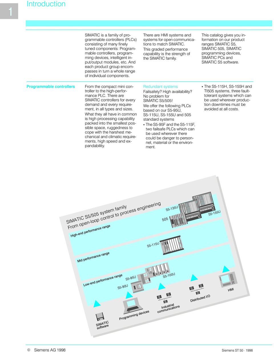
3 Programmable controllers Programming devices, software Industrial PC HMI Open communications Services

4 SIMATIC S5-90U SIMATIC S5-95U SIMATIC S5-90U SIMATIC S5-95U

5 SIMATIC S5-100U SIMATIC S5-100U

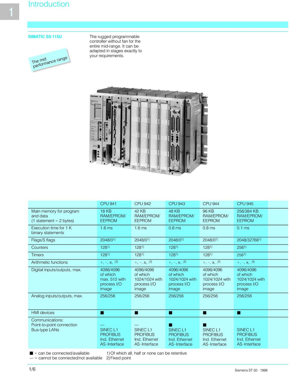
6 SIMATIC S5-115U
7 SIMATIC S5-135U SIMATIC S5-155U S5-135U S5-155U

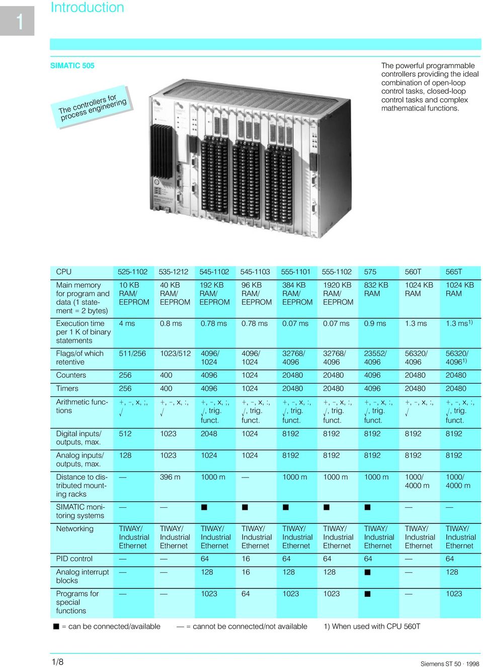
8 SIMATIC 505
9

10 S5-90U, S5-95U Application Programming, parameter assignment

11 S5-90U, S5-95U Mounting Mounting the S5-90U and S5-95U Expansion Expansion of the S5-90U and S5-95U

12 S5-90U, S5-95U Principle of operation Program memory Processor

13 S5-95F Application Typical fields of application of the S5-95F: Design Programming

14 S5-95F Safety rules Legal safety requirements S5-95F licenses DIN EN P1

15 S5-95F Safety rules EN DIN V 19250

16 S5-95F Mounting possibilities Expansion possibilities Safetyrelated expansion of the S5-95F Nonsafetyrelated expansion possibilities of the S5-95F Note:

17 S5-95F Safety-related modules and software components Module/software component Order No. Module/software component Order No. 6ES FB01 6ES FA12 6ES FB11 6ES MG11 6ES MA13 6ES FA11 or 6ES MA03 6ES BB00 6ES MA22 6ES BC00 6ES BF00 6ES CB00 6ES LA15 6ES FA12 6ES LA21 6ES NQ11 6ES LA41 6ES NR11 6ES FA11 6ES DH12 6ES FA11 Reaction-free, non-safety-related modules Module/software component Order No. 6ES MA11 6ES MA11 6ES MA13 6ES MA22 6ES MA21 6ES MA12 6ES MB11 6ES MA11 6ES MC11 6ES MB11 6ES MD11 6ES MA11 6ES ME11 6ES MA12 6ES MA12 6ES MB11 6ES MB12 6ES MC11 6ES MC12 6ES MA11 6ES MD12 6ES MC11 6ES MA12 6ES MB12 6ES MD11 6ES MA13 6ES MA11 6ES MA11 6ES MA11 6ES MA11 6ES MB11 6ES MA11 6ES MD11 6ES MA21 6ES MA11 6ES MB12 6ES MD11 6GK SA00 6ES MR12 6ES MA11 6ES MR11

18 S5-95F Principle of operation Synchronization Data exchange Interrupt processing Self-test

19 S5-95F Programming, parameter assignment Note! Communications possibilities

20 S5-95F Communications possibilities Operator control and process monitoring

21 S5-100U Application Design
22 S5-100U Design Programming Note
23 S5-100U Principle of operation Program memory Processor
24 S5-90U, S5-95U Design Technical specifications General
25 S5-90U, S5-95U Technical specifications
26 S5-90U, S5-95U Technical data Onboard digital inputs
27 S5-90U, S5-95U Technical specifications Ordering data S5-90U programmable controller 6ES MA01 Wall fastenings 6ES MB memory submodule Backup battery S5-90U/-95U system manual 35 mm DIN rail 6ES LA12 6ES LC11 6ES LC21 6ES AA00-0AA0 6ES MA12 6ES MA22 6ES MA32 6ES MA42 6ES MA52 6ES MA11 6ES MA21 6ES MA31 6ES MA41 IM 90 interface module Bus units, I/O modules Simulator STEP 5 package for mini controllers COM DB1 parameterization software 6ES ME11 6ES MK11 6ES MA03 6ES MA03-0KL1
28 S5-90U, S5-95U Ordering data Ordering data S5-95U programmable controller S5-95U programmable controller with PROFIBUS interface S5-95U programmable controller with 2nd serial interface S5-95U programmable controller with PROFIBUS-DP slave interface S5-95U programmable controller with PROFIBUS-DP master interface 375 memory submodule Backup battery S5-90U/-95U system manual Manual of the PROFIBUS interface of the S5-95U Manual of the 2nd serial interface of the S5-95U Manual of the PROFIBUS-DP interface of the S5-95U For Description of the S5-95U with PROFIBUS-DP master interface Manual of the ET 200 distributed I/O system 6ES MA03 6ES MB02 6ES MC01 6ES MD01 6ES ME01 6ES LA15 6ES LA21 6ES LA41 6ES LC11 6ES LC21 6ES LC31 6ES LC41 6ES LC61 6ES MA11 6ES MA 2 6ES MB 2 6ES MC 1 6ES MD 1 6ES ES 2 Power supply module 35 mm DIN rail Front connector Sub D connector Extractor tool Crimp contacts, Crimping tool for crimp contacts Bus units, I/O modules STEP 5 package for mini PLCs COM DB1 parameter assignment software 6ES MD11 6EW AB 6EW AB01 6ES MA13 6ES MA03 6ES MB11 6ES FB11 6ES AA11 6ES AA21 6ES MA11 6XX XX ES MA04 6ES MA04-0KL1 6ES MW
29 S5-95F Design Technical specifications =,
30 S5-95F Technical specifications Ordering data Ordering data S5-95F programmable controller Fiber optic connection cable 6ES FB01 6ES BB00 6ES BC00 6ES BF00 6ES CB00 35 mm DIN rail 6ES MA11 6ES MA21 6ES MA31 6ES MA memory submodule Backup battery S5-95F system manual Application Manual SIGUARD and SIMATIC S5-95F COM 95F parameterization software 6ES LA15 6ES LA21 6ES LA41 6ES MA11 6ES MF3 E20001-P285-A591-V1 E20001-P285-A591-V ES MF2 6ES MF2-0KL1 Front connector Extraction tool Crimp contacts, Crimping tool Sub D connector, 6ES MA13 6ES MA03 6ES FB11 6ES MA11 6XX XX ES AA
31 Press safety controller S5-95F/P Application Design, principle of operation Programming Ordering data Ordering data Press safety controller SIMAT- ICS5-95F/P 375 memory submodule Backup battery 6AT AA03-0XA0 6AT AA13-0XA0 6AT AA23-0XA0 6ES LA15 6ES MA11 Safety-related digital input Safety-related digital output Power supply modules, standard DIN rail Front connector Parameterization software COM 95F Documentation Brief description Description 6ES FA11 6ES FA11 6ES FB11 6ZB TV01-0BA1 6AT AB11-0AA0
32 S5-100U Application Design Programming Technical specifications CPU CPU 100 CPU 102 CPU 103
33 S5-100U Technical specifications CPU CPU 100 CPU 102 CPU 103 µ
34 S5-100U Technical specifications CPU CPU 100 CPU 102 CPU 103 Ordering data CPU CPU 100 CPU 102 CPU 103 S5-100U manual 6ES MA02 6ES MA02 6ES MA03 6ES UB13 6ES UB23 6ES UB33 6ES UB43 6ES UB memory submodule Backup battery COM DB1 parameter assignment software S5-100U reference guide 6ES LA15 6ES LA21 6ES LA41 6ES LC11 6ES LC21 6ES LC31 6ES LC41 6ES MA11 6ES MA
35 Digital input modules Application Design Technical specifications 6ES MA11 6ES MA12 6ES MA11 6ES MB11 6ES MC11 Number of inputs Input voltage 24 V DC 24 V DC 24 V DC 24/60 V DC 115 V UC
36 Digital input modules Technical specifications 6ES MD11 6ES MA11 6ES MC11 6ES MD11 6ES MA11 6ES FA11 Number of inputs Input voltage 230 V UC 24 V DC 115 V UC 230 V UC 5 V to 24 V DC 24 V DC Ordering data Digital input module 6ES MA11 6ES MA12 6ES MA11 6ES MB11 6ES MC11 6ES MD11 6ES MA11 6ES MC11 6ES MD11 6ES MA11 Failsafe digital input module Front connector 6ES FA11 6ES MA13 6ES MA03 6ES MB11 6ES FB11
37 Digital input modules
38 Digital output modules Application Design F L+ M L+ 2 M F L1 N FF 10A FF 10A 1 L+ N L+ F 2 M F M ]24V L+ 2 M L+ 2 M P M L+ M P M
39 Digital output modules Technical specifications 6ES MA12 6ES MA22 6ES MA11 6ES MB11 6ES MD11 Number of outputs Supply voltage 24 V DC 24 V DC 24 V DC 24/60 V DC 115/230 V DC Output current 0.5 A 2 A 0.5 A 0.5 A 1 A
40 Digital output modules Technical specifications 6ES MA11 6ES MD11 6ES MA11 6ES MR12 6ES MR11 6ES FA11 6ES FA12 Number of outputs Sply volt. Output current 24 V DC 1 A 115/230 V AC 0.5 A 5 to 24 V DC 0.1 A 24 V DC 24/60 V DC 24 V DC 2 A Continuous current 3 A 5 A
41 Digital output modules Ordering data Digital output module 6ES MA12 6ES MA22 6ES MA11 6ES MB11 6ES MD11 6ES MA11 6ES MD11 6ES MR12 6ES MR11 6ES MA11 Safety-related digital output module Front connector 1) Fuse 6ES FA11 6ES FA12 6ES MA13 6ES MA03 6ES MB11 6ES FB11 6ES MB21 6ES BC41
42 Digital input/output modules Application Design Technical specifications Digital inputs Digital outputs (continued) Digital outputs Supply voltage Output current Common data
43 Digital input/output modules OUT DIGITAL 16 X DC 24 V n + 1 n F F IN n + 1 n n n L+ L+ n + 1 n ,5 A M NC L+ NC ,5 A M 6 M ST a Ordering data Digital input/output module 6ES MA13 Front connector 6ES MA13 6ES MA03 6ES MB11 6ES FB11
44 Analog input modules Application Design Cu U Fe KO U U U U U U Dr. MU Dr. 4 Dr. MU MU + 4 Dr. MU U L Dr. 2 Dr. 2 Dr. 2 Dr. MU MU MU MU + M U U Ch. 0 Ch. 1 Ch. 2 Ch. 3 Ch. 0 Ch. 1 Ch. 2 Ch. 3 Ch. 0 Ch. 1 Ch. 1 Ch. 0 I C 0 I C 1
45 Analog input modules Technical specifications 6ES MA11 6ES MA21 6ES MB11 6ES Mc11 Nominal input ranges ± ± ± ± Number of inputs 1, 2 4 ± ± ± ± ± ± ± ± ± ±
46 Analog input modules Technical specifications 464-8MD ME MG MF MF MC11 ± ± ± ± ± ± ± ± ± ± ± ± ± ± Ordering data Analog input module ± ± ± ± ± ± 6ES MA11 6ES MA21 6ES MB11 6ES MC11 6ES MD11 6ES ME11 ± Failsafe analog input ± 6ES MF11 6ES MF21 6ES MC11 6ES MG11
47 Analog output modules Application Design
48 Analog output modules Technical specifications Analog output module 6ES MA12 6ES MB12 6ES MC12 6ES MD12 Nominal output range ± ± Number of outputs ± ± ± ± ± ± ± ± ± ± ± Ordering data Analog output module ± ± 6ES MA12 6ES MB12 6ES MC12 6ES MD12
49 General Application Fields of application Design Features
50 General Design Certifications Training and system manual for the S5-100U Ex I/Os
51 Ex digital input/output modules Application Ex Module No. of Intrinsically safe equipment channels which can be connected Design Status and fault indicators F F S 12 ST c 13 + S ST c
52 Ex digital input/output modules Technical specifications Ex digital input 6ES EA12 Ex digital output 6ES EA12 Ω Ω µ Ordering data Ex 437-8EA12 digital input module Ex 457-8EA12 digital output module 6ES EA12 6ES EA12 Barrier Training and system manual Ex S5-100U peripherals 6ES EA11 6ES EX12 6ES EX22 6ES EX32 Ex bus unit 6ES EA11
53 Ex analog input/output modules Application Ex module ± ± Number of channels Intrinsically-safe equipment which can be connected + S operating mode F 0 F 1 F 2 F 3 Ch Ch Ch Ch operating mode S F operating mode 3 Ch mA 7 Ch mA S operating mode F 0 F 1 7 Ic+ 3 M+ Ch 0 Ch M 8 Ic 9 Ic+ 5 M+ 6 M 10Ic operating mode F 4 Ch mA 8 Ch mA R>300? S 14
54 Ex analog input/output modules Technical specifications Ex analog input module 6ES EA11 6ES EE11 6ES EF11 Input range ± Ω Ω); ± Ω Ω Ω ± ± ± ± ± ± ± ± ± ± ± ± ± Ω Ω µ Ω
55 Ex analog input/output modules Technical specifications Ex analog output module 6ES EC11 Ω Ω ± ± Ordering data Ex 467-8EA11 analog input module ± Ex 467-8EE11 analog output module Ex 467-8EF11 analog input module ± 6ES EA11 6ES EE11 6ES EF11 Ex 477-8EC11 analog output module Ex bus unit Barrier Training and system manual Ex S5-100U peripherals 6ES EC11 6ES EA11 6ES EA11 6ES EX12 6ES EX22 6ES EX32
56 Overview Use of the IP modules IP 262 IP 263 IP 264 IP 265 IP 266 IP 267 S5-90U S5-95U S5-95F S5-100U with
57 IP 262 closed-loop control module Application Design Principle of operation Functions
58 IP 262 closed-loop control module Technical specifications Analog inputs Analog outputs Ω Ω ± ± Digital inputs ± ± Binary outputs Controller total cycle time Ordering data IP 262 closed-loop control module 6ES MA12 6ES MB12 Configuring package for IP 262 6ES AA11 6ES AA21 6ES AA31 6ES AA51 Subminiature-D connector 6ES AA31
59 IP 263 positioning module Application Design Principle of operation Technical specifications Processor User memory Encoders
60 IP 263 positioning module Technical specifications Digital input Digital output Supply voltage 24 V DC Ordering data IP 263 positioning module IP 263 manual 703 connecting cable 6ES MA13 6ES SK11 6ES SK21 6ES BF0 6ES CB0 6ES CC0 6ES CC5 6ES CD2 6ES BF0 6ES CB0 6ES CC0 6ES CC5 6ES CD connecting cable 6ES CB0 6ES CC0 6ES CD2 6ES CF0 6ES DB0 6ES CB0 6ES CC0 6ES CD2 6ES CF0 6ES DB0 6ES CC0 6ES CD2 6ES CF0 6ES DB0 6ES DC0 0 1 Sub D connector 6ES AA21
61 IP 264 electronic cam controller module Application Design µ µ µ Principle of operation Technical specifications Processor User memory Encoders
62 IP 264 electronic cam controller module Technical specifications Digital inputs Digital outputs Scan time µ µ Supply voltage Ordering data IP 264 electronic cam controller module IP 264 manual 6ES MA12 6ES SL11 6ES SL21 Connecting cables Sub D connector
63 IP 265 high-speed subcontrol module Application Design Features Principle of operation
64 IP 265 high-speed subcontrol module Principle of operation Programming Technical specifications Module Digital inputs µ µ
65 IP 265 high-speed subcontrol module Technical specifications Differential inputs Digital outputs Output circuit delay µ µ µ µ Expansion inputs/outputs Ordering data IP 265 high-speed subcontrol module Configuring package for IP 265 Standard function counter 6ES MA01 6ES AA11 6ES AA21 6ES AA31 6ES SH memory submodule Expansion cable Sub D connector Sub D connector 6ES LC21 6ES AC01 6ES AA11 6ES AB11
66 IP 266 positioning module Application Design Principle of operation
67 IP 266 positioning module Principle of operation Functions Operating modes Inputs/outputs Machine data Monitoring functions Technical specifications Incremental position decoding (pulse inputs) Binary inputs ± Binary outputs Controller output (analog output) ± ± ±
68 IP 266 positioning module Technical specifications (continued) Machine data (excerpt) µ Supply voltage ± ± Weight Ordering data IP 266 positioning module Configuring package for IP connecting cable 6ES MA11 6ES AA11 6ES AA21 6ES AA31 6ES BC50 6ES BF00 6ES CB00 6ES BC50 6ES BF00 6ES CB00 6ES CF connecting cable ± Sub D connector 6ES BF01 6ES CB01 6ES CC01 6ES CD21 6ES BF01 6ES CB01 6ES AA11 6ES AA21
69 IP 267 stepper motor controller Application Principle of operation Functions Technical specifications Digital inputs Output stage Ordering data IP 267 stepper motor controller IP 267 manual 6ES MA11 6ES SD11 6ES SD21 6ES SD31 6ES SD41 6ES SD connecting cable Sub D connector 6ES BF00 6ES CB00 6ES CB60 6ES AA11
70 385A and 385B counter modules Application Design 385A counter module 385B counter module Principle of operation 385A counter module 385A counter module PLC/ET Quantity Slots Technical specifications 6ES MA11 6ES MB11
71 385A and 385B counter modules Technical specifications 6ES MA11 6ES MB11 Inputs Outputs Ordering data 385A counter module 385 counter module 704 connecting cable 6ES MA11 6ES MB11 6ES BC50 6ES BF00 6ES CB connecting cable 705 connecting cable 6ES BC50 6ES BF00 6ES CB00 6ES CF00 6ES BF01 6ES CB01 6ES CC01 6ES CD21
72 380 timer module Application Technical specifications ± ± Ordering data 380 timer module 6ES MA11
73 461 comparator module Application Technical specifications Ω Ω ± ± Ordering data 461 comparator module 6ES MA11
74 788 simulation module Application Design Technical specifications Ordering data 788 simulator module 1) 6ES MA11
75
76 CP 521 SI communications processor Application Principle of operation Functions
77 CP 521 SI communications processor Technical specifications Ordering data CP 521 SI communications processor CP 521 SI manual 375 memory submodule 6ES MA22 6ES UD11 6ES UD21 6ES UD31 6ES LA15 6ES LA21 6ES LA41 6ES LC31 6ES LC41 SINEC L1 adapter MODBUS operating system slave submodule Backup battery Sub D connector 6ES AA11 6ES QA01 6ES MA11 6ES AA31
78 CP 521 BASIC communications processor Application Principle of operation Functions
79 CP 521 BASIC communications processor Technical specifications Ordering data CP 521 BASIC communications processor Manual COM 521 BASIC system program 6ES MB12 6ES UW11 6ES UW21 6ES UW memory submodule MODBUS operating system slave submodule 6ES LA15 6ES LA21 6ES LA41 6ES LC31 6ES LC41 6ES LD11 6ES LD21 6ES LD31 6ES QA01 Backup battery 6ES MA11 Sub D connector 6ES AA31
80 CP 541 communications processor Application Design SEND/RECEIVE (PLC/PLC) or FDLtype of communication PROFIBUS-DP type of communication
81 CP 541 communications processor Principle of operation Technical specifications Ordering data CP 541 communications processor connecting cable 6ES AA11 6ES BB00 6ES BC50 CP 541 manual 6ES DL11 6ES DL21 6ES DL31 6ES DL51
82 CP 2433 communications processor Application Design Principle of operation Technical specifications Ordering data CP GK SA00 Manual for AS interface 6GK SA01-0AA0 6GK SA01-0AA1 6GK SA01-0AA2 6GK SA01-0AA4
83 DIN rail Application Ordering data DIN rail 6ES MA11 6ES MA21 6ES MA31 6ES MA41 Ground terminal 6ES MA11 Bus units Application Design Technical specifications Bus unit 6ES5 700 Bus unit with interrupt 6ES MA11, -8FA11-8MB11-8MA22-8MB21 Bus unit 6ES5 700 Bus unit with interrupt 6ES MA11, -8FA11-8MB11-8MA22-8MB21 Ordering data Bus unit Bus unit with interrupt 6ES MA11 6ES FA11 6ES MA22 6ES MB11 6ES MB21 Crimp contacts Crimping tool Extraction tool Plug connection cover for bus unit 6XX XX ES MA11 6ES MA11
84 IM 315, IM 316 and IM 316F interface modules Application Technical specifications ± ± ± Ordering data IM 315 interface module IM 316 interface module 6ES MA11 6ES MA connecting cable 6ES AF00 6ES BC50 6ES BF00 6ES CB00 IM 316F interface module 6ES FA12
85 IM 90 interface module Application Technical specifications Ordering data IM 90 interface module 6ES ME11
86 PS 930 and PS 931 power supply modules, SIPAC power supply modules Application Technical specifications PS 930 PS 931 Stromversorgungsbaugruppen SIPAC Supply voltage 115/230 V AC 115/230 V AC SIPAC power supply module Stromversorgungsbaugruppen 380-1AB 380-4AB01 SIPAC 115/230 V AC Output current 1 A 2 A 4 A 115/230 V AC 10 A Ordering data PS 930 power supply module PS 931 power supply module 6ES MD11 6ES MD11 SIPAC power supply modules Fuse for 6EW AB 6EW AB01 6ES BC61
87
88 S5-115U Application
89 S5-115U Design Central configuration Distributed configuration Note General technical specifications
90 S5-115U Principle of operation Program memory Processor Programming
91 S5-115U Cyclic program execution Interrupt-driven program execution Time-controlled program execution Time interrupt-controlled program execution
92 S5-115U Communication SINEC L1 local area network Features PROFIBUS local area network Industrial Ethernet local area network
93 S5-115U Quality assurance procedures Availability Product planning Product development and production Product operation Safety Installation guidelines
94 S5-115H Application Design
95 S5-115H Design Normal fault tolerance Enhanced fault tolerance
96 S5-115H Design Maximum fault tolerance Mixed configuration
97 S5-115H Design Redundancy of IPs and CPs
98 S5-115H Principle of operation Data interchange and fault handling Synchronization
99 S5-115H Principle of operation Self-test Programming, parameter assignment Programming Parameter assignment
100 S5-115H Subracks for the S5-115H Interface modules for the S5-115H CPU for the S5-115H I/O modules for the S5-115H
101 S5-115F Application Requirement classes
102 S5-115F Design Safety-related areas Non-safety-related areas
103 S5-115F Principle of operation Comparison of inputs Comparison of outputs Comparison of further data
104 S5-115F Principle of operation Self-test during initialization Self-test in cyclic operation Programmming and parameter assignment Programming Note Parameter assignment
105 S5-115F Communication Features
106 S5-115F Communication Possible configurations Operator-control and process monitoring
107 S5-115F Subracks for the S5-115F Interfaces modules for the S5-115F CPU for the S5-115F I/O modules for the S5-115F Note
108 CPU 941, CPU 942, CPU 943 and CPU 944 central processing units for the S5-115U Application Design Functions Program execution Monitoring Software protection for RAM operation Scan time measurement
109 CPU 941, CPU 942, CPU 943 and CPU 944 central processing units for the S5-115U Functions Clock Integral function blocks Integral organization blocks µ Restart modes COM DB1 parameterization software For technical specifications Ordering data CPU 941 6ES UB , 3964R communications 6ES BB21 CPU 942 6ES UB11 protocol CPU 943 6ES UB memory submodules 6ES UB21 6ES LA15 CPU 944 6ES LA21 6ES UB11 6ES LA41 6ES UB21 6ES LA61 S5-115U manual 6ES LA71 6ES LC31 6ES LC41 6ES LD11 6ES LD21 6ES LD31 Standard function blocks 6ES UF13 6ES UF23 Programming software 6ES UF33 6ES UF43 6ES UF53 COM DB1 parameter assign- S5-115U quick reference guide 6ES LA11 6ES LA21 6ES LA31 6ES LA41 6ES LA51 ment software COM REG S5-115U parameter assignment software
110 CPU 945 central processing unit for the S5-115U Application Design Functions Program execution Monitoring Process I/O image transfer Changing the operating system Integral function blocks For technical specifications Ordering data CPU 945 S5-115U quick reference guide 6ES UA13 6ES UA23 6ES LB11 6ES LB21 6ES LB31 Interface modules Programming adapter Parameter assignment software 6ES LA12 6ES LA22 6ES LA42 6ES LA52 6ES LA62 6ES MC11 Memory card 6ES KG11 6ES KH21 6ES KJ11 Manual for the S5-115U with CPU 945 6ES UF11 6ES UF21 6ES UF31 6ES UF51
111 CPU 941, CPU 942, CPU 943, CPU 944 and CPU 945 central processing units for the S5-115U Technical specifications CPU CPU 945 CPU 944 CPU 943 CPU 942 CPU 941 µ µ µ µ µ µ µ µ µ µ µ µ µ µ µ µ µ µ µ µ µ µ µ µ µ µ µ µ µ µ µ µ µ µ µ µ µ µ µ µ
112 CPU 941, CPU 942, CPU 943, CPU 944 and CPU 945 central processing units for the S5-115U Technical specifications CPU CPU 945 CPU 944 CPU 943 CPU 942 CPU 941
113 CPU 942H central processing unit for the S5-115H Application Principle of operation Technical specifications Ordering data CPU 942H 6ES UH memory submodule COM 115H parameterization software Manual 6ES UH11 6ES UH21 6ES UH31 6ES UH41 6ES UH51
114 CPU 942F central processing unit for the S5-115F Application Principle of operation Technical specifications µ µ Ordering data CPU 942F 375 memory submodule 6ES UF15 COM 115F parameterization software S5-115F manual 6ES UF15 6ES UF25 6ES UF35 6ES UF55
115 Overview Digital input and output modules Digital input and output modules Input modules Output modules Input/output modules
116 Digital input modules Application Design Principle of operation Technical specifications Enable input Interrupt processing Note Digital input module Number of inputs Input voltage 24 V DC 24 V DC 24/48 V UC 48/60 V UC 24 V DC
117 Digital input modules Technical specifications Digital input module Digital input module Number of inputs Input voltage 115 V UC 115 V UC 115 V UC 230 V UC 230 V UC 230 V UC
118 Digital input modules Ordering data digital input module digital input module digital input module digital input module digital input module for NAMUR sensor digital input module digital input module 6ES LA11 6ES LA12 6ES LA11 6ES LA11 6ES UA12 6ES LA12 6ES LA11 6ES LB11 6ES LC digital input module 490 front connector 497 front connector Adapter casing 6ES LA11 6ES LB11 6ES LC11 6ES LB11 6ES LB21 6ES LA11 6ES LA21 6ES LC11 6ES UA12 6ES UB31
119 Digital input modules Connection diagrams
120 Digital input modules Connection diagrams
121 Digital output modules Application Design Principle of operation Short-circuit protection Parallel connection of outputs Note
122 Digital output modules Technical specifications Digital output module 6ES LA12 6ES LA11 6ES LA21 6ES LA11 6ES UA12 Number of outputs Supply voltage Output current V DC 0.5 A V DC 0.5 A V DC 0.5 A 16 24/48/60 V DC 0.5 A
123 Digital output modules Technical specifications Digital output module 6ES LA12 6ES LB11 6ES LA11 6ES LA11 6ES LB11 6ES LA11 Number of outputs Supply voltage V DC 8 24 V DC 16 48/115 V AC /230 V AC 8 115/230 V AC 32 5/12/24 V DC Output current 2 A 2 A 2 A/group 1 A 2 A 100 ma µ
124 Digital output modules Technical specifications Digital output module 6ES LA11 1) 6ES LB11 6ES LC11 Number of outputs Continuous current Supply voltage A 8 5 A 16 5 A Ordering data digital output module 6ES LA digital output module 6ES LA digital output module 6ES LA digital output module 6ES LA digital output module 6ES UA digital output module 6ES LA12 6ES LB digital output module 6ES LA digital output module 6ES LA11 6ES LB digital output module digital output module 490 front connector 6ES LA11 6ES LA11 6ES LB11 6ES LC11 6ES LB11 6ES LB21 6ES LA11 6ES LA21 6ES LC11
125 Digital output modules Connection diagrams
126 Digital output modules Connection diagrams
127 Digital input/output modules Application Design Principle of operation Interrupt processing Note Technical specifications Digital input/output module 6ES LA11 6ES LF11 6ES LF21 6ES LF31 6ES LA11 Number of inputs Input voltage 16, 24 V DC 16, 24 V DC 16, 24 V DC 8, 24 V DC V DC
128 Digital input/output modules Technical specifications Digital input/output module 6ES LA11 6ES LF11 6ES LF21 6ES LF31 6ES LA11 Number of outputs Supply voltage Output current 16, 24 V DC 0.5 A 16, 24 V DC 0.5 A 16, 24 V DC 0.5 A 8, 24 V DC 2.5 A V DC 1.5 A Ordering data digital input/output module 6ES LA11 6ES LF11 6ES LF21 6ES LF digital input/output module 490 front connector 6ES LA11 6ES LB21 6ES LA11 6ES LA21 6ES LC11
129 Digital input/output modules Connection diagrams
130 Analog input modules Application Design Principle of operation Note Technical specifications Analog input module 6ES LA13 6ES LA13 6ES U.12 Number of inputs Input ranges ± 50 mv; ± 500 mv; Pt 100; ± 1 V; ± 5 V; ± 10 V; V, V, ma ± 20 ma; ma ma Ω Ω; Ω; Ω Ω; Ω; Ω Ω; Ω Ω; Ω Ω
131 Analog input modules Technical specifications Analog input module 6ES LA13 6ES LA13 6ES U.12 ± ± ± ± ± ± ± ± ± ± ± ± ± ± ± ± ± ± ± ± ± ±
132 Analog input modules Technical specifications Analog input module Number of inputs Input ranges ± 6ES LA ma; ma; ± 20 ma V; V; V; V; V ± 1.25 V; ± 2.5 V; ± 5 V; ± 10 V Ω Ω µ ± ± ± ± ± ±
133 Analog input modules Ordering data analog input module analog input module 498 measuring range module ± ± ± ± ± ± analog input module 6ES LA13 6ES LA13 6ES AA11 6ES AA21 6ES AA61 6ES AA31 6ES AA41 6ES AA51 6ES AA71 6ES UA12 6ES UB analog input module 490 front connector 497 front connector K front connector Adapter casing 6ES LA11 6ES LB21 6ES LA11 6ES LA21 6ES LC11 6ES UA12 6ES UB31 6XX XX3 081 Connection diagrams
134 Analog input modules Connection diagrams
135 Analog output modules Application Design Principle of operation Note Technical specifications Analog output module 6ES L.13 Analog output module 6ES L.13 Number of outputs Output ranges 8 ±10 V; ma ±10 V V; ma Ω Ω ± ± ±
136 Analog output modules Ordering data 470-7LA analog output module ± 6ES LA LB analog output module ± 470-LC analog output module 6ES LB13 6ES LC front connector 6ES LB21 6ES LA11 6ES LA21 6ES LC11 Connection diagrams
137 Intelligent I/O modules Overview For further information, see Section 4.
138 Overview Overview Special tasks Supplementary equipment Simulation connectors Application Design Ordering data Simulation connectors 6ES SA11 6ES SA21
139
140 Communications modules and bus systems Overview Point-to-point connection Bus systems For further information, selection and ordering data, see Section 4.
141 CP 523 communications processor for the S5-115F Application Design Principle of operation Interfacing Message printout
142 CR 700-0LA subrack for S5-115U central controllers Application Design Ordering data CR 700-0LA subrack 6ES LA12
143 CR 700-0LB subrack for S5-115U central controllers Application Design Ordering data CR 700-0LB subrack 6ES LB11
144 CR subrack for S5-115U central controllers Application Design Ordering data CR subrack 6ES LA12
145 CR subrack for S5-115U central controllers Application Design Ordering data CR subrack 6ES LA12
146 CR subrack for S5-115U central controllers Application Design Ordering data CR subrack 6ES LA12
147 ER subrack for S5-115U expansion units Application Design Ordering data ER subrack 6ES LA11
148 ER subrack for S5-115U expansion units Application Design Ordering data ER subrack 6ES LA12
149 ER subrack for S5-115U expansion units Application Design Ordering data ER subrack 6ES LA12
150 ER subrack for S5-115U expansion units Application Design Ordering data ER subrack 6ES LA13
151 CR 700-0LB subrack for S5-115H central controllers Application Design Ordering data CR 700-0LB subrack 6ES LB11
152 CR subrack for S5-115H central controllers Application Design Ordering data CR subrack 6ES LA12
153 CR 700-2F subrack for S5-115H central controllers Application Design Ordering data CR 700-2F subrack 6ES LA22
154 CR subrack for S5-115H central controllers Application Design Ordering data CR subrack 6ES LA12
155 ER 701-3LH subrack for I/O modules in switched configuration with S5-115H Application Design Note on single-sided and two-channel configuration: Ordering data ER 701-3LH subrack 6ES LH11
156 CR 700-0LB subrack for S5-115F central controllers Application Design Ordering data CR 700-0LB subrack 6ES LB11
157 CR 700-2F subrack for S5-115F central controllers Application Design Ordering data CR 700-2F subrack 6ES LA22
158 ER subracks for S5-115F expansion units Application Design Ordering data ER subrack 6ES LA12
159 ER subrack for S5-115F expansion units Application Design Ordering data ER subrack 6ES LA12
160 ER subrack for S5-115F expansion units Application Design Ordering data ER subrack 6ES LA13
161 Fan subassembly Application Design Technical specifications For long subracks For short subracks Ordering data Fan subassembly Mounting accessories 6ES H11 6ES H 21 6ES G 11 Replacement fan 6ES NA11 Dust filter (filter mat) 6ES J 11 A B
162 PS 951 power supply modules for the S5-115U/H Application Design Technical specifications Power supply module 6ES LB21 6ES LD21 6ES NB21 6ES ND51 6ES ND41 Supply voltage Output current 230/120 V AC ± 3 A 3 A 230/120 V AC ± 7 A 15 A 24 V DC ± 3 A 3 A 24 V DC ± 7 A 15 A 24 V DC ± 7 A 15 A
163 PS 951 power supply modules for the S5-115U/H Ordering data PS 951 power supply module 6ES LB21 6ES LD21 6ES NB21 6ES ND51 6ES ND41 Backup battery, 6EW AA 6ES AE11
164 PS 951 power supply module for the S5-115F Application Design Technical specifications Supply voltage 24 V DC Output current Current consumption ± Ordering data PS 951 power supply module for S5-115F 6ES ND41 Backup battery 6ES AE11
165 Interface modules Overview IM 305 IM 306 IM 305 IM 306 IM 301 IM 310 IM 304 IM 314 IM 304 IM 314R IM 307 IM 317 IM 307 IM 308 IM IM IM 308-B IM 318-B/C
166 IM 305 and IM 306 interface modules; centralized configuration with S5-115U Application Design IM 305 interface module IM 306 interface module
167 IM 305 and IM 306 interface modules; centralized configuration with S5-115U Technical specifications IM 305 interface module IM 306 interface module Ordering data IM 305 interface module IM 306 interface module 6ES LA11 6ES LB11 6ES LA connecting cable 6ES AF00 6ES BB20 6ES BB50 6ES BC50
168 IM 304 and IM 314 interface modules; distributed configuration up to 600 m with S5-115U Application Design Connection of other programmable controllers
169 IM 304 and IM 314 interface modules; distributed configuration up to 600 m (1968 ft) with S5-115U Technical specifications Ordering data IM 304 interface module IM 314 interface module 6ES UB11 6ES UA11 Terminator Adapter casing 721 connecting cable 6ES AA11 6ES BB00 6ES BB60 6ES BC00 6ES BF00 6ES CB00 6ES CF00 6ES BC50 6ES BD20 6ES BJ 00 6ES CB20 6ES CB60 6ES CC00 6ES CC50 6ES CD20 6ES CE00 6ES CG30 6ES CJ 00 6ES DB00 6ES DF00
170
171 IM 308 and IM 318 interface modules; distributed configuration up to 3000 m with S5-115U Application Design Cables Ω Ω Ω
172 IM 308 and IM 318 interface modules; distributed configuration up to 3000 m with S5-115U Design Technical specifications Ordering data IM 308 interface module 376 memory submodule (EPROM) IM interface module 6ES UA12 6ES AA11 6ES UA11 IM interface module Adapter casing IM 308/IM 318 manual 6ES MA12 6ES DP11 6ES DP21 6ES DP31
173 IM 308-C interface module; PROFIBUS-DP interface for the S5-115U/H (up to S5-155U/H) Application Design Principle of operation Configuring Technical specifications Ordering data IM 308-C interface module 6ES UC11 Memory card 6ES FH21 6ES KK21
174 IM 304 and IM 324R interface modules, for interfacing the S5-115H central controllers Application Design Principle of operation Technical specifications Ordering data IM 304 interface module IM 324R interface module 6ES UB11 6ES UR11 Adapter casing 721 connecting cable
175 IM 304 and IM 314R interface modules, for distributed configuration of I/O modules at S5-115H Application Design Technical specifications Ordering data IM 304 interface module IM 314R interface module 6ES UB11 6ES UR11 Terminator for the IM 314R Adapter casing 721 connecting cable 6ES HA11
176 IM 304 and IM 324 interface modules; for interfacing the S5-115F central controllers Application Design Technical specifications Ordering data IM 304 interface module 6ES UB11 Adapter casing 721 connecting cable 6ES LB11 IM 324 interface module 6ES UA12
177 IM 306 interface module; for centralized configuration of I/O modules at S5-115F Application Design Note Principle of operation Ordering data IM 306 interface module 6ES LA connecting cable 6ES AF00 6ES BB20 6ES BB50 6ES BC50
178 IM 304 and IM 314 interface modules for distributed configuration of I/O modules at S5-115F Application Design Principle of operation Ordering data IM 304 interface module IM 314 interface module 6ES UB11 6ES UA11 Terminator for IM 314 interface module Adapter casing 721 connecting cable 6ES AA11
179 Front connector Application Design Technical specifications Front connector 6ES LB11 6ES LB21 6ES LA.. 6ES LC11 6ES Ordering data 490 front connector 6ES LB11 6ES LB21 K front connector 6XX bridge jumper 497 front connector 6ES LA11 6ES LA21 6ES LC11 6ES LA 11 Crimp contacts Crimping tool Extraction tool Labelling strips 6XX XX XX ES MA11 6ES LA11
180 Adapter casings Application Technical specifications Adapter casing 6ES LB11 6ES LD11 6ES LC11 Ordering data Adapter casing 6ES LB11 6ES LD11 6ES LC11
181 Text Display TD 390 Application Design Application Technical specifications Ordering data TD 390 text display 6ES UA11
182 S5-135U, S5-155U Application
183 S5-135U, S5-155U Application Design
184 S5-135U, S5-155U Design
185 S5-135U, S5-155U Design Central configuration Distributed configuration
186 S5-135U, S5-155U Design Housing Power supply chassis Backup battery
187 S5-135U, S5-155U Design Design and connection of the I/O modules
188 S5-135U, S5-155U Design Desing and connection of the I/O modules Principle of operation Program memory Processor
189 S5-135U, S5-155U Programming
190 S5-135U, S5-155U Communication SINEC L1 bus system Features PROFIBUS bus system Industrial Ethernet bus system
191 S5-135U, S5-155U Quality assurance procedures Product planning Product development and production Product operation Availability Safety Installation guidelines
192 S5-155H, S5-155H Lite Application
193 S5-155H, S5-155H Lite Design S5-155H S5-155H Lite
194 S5-155H, S5-155H Lite Design
195 S5-155H, S5-155H Lite Design
196 S5-155H, S5-155H Lite Design Selection criteria
197 S5-155H, S5-155H Lite Design
198 S5-155H, S5-155H Lite Principle of operation
199 S5-155H, S5-155H Lite Principle of operation
200 S5-155H, S5-155H Lite Programming, parameter assignment
201 CPU 928A Application Design
202 CPU 928A Restart modes Technical specifications Ordering data CPU 928 6ES UA21 Memory card with flash 6ES KG21 System manual, programming guide, manual
203 CPU 928B Application Design Restart modes
204 CPU 928B Design Restart modes Technical specifications Ordering data CPU 928 B System manual, programming guide, communications manual, instruction manual 6ES UB21 Memory card with flash EPROMs Interface module 6ES KG21 6ES AA12 6ES AA23 6ES AA43 6ES AA53 COM PP parameter assignment software 6ES AA62
205 CPU 948 Application Design Functions
206 CPU 948 Design Restart modes Technical specifications
207 CPU 948 Ordering data CPU 948 System manual, programming instructions, manual Memory card 6ES UA11 6ES UA21 6ES KH21 6ES KK21 6ES KL21 Interface module COM PP parameter assignment software 6ES AA12 6ES AA22 6ES AA43 6ES AA53 6ES AA62 Programming adapter 6ES MC11
208 923A and 923C coordinators Application Design Principle of operation Technical specifications Ordering data 923A coordinator 923C coordinator 6ES UA11 6ES UC connecting cable 6ES AK00 6ES BC50
209 CPU 948R/RL for S5-155H/S5-155H Lite Application Design Principle of operation Functions Programming
210 CPU 948R/RL for S5-155H/S5-155H Lite Technical specifications µ µ µ µ µ Ordering data CPU 948R CPU 948RL Memory card ZG 135U/155U subrack ZG 155H subrack 6ES UR12 6ES UR22 6ES UR51 6ES KH21 6ES KK21 6ES KL21 6ES UA12 6ES UA22 6ES UA32 6ES UA52 6ES UH31 S5-155H manual S5-135U/155U system manual 6ES SR11 6ES SR21 6ES SR31 6ES SH11 6ES SH21 6ES SH31 COM 155H parameterization software 6ES SR 3 6ES SR 3-0KL
211 Overview Digital input/output modules Input/output modules Digital input modules Application Design Principle of operation
212 Digital input modules Technical specifications Digital input module 6ES UA14 6ES UA14 6ES UA12 6ES UA12 1) Number of inputs Input voltage V DC V DC 16 24/48/60 V DC V DC Supply voltage
213 Digital input modules Technical specifications Digital input module 6ES UA12 6ES UA12 6ES UA12 1) 6ES UB12 1) Number of inputs Input voltage Supply voltage 32 TTL signals CMOS signals signals from NAMUR sensors 16 24/48/60 V AC /230 V AC 8 115/230 V AC
214 Digital input modules Ordering data digital input module digital input module digital input module digital input module digital input module digital input module 436-4UA digital input module 6ES UA14 6ES UA14 6ES UA12 6ES UA12 6ES UA12 6ES UA12 6ES UA UB digital input module 497 front connector 6ES UB12 6ES UA12 6ES UA224UA22 6ES UA42 6ES UB31 6ES UB12 6ES UB424UB42
215 Digital input modules
216 Digital output modules Application Design Principle of operation
217 Digital output modules Technical specifications Digital output module 6ES UA14 6ES UA14 6ES UA12 4) 6ES UA14 5) 6ES UA12 Number of outputs Supply voltage Output current 24 V DC 0.5 A 24 V DC 0.5 A 24 V DC 1) 2 A 24 V DC 2 A 24/48/60 V AC 2 A
218 Digital output modules Technical data Digital output module 6ES UA12 5) 6ES UB12 5) 6ES UA12 6) 6ES UA12 6ES UA12 Number of outputs Supply voltage 115/230 V AC 115/230 V AC 24/48/60 V DC 1) 24 V DC 24 V DC Output current 2 A 2 A 0.5 A
219 Digital output modules Technical specifications Digital output module 6ES UA12 1) 6ES UB12 1) 6ES UA12 2) 6ES UA12 6ES UA12 Ordering data digital output module 6ES UA UA digital output module 6ES UA digital output module digital output module digital output module digital output module 456-4UA digital output module 456-4UB digital output module digital output module 6ES UA14 6ES UA12 6ES UA14 6ES UA12 6ES UA12 6ES UB12 6ES UA UC digital output module 498 arc-suppression module 497 front connector 6ES UC11 6ES AB11 6ES UA12 6ES UA22 6ES UA42 6ES UB31 6ES UB12 6ES UB224UB22 6ES UB42
220 Digital output modules
221 Digital input/output module Application Design Technical specifications Number of inputs Input voltage V DC Supply voltage 24VDC Number of outputs 8 16 Output current 0.5 A
222 Digital input/output module Ordering data digital input/output module 6ES UA front connector 6ES UA12 6ES UA22 6ES UB31 6ES UB12
223 Overview Analog input/output modules ± ± ± ± ± ± ± ± ± Analog input modules Application Design
224 Analog input modules Design Technical specifications Analog input module 6ES UA13 6ES UA13 6ES U.12 Number of inputs Input ranges ± 12.5 mv ± 50 mv; ± 500 mv; Pt 100; ± 1 V; ± 5 V; ± 10 V; ± 20 ma; ma Ω Ω Ω; Ω Ω; Ω; V, V, ma ma Ω Ω; Ω Ω Ω Ω; Ω; ± ± ± ± ±
225 Analog input modules Technical specifications Analog input module 6ES UA13 6ES UA13 2) 6ES U.12 ± ± ± ± ± ± ± ± ± ± ± ± ± ± ± ± ± ± ± Analog input module Number of inputs Input ranges 6ES LA ma; mA; ± 20 ma V; V; V; V; V ± 1.25 V; ± 2.5 V; ± 5 V; ± 10 V; Ω Ω µ ± ±
226 Analog input modules Technical specifications Analog input module ± 6ES LA11 ± ± ± ± Ordering data analog input module analog input module 498 measuring range module ± ± ± ± ± ± ± 6ES UA13 6ES UA13 6ES AA11 6ES AA21 6ES AA61 6ES AA31 6ES AA41 6ES AA51 6ES AA analog input module analog input module 497 front connector Front connector 6ES UA12 6ES UB12 6ES LA11 6ES UA124UA12 6ES UA22 6ES UB31 6ES UB12 6XX XX3 081
227
228 Analog output modules Application Design Principle of operation Technical specifications Number of outputs 8 Output ranges ± 10 V; ma ± 10 V V; mA Ω Ω Supply voltage ± ± ±
229 Analog output modules Ordering data 470-4UA analog output module ± 470-4UB analog output module ± 470-4UC analog output module 6ES UA13 6ES UB13 6ES UC front connector 6ES UA12 6ES UA22 6ES UB31 6ES UB12
230 Overview Application Signal preprocessing
231 IP 240 counter, position decoder and positioning module Application Design Principle of operation
232 IP 240 counter, position decoder and positioning module Principle of operation Technical specifications Pulse inputs Binary inputs Binary outputs Ordering data IP 240 counter, position decoder and positioning module Configuring package for IP 240 6ES AA21 6ES AA11 6ES AA21 6ES AA31 6ES AA connecting cables Sub D connector 6ES BF01 6ES CB01 6ES CC01 6ES CD21 6ES AA21
233 IP 242A and IP 242B counter modules Application Design Features Principle of operation Technical specifications Counter module IP 242A IP 242B
234 IP 242A and IP 242B counter modules Technical specifications Counter module IP 242A IP 242B µ Ordering data IP 242A counter module Upgrade kit IP 242B counter module Configuring package for IP 242A/B 6ES AA32 6ES AA41 6ES AB11 6ES AB21 6ES AB31 6ES AB51 Connector Converter 705 connecting cable 6ES AB11 6ES AU11 6ES BF00 6ES CB00 6ES CC00
235 IP analog module Application Design Principle of operation Technical specifications A/D converter, 12 bit 1 Ω µ D/A converter, 12 bit 2 Ω µ
236 IP analog module Technical specifications D/A converter, 8 bit Analog value matching Difference amplifier Comparator Binary inputs 1 Ω µ 4 Ω 2 Ω Ω 2 Ω 8 Binary outputs General data 8 µα Ordering data IP analog module IP manual 6ES AA13 6ES KF11 6ES KF21 6ES KF31 Front connector K Standard-function blocks 6XX XX ES MA01
237 IP 244 temperature control module Application Design Inputs Outputs Principle of operation Controller characteristics
238 IP 244 temperature control module Principle of operation Controller self-optimization
239 IP 244 temperature control module Principle of operation Actual-value processing Setpoint processing Analog output Heating current monitoring Note Technical specifications Analog inputs Ω Ω Ω
240 IP 244 temperature control module Technical specifications Analog inputs Binary input Controller Outputs General specifications µ Ordering data IP 244 temperature control module Configuring package for IP 244 6ES AB31 6ES AA11 6ES AA21 6ES AA31 6ES AA connecting cables 6ES BC50 6ES BD20 6ES BF00 6ES CB00 6ES CD20 6ES BC50 6ES BF00 6ES CB00 6ES CD20 6ES CF00
241 IP 246I and IP 246A positioning modules Application Design Principle of operation
242 IP 246I and IP 246A positioning modules Principle of operation Functions IP 246I IP 246A
243 IP 246I and IP 246A positioning modules Technical specifications Position detection, incremental Controller output Machine data Position detection, absolute Supply voltages Binary inputs/outputs
244 IP 246I and IP 246A positioning modules Ordering data IP 246I positioning module IP 246A positioning module Configuring package for IP 246I/A Sub D connector 706 connecting cable 6ES UA31 6ES UB11 6ES AA11 6ES AA21 6ES AA31 6ES AB21 6ES AA21 6ES AA11 6ES BF00 6ES CB00 6ES CC00 6ES CD20 6ES BF00 6ES CB00 6ES CC00 6ES CD connecting cable connecting cable 6ES BF00 6ES CB00 6ES CC00 6ES CD20 6ES BF00 6ES CB00 6ES CC00 6ES CD20 6ES BF00 6ES CB00 6ES CC00 6ES BB00 6ES BF00 6ES CB00 6ES CC00 6ES B F01 6ES CB01 6ES CC01 6ES CD21
245 IP 247 positioning module Application Principle of operation
246 IP 247 positioning module Technical specifications Signal to the power section Binary inputs/outputs Machine data Supply voltages Ordering data IP 247 positioning module Configuring package for IP 247 Sub D connector 6ES UA31 6ES AA11 6ES AA21 6ES AA31 6ES AA11 6ES AA connecting cable 6ES BB60 6ES B F00 6ES CB00 6ES CC00 6ES CF00 6ES BC00 6ES BF00 6ES CB00 6ES CC00 6ES CF00
247 IP 281 counter module Application Design Features Principle of operation
248 IP 281 counter module Technical specifications Ordering data IP 281 counter module Plug-in submodule IP 281 manual 703 connecting cable 6ES UA12 6ES UP12 6ES UB12 6ES KP11 6ES KP21 6ES KP31 6ES KP51 6ES BF0 6ES CB0 6ES CC0 6ES CC5 6ES CD2 6ES BF0 6ES CB0 6ES CC0 6ES CC5 6ES CD2 703 connecting cable Sub D connector 6ES CB0 6ES CC0 6ES CD2 6ES CF0 6ES DB0 6ES CB0 6ES CC0 6ES CD2 6ES CF0 6ES DB ES AA21 0 1
249 WegerfassungsbaugruppeWF 705 Anwendungsbereich Aufbau Arbeitsweise Technische Daten
250 WegerfassungsbaugruppeWF 705 Bestelldaten Wegerfassungsbaugruppe WF 705 Istwertverteiler Standard-Software WF 705 Beschreibung WF 705 6FM AA00 6FM AA00 6FM UA30-1AA0 6FM UA30-1AA5 6ZB AA01-0BA5 6ZB AA02-0BA5 Steckleitung 790/590 6FM GA00 6FM GB00 6FM GC00 6FM GD00 6FM GZ00 6FM HA00 6FM HB00 6FM HZ00 6FM EA00 6FM EB00 6FM EC00 6FM ED00 6FM EE00 6FM EF00 6FM EG00 6FM EH00 6FM EZ00
251 WegerfassungsbaugruppeWF 706 C Anwendungsbereich Aufbau Arbeitsweise
252 WegerfassungsbaugruppeWF 706 C Gesteuerte Positonierung mit IP 240 oder WF 706 C IP 240 WF 706 ± Technische Daten
253 WegerfassungsbaugruppeWF 706 C Technische Daten Bestelldaten Positionierbaugruppe WF 706 C Analogmodul Beschreibung WF 706 6FM AA20 6FM AB20 6FM AA00 6ZB KR01-0BA7 Steckleitung 790 6FM BB00 6FM BC00 6FM BD00 6FM BZ00 6FM CA00 6FM CB00 6FM CC00 6FM CD00 6FM CZ00 6FM FA00 6FM FB00 6FM FC00 6FM FD00 6FM FZ00
254 Nockensteuerwerk WF 707 Anwendungsbereich Aufbau Arbeitsweise
255 Nockensteuerwerk WF 707 Gesteuerte Positonierung mit IP 241 und WF 707 IP 241 WF 707 Technische Daten
256 Nockensteuerwerk WF 707 Technische Daten Bestelldaten Nockensteuerwerk WF 707 Steckleitung 790 6FM AA10 6FM JS00 6FM JA00 Wegmeßgeber Beschreibung WF 707 6FX CB00 6FX CC00 6FX CC50 6ZB5440-0ST01-0BA3
257 PositionierbaugruppenWF 721/WF 723 A/WF 723 B/WF 723 C Anwendungsbereich Aufbau
258 PositionierbaugruppenWF 721/WF 723 A/WF 723 B/WF 723 C Arbeitsweise WF 721 WF 723 A WF 723 B WF 723 C Geregelte Positionierung mit IP 246, WF 721 oder WF 723 A IP 246 WF 721 WF 723 A ± ± ±
259 PositionierbaugruppenWF 721/WF 723 A/WF 723 B/WF 723 C Programmierung WF 721 WF 723 A WF 723 B WF 723 C WF 721 WF 723 A WF 723 B WF 723 C
260 PositionierbaugruppenWF 721/WF 723 A/WF 723 B/WF 723 C Programmierung Technische Daten WF 721 WF 723 A WF 723 B WF 723 C ± ± ± ±
261 PositionierbaugruppenWF 721/WF 723 A/WF 723 B/WF 723 C Technische Daten WF 721 WF 723 A WF 723 B WF 723 C ± ± ± ± ±
262 PositionierbaugruppenWF 721/WF 723 A/WF 723 B/WF 723 C Technische Daten WF 721 WF 723 A WF 723 B WF 723 C Bestelldaten Positionierbaugruppe WF 721 Positionierbaugruppe WF723A Firmware-Hochrüstsatz WF 721 Firmware-Hochrüstsatz WF 723 A Positionierbaugruppe WF 723 B Firmware-Hochrüstsatz WF 723 B Positionierbaugruppe WF 723 C Wegmeßgeber, Standard A Standard B-470 Standard-B-GRACIS ULB Standard B-GRACIS OLB Standard-B-OP 25 Software-Pakete Software COM 723 PC-Steuern 6FM AA20 6FM AA10 6FM AA00 6FM AA00 6FM BA00 6FM BA00 6FM CA00 6FX CB00 6FX CC00 6FX CC50 6FM UA31-1AA0 6FM AA31-1AA0 6FM UD31-1MA0 6FM UC31-1AA0 6FM AA30-1MA0 6FM UA31-1AA0 6FM UB30-1MA0 Dokumentation Steckleitung 790 6ZB PW01-0BA5 6ZB VK01-0BA2 6ZB VK02-0BA2 6ZB RS01-2AA6 6ZB RS02-2AA5 6ZB SB01-0BA1 6ZB SC01-0BA1 6ZB VM01-0BA1 6ZB VM02-0BA1 6ZB SJ01-2AA2 6ZB SJ02-2AA2 6ZB VS01-0BA0 6ZB VS02-0BA0 6ZB VP01-0BA2 6ZB VP02-0BA2 6ZB VY01-0BA1 6ZB VY02-0BA1 6ZB WA01-2AA2 6FM BA00 6FM BB01 6FM BC00 6FM BZ00 6FM CA00 6FM CB00 6FM CC00 6FM CD00
263 Overview Overview Special functions Supplementary devices CP 516 memory submodule Application Design Principle of operation Technical specifications Ordering data CP 516 memory submodule Standard function blocks CP 516 manual 6ES UA11 6ES EB11 6ES EB21 6ES EB31 Memory card Lithium backup battery 6ES AH21 6ES AJ21 6ES AK21 6ES FH21 6ES FK21 6ES FL21 6ES FM21 6ES AE11
264 CP 581; the integral PC in the SIMATIC Application Design CP 581 basis board Mass storage module Slot module CP 581 system software
265 CP 581, the integral PC in the SIMATIC Design Operating system Principle of operation Functions Process data acquisition S5 drive emulation
266 CP 581, the integral PC in the SIMATIC Functions Mass storage functions Command interpreter Programming Additional functions Technical specifications Basic board Mass storage module Slot module
267 CP 581, the integral PC in the SIMATIC Ordering data CP 581 basic board 6ES ED13 RGB/VGA adapter 6ES AV01 Memory expansion Y adapter Extension for keyboard/mouse RTI connecting cable PG keyboard 6ES AM00-0AA0 6ES AN00-0AA0 6ES AP00-0AA0 6ES AQ00-0AA0 6ES BM10-0AA0 6ES AS01 6ES AT01 6ES AA12 6ES CB00 6ES CC00 6ES CC50 6ES CD20 6ES CE00 6ES CF00 6ES CG30 6ES C J00 6ES DB00 6ES DC00 6ES CA00 0AX0 Connecting cables for monitors Mass storage module Slot module CP 581 system software Operating system MS-DOS V Upgrade CP 581 manual CP 581 DDE server 6ES BD20 6ES BF00 6ES CB00 6ES LA11 6ES RA12 6ES MD01 6ES MD01-0KL1 6ES BS22 6ES BS32 6ES AT11 6ES AT21 6ES AT31 6ES DD11 6ES DD11-0KL1 6ES DD21 6ES DD21-0KL1
268 Simulation modules Application Design 788-7LA simulation module 788-7LB simulation module 788-7LC simulation module Ordering data 788-7LA simulation module 788-7LB simulation module 788-7LC simulation module 6ES LA11 6ES LB11 6ES LC11 Manual Connecting cables 6ES EA11 6ES EA21
269
270 Picture evaluation systems Introduction SIMATIC VIDEOMAT picture evaluation system Application Features
271 SIMATIC VIDEOMAT picture evaluation system (continued) Design Principle of operation Technical specifications
272 SIMATIC VIDEOMAT picture evaluation system (continued) Ordering data SIMATIC VIDEOMAT for monochrome picture evaluation SIMATIC VIDEOMAT for color picture evaluation SIMATIC VIDEOMAT manual 6GF BC01 6GF BE01 6GF CC01 6GF CA01 6GF CA02 CCD camera with C mount Single-chip-RGB color camera Lenses for above cameras Lighting equipment 14 color monitor Keyboard Mouse 6GF AA 6GF BA 6GF MA C7951-Z727-K3 6ES AA00-0XA0 Connecting cables for VIDEOMAT 6GF AG 6GF BD 6GF BE
273 Communications processors and bus systems Overview Point-to-point connection Bus interfacing Communication Communication SINEC L1 AS interface PROFIBUS Industrial Ethernet
274 CP 523 communications processor Application Design Interface Principle of operation Interfacing
275 CP 523 communications processor Principle of operation Message printout Programming Ordering data CP 523 communications processor 375 memory submodule Program examples 6ES UA11 6ES LA15 6ES LA21 6ES LA41 6ES LC31 6ES LC41 6ES UE11 Manual Connecting cables 6ES DD11 6ES DD21 6ES DD31 6ES DD41 6ES DD51
276 CP 524 communications processor Application Design Interfaces
277 CP 524 communications processor Principle of operation Interfacing Listing Programming Ordering data CP 524 communications processor 752 interface submodule 373 memory submodule COM 525 parameter assignment software 6ES UA15 6ES AA12 6ES AA22 6ES AA43 6ES AA41 6ES AA61 6ES AA81 Special drivers Manual Connecting cables 6ES DB11 6ES DB21 6ES DB31
278 CP 544, CP 544B communications processors Application Design Interfaces
279 CP 544, CP 544B communications processors Principle of operation Programming Technical specifications Communications processors CP 523 CP 524 CP 544 and CP 544B
280 CP 523, CP 524, CP 544 and CP 544B communications processors Technical specifications for CP 523, CP 524, CP 544 and CP 544B Communications processors CP 523 CP 524 CP 544 und CP 544B Ordering data CP 544 communications processor CP 544B communications processor 752 interface submodule Memory card COM PP parameterization software CP 544 adapter cable Special driver for CP 544B CP 544/CP 544B manual 6ES UA11 6ES UB11 6ES AA12 6ES AA22 6ES AA43 6ES KH21 6ES AH21 6ES AG00 6ES DB11 6ES DB21 6ES DB31 725, 726, 734 connecting cables 6ES BD20 6ES B F00 6ES CB00 6ES CF00 6ES DC00 6ES BC00 6ES BD20 6ES BF00 6ES CB00 6ES CB60 6ES B F00 6ES CB00 6ES CF00 6ES DC00 6ES BD20 6ES B F00 6ES CB00 6ES CF00 6ES DC00 6ES BC00 6ES BD20 6ES BF00 6ES CB00 6ES CC00
281 CP 523, CP 524, CP 544 and CP 544B communications processors Ordering data 725, 726 and 734 connecting cables 6ES BD20 6ES B F00 6ES CB00 6ES C F00 6ES DC00 6ES BC00 6ES BD20 6ES B F00 6ES CB00 6ES CB60 6ES BD20 6ES B F00 6ES CB00 6ES C F00 6ES DC00 6ES BF00 6ES CB00 6ES CC50
282 CP 2430 communications processor; AS-Interface Application Design Principle of operation User interface
283 CP 2430 communications processor; AS-Interface Technical specifications Ordering data CP GK SA10 Manual for AS-Interface 6GK SA01-0AA0 6GK SA01-0AA1 6GK SA01-0AA2 6GK SA01-0AA4
284 CP 5431 FMS/DP communications processor; PROFIBUS Application Design Principle of operation
285 CP 5431 FMS/DP communications processor; PROFIBUS Technical specifications PROFIBUS overview PROFIBUS electrical 5431 FMS/DP comm. processor PROFIBUS optical Ordering data CP 5431 FMS/DP communications processor COM 5431 FMS/DP parameter asgmt software CP 5431 FMS/DP manual 376 memory submodule 377 memory submodule RS 485 bus terminal for PROFIBUS Bus cables for PROFIBUS Bus cable 2-wire, shielded Bus cable, halogen free 6GK AA01 6GK AB01-0AA0 6GK AB01-0AA1 6GK AB01-0AA2 6ES AA11 6ES AA21 6ES AA31 6ES AA11 6ES AA21 6ES AA32 6GK AA00 6GK AB00 6XV AH10 6XV CH10 Bus cable for PROFIBUS (ctd. Bus cable with PE coating Bus cable (buried) Trailing cable Bus cable for festoon mounting Bus cable for PROFIBUS-PA FIBER OPTIC CABLE standard cable, splittable FLEXIBLE FIBER OPTIC CABLE trailing cable, splittable BFOC connector; 6XV BH10 6XV AH10 6XV BH10 6XV AH10 6XV AH10 6XV BH10 6GK DA00-0AA0
286 CP 1430 TF/CP 1430 TCP/CP 1473 MAP communications processors; Industrial Ethernet Application CP 1430 TF/1430 TCP communications processor CP 1473 MAP communications processor Design CP 1430 TF/1430 TCP communications processor CP 1473 MAP communications processor Principle of operation Programming
287 CP 1430 TF/CP 1430 TCP/CP 1473 MAP communications processors; Industrial Ethernet Technical specifications Industrial Ethernet electrical Transceiver Repeater Industrial Ethernet fiber optic µ SSV 104 fan-out unit CP 1430 TF/CP 1430 TCP/ CP 1473 MAP communications processors
288 CP 1430 TF/CP 1473 MAP communications processors; Industrial Ethernet Ordering data Communications processor CP 1430 TF Basic CP 1430 TF Extended COM 1430 TF parameter assignment software CP 1430 TF/COM 1430 TF manual CP 1430 TCP communications processor COM 1430 TCP parameter assignment software CP 1430 TCP/COM 1430 TCP manual CP 1473 MAP communications processor COM 1473 TCP parameter assignment software CP 1473 MAP manual Connecting cable PG 7xx/CP 1473 CP-PLC cable 376 memory submodule Memory card Bus transceiver for Industrial Ethernet 6GK TA02 6GK TB01 6GK TA43-0AA0 6GK TA43-0AA1 6GK TA43-0AA2 6GK TA43-0AA4 2XV AU00 2XV AU03 2XV AU02 6GK MA00 6GK MA73-0AA0 6GK MA73-0AA1 6XV CH25 6XV FE60 6ES AA11 6ES AA21 6ES AA31 6ES KH21 6ES AH21 6GK AA00-0AA0 Bus transceiver w/ 2 interfaces 6GK AA00-0AC0 for Industrial Ethernet SIBUKO transceiver package 2 6GK AB00 for Industrial Ethernet Terminating resistors 6ES AA11 Coaxial connector 6ES AA11 Repeater 6ES AA12 SSV 104 fan-out unit 6GK AA connecting cable 6ES BD bus cable connecting cable 6ES CB00 6ES CB50 6ES CC00 6ES CD20 6ES CF00 6ES AA11 6ES AK00 6ES BC50
289 135U/155U central controller Application Design S5-135U, S5-155U S5-155H Power supply chassis
290 135U/155U central controller Design
291 135U/155U central controller Principle of operation Multiprocessor operation Ordering data 135U/155U central controller 6ES UA12 6ES UA22 6ES UA32 6ES UA52 Backup battery S5-135U/155U system manual Additional manuals Replaceable fan Accessories, spare parts 6EW AA 6ES NB41 135U central controller 6ES UA42
292 155H central controller Application Design Ordering data 155H central controller 6ES UH31 S5-155H manual Backup battery 6ES BA00 Other manuals Accessories, parts
293 183U expansion unit Application Design Possible configurations Ordering data 183U expansion unit 6ES UA13 6ES UA22 S5-135U/155U system manual Additional manuals Accessories, spare parts
294 184U expansion unit Application Design Possible configurations Ordering data 184U expansion unit 6ES UA11 6ES UA21 S5-135U/155U system manual Additional manuals Accessories, spare parts
295 EG 185U expansion unit Application Design
296 185U expansion unit Design Ordering data 185U expansion unit 6ES UA13 6ES UA33 6ES UA23 6ES UA43 S5-135U/155U system manual Additional manuals Accessories, spare parts Backup battery 6EW AA
297 187U expansion unit Application Design Ordering data 187U expansion unit 6ES UA11 Additional manuals S5-135U/155U system manual Accessories, spare parts
298 Power supply chassis Technical specifications Power supply 6ES5 955 chassis Input voltage 230 V/120 V AC 24 V DC 24 V DC 24 V DC DC 24 V Number of outputs Output voltage ± ± ± ± 15 V submodule 6ES AA12 (for power supply only 6ES NA12) Output voltage ±
299 SITOP load power supplies Application
300 SITOP load power supplies Technical specifications Equipment series basic line special line universal line ± ± ± ± Ordering data Power supply SITOP power basic line 6EP SL11 6EP SL11 6EP SL11 6EP SL11 6EP SL11 Power supply SITOP power universal line 6EP SH11 6EP SH21 6EP SH01 6EP SH01 Power supply SITOP power special line 6EP AL11 6EP AL11 6EP AL01
301 Overview Overview IM IM IM IM IM IM 306 IM IM IM IM IM IM IM IM IM 310 IM IM 304 IM 314 IM 314R IM 308 IM IM IM 307 IM 317 IM 307
302 IM 300 and IM 312 interface modules; centralized configuration Application Design Technical specifications Ordering data IM 300 interface module IM 306 interface module 705 connecting cable 6ES CA11 6ES AB11 6ES LB11 6ES LA11 6ES AF00 6ES BB20 6ES BB50 6ES BC50 IM 312 interface module Terminator for the IM interface module 6ES CA12 6ES CA22 6ES AB12 6ES AB32 6ES AB11
303 IM 300 and IM 312 interface modules; centralized configuration
304 IM 301 and IM 310 interface modules; distributed configuration up to 200 m (656 ft) Application Design Technical specifications Ordering data IM 301 interface module Terminator for the IM 301 IM 310 interface module Terminator for the IM 310 6ES CA12 6ES AB13 6ES AA11 6ES AB11 6ES AB11 6ES AA connecting cable 6ES BB00 6ES BB60 6ES BC00 6ES BC50 6ES BD20 6ES BF00 6ES BJ00 6ES CB00 6ES CB20 6ES CB60 6ES CC00 6ES CC50 6ES CD20 6ES CE00 6ES CF00 6ES CG30 6ES CJ00 6ES DB00 6ES DF00
305 IM 301 and IM 310 interface modules; distributed configuration up to 200 m (656 ft)
306 IM 304 and IM 314 interface modules; distributed configuration up to 600 m (1969 ft) Application Design Technical specifications Ordering data IM 304 interface module IM 314 interface module Terminator for the IM 314 6ES UB11 6ES UA11 6ES AA connecting cable
307 IM 304 and IM 314 interface modules; distributed configuration up to 600 m (1969 ft)
308 IM 308 and IM 318 interface modules; distributed configuration up to 3000 m (9900 ft) and ET 100U connection Application Design Ω Ω Ω. Technical specifications
309 IM 308 and IM 318 interface modules; distributed configuration up to 3000 m (9900 ft) and connection of the ET 100U Ordering data IM 308 interface module IM interface module 6ES UA12 6ES MA12 IM interface module Manual Distributed I/Os, IM 308-3U/318-3U 6ES UA11 6ES DP11 6ES DP21 6ES DP31
310 IM 308-C interface module; PROFIBUS-DP interface for S5-115U/H up to S5-155U/H Application Design Principle of operation Configuration Technical specifications Ordering data IM 308-C interface module 6ES UC11 Memory card 6ES KH21 6ES KK21
311 IM 304 and IM 324R interface modules for interfacing the S5-155H central controllers Application Design Principle of operation Technical specifications Ordering data IM 304 interface module IM 324R interface module 6ES UB11 6ES UR connecting cable
312 IM 304 and IM 314R interface modules for switched configuration at S5-155H Application Design
313 IM 304 and IM 314R interface modules for switched configuration at S5-155H Principle of operation Technical specifications Ordering data IM 304 interface module IM 314R interface module Terminator for IM 314R 6ES UB11 6ES UR11 6ES HA connecting cable
314 Front connectors Application Design Technical specifications Front connector 6ES Ordering data 497-4UA front connector 6ES UA12 6ES UA22 6ES UA UB front connector 6ES UB31 6ES UB12 6ES UB22 6ES UB42
315 Front connectors Ordering data Front connector K for 6ES LED extension 6XX XX ES UL21 6ES UL11 Crimp contacts Crimping tool Extraction tool 6XX XX ES UC11 Manuals, further accessories Ordering data S5-135U/155U system manual 6ES SH11 6ES SH21 6ES SH31 6ES SH41 6ES SH51 Manuals S5-135U/155U pocket guide 6ES UA Programming instructions Communications manual for CPU 928B S5-135U/155U manual for CPU 922 CPU 928 CPU 928B CPU 948 6ES PR1 6ES PR1 6ES PR1 6ES PR1 6ES CN2 6ES UL3 6ES UL4 6ES UL4 6ES UM S5-155H manual Power supply chassis Fan chassis for EG 184U Spare fan 6ES SR11 6ES SR21 6ES SR31 6ES LC41 6ES LF41 6ES NC41 6ES NF41 6ES NA12 6ES LA11 6ES NA11 6ES NB41
316 Manuals, further accessories Ordering data Accessories for ZG 135U/155U, EG 183U to EG 187U Accessories for ZG 135U/155U, EG 183U to EG 187U Spare fan (set of 2) Backup battery Rechargeable battery 6ES LB21 6ES NB11 6EW AA 6ES DA11 6ES NC11 Dust filter (set of 10) Dummy front plates 15 V module 6ES EA11 6XF KB00 6XF KB00 6ES AA12 Baffle plate Dust filter holder Dust filter (set of 10) Dust filter holder 6ES DA11 6ES FA41 6ES EA41 6ES FA11 Accessories for ZG 155H Power supply Fan subassembly Replacement fan Dust filter (10 items) Backup battery 6ES NC11 6ES TA01-0XA0 6ES TA00-6AA0 6ES TA00-7AA0 6ES BA00
317
318 Application Design Compactness Intelligent I/O modules Distributed control
319 Design Redundant systems
320 Programming General technical specifications Safety and reliability Insulation group Temperature range Humidity Mechanical shock test Ordering data TI525 to TI565 Mounting racks for TI505 Power supply units CPUs TI525 TI535 TI545 PPX: PPX: PPX: PPX: PPX: PPX: A PPX: PPX: PPX: PPX: CPUs Firmware upgrade kit TI555 TI560T TI565T PPX: PPX: PPX: PPX: PPX:560T1KM-1101 PPX:560T1KM-1102 PPX:560T4KM-1101 PPX:560T4KM-1102 PPX:565T1KM-1101 PPX:565T1KM-1102 PPX:565T4KM-1101 PPX:565T4KM-1102 TI545 PPX:
321 Ordering data TI525 to TI565 CPUs (continued) Programming manual for TI505 Technical product description for TI525/TI535 System manual for TI525, TI535 Technical product description for TI545/TI555 System manuals for TI545/TI555 Technical product description for TI545 System manual for TI555, CPU System manual for TI560T/TI565T, Programming manual for TI560T/TI565T Product description for TI560T/TI565T User manual PPX: D PPX: PPX: I PPX: PPX: PPX: D PPX: F PPX: PPX: D PPX: F PPX: I PPX: PPX: PPX: PPX: D PPX: F PPX: I PPX: PPX: D PPX: F PPX: I PPX: PPX: PPX: D PPX: F PPX: I PPX: PPX: F PPX: I PPX: Controllers Controllers for expansion units Communications modules Peerlink module, TIWAY communications processor NIM UNLINK host adapter PPX: PPX: PPX: B PPX: B PPX: A PPX: A PPX: A PPX: A PPX: PPX: PPX: PPX: PPX: PPX: PPX: PPX: PPX: PPX: PPX: PPX: PPX: PPX:
322 Ordering data 525 to 565 Communications modules FIM fieldbus interface module, Industrial Ethernet module (NIM/Ethernet) MODBUS NIM RS485 coaxial converter TIWAY TAP 500 and 505 manual Manuals for TIWAY modules Manuals for UNILINK host adapter User for FIM, User for Industrial Ethernet, MODBUS NIM, English I/O modules Digital input modules PPX: PPX:505-CP1434TF PPX: PPX: PPX: PPX: PPX:TIWAY-8124 PPX:TIWAY-8110 PPX:TIWAY-8119 PPX:TIWAY-8106 PPX:TIWAY-8121 PPX:TIWAY-8101 PPX: D PPX: PPX: F PPX: I PPX: D PPX: PPX: F PPX: I PPX: PPX: PPX: PPX: PPX: PPX: I/O modules Digital input modules Digital output modules PPX: A PPX: A PPX: A PPX: A PPX: A PPX: A PPX: A PPX: A PPX: A PPX: A PPX: PPX: PPX: PPX: PPX: PPX: PPX: PPX: PPX: PPX: PPX: PPX: PPX: PPX: PPX: PPX: PPX: PPX: PPX: PPX: PPX: PPX: PPX: PPX: PPX: A PPX: PPX: PPX:
323 Ordering data 525 to 565 I/O modules Analog input module Analog output module Analog input/output modules Parallel input/output modules User manual for digital I/O modules Manual for interrupt module Manual for analog I/O Special modules Thermocouple/RTD modules User manual for thermocouple module User manual for RTD module High-speed counter and encoding module High-speed counter and encoding module PPX: A PPX: A PPX: PPX: PPX: PPX: PPX: PPX: PPX: PPX: D PPX: F PPX: I PPX: PPX: PPX: PPX: PPX: D PPX: F PPX: I PPX: PPX: D PPX: F PPX: I PPX: PPX: Special modules Manual for counter module Basic module Backup battery for basic module EEPROM for basic program Manual 386/ATM module Manual Turbo plastic module Turbo parison module Hot backup system 560T hot backup system Manuals PPX: PPX: PPX: PPX: PPX: PPX: PPX:505-ATM-4120 PPX:505-ATM-MANL-3 PPX: PPX: PPX:560H1KM-1101 PPX:560H1KM-1102 PPX:560H4KM-1101 PPX:560H4KM-1102 PPX:565H1KM-1101 PPX:565H1KM-1102 PPX:565H4KM-1101 PPX:565H4KM-1102 PPX: PPX:
324 Ordering data 525 to 565 Spares for TI525 to TI555 PPX: PPX: PPX: PPX: PPX: PPX: PPX: PPX: PPX: PPX: PPX: PPX: PPX: PPX: PPX: Spares for 525 to 555 Fuses Spares for TI560/565 PPX: PPX: PPX: PPX: PPX: PPX: PPX: PPX: PPX: B PPX: B PPX: A PPX: A PPX: PPX: PPX: PPX: Ordering data CPU System manual for user manual Power supply modules (VME) Interface for expansion unit (RCC) Digital input module (VME) Digital output module (VME) Digital input/output module (VME) Mounting rack (VME) 1.0 Coprocessor PPX: PPX: PPX: PPX: PPX: PPX: PPX: PPX: PPX: PPX: PPX: PPX: PPX: Accessories PPX:VPU PPX: PPX: PPX: PPX: PPX: PPX: PPX: PPX: PPX: PPX: PPX: PPX: PPX: PPX:
325 STEP 5 programming software Application Design
326 STEP 5 programming software Function
327 STEP 5 programming software Function
328 STEP 5 programming software Function
329 STEP 5 basis packages Technical specifications STEP 5/ST basic package for programmers and PCs STEP 5/ST for mini-controllers Ordering data STEP 5/ST-basic pacakge for PG and PC (V7.0) STEP 5/ST for mini-controllers (V7.0) 6ES MA04 6ES MA04-0KL1 6ES MA04 6ES MA04-0KL1 PC-AG cable (734-1) PG-AG cable (734-2) Documentation for STEP 5/ST for PG/PC (V7.0) 6ES BD20 6ES BF00 6ES CB00 6ES CC50 6ES MA14 6ES MA24 6ES MA34 6ES MA44 6ES MA54
330 TISOFT Application Design Ordering data TISOFT for 505 Version 6.2 TISOFT upgrading to Version 6.2 TISOFT license V6.2 for 505 PPX:PC PPX:PC505-UPG62 PPX:TSSL Manual PPX:TS PPX:TS D PPX:TS F PPX:TS I TISOFT V6.2 additional copy for 505 PLC PPX:TSSL
331 APT (Application Productivity Tool) Application Functions Ordering data SIMATIC APT software SIMATIC APT software SIMATIC APT software PPX:APT-6201-T PPX:APT-6202-T PPX:APT-6204-T Manuals PPX:APT-8100 PPX:APT-8101D PPX:APT-8101F PPX:APT-8102D PPX:APT-8102F PPX:APT-8200-T
332
333 GRAPH 5/II Application T2 T3 T4 T12 S1 S2 S3 S4 S1 T5 T6 T7 S5 S6 S7 S8 T8 T9 T10 S9 S10 S11 S12 Transition 4: Part inserted E 7,1 E 7,2 E 7,3 E 7,4 E 7,5 E 7,6 E 7,7 Step 4: Auto enable Ver 1 Hand Ver 2 & &?1 & Retract arm & &?1 Auto enable =A1.0 =A2.0 Functions Ordering data GRAPH 5/II software package (S5-DOS/ST, S5-DOS/MT) 6ES FA03 6ES FA03-0KL1 Documentation for GRAPH 5/II V6.6 Software package GRAPH 5/II V7.0 (MS-DOS, FlexOS)) 6ES FA13 6ES FA23 6ES FA33
334
335 PRODAVE Application Principle of operation Functions
336 PRODAVE Functions Scope of supply Ordering data PRODAVE DOS 511 PRODAVE WIN 511 PRODAVE WIN 511 Mini PRODAVE DOS 64R 6ES MP01 6ES MP01-0KL1 6ES WQ01 6ES WQ01-0KL1 6ES WP01 6ES WP01-0KL1 6ES UD 1 6ES UD 1-0KL1 PRODAVE WIN 64R PRODAVE NET PRODAVE WIN DDE for SIMATIC S5 6ES VD01 6ES VD01-0KL1 6ES MS01 6ES MS01-0KL1 6ES WS01 6ES WS01-0KL
337 COM 246, COM 247 Application Functions Ordering data Configuration package for IP 246I/A 6ES AA11 6ES AA21 6ES AA31 Configuring package for IP 247 6ES AA11 6ES AA21 6ES AA31
338 COM 260 Application Ordering data Configuring package for IP 260 6ES AA11 6ES AA21 6ES AA31 COM 265 Application Functions Ordering data Configuring package for IP 265 6ES AA11 6ES AA21 6ES AA31
339 COM 266 Application Ordering data Configuring package for IP 266 6ES AA11 6ES AA21 6ES AA31 COM PMC Application
340 COM PMC (continued) Principle of operation Ordering data COM PMC parameter assignment software 6ES SF1 6ES SF1-0KL COM PMC parameter assignment software 6ES SF1 6ES SF1-0KL COM REG Application Functions Ordering data COM REG parameter assignment software 6ES SA12 6ES SA22 6ES SA32 6ES SA12-0KL1 6ES SA22-0KL1 6ES SA32-0KL1
341
342 SIEPID S5 (continued) Functions Technical specifications Ordering data SIEPID S5 software package 6ES MA11 6ES MA21 6ES MA31 SIEPID S5 software package 6ES MA11-0KL1 6ES MA21-0KL1 6ES MA31-0KL1 COM PP Application Ordering data COM PP parameter assignment software 6ES SP01 6ES SP01-0KL1 Operating instructions
343 PMC PRO Application Principle of operation Ordering data PMC PRO parameter assignmentsoftware 6ES FF11 6ES FF21 6ES FF11-0KL1 6ES FF21-0KL1 PMC PRO parameter assignment software 6ES WF11 6ES WF21 6ES WF11-0KL1 6ES WF21-0KL1
344 COM 115H, COM 155H, COM 95F, COM 115F COM 115H and COM 155H parameter assignment software COM 95F and COM 115F parameter assignment software Ordering data COM 115H parameter assignment software COM 115F parameter assignment software 6ES ST1 6ES ST1-0KL1 6ES SF5 6ES SF5-0KL1 COM 155H parameter assignment software 6ES SR3 6ES SR3-0KL1 COM 95F parameter assignment software 6ES MF ES MF2-0KL
345 COM PROFIBUS Application COM PROFIBUS Principle of operation
346 COM PROFIBUS Ordering data COM PROFIBUS parameter assignment software 6ES SE2 6ES SE2-0KL Manual for the distributed ET 200 I/O system 6ES ES12 6ES ES22 6ES ES32 6ES ES42 6ES ES52 COM ET 100 Application Principle of operation Ordering data COM ET 100 parameter assignment software COM ET 100 6ES SC12 6ES SC12-0KL1 6ES SC12 6ES SC12-0KL1
347
348 COM 521 BASIC Application Ordering data COM 521 BASIC parameter assignment software 6ES SW 01 6ES SW01-0KL1 COM 525, COM 530, COM 5431 FMS/DP, COM 1430 TF, COM 1473 MAP Application Functions
349 COM 525, COM 530, COM 5431 FMS/DP, COM 1430 TF, COM 1473 MAP Ordering data COM 525 parameter assignment software COM 530 parameter assignment software 6ES SA1 6ES SA1-0KL1 6ES SC1 6ES SC1-0KL1 6ES SC1 6ES SC CP 5431 FMS/DP manual COM 1430 TF parameter assignment software CP 1430 TF/COM 1430 TF manual Parameter assignment software COM 1430 TCP 6GK AB01-0AA0 6GK AB01-0AA1 6GK AB01-0AA2 6GK AB01-0AA4 6GK TA00-0EA0 6GK TA01-0EA0 6GK TA02-0EA0 6GK TA04-0EA0 6GK TA43-0AA0 6GK TA43-0AA1 6GK TA43-0AA2 6GK TA43-0AA4 2XV AU01 COM 5431 FMS/DP parameter assignment software 6GK AD00-0EA0 6GK AD01-0EA0 6GK AD02-0EA0 6GK AD04-0EA0 Manual CP 1430 TCP/COM 1430 TCP COM 1473 MAP parameter assignment software 2XV AU03 2XV AU02 6GK MA10-0EA0 6GK MA11-0EA0 CP 1430 TF manual 6GK MA73-0AA0 6GK MA73-0AA1
350 SIMATIC ProTool and SIMATIC ProTool/Lite Application/ Programming Features of SIMATIC ProTool and SIMATIC ProTool/Lite Current versions
351 SIMATIC ProTool and SIMATIC ProTool/Lite Ordering data Configuring software SIMATIC ProTool/Lite V4.0 1) SIMATIC ProTool/Lite V2.5 6AV BB07-1AA0 6AV BB07-1AB0 6AV BB07-1AC0 6AV BB07-1AD0 6AV BB07-1AE0 Configuring software SIMATIC ProTool V4.0 1) SIMATIC ProTool V2.5 6AV AA07-1AA0 6AV AA07-1AB0 6AV AA07-1AC0 6AV AA07-1AD0 6AV AA07-1AE0
352 Introduction standard function blocks Application Design
353 Introduction standard function blocks Design
354 Overview S5-115U
355 Basic functions ADD:32 FB 1 for 95U FB 1 for 100U Technical specifications FB 1 for 115U FB 1 for 135U FB 3 for 155U SUB:32 FB 2 for 95U FB 2 for 100U FB 2 for 115U FB 2 for 135U FB 7 for 155U Technical specifications
356 Basic functions MUL:32 FB 3 for 95U FB 3 for 100U FB 3 for 115U FB 3 for 135U FB 11 for 155U Technical specifications DIV: 32 FB 4 for 95U FB 4 for 100U FB 4 for 115U Technical specifications FB 4 for 135U FB 15 for 155U
357 Basic functions RAD:16 FB 5 for 95U FB 5 for 100U FB 5 for 115U Technical specifications FB 5 for 135U FB 18 for 155U RAD:GP FB 6 for 115U FB 6 for 135U FB 19 for 155U Technical specifications
358 Basic functions REG:SCHB FB 10 for 95U FB 10 for 100U FB 10 for 115U Technical specifications FB 10 for 135U FB 24 for 155U REG:SCHW FB 11 for 95U FB 11 for 100U FB 11 for 115U FB 11 for 135U FB 25 for 155U Conditions
359 Basic functions REG:SCHW Technical specifications REG:FIFO FB 12 for 95U FB 12 for 100U FB 12 for 115U FB 12 for 135U FB 26 for 155U Technical specifications
360 Basic functions REG:LIFO FB 13 for 95U FB 13 for 100U Technical specifications FB 13 for 115U FB 13 for 135U FB 27 for 155U COD:B8 FB 21 for 115U Technical specifications COD:32 FB 23 for 115U Technical specifications
361 Basic functions AE:464 FB 30 for 95U FB 30 for 100U FB 30 for CPU 941 to 944 FB 13 for 135U Technical specifications FB 27 for 155U AE:460 FB 30 for CPU 941 to 944 FB 250* ) for CPU 945 FB 31 for 135U/155U Technical specifications
362 Basic functions AE:463 FB 32 for CPU 941 to 944 FB 241* ) for CPU 945 FB 32 for 135U/155U Technical specifications AE:466 FB 33 for CPU 941 to 944 FB 243* ) for CPU 945 FB 33 for 135U/155U Technical specifications
363 Basic functions RLG:AA FB 251 for 95U* ) FB 251 for 100U* ) FB 251 for 115U* ) FB 41 for 135U/155U Technical specifications Retten Laden FB 38 for 115U FB 39 for 115U FB 38 for 135U/155U FB 38 for 135U/155U Technical specifications
364 Basic functions SST:UHR FB 129 for 155U Technical specifications DB-COPY FB 44/45 for 115U FB 44/45 for 135U FB 44/45 for 155U Technical specifications
365 Basic functions PER:ET Note: Technical specifications
366 Basic functions Summary Ordering data Program package Basic functions 6ES AA02 6ES AA02 0KL1
367 Floating-point arithmetic Application Functions ± Technical specifications Ordering data Program package Floating-point arithmetic 6ES GP01 6ES GP01-0KL1
368 Mathematical functions Application Principle of operation SINUS FB 101 for 115U/135U/155U COSINUS FB 102 for 115U/135U/155U TANGENS FB 103 for 115U/135U/155U COTANG FB 104 for 115U/135U/155U ARCSIN FB 105 for 115U/135U/155U
369 Mathematical functions ARCCOS FB 106 for 115U/135U/155U ARCTAN FB 107 for 115U/135U/155U ARCOT FB 108 for 115U/135U/155U π, LN X FB 109 for 115U/135U/155U LG X FB 110 for 115U/135U/155U B LOG X FB 111 for 115U/135U/155U E^X FB 112 for 115U/135U/155U ZEHN^X FB 113 for 115U/135U/155U A2^A1 FB 114 for 115U/135U/155U
370 Mathematical functions Technical specifications Ordering data Program package Mathematical functions 6ES MT01 6ES MT01-0KL1
371 GRAPH 5/II Application Processing times
372 GRAPH 5/II GPH:HKET FB 70 for 100U to 155U Technical specifications GPH:UKET FB 71 for 100U to 155U Technical specifications
373 GRAPH 5/II GPH:SIM1 FB 72 for 95U to 155U Technical specifications GPH:LIN1 FB 73 for 95U to 155U Technical specifications
374 GRAPH 5/II GPH:ZFK1 FB 74 for 95U to 155U Technical specifications PG COPY FB 67 for 100U to 155U
375 GRAPH 5/II COPY FB 68 for 100U to 155U G5 DIAG FB 69 for 100U to 155U Technical specifications GPH:REAK FB 75 for 100U to 155U Technical specifications
376 GRAPH 5/II Sequence blocks Technical specifications
377 GRAPH 5/II Sequence blocks Data blocks Summary Ordering data GRAPH 5/II program package GRAPH 5/II programming software Documentation for GRAPH 5/II program package, V 6.6 6ES FA13 6ES FA23 6ES FA33 6ES DA03 6ES DA03-0KL1
378
379 PMC/LS-B standard software Application PMC/LS-B: Signalling functions
380 PMC/LS-B standard software PMC/LS-B: Signalling functions Hardware requirements Main memory requirements PMC/LS-B: Status, Standard displays and objects Standard displays Status processing
381 PMC/LS-B standard software PMC/LSB; Status, Standard displays and objects Hardware requirements Software requirements Main memory requirements Ordering data PMC/LS-B standard software signalling function program package PMC/LS-B standard software Status, standard displays and objects program package 6ES WL01 6ES WL01-0KL1 6ES UL01 6ES UL01-0KL1 PMC 581 driver software PMC PRO parameter assignment software COM 525 COM B+B, COROS LS-B 6ES MR01 6ES MR01-0KL1
382 Signalling functions Application MLD:TG FB 50 for 95U to 155U Bit assignment of the FR frequency byte Conditions Technical specifications
383 Signalling functions MLD:EZW MLD:EZWK FB 51 for 95U to 155U FB 57 for 95U to 155U Technical specifications FB 51/FB 57 FB 51 FB 57
384 Signalling functions MLD:EDW MLD:EDWK FB 52 for 95U to 155U FB 58 for 95U to 155U Technical specifications FB 52/FB 58 FB 52 FB 58
385 Signalling functions MLD:EZ MLD:EZK FB 55 for 95U to 155U FB 59 for 95U to 155U Technical specifications FB 55/ FB 59 FB 55 FB 59
386 Signalling functions MLD:ED MLD:EDK FB 56 for 95U to 155U FB 60 for 95U to 155U Technical specifications FB 56/ FB 60 FB 56 FB 60
387 Signalling functions MLD:SAMW MLD:SAM FB 53 for 95U to 155U FB 54 for 95U to 155U Technical specifications FB 53/ FB 54 FB 53 FB 54 Ordering data Signalling functions program package 6ES EA01 6ES EA01-0KL1
388 Data handling blocks Application Note: SEND FB 244 for 115U* ) FB 120 for 135U FB 120 for 155U Technical specifications
389 Data handling blocks RECEIVE FB 245 for 115U* ) FB 121 for 135U Technical specifications FB 121 for 155U Processing times for data transmission using the SEND and RECEIVE data handling blocks:
390 Data handling blocks FETCH FB 246 for 115U* ) FB 122 for 135U FB 122 for 155U Technical specifications CONTROL FB 247 for 115U* ) FB 123 for 135U FB 123 for 155U Technical specifications RESET FB 248 for 115U* ) FB 124 for 135U FB 124 for 155U Technical specifications
391 Data handling blocks SYNCHRON FB 249 for 115U* ) FB 125 for 135U FB 125 for 155U Technical specifications SEND-A FB 126 for 135U FB 126 for 155U Technical specifications REC-A FB 127 for 135U FB 127 for 155U Technical specifications
392 Data handling blocks Summary Ordering data Data handling blocks program package 6ES CB01 6ES CB01-0KL1
393 Function blocks for IP 240 Application STRU.POS FB 167 for 115U, 135U, 155U Technical specifications
394 Function blocks for IP 240 STEU.POS FB 168 for 115U, 135U, 155U Technical specifications STRU.WEG FB 169 for 115U, 135U, 155U Technical specifications
395 Function blocks for IP 240 STEU.WEG FB 170 for 115U, 135U, 155U Technical specifications STRU.DOS FB 171 for 115U, 135U, 155U Technical specifications
396 Function blocks for IP 240 STEU.DOS FB 172 for 115U, 135U, 155U Technical specifications STRU.252 FB 173 for 115U, 135U, 155U Technical specifications Ordering data Configuring package for IP 240 6ES AA11 6ES AA21 6ES AA31 6ES AA51
397 Function blocks for IP 242A PER:ZSTK FB 178 for 115U, 135U, 155U Technical specifications PER:ZSTL FB 179 for 115U, 155U Technical specifications
398 Function blocks for IP 242A PER:BS PER:BL PER:IN FB 180 for 115U, 135U, 155U Technical specifications PER:BS FB 181 for 115U, 135U, 155U Technical specifications PER:BL FB 182 for 115U, 135U, 155U Technical specifications PER:IN
399 Function blocks for IP 242B ZYK:242B FB 183 for 115U, 135U, 155U Technical specifications
400 Function blocks for IP 242B INT:242B FB 184 for 115U, 135U, 155U Technical specifications INT:242B FB 185 für 115U, 135U, 155U Technical specifications
401 Function blocks for IP 242B Ordering data Configuration package for IP 242A/B 6ES AB11 6ES AB21 6ES AB31 6ES AB51 Function blocks for IP PER:ANL FB 160 für 115U, 135U, 155U Technical specifications PER:ANS FB 161 für 115U, 135U, 155U Technical specifications
402 Function blocks for IP Ordering data The Standard function blocks for IP ES MA01
403 Function blocks for IP 244 PER:TREG FB 162 for 115U, 135U, 155U Technical specifications Ordering data Configuring package for IP 244 6ES AA11 6ES AA21 6ES AA31 6ES AA51
404 Function blocks for IP 246 and 247 Application PER:POS FB 164 for 115U, 135U, 155U Technical specifications PER:PDAT FB 165 for 115U, 135U, 155U
405 Function blocks for IP 246 and 247 Positioning module PER:PDAT FB 165 Technical specifications Ordering data Configuring package for IP 246I/A 6ES AA11 6ES AA21 6ES AA31 Configuring package for IP 247 6ES AA11 6ES AA21 6ES AA31
406
407 Function blocks for IP 262 Application FB 61 für 90U, 95U, 100U FB 62 für 90U, 95U, 100U FB 60 for 95U, 115U, 135U, 155U Ordering data Configuring package for IP 262 6ES AA11 6ES AA21 6ES AA31 6ES AA51
408 Function blocks for CP 516 memory submodule Application FB 199 for 115U, 135U, 155U Functions Technical specifications Ordering data Standard function blocks for the CP 516 memory submodule 6ES GC1 6ES GC1-0KL
409 Failsafe standard FBs Application S5-95F S5-115F Standard function block package Fuel engineering for 95F, 115F Design
410 Failsafe standard FBs Standard function block package Emergency off for 95F Design Standard function block package Extended functions for 95F Design
411 Failsafe standard FBs Standard function block package Extended functions for 115F Design
412 Failsafe standard FBs Standard function block package Extended functions for 115F Design
413 Failsafe standard FBs Standard function block package Extended functions Design
414 Failsafe standard FBs Ordering data Standard function block package Fuel engineering Standard function block package Emergency off 6ES NR11 6ES NR11-0KL1 6ES NQ12 6ES NQ12-0KL1 Standard function block package Extended functions 6ES DH12 6ES DH12-0KL1
415 Special driver software Application Special driver software Open drivers (continued)
416 Special driver software Open drivers (continued) Technical specifications Note Technical specifications Ordering data Program Open driver S5D004 Program Open driver S5D002 6ES DC 1 6ES DC1-0KL1 6ES NB1 6ES NB1-0KL
417 Special driver software Technical specifications and ordering data for special driver programs AEG Logistat AEG Logistat AEG Logistat 6ES RB11 6ES RB11-0KL1 6ES RD11 6ES RD11-0KL1 6ES RE11 6ES RE11-0KL1 AEG Logistat AEG AEG MARK IV ABB (ASEA) 6ES UB11 6ES UB11-0KL1 6ES ND11 6ES ND11-0KL1 6ES XA11 6ES XA11-0KL1 6ES KD11 6ES KD11-0KL1 6ES MA11 6ES MA11-0KL1 ABB (BBC) ABB (ASEA) 6ES BB11 6ES BB11-0KL1 6ES WB 1 6ES WB 1-0KL1 6ES XD11 6ES XD11-0KL1 Allen Bradley ATRON DEC 1 2 3
418 Special driver software Technical specifications and ordering data for special driver programs Datalogic 6ES GE11 6ES GE11-0KL1 DIN ES MD11 6ES MD11-0KL1 DIN ES TD11 6ES TD11-0KL1 Printer 6ES FB 1 6ES FB 1-0KL1 ENRAF NONIUS 6ES DB11 6ES DB11-0KL1 Fisher Controls PROVOX Hewlett Packard Hewlett Packard 6ES QA 1 6ES QA 1-0KL1 6ES SD11 6ES SD11-0KL1 Honeywell 6ES KB 1 6ES KB 1-0KL1 Honeywell 6ES QA 1 6ES QA 1-0KL1 IBM AT 6ES UD 1 6ES UD 1-0KL
419 Special driver programs Technical specifications and ordering data for special driver programs IEEE 488 6ES LA11 6ES LA11-0KL1 IBM 6ES JE11 6ES JE11-0KL1 Leuze 6ES GE11 6ES GE11-0KL1 Modicon (AEG) 6ES QA 1 6ES QA 1-0KL1 Modicon (AEG) 6ES KB 1 6ES KB 1-0KL1 Modicon (AEG) 6ES PD11 6ES PD11-0KL1 MTU 6ES LD11 6ES LD11-0KL1 Open driver 6ES DC 1 6ES DC 1-0KL1 Open driver Open driver Open driver Philips 6ES NB 1 6ES NB 1-0KL1 6ES MB1 6ES MB1-0KL1 6ES EA11 6ES EA11-0KL1 6ES HD 1 6ES HD 1-0KL1 Philips 6ES TA 1 6ES TA 1-0KL
420 Special driver programs Technical specifications and ordering data for special driver programs (continued) Rotork 6ES WA11 6ES WA11-0KL1 SAAB Automation 6ES GB11 6ES GB11-0KL1 SAAB Automation Staefa SICK Siemens 6ES GC11 6ES GC11-0KL1 6ES SA11 6ES SA11-0KL1 6ES GE11 6ES GE11-0KL1 6ES CC11 6ES CC11-0KL1 Siemens 6ES DA 1 6ES DA 1-0KL1 Siemens 6ES VB11 6ES VB11-0KL1 Siemens 6ES HC11 6ES HC11-0KL1 Siemens 6ES LB11 6ES LB11-0KL1 Siemens 6ES AB 1 6ES AB 1-0KL1 Siemens 6ES CB 1 6ES CB 1-0KL1 Siemens 6ES UD 1 6ES UD 1-0KL1 Tandem 6ES TB11 6ES TB11-0KL
421 Special driver programs for CP 544B Hard- and software requirements Technical specifications Allen Bradley Data Highway Extended open driver General notes Technical specifications Settable parameters Data transmission is performed with the full duplex (DF 1) protocol for the data highway asynchronous link from Allan Bradley. All Allen Bradley modules on which the full duplex protocol can be parameterized on the asynchronous link interface can be used as the communication modules. Coupling with the 2nd CPU interface of Allen Bradley CPUs is also possible if the full duplex protocol can be set. The procedure is operated on an RS 232C, V ma (TTY) or RS 422 (four wire full duplex) interface. No embedded responses General notes Settable parameters Transmission is performed asynchronously, half or full duplex and is run on an RS 232C (V.24), 20 ma (TTY) or RS 422/485 interface. The RS 485 interface of the CP 544B can use the RS 232C (V.24) interface with a modem for multipoint connections. Moreover, RS 232C (V.24) signaling and control lines can be used if the special driver is used. Transmission rate 300 baud to baud; TTY up to 9600 baud, RS 232C (V.24) up to baud Character frame Mode, i.e. end criterion for receive CP functions as master of a master slave link With/without RS 485 operation for two wire connections With/without RS 232C (V.24) accompanying signals Handling of transmission errors at beginning of message frame Break evaluation Character timeout in millisecond timebase Block assembly (continuous receiving) BREAK output Data flow control with XON/XOFF or BUSY is not supported by this driver
422 Special driver programs for CP 544B Technical specifications MODBUS master MODBUS slave Ordering data Allen Bradley Data Highway Extended open driver 6ES WB11 6ES WB11-0KL1 6ES DC 1 6ES DC 1-0KL1 1 2 MODBUS master MODBUS slave 6ES KB 1 6ES KB 1-0KL1 6ES QA 1 6ES QA 1-0KL
423
424 Configuring sheet for the S5-90U Configuring sheet for the S5-90 programmable controller S5-90U ± ± ± ± ± ± ± ±
425 I Accessories + =
426 Configuring sheet for the S5-95U, S5-100U programmable controllers Configuring sheet for the S5-95U, S5-100U programmable controllers S5-95U S5-95U S5-95U with second serial interface S5-95U S5-95U S5-100U ± ± ± ± ± ± ± ±
427 I I Accessories + =
428 Configuring notes for the S5-95F S5-95F programmable controller Non-safety-related external I/Os (expansion) Safety-related external I/Os (expansion) Configuring and programming
429 Block diagrams and module combinations for S5-95F Block diagram Module combinations Block diagram Characteristics Characteristics Module combinations 6ES MA12 6ES MB11 6ES MC11 6ES MA11 6ES MC11 6ES MD11 6ES FA11 6ES MA11 6ES MA13 6ES FA11 On-board I/Os 6ES FA11 On board I/Os 6ES FA11 6ES FA11 On board I/Os On board I/Os 6ES FA11 On board I/Os On board I/Os On board I/Os 6ES FA11 On board I/Os On board I/Os On-board I/Os 6ES FA11 On-board I/Os On-board I/Os 6ES MA12 6ES MB11 6ES MC11 6ES MA11 6ES MC11 6ES MD11 6ES FA11 6ES MA11 6ES MA13 6ES FA11 6ES MA12 6ES MB11 6ES MC12 6ES MA11 6ES MC11 6ES MD11 6ES FA11 6ES MA11 6ES MA13 6ES FA11 6ES FA12 6ES MA11 6ES MB11 6ES MD11 6ES MA11 6ES MD11 6ES MR12 6ES MR11 6ES MA11 6ES MA13
430 Block diagrams and module combinations for S5-95F (continued) Block diagram Module combinations Block diagram Character-istics Characteristics Module combinations 6ES FA11 6ES FA11 6ES FA12 6ES FA11 6ES FA12 6ES FA11 6ES MA21 6ES MB11 6ES MC11 6ES MD11 6ES ME11 6ES MG11 6ES FA11 6ES FA12 6ES MA11 6ES MB11 6ES MD11 6ES MA11 6ES MD11 6ES MR12 6ES MR11 6ES MA11 6ES MA13 6ES FA11 6ES FA12 On-board I/Os 6ES MG11 6ES MG11 6ES FA11 6ES FA12 6ES MG11
431 Block diagrams and module combinations for S5-95F (continued) 6ES MG11 6ES MG11 6ES MG11 6ES MG11 6ES MG11 6ES MA12 6ES MB12 6ES MC12 6ES MD12
432 Configuring sheet for the S5-95F Configuring sheet for the S5-95F failsafe programmable controller S5-95F ± ± ± ± ± ± ±
433 I Accessories + =
434 Dimensions S5-90U S5-95U, S5-95F S5-100U
435
436 CR 700-0LA subrack for S5-115U Subrack CR 700-0LA for the S5-115U Component list ± ±
437 Total current of the central controller and central expansion units = Accessories + =
438 CR 700-0LB subrack for S5-115U and S5-115H CR 700-0LB subrack for S5-115U and S5-115H Component list ± ±
439 Total current for central controller Total current of the central controller and central expansion units = Accessories + =
440 CR subrack for S5-115U CR subrack for the S5-115U Component list ± ±
441 Total current for central controller Total current of the central controller and central expansion units = Accessories + =
442 CR subrack for S5-115U and S5-115H CR subrack for S5-115U and S5-115H Component list ± ±
443 Total current for central controller Total current for the central controller and central expansion units = Accessories + =
444 CR subrack for S5-115U and S5-115H CR subrack for S5-115U and S5-115H Component list ± ±
445 Total current for central controller + + = Total current of the central controller and central expansion units + Accessories + =
446 ER subrack for S5-115U and S5-115H ER subrack for S5-115U and S5-115H Component list ± ± Total current Accessories
447 ER subrack for S5 115U and S5 115H ER subrack for S5-115U and S5-115H Component list ± ± Total current Accessories
448 ER subrack for S5-115U and S5-115H ER subrack for S5-115U and S5-115H Component list ± ±
449 Total current for expansion unit Total current for expansion unit and central expansion units connected to ER = Accessories + =
450 ER subrack for S5-115 and S5-115H ER subrack for S5-115U and S5-115H Component list ± ±
451 Total current for expansion unit Total current for expansion unit and central expansion units = Accessories + =
452 Addressing intelligent I/Os and CPs at S5-115U Addressing intelligent I/Os and CPs
453 Design, I/O types for S5-115H Design I/O types
454 Design, I/O types for S5-115H (continued) I/O types
455 Redundant I/O configuration for S5-115H I/O types for redundant configuration
456 Redundant I/O configuration for S5-115H
457 Redundant I/O configuration for S5-115H I/O types for redundant configuration Redundant inputs Redundant outputs Fault recognition and fault locating Readback inputs, locating inputs and outputs Address assignment Non-stop operation
458 CR 700-2F subrack for S5-115H CR 700-2F subrack for S5-115H Component list ± ±
459 Total current for central controller Total current of the central controller and central expansion units = Accessories + =
460 ER 701-3LH subrack for S5-115H with switched configuration ER 701-3LH subrack for S5-115H with switched configuration Component list ± ±
461 Total current for expansion unit Total current for expansion unit and central expansion units connected to ER = Accessories + =
462 Design, I/O types for S5-115F Design I/O types Interrupt evaluation Direct and indirect driving of actuators Sensors: Proof against persistent faults, single-twochannel Sensors: Controllable/ non-controllable Intermittent signals Safety-oriented analog output modules Non-safety-related I/O types
463 Characteristics of inputs and outputs, address assignment, scan time for S5-115F Characteristics of inputs and outputs Binary inputs Binary outputs Analog inputs Analog outputs Signal groups Address assignment Digital modules Analog modules Two-channel input and output modules Single-channel non safetyrelated input and output modules
464 Characteristics of inputs and outputs, address assignment, scan time for S5-115F Scan time
465 Block diagrams and module combinations for S5-115F Block diagrams and module combinations 6ES LA12 6ES LA11 6ES LC11 6ES LC11 6ES LA12 6ES LC11 6ES LC11 6ES LA12 6ES LC11 6ES LC11 6ES LA11 6ES LA12 6ES LB11 6ES LC11 6ES LB11 6ES LC11 6ES LA11 6ES LA12 6ES LA11 6ES LA12 6ES LB11 6ES LC11 6ES LB11 6ES LC11 6ES LA11 1) 6ES LA12 6ES LB11 6ES LA11 6ES LB11 6ES LA11 6ES LA11 1) 6ES LA11 6ES LA11 1) 6ES LA12 6ES LB11 6ES LA12
466 Block diagrams and module combinations for S5-115F Block diagrams and module combinations Block diagram Characteristics Permissible module combiantion 6ES LA11 6ES LA11 6ES LB11 6ES LA11 1) 6ES LB11 6ES LA11 6ES LB11 6ES LF11 6ES LF21 6ES LF31 6ES LB11 6ES LC11 6ES LB11 6ES LC11 6ES LB11 6ES LF11 6ES LF21 6ES LF11 6ES LF21 6ES LF31 6ES LB11 6ES LC11 6ES LB11 6ES LC11 6ES LB11 6ES LF11 6ES LF21 6ES LF11 6ES LF21 6ES LF31 6ES LB11 6ES LC11 6ES LB11 6ES LC11 6ES LB11 6ES LF11 6ES LF21 6ES LF11 6ES LF21 6ES LC11 6ES LF31 6ES LF21 6ES LC11
467 Block diagrams and module combinations for S5-115F Block diagrams and module combinations Block diagram Characteristics Permissible module combinations 6ES U.12 6ES LA11 1) 6ES L.12 6ES U.12 6ES LA11 1) 6ES L.12 6ES U.12 6ES U.12
468 Block diagrams and module combinations for S5-115F Block diagrams and module combinations Block diagram Characteristics Permissible module combinations 6ES U.12 6ES LA11 1) 6ES L.12 6ES U.12 6ES LA11 1) 6ES L.12 6ES U.12 6ES LA11 6ES U.12 6ES L.12
469 Program blocks for S5-115F Program blocks Function block FB 250 ANEI Function block FB 253 MBXT
470 Program blocks, standard function blocks for the S5-115F Program blocks Function block FB 254 SYNC Designation Function Processing time 1) FB 240 FB 241 FB 242 FB 243 FB 250 FB 251 FB 252 FB 253 FB 254 Standard-function blocks for the S5-115F (loadable)
471 CR 700-0LB subrack for S5-115F CR 700-0LB subrack for S5-115F Component list ± ± Total current for central controller Total current for central controller and central expansion units = Accessories + =
472 CR 700-2F subrack for S5-115F CR 700-2F subrack for S5-115F Component list ± ± Total current for central controller Total current for central controller and central expansion units = Accessories + =
473 ER subrack for S5-115F ER subrack for S5-115F Component list ± ± Total current for expansion unit Accessories
474 ER subrack for S5-115F Subrack ER for S5-115F Component list ± ± Total current for expansion unit Total current expansion unit and central expansion units connected to the ER = Accessories
475 ER subrack for S5-115F ER subrack for S5-115F Component list ± ± Total current for central controller Total current for expansion unit ER and central expansion units connected to the ER = Accessories
476 Dimensions S5-115U/ S5-115H S5-115F (subunit)
477
478 ZG 135U/155U central controller for S5-135U and S5-155U and ZG 135U central controller for S5-135U 135U/155U central controller for S5-135U and S5-155U and ZG 135U central controller for S5-135U Component list ± ±
479 Accessories:
480 ZG 135/155U central controller for S5-155H 135U/155U central controller for S5-155H Component list ± ±
481 Accessories:
482 ZG 155H central controller for S5-155H 155H central controller for S5-155H Component list ± ±
483 Accessories:
484 EG 183U expansion unit for S5-135U and S5-155U/H 183U expansion unit for S5-135U and S5-155U/H Components list ± ±
485 Accessories:
486 EG 184U expansion unit for S5-135U and S5-155U/H 184U expansion unit for S5-135U and S5-155U/H Components list ± ±
487 Accessories:
488 EG 185U expansion unit for S5-135U, S5-155U and S5-155H EG 185U expansion unit for S5-135U, S5-155U and S5-155H Component list ± ±
489 Accessories:
490 EG 187U expansion unit for S5-135U and S5-155U/H EG 187U expansion unit for S5-135U and S5-155U/H Component list ± ±
491 Accessories:
492 Design S5-155H and S5-155H Lite Design
493 Design S5-155H and S5-155H Lite Design
494 Design S5-155H and S5-155H Lite Design Suitable modules not Decoupling Double-redundancy configuration Readback inputs, locating inputs and outputs Triple-redundancy configuration Double-redundancy configuration Triple-redundancy configuration
495 Design S5-155H and S5-155H Lite Design I/O type 3 (double-redundancy digital inputs) I/O type 4 (triple-redundancy digital inputs)
496 Design S5-155H and S5-155H Lite Design I/O type 10 (double-redundancy digital outputs)
497 Design S5-155H and S5-155H Lite Design I/O type 11 (double-redundancy nonintermittent digital outputs) I/O type 15 (double-redundancy analog inputs) I/O type 16 (triple-redundancy analog inputs)
498 Design S5-155H and S5-155H Lite Design I/O type 20 (redundant analog outputs) I/O type 21
499 Technical specifications and dimensions Technical specifications CC 135U/155U central controllers EU 183U, EG 184U and EU 185U expansion units CC 155H central controller
500 Technical specifications and dimensions (continued) EU 187U expansion unit
INDUSTRIAL TF1: 16 keys with LED 6AV1 902-0AA00 KEYBOARDS TF2: 20 keys with LED 6AV1 902-0AB00 6AV3 017-1NE30-0AX0 6AV3 503-1DB10 6AV3 505-1FB12
 Siemens SIMATIC S5 SYSTEMS FOR CONTROL AND MONITORING OPERATOR PANELS INDUSTRIAL TF1: 16 keys with LED 6AV1 902-0AA00 KEYBOARDS TF2: 20 keys with LED 6AV1 902-0AB00 TF3: 24 keys with LED 6AV1 902-0AC00
SIMATIC S7-1200. It s the Interplay that makes the difference. Siemens AG 2010. All Rights Reserved.
 SIMATIC S7-1200 It s the Interplay that makes the difference SIMATIC S7-1200 Controller SIMATIC S7-1200 CPUs CPU 1211C 3 configurations per CPU Dimensions W x H x D (mm) CPU 1212C CPU 1214C DC/DC/DC, AC/DC/RLY,
JNIOR. Overview. Get Connected. Get Results. JNIOR Model 310. JNIOR Model 312. JNIOR Model 314. JNIOR Model 410
 The INTEG is an Ethernet I/O (digital, analog) device that monitors and controls a small set of process signals. functions as both basic I/O for integration with another application or system AND as a
CPUs - CPU 315-2 PN/DP
 Overview The CPU with a medium program memory and quantity framework High processing performance in binary and floating-point arithmetic Used as a central controller on production lines with central and
DS1104 R&D Controller Board
 DS1104 R&D Controller Board Cost-effective system for controller development Highlights Single-board system with real-time hardware and comprehensive I/O Cost-effective PCI hardware for use in PCs Application
Analog Inputs and Outputs
 Analog Inputs and Outputs PLCs must also work with continuous or analog signals. Typical analog signals are 0-10 VDC or 4-20 ma. Analog signals are used to represent changing values such as speed, temperature,
Visa Smart Debit/Credit Certificate Authority Public Keys
 CHIP AND NEW TECHNOLOGIES Visa Smart Debit/Credit Certificate Authority Public Keys Overview The EMV standard calls for the use of Public Key technology for offline authentication, for aspects of online
Training Document for Comprehensive Automation Solutions Totally Integrated Automation (T I A) MODULE A5 Programming the CPU 314C-2DP
 MODULE A5 Programming the CPU 314C-2DP") Training Document for Comprehensive Automation Solutions Totally Integrated Automation (T I A) MODULE T I A Training Document Page 1 of 25 Module This document has been written by Siemens AG for training
Training Document for Comprehensive Automation Solutions Totally Integrated Automation (T I A) MODULE T I A Training Document Page 1 of 25 Module This document has been written by Siemens AG for training
Process modules Digital input PMI for 24 V DC inputs for 120 V AC inputs
 E031026 000823 Process modules Digital input PMI for inputs for 120 V AC inputs PMI Input E4, E5, GND L- PMI 120 V AC Input E4, E5, Common C E6, E7, GND L- E6, E7, Common C LEDs for the inputs operation
DRTS 33. The new generation of advanced test equipments for Relays, Energy meters, Transducers and Power quality meters
 The new generation of advanced test equipments for Relays, Energy meters, Transducers and Power quality meters Testing all relay technologies: electromechanical, solid state, numerical and IEC61850 Manual
S7-400H SIMATIC. Fault-tolerant systems S7-400H. Preface 1 Fault-tolerant automation systems. S7-400H setup options 3.
 SIMATIC Fault-tolerant systems System Manual 12/2010 A5E00267695-07 Preface 1 Fault-tolerant automation systems 2 setup options 3 Getting Started 4 Assembly of a CPU 41x H 5 Special functions of a CPU
A+ Guide to Managing and Maintaining Your PC, 7e. Chapter 1 Introducing Hardware
 A+ Guide to Managing and Maintaining Your PC, 7e Chapter 1 Introducing Hardware Objectives Learn that a computer requires both hardware and software to work Learn about the many different hardware components
The CP 342-5 FO provides access to different communication services of the PROFIBUS bus system:
 CP 342-5 FO Function The CP 342-5 FO provides access to different communication services of the PROFIBUS bus system: PROFIBUS DP (according to IEC 61 158/61784, master or slave) PG/OP communication S7
RS - SPM. Serial parallel translator module
 ReSatron GmbH Boisheimer Str. 162 D-41751 Viersen Telefon (+49) 02162-45 06 80 Telefax (+49) 02162-45 03 04 email: [email protected] RS - SPM Serial parallel translator module RSSPM000215SPM-021 - Subject
Victims Compensation Claim Status of All Pending Claims and Claims Decided Within the Last Three Years
 Claim#:021914-174 Initials: J.T. Last4SSN: 6996 DOB: 5/3/1970 Crime Date: 4/30/2013 Status: Claim is currently under review. Decision expected within 7 days Claim#:041715-334 Initials: M.S. Last4SSN: 2957
ABB RTU560A Series CMU & Modules
 ABB RTU560A Series CMU & Modules 1KGT 150 648 V1.02 March 4, 2012 Slide 1 Contents RTU560A rack solutions March 4, 2012 Slide 2 560CSR01 Available for wall mounting and swing frame Supports redundant power
40.3. Control Relays and Timers
 .3 Contents EASY500/700/800 Intelligent Relays........ EASY/MFD Expansion Modules............ MFD Intelligent Relays................... EASY/MFD Communication Modules....... EASY/MFD Power Supplies, Accessories
Programmable Logic Controller PLC
 Programmable Logic Controller PLC UPCO ICAI Departamento de Electrónica y Automática 1 PLC Definition PLC is a user friendly, microprocessor based, specialized computer that carries out control functions
Product Information. Gateway For Connecting EnDat Encoders to PROFIBUS-DP
 Product Information Gateway For Connecting EnDat Encoders to PROFIBUS-DP April 2012 PROFIBUS Gateway For Connecting EnDat Encoders Encoders with EnDat interface for connection via gateway All absolute
Substation Automation Products Relion 670/650 series IEC and ANSI Hardware
 Substation Automation Products Relion 670/650 series IEC and ANSI Hardware ABB Group 1MRG014097 October 2013 Relion 670/650 series hardware Contents Relion 670/650 series Relion Hardware Relion Common
SIMATIC NET. CP 243-2 AS-Interface Master B C. Preface Contents. Technical Description and Installation Instructions Interface to the User Program
 Preface Contents SIMATIC NET CP 243-2 AS-Interface Master Manual Technical Description and Installation Instructions Interface to the User Program 2 in the S7-200 CPU Access to the Data of the AS-i Slaves
Modular I/O system Rugged Modular I/O System Solutions EN-50155 certified for railway applications
 The systems and devices of the MODULAR I/O family are the Tecnint HTE solutions for industrial and technological application of automation, acquisition and management that require particularly robustness
6AV3617-1JC30-0AX1. Type of voltage. UPS connectable (serial) Backup battery. minimum backup duration Memory. Flash / RAM.
 Backup battery. minimum backup duration Memory. Flash / RAM.") 6AV3617-1JC30-0AX1 Page 1 Product data sheet 6AV3617-1JC30-0AX1 OPERATOR PANEL OP17/DP12 LC DISPLAY, BACKLIT LED 4X20/8X40 LINESXCHARACTERS SIMATIC S5, 505, S7, M7, NATIVE DRIVERS, PROFIBUS-DP 12 MBAUD,
6AV3617-1JC30-0AX1 Page 1 Product data sheet 6AV3617-1JC30-0AX1 OPERATOR PANEL OP17/DP12 LC DISPLAY, BACKLIT LED 4X20/8X40 LINESXCHARACTERS SIMATIC S5, 505, S7, M7, NATIVE DRIVERS, PROFIBUS-DP 12 MBAUD,
CP 342-5. Page 1342 Mar 2008 Siemens ITS
 CP 342-5 Function The CP 342-5 provides access to different communication services of the PROFIBUS bus system: PROFIBUS DP (according to IEC 61158/61784, master or slave) PG/OP communication S7 communication
CPU systron S 200 - S 250 - S 250c. systron S 200 - S 250 - S 250c. CPUs to the process modules. Stand-alone PLC
 E031019 000823 systron S 200 - S 250 - S 250c CPU systron S 200 - S 250 - S 250c 45 mm width Flexible and expandable Easy to use software for bus connection (S 250/ S 250c) CPUs to the process modules
Automation Unit TM 1703 ACP Flexible automation and telecontrol
 Automation Unit Flexible automation and telecontrol Power Transmission and Distribution Outstanding performance: Automate simply with Highly complex and yet fully transparent automation solutions are not
The CP 342-5 provides access to different communication services of the PROFIBUS bus system:
 SIPLUS CP 342-5 Function The CP 342-5 provides access to different communication services of the PROFIBUS bus system: PROFIBUS DP (according to IEC 61158/61784, master or slave) PG/OP communication S7
Ponto Series. A new concept for automation
 Ponto Series A new concept for automation Programmable Controller Remote I/O for Field Buses Special models of I/O modules Web connection Ponto Series Programmable Controller High connectivity CPUs Direct
Training Document for Comprehensive Automation Solutions Totally Integrated Automation (T I A) MODUL E04
 MODUL E04") Training Document for Comprehensive Automation Solutions Totally Integrated Automation (T I A) MODUL PROFINET with IO Controller CPU 315F-2 PN/DP and IO Device ET 200S T I A Training Document Page 1 of
Training Document for Comprehensive Automation Solutions Totally Integrated Automation (T I A) MODUL PROFINET with IO Controller CPU 315F-2 PN/DP and IO Device ET 200S T I A Training Document Page 1 of
Programming Logic controllers
 Programming Logic controllers Programmable Logic Controller (PLC) is a microprocessor based system that uses programmable memory to store instructions and implement functions such as logic, sequencing,
Programmable set for Ethernet Modbus/TCP in IP67 TI-BL67-PG-EN-2
 Type code Ident no. 1545065 Number of channels 2 Dimensions (W x L x H) 108 x 145 x 77.5 mm CoDeSys-programmable acc. to IEC 61131-3 Cable max. 50 m between interface and read/write head 10/100 Mbps Male
AUSTRALIAN RAIL TRACK CORPORATION
 AUSTRALIAN RAIL TRACK CORPORATION INFRASTRUCTURE, STRATEGY AND PERFORMANCE Engineering Standards and Documents The following recommendation, together with the attached supporting documentation, has been
NC-12 Modbus Application
 NC-12 Modbus Application NC-12 1 Table of Contents 1 Table of Contents... 2 2 Glossary... 3 SCADA...3 3 NC-12 Modbus in general... 3 4 Entire system... 4 4.1 PFC to PC connection alternatives...4 4.1.1
Fiessler Programmable Safety Center. Flexible Hard- and Software concept. Available with a safe bus system or/and two counter inputs
 E L E K T R O N I K Appliance Description Programmable safety center FPSC Fiessler Programmable Safety Center Flexible Hard- and Software concept Available with a safe bus system or/and two counter inputs
SIMATIC NET. S7-CPs for PROFIBUS. CP 443-5 Basic. Manual Part B3
 SIMATIC NET S7-CPs for PROFIBUS Manual Part B3 CP 443-5 Basic 6GK7 443-5FX02-0XE0 Version 1 and higher (firmware version V4.0 and higher) for SIMATIC S7-400 / S7-400H Status and fault LEDs Mode selector
DC Electronic Loads 8500 series
 Data Sheet DC Electronic Loads 8500 series 2400W 600 W - 1200 W 300 W Versatile & Economical DC Electronic Loads The 8500 series Programmable DC Electronic Loads can be used for testing and evaluating
Automation System TROVIS 6400 TROVIS 6493 Compact Controller
 Automation System TROVIS 6400 TROVIS 6493 Compact Controller For panel mounting (front frame 48 x 96 mm/1.89 x 3.78 inch) Application Digital controller to automate industrial and process plants for general
Technical Support Bulletin Nr. 11 Alarms Codes
 Technical Support Bulletin Nr. 11 Alarms Codes Contents! Introduction! Alarm Tables Index! Alarm Tables Introduction This document describes all the error messages that display on devices for commercial
DATING YOUR GUILD 1952-1960
 DATING YOUR GUILD 1952-1960 YEAR APPROXIMATE LAST SERIAL NUMBER PRODUCED 1953 1000-1500 1954 1500-2200 1955 2200-3000 1956 3000-4000 1957 4000-5700 1958 5700-8300 1959 12035 1960-1969 This chart displays
mecotron Safety relay ESTOP-2 For emergency stop monitoring
 E0006 000824 Safety relay E-2 For emergency stop monitoring Description The safety module E-2 for emergency stop monitoring is used for safety breaking one or more circuits and is designed to be incorporated
EXTERNAL DIMENSIONS AND PARTS
 FX2N-4DA SPECIAL FUNCTION BLOCK USER S GUIDE JY992D65901A This manual contains text, diagrams and explanations which will guide the reader in the correct installation and operation of the FX2N-4DA special
Voltage Regulator SPAU 341 C. Product Guide
 Issued: July 1998 Status: Updated Version: D/25.04.2006 Data subject to change without notice Features Comprehensive voltage regulation for power transformers with on-load tapchangers in distribution substations
MSITel provides real time telemetry up to 4.8 kbps (2xIridium modem) for balloons/experiments
 for balloons/experiments") The MSITel module family allows your ground console to be everywhere while balloon experiments run everywhere MSITel provides real time telemetry up to 4.8 kbps (2xIridium modem) for balloons/experiments
The MSITel module family allows your ground console to be everywhere while balloon experiments run everywhere MSITel provides real time telemetry up to 4.8 kbps (2xIridium modem) for balloons/experiments
OPERATOR PANEL OP7/DP LC DISPLAY, BACKLIT LED 4 LINES, 20 CHARACTERS/LINE, SIMATIC S7, M7, PROFIBUS-DP 1.5 MBAUD UL/CSA-LISTED
 6AV3607-1JC20-0AX1 Page 1 Product data sheet 6AV3607-1JC20-0AX1 OPERATOR PANEL OP7/DP LC DISPLAY, BACKLIT LED 4 LINES, 20 CHARACTERS/LINE, SIMATIC S7, M7, PROFIBUS-DP 1.5 MBAUD UL/CSA-LISTED Supply voltage
An overview of Computerised Numeric Control (C.N.C.) and Programmable Logic Control (P.L.C.) in machine automation
 and Programmable Logic Control (P.L.C.) in machine automation") An overview of Computerised Numeric Control (C.N.C.) and Programmable Logic Control (P.L.C.) in machine automation By Pradeep Chatterjee, Engine Division Maintenance, TELCO, Jamshedpur 831010 E-mail: [email protected]
An overview of Computerised Numeric Control (C.N.C.) and Programmable Logic Control (P.L.C.) in machine automation By Pradeep Chatterjee, Engine Division Maintenance, TELCO, Jamshedpur 831010 E-mail: [email protected]
Controllers. The integrated standard software guarantees highest quality standards! Simple and safe operation. Specific and clear indication
 Screwdriving technology Automation Air motors Air tools Controllers Sequence Controllers for Screwdrivingand Assembly Stations The integrated standard software guarantees highest quality standards! Simple
NETWORK ENABLED EQUIPMENT MONITOR
 NETWORK ENABLED EQUIPMENT MONITOR Remotely Monitor Sensors over the Internet Connect Sensors to the Web to Remotely Monitor Equipment, Processes or Other Applications A Complete, Easy to Deploy, Stand-Alone
Installation manual. Generator Paralleling Controller GPC multi-line 2 4189340225C
 Installation manual Generator Paralleling Controller GPC multi-line 2 Software ver. 1.3X Compact system in one unit - dynamic synchronisation - load sharing - generator protection DEIF A/S 3-phase AC RMS
SOFTLINK 300. CPU Specifications. Reference Manual
 SOFTLINK 300 Reference Manual This manual is part of the documentation Package with the order number 300 314-1SL01 300 314-2DP01 300 315-2DP01 Edition 04/2011 i Preface Purpose of the manual This manual
F2400 FOM II Series Fiber Optic Modem Technical Manual
 F2400 FOM II Series Fiber Optic Modem Technical Manual T1 Revision B Copyright April 2003 VERSITRON, Inc. 83 Albe Drive / Suite C Newark, DE 19702 www.versitron.com A030430283T PROPRIETARY DATA All data
Part 1: User information SIMATIC ET 200B Distributed I/O Station Manual Part 2: Reference information Appendices EWA 4NEB 812 6089-02c Edition 04
 Preface, Contents SIMATIC ET 200B Distributed I/O Station Manual Part 1: User information System Overview Technical Description Mechanical and Electrical 3 Installation Configuration and 4 Parameterization
6ES7 313-6BE01-0AB0 6ES7 313-5BE01-0AB0
 4 SIMATIC S7-300 Central processing units CPU 312C to CPU 317F-2 DP CPU 317F-2 DP The failsafe CPU with a large program memory and quantity framework for demanding applications For configuration of a failsaf
Application/Connection Examples
 This Quick Start Guide is designed to familiarize the user with the connection and configuration of the DTS-305 DIN rail mounted single / 3 phase power & energy meter with RS-485 or TCP communications.
Siemens AG 2011. 3/42 Analog modules 3/42 EM 231 3/42 EM 232 3/42 EM 235 3/47 EM 231 thermocouple module 3/49 EM 231 RTD module
 Siemens AG 2011 /2 Introduction /4 Central processing units /4 CPU 221 /4 CPU 222 /4 CPU 224 /4 CPU 224 XP, CPU 224 XPsi /4 CPU 226 /24 SIPLUS central processing units /24 SIPLUS CPU 221 /25 SIPLUS CPU
Electronic Control Devices The European Product Catalogue 2007
 FX14 Field Controller (1/4) FX14 Field Controller The FX14 is an equipment field controller in the Facility Explorer range of products. The controller is designed specifically for commercial Heating, Ventilating,
MLC 9000+ TM Maximum Productivity and Versatility for Control without Compromise!
 Data Sheet Maximum Productivity and Versatility for Control without Compromise! Basic Bus Communication Module DESCRIPTION The Basic Bus Communication Module (BCM) is part of the MLC 9000+ DIN rail mount
Differential Charge Amplifier
 Electronics Differential Type 58A... The differential charge amplifier is used for signal conversion of piezoelectric sensors with differential output. Executions Aluminum die-cast enclosure (IP64) Plastic
PCS0100en 02.2008. Persy Control Services B.V. Netherlands
 P-Bus Gateway PBGW2.128 Universal gateway between the P-bus protocol and open standard protocols. The variety of available electrical interfaces on the gateway offers a wide range of possibilities for
TEXT DISPLAY TD17 LC DISPLAY, BACK-LIT LED, 4X20/8X40 LINES X CHARACTERS F0R SIMATIC S5,505,S7,M7 NATIVE DRIVERS, PROFIBUS-DP12
 6AV3017-1NE30-0AX0 Page 1 Product data sheet 6AV3017-1NE30-0AX0 TEXT DISPLAY TD17 LC DISPLAY, BACK-LIT LED, 4X20/8X40 LINES X CHARACTERS F0R SIMATIC S5,505,S7,M7 NATIVE DRIVERS, PROFIBUS-DP12 Supply voltage
A-307. Mobile Data Terminal. Android OS Platform Datasheet
 A-307 Mobile Data Terminal Android OS Platform Datasheet Revision 1.1 July, 2013 Introduction A-307 Platform Overview Introduction A-307 Platform Overview The A-307 provides Original Equipment Manufacturers
PRODUCT LIST Facility DDC Access WebXL DDC
 PRODUCT LIST Facility DDC Access WebXL DDC Effective from 01/10/2014 Sphere Systems Pty Ltd Unit 6 / 9 Mirra Crt Bundoora Victoria Australia 3083 ABN 98 006 579 004 Phone +61 3 9470 8844 Fax +61 3 9470
SL-8800 HDCP 2.2 and HDCP 1.x Protocol Analyzer for HDMI User Guide
 SL-8800 HDCP 2.2 and HDCP 1.x Protocol Analyzer for HDMI Simplay-UG-02003-A July 2015 Contents 1. Overview... 4 1.1. SL-8800 HDCP Protocol Analyzer Test Equipment... 4 1.2. HDCP 2.2/HDCP 1.x Protocol Analyzer
NTE2053 Integrated Circuit 8 Bit MPU Compatible A/D Converter
 NTE2053 Integrated Circuit 8 Bit MPU Compatible A/D Converter Description: The NTE2053 is a CMOS 8 bit successive approximation Analog to Digital converter in a 20 Lead DIP type package which uses a differential
SIMATIC PDM software. Siemens FI 01 2001 7/1
 software 7 Application...7/2 Graphical user interface...7/2 Communication...7/3 Diagnostics...7/4 Technical data...7/5 Ordering data...7/5 Siemens FI 01 2001 7/1 Application, graphical user interface Application
ABB Drives. User s Manual. Pulse Encoder Interface Module RTAC-01
 ABB Drives User s Manual Pulse Encoder Interface Module RTAC-0 Pulse Encoder Interface Module RTAC-0 User s Manual 3AFE 64486853 REV A EN EFFECTIVE:.5.00 00 ABB Oy. All Rights Reserved. Safety instructions
Series Six Plus Programmable Controller
 Series Six Plus Programmable Controller Gl?K-0147B June 1989 Central Processor Unit 8-Slot Rack 1l-Slot Rack General Description The Central Processor Unit (CPU) for the Series Six Plus Programmable Logic
IRT Eurocard. Type DAX-3206. Audio Extractor for 270 Mb/s SDI
 I R T Electronics Pty Ltd A.B.N. 35 000 832 575 26 Hotham Parade, ARTARMON N.S.W. 2064 AUSTRALIA National: Phone: (02) 9439 3744 Fax: (02) 9439 7439 International: 61 2 9439 3744 61 2 9439 7439 Email:
Series LC6D/LC6C. To power supply PLC. LC6C dedicated teaching box P.971. Options P.973
 Series LCD To power supply Electric Actuator Series LCC Stepper Motor Driver LCD Series LX Dedicated Stepper Motor Driver and Positioning Driver Series LCD/LCC PLC Positioning unit (Not incl. To be provided
Model: DC-A2IO Advanced HVAC Controller
 Model: DC-A2IO Advanced HVAC Controller Job Name: Schedule Reference: Date: DC-A2IO Advanced HVAC Controller Package PAC-IF01 M-Net Adapter AL2-14MR-D α2 Simple Application Controller Accessories AL2-2DA
S7-1500/S7-1500F Technical Data
 Standard CPUs CPU 1511-1 PN CPU 1513-1 PN CPU 1515-2 PN Type Standard CPU Standard CPU Standard CPU Dimensions 35 x 147 x 129 mm 35 x 147 x 129 mm 70 x 147 x 129 mm Spare part availability after 10 years
http://support.automation.siemens.com/ww/view/en/4067870&td=1
 6ES7316-2AG00-0AB0 SIMATIC S7-300, CPU 316 Technical / CAx data nmlkji Technical Data nmlkj CAx data As of 2010-01-24 Power supply Input voltage Rated value (DC) permissible range, lower limit (DC) permissible
Permissible ambient temperature Operation Storage, transport
 The Sitras PRO combined DC protective unit and controller is used in the power supply for DC railways in mass transit and main-line systems up 3,000 V DC. It protects DC switch gear and contact line systems
Fiber Optic Selector Guide for Analog & Digital Data Links, Contact Closures & Multiplexers
 Fiber Optic Selector Guide for Analog & Digital Data Links, Contact Closures & Multiplexers Analog Data Links Multi-Channel Contact Closures Multiplexers Digital Data Links - Contact Closures Power Supply
ABB i-bus KNX Fan Coil Actuator, MDRC FCA/S 1.1M, 2CDG 110 084 R0011
 , 2CDG 110 084 R0011 2CDC 071 112 F0008 The Fan Coil Actuator is a modular installation device (MDRC) in pro M design. It is intended for installation in the distribution board on 35 mm mounting rails.
1 Application Description... 3. 1.1 Objective... 3 1.2 Goals... 3
 Contents Moxa Technical Support Team [email protected] 1 Application Description... 3 1.1 Objective... 3 1.2 Goals... 3 2 System Topology... 3 3 Hardware and Software Requirements... 4 4 Configuration...
Parallax Serial LCD 2 rows x 16 characters Non-backlit (#27976) 2 rows x 16 characters Backlit (#27977) 4 rows x 20 characters Backlit (#27979)
 2 rows x 16 characters Backlit (#27977) 4 rows x 20 characters Backlit (#27979)") 599 Menlo Drive, Suite 100 Rocklin, California 95765, USA Office: (916) 624-8333 Fax: (916) 624-8003 General: [email protected] Technical: [email protected] Web Site: www.parallax.com Educational: www.stampsinclass.com
599 Menlo Drive, Suite 100 Rocklin, California 95765, USA Office: (916) 624-8333 Fax: (916) 624-8003 General: [email protected] Technical: [email protected] Web Site: www.parallax.com Educational: www.stampsinclass.com
Dupline Field- and Installationbus Dupline Profibus-DP Gateway Type G 3891 0020
 Dupline Field- and Installationbus Dupline Profibus-DP Gateway Type G 3891 0020 Built-in Dupline channel generator PROFIBUS-DP slave according to EN 50 170 Certified by the PNO PROFIBUS-DP communication
Memory Card (See note.)
") 1H/G-CPU@@H 1-series Programmable Controllers Indicators Inner Board Compartment An Inner Board can be mounted here. Peripheral Port The peripheral port connects Programming Devices, such as a Programming
1H/G-CPU@@H 1-series Programmable Controllers Indicators Inner Board Compartment An Inner Board can be mounted here. Peripheral Port The peripheral port connects Programming Devices, such as a Programming
EXPERIMENT 2 TRAFFIC LIGHT CONTROL SYSTEM FOR AN INTERSECTION USING S7-300 PLC
 YEDITEPE UNIVERSITY ENGINEERING & ARCHITECTURE FACULTY INDUSTRIAL ELECTRONICS LABORATORY EE 432 INDUSTRIAL ELECTRONICS EXPERIMENT 2 TRAFFIC LIGHT CONTROL SYSTEM FOR AN INTERSECTION USING S7-300 PLC Introduction:
RFID systems. Communications modules ASM 450 4/139. Overview
 Overview The low-cost communications module ASM 50 is an autonomous PROFIBUS DP slave for the operation of MOBY components via the PROFIBUS DP: SIMATIC S7 (including FB/FC software) SINUMERIK SICOMP IMC,
All Analog Outputs, voltage/current 20mA 35mA 5mA 48mA/30mA* *If the analog outputs are not configured, then subtract the higher value.
 Vision OPLC V350-35-RA22/V350-J-RA22 Technical Specifications The Unitronics V350-35-RA22/V350-J-RA22 offers the following onboard I/Os: 12 Digital Inputs, configurable via wiring to include 2 Analog,
with Electronic Assistant
 TECHNICAL DATASHEET #TDAX100200 BLDC Motor Drive Drives a 12V, 24V or 48V BLDC motor Bidirectional, up to 25A Smooth speed control using Hall Sensors CAN (SAE J1939) with Electronic Assistant Features:
DVPPF02-H2. PROFIBUS DP Slave Communication Module Application Manual
 DVPPF02-H2 PROFIBUS DP Slave Communication Module Application Manual Warning Please read this instruction carefully before use and follow this instruction to operate the device in order to prevent damages
MINI MCR-SL-R-UI(-SP)
") Resistance/potiposition transducer INTERFACE Data Sheet 0807_en_05 Description PHOENIX CONTACT - 0/008 Features The slim MINI MCR-SL-R-UI... potiposition transducer has a width of only 6. mm and converts
Resistance/potiposition transducer INTERFACE Data Sheet 0807_en_05 Description PHOENIX CONTACT - 0/008 Features The slim MINI MCR-SL-R-UI... potiposition transducer has a width of only 6. mm and converts
ONCORE ENGINEERING NOTE UT Plus Oncore
 ONCORE ENGINEERING NOTE UT Plus Oncore 1. Product Description 2. Mechanical 3. Electrical 4. Pin-Out Diagram 5. EMC Considerations 6. RTC (Real Time Clock) 7. 1PPS Signal Description 8. TTL Serial Interface
Combi switchbox with integrated 3/2 way pilot valve
 H Combi switchbox with integrated 3/2 way pilot valve Construction The GEMÜ combi switchbox with integrated 3/2 way pilot valve for pneumatically operated quarter turn actuators has a micro-processor controlled
MACHINEMATE. CNC SYSTEM Hardware SPECIFICATION
 MACHINEMATE CNC SYSTEM Hardware SPECIFICATION Feb 2005 CONTENTS 1 Introduction / General... 3 1.1 Superior Capability in Technology and Productivity... 3 1.2 General hardware components... 4 1.3 Static
Communication Unit 560CMU05 Data sheet
 RTU560 product line Communication Unit 560CMU05 Data sheet E1 10/100 MB LAN E2 10/100 MB LAN CP1, CP2 RS232C or RS485 Ethernet Controller Ethernet Controller USART Processor bus MPU ELAN520 /Flash Memory
1701/22 FieldMonitor Management Interface Module
 1701/22 FieldMonitor Management Interface Module Bently Nevada Asset Condition Monitoring Description The 1701/22 FieldMonitor Management Interface Module (FMIM) is a highlyintegrated module that provides
AS-i 3.0 PROFIBUS Gateways with integrated Safety Monitor
 AS-i 3.0 Gateways AS-i 3.0 Gateways 2 / 1 AS-i Master, Slave 1 AS-i Safety Monitor for 2 s Operation using a single Monitor! Monitor processes safety slaves on two s Coupling between the two networks superfluous
Analogue Input, 4-fold, MDRC AE/S 4.1, GH Q605 0054 R0001
 Analogue Input, -fold, MDRC, GH Q605 005 R0001 The analogue input is a DIN rail mounted device for insertion in the distribution board. It is connected to the EIB via the bus connecting terminal supplied.
Human Machine Interface
 Human Machine Interface Features 1. Maxtech SCADA human-machine editing software allows you to easily make an editing plan and meet different operational requirements. 2. 7.0 inch to 12.1 inch HMI. 3.
SIMATIC S7-200 PRICE LIST
 SIMATIC S7-200 PRICE LIST List list SIMATIC S7-200 CLASSIC (GERMANY ORIGIN) SIMATIC S7-200 Central Processing Unit 6ES7211-0AA23-0XB0 6ES7211-0BA23-0XB0 6ES7212-1AB23-0XB0 6ES7212-1BB23-0XB0 6ES7214-1AD23-0XB0
Easy to connect - Easy to configure Easy to install
 SIMPLE TO USE... CG Drive- SK is an easy drive - easy to connect, easy to configure and easy to install. Easy to connect - All connectors are generously sized and clearly labeled. Easy to configure - The
Multi-Range Programmable DC Power Supplies 9115 Series
 Data Sheet Multi-Range Programmable DC Power Supplies 1200 W / 3000 W Multi-Range DC Power Supplies Features & Benefits Any model can replace several supplies on your bench or in your rack. Unlike conventional
Vehicle Identification Numbering System 00.03
 Vehicle Identification Numbering System 00.03 IMPORTANT: See Subject 050 for the vehicle identification numbering system for vehicles built before May 1, 2000. Federal Motor Vehicle Safety Standard 115
3 3RG78 45 program overview
 Overview RG78 45 light curtains and arrays with integrated processing unit for type 4 in accordance with IEC/EN 61496 With "Standard" function package Resolutions: 14, 0, 50, and 90 Protective zone height:
SIMATIC. S7-300 Programmable Controller Installation and Hardware. Preface, Contents. Product Overview 1. Mechanical Configuration 2
 SIMATIC S7-300 Programmable Controller Installation and Hardware Manual This Manual is Part of the Documentation Package with the Order Number: 6ES7 398-8AA02-8BA0 Preface, Contents Product Overview 1
Siemens AG 2011 SINAMICS V60. The perfect solution for basic servo applications. Brochure May 2011 SINAMICS. Answers for industry.
 The perfect solution for basic servo applications Brochure May 2011 SINAMICS Answers for industry. with 1FL5 servomotors The solution for basic servo applications There is a requirement to automate motion
Quick Installation. A Series of Intelligent Bar Code Reader with NeuroFuzzy Decoding. Quick Installation
 Quick Installation A Series of Intelligent Bar Code Reader with NeuroFuzzy Decoding This chapter intends to get your new FuzzyScan scanner working with your existing system within minutes. General instructions