High-Lift Systems on Commercial Subsonic Airliners
|
|
|
- Emery Fox
- 10 years ago
- Views:
Transcription
1 , j / / -,_ t /I i NASA Contractor Report 4746 High-Lift Systems on Commercial Subsonic Airliners Peter K. C. Rudolph CONTRACT A46374D(LAS) September 1996 National Aeronautics Space Administration and
 September 1996")
2

3 NASA ContractorReport4746 High-Lift Systems on Commercial Subsonic Airliners Peter K. C. Rudolph PKCR, Inc th Ave. SW Seattle, WA Prepared for Ames Research Center CONTRACT A46374D(LAS) September 1996 National Aeronautics and Space Administration Ames Research Center Moffett Field, California

4

5 Table of Contents Page Introduction... Chapter 1 Types of High-Lift Systems: Their Geometry, Functions, and Design Criteria Types of High-Lift Systems Leading-Edge Devices Trailing-Edge Devices Support and Actuation Concepts Leading-Edge Devices Trailing-Edge Devices Geometric Parameters of High-Lift Devices Design Requirements and Criteria for High-Lift Systems Failure Modes and Fail-Safe Design Protrusions and Flow Blockage Spanwise High-Lift Continuity Characteristics and Constraints of High-Lift Devices Interactions between Leading- and Trailing-Edge Devices... Chapter 2 Review of High-Lift Systems on Current Commercial Airliners Boeing Airplanes Boeing Boeing Boeing Boeing Boeing Boeing Boeing McDonnell Douglas Airplanes MD-80/ DC-10/MD YC-15 and C-17 Trailing-Edge Flaps Lockheed L Airbus Airplanes Airbus A Airbus A Airbus A Airbus A Airbus A330/ British Aerospace BAe146 and RJ70/80/ Ilyushin Performance Comparison High-Lift System Impact on Noise O , 111

6 2.9 Lessons Learned from Review Leading-Edge Devices... Trailing-Edge Devices... Boeing Summary... McDonnell Douglas Summary... Lockheed Summary... Airbus Summary... British Aerospace Summary Chapter 3 Chapter 4 Conceptual Studies for Improved High-Lift Systems Summary of Studies Leading-Edge Devices Krueger Flaps Tapered Slats and Conical Slat Motion Shallow Slat Trailing-Edge Devices Flap Shapes Spanwise Continuity Flap Airloads and Their Reaction into the Flap Mechanisms Trailing-Edge Flap Mechanisms Summary of Flap Mechanisms Design for Aerodynamic Efficiency Design for Reliability and Good Wear Characteristics Design for Low Cost Mechanism Selection Economics Simple, Four-Bar Linkages... The Link/Track Mechanism--Trailing-Edge Flap Mechanism of the Future? Link/Track Mechanism versus Simple, Four-Bar Linkage of High-Lift Systems Tendencies in High-Lift-System Development Weight Estimating for High-Lift Devices Weights of Trailing-Edge Flaps Weights of Leading-Edge Devices Weight Scaling for Airplane Size Impact of Weight Reduction on the Airplane Importance of Takeoff L/D and Maximum Lift Coefficient Cost Model for Manufacturing Cost Relating Cost Model to Real Airplane Part Count Trailing-Edge Flaps Leading-Edge Devices Part-Count Scaling for Airplane Size iv

7 4.7 Calculating High-Lift-System Cost for an Airplane of 250,000 lb Gross Weight Determination of the Constants Weight, Part Count, and Manufacturing Cost of High-Lift Systems Impact of Weight and Cost Reductions on the Airplane Credibility of Weight and Cost-Estimating Procedure Chapter 5 Drive for the Single-Slotted Flap and Design for Growth Drive for the Single-Slotted Flap Roadblocks for Single-Slotted Flap Possible Solutions for Single-Slotted Flap High-Lift Design for Airplane Growth Penalties of Growth Airplanes on All Models High-Lift System without Plan for Growth Plan for Growth Chapter 6 Recommendations for Future Development High-Lift Technology Worldwide U.S.-Built Airplanes that Need Replacement NASA and U.S. Industry Joint Research Programs Roadblocks to Success Multidisciplinary Approach Specific Goals for High-Lift Development Leading-Edge Devices Trailing-Edge Flaps Closing Statement References

8 List of Figures Figure Title Page Hinged leading edge... VC leading edge... Fixed slot... Simple Krueger flap... Boeing 727 folding, bull-nose Krueger... Boeing 747 VC Krueger... Boeing 777 leading-edge slats... Split flap... Plain flap for supersonic transport... Simple slotted flap... Boeing 747SP single-slotted flap... Douglas DC-9/MD-80 fixed vane/main flap... Douglas DC-10/MD-11 articulating vane/main flap... Airbus A300B main/aft double-slotted flap... Boeing 737 triple-slotted flap... Flap with three hinge points... Boeing 737 trailing-edge-flap drive system Airbus A340 inboard slat... Airbus A300/310 slat actuation... Douglas DC- 10/MD- 11 slat-actuation system... Boeing 757 slat with rack and pinion drive... Definition of slat Fowler motion... Definition of trailing-edge flap Fowler motion... Deficiencies of simple hinge... Variations of upright, four-bar linkages... Douglas DC-8 four-bar trailing-edge-flap linkage... Douglas YC-15 trailing-edge flap... Boeing 777 inboard flap mechanism... Boeing 767 inboard flap mechanism... Boeing 757 inboard flap mechanism... Airbus A320 trailing-edge flap mechanism... Airbus A330/340 trailing-edge flap mechanism... High-lift performance for takeoff... High-lift performance for landing Boeing Boeing trailing-edge flaps... Boeing Boeing leading-edge devices... Boeing trailing-edge flaps... Boeing vi

9 Boeing Boeing747Kruegerflaps Boeing747wing, looking outboard Boeing wing Boeing767wing Boeing767outboardflap mechanism Boeing777wing Boeing777outboardflap support DouglasDC-9/MD-80wings DouglasDC-10wing,flaps,andslats LockheedL1011 wing Airbus A airplane Airbus A310wing... Airbus A310inboard,trailing-edgeflaps AirbusA310 outboard,trailing-edgeflaps AirbusA320 wing AirbusA321 wing AirbusA321 trailing-edgeflaps... Airbus A330/340 wing... Airbus A330/340 leading-edge slats... British Aerospace BAe 146 airplane and flap details... Ilyushin High-lift performance comparison... Comparison of approach noise USB flap for Boeing C-14 AMST transport airplane Boeing YC-14 in-flight operable thrust reverser Krueger flap for 757 HLFC experiment Inboard-slat shapes Pseudoconical slat motion Influence of slat angle Optimum slat gap trailing-edge flaps stowed Trailing-edge flap shapes Spoiler actuation schemes Airfoil comparison Flap airload resultants Flap-load reaction on hooked track Short Brothers' four-bar linkage Original link/track mechanism for single- and double-slotted flaps Airbus A320-type link/track flap mechanism Boeing link/track mechanism for single-slotted flap Boeing link/track mechanism for vane/main flap Load diagram for Boeing link/track flap mechanism End-supported flap with link/track mechanism vii

10 Comparisonof Fowler motionprogression Normalized Fowler motion progression Part count for single-slotted flap Part count for fixed, vane/main, double-slotted flap Part count for main/aft, double-slotted flap High-aspect-ratio wing for two- and four-engine airplanes Vane/main flap with blowup panel Vll"i

11 High-Lift Systems on Commercial Subsonic Airliners Peter K. C. Rudolph* Ames Research Center Introduction The early breed of slow commercial airliners did not require high-lift systems because their wing loadings were low and their speed ratios between cruise and low speed (takeoff and landing) were about 2:1. However, even in those days the benefit of high-lift devices was recognized. Simple trailing-edge flaps were in use, not so much to reduce landing speeds, but to provide better glideslope control without sideslipping the airplane and to improve pilot vision over the nose by reducing attitude during low-speed flight. As commercial-airplane cruise speeds increased with the development of more powerful engines, wing loadings increased and a real need for high-lift devices emerged to keep takeoff and landing speeds within reasonable limits. The high-lift devices of that era were generally trailing-edge flaps. When jet engines matured sufficiently in military service and were introduced commercially, airplane speed capability had to be increased to best take advantage of jet engine characteristics. This speed increase was accomplished by introducing the wing sweep and by further increasing wing loading. Whereas increased wing loading called for higher lift coefficients at low speeds, wing sweep actually decreased wing lift at low speeds. Takeoff and landing speeds increased on early jet airplanes, and, as a consequence, runways worldwide had to be lengthened. There are economical limits to the length of runways; there are safety limits to takeoff and landing speeds; and there are speed limits for tires. So, in order to hold takeoff and landing speeds within reasonable limits, more powerful high-lift devices were required. Wing trailing-edge devices evolved from plain flaps to Fowler flaps with single, double, and even triple slots. Wing leading edges evolved from fixed leading edges to a simple Krueger flap, and from fixed, slotted leading edges to two- and three-position slats and variable-camber (VC) Krueger flaps. The complexity of high-lift systems probably peaked on the Boeing 747, which has a VC Krueger flap and triple-slotted, inboard and outboard trailing-edge flaps. Since then, the tendency in high-lift system development has been to achieve high levels of lift with simpler devices in order to reduce fleet acquisition and maintenance costs. * PKCR, Inc., Seattle, Washington.
 were about 2:1. However, even in those days the benefit of high-lift devices was recognized.")
12 The intent of this paper is To review available high-lift devices, their functions, and design criteria; To appraise high-lift systems presently in service on commercial airliners; To present personal study results on high-lift systems; To develop a weight and cost model for high-lift systems; and To discuss the development tendencies of future high-lift systems. 2

13 Chapter I Types of High-Lift Systems: Their Geometry, Functions, and Design Criteria 1.1 Types of High-Lift Systems Before critically assessing high-lift systems on commercial airliners in service today, it is appropriate first to list all possible high-lift devices and briefly describe them Leading-Edge Devices Possible leading-edge devices include: Hinged leading edge (droop nose) Variable-camber (VC) leading edge Fixed slot Simple Krueger flap Folding, bull-nose Krueger flap VC Krueger flap Two-position slat Three-position slat Hinged leading edge (droop nose)- There is no known use of a hinged leading edge on a commercial subsonic airliner. Droop-nose leading edges have been used on some fighter airplanes, and a hinged leading edge is proposed for a future U.S. supersonic transport. The major drawback of the hinged leading edge (fig. 1.1) is that the radius of curvature on the upper wing surface is too tight and causes flow separation. Flow separation is not a problem on a supersonic airplane, where a much higher leading-edge sweep angle triggers a stable vortex on the upper surface, which provides lift.
 Variable-camber (VC) leading edge Fixed slot Simple Krueger flap Folding, bull-nose Krueger flap VC")
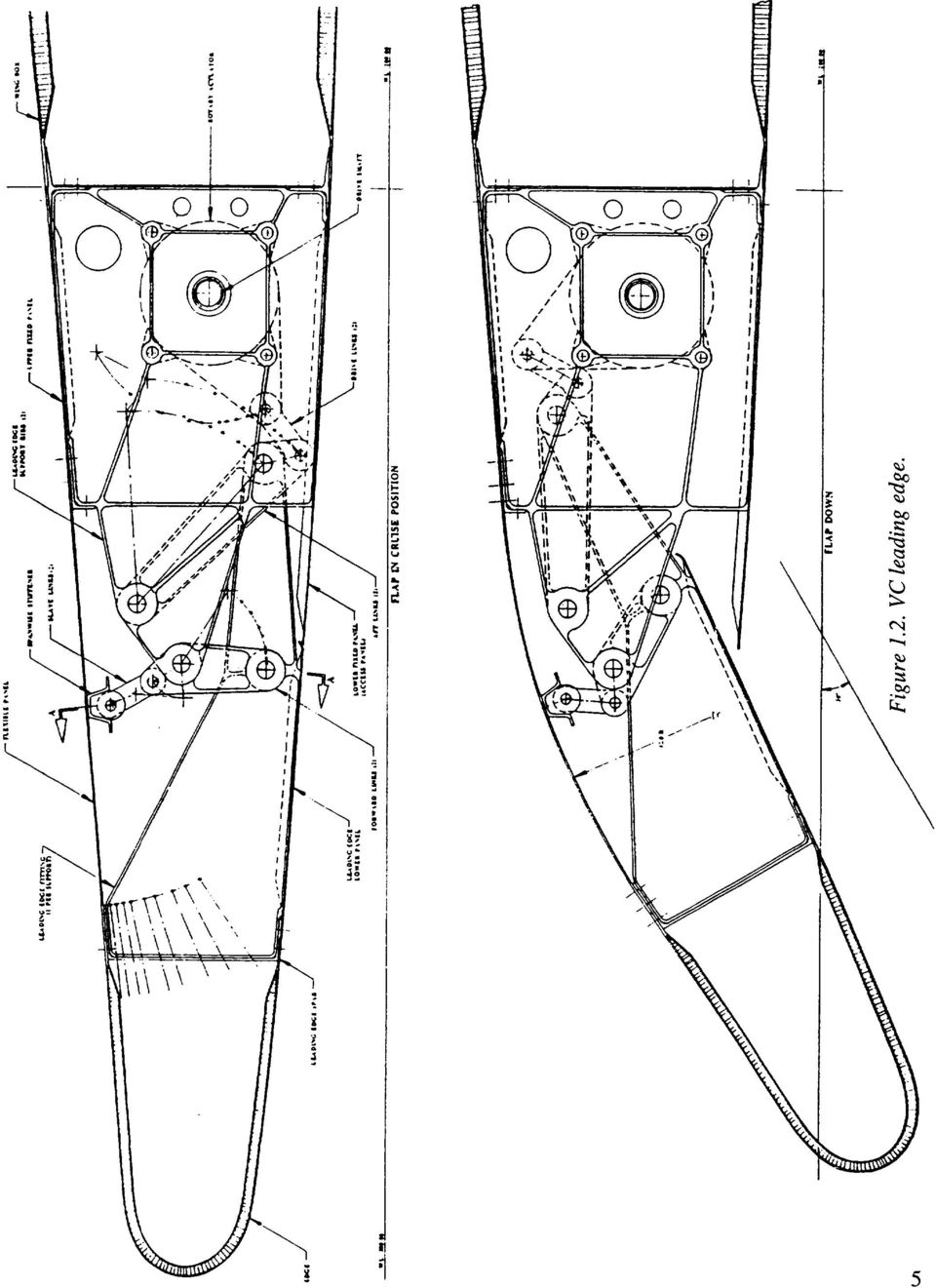
14 Seal _"-_, _._._/_,oge _l 1- Win_! box Wing box --' 'i I. li''ge Hinge / Seal Figure 1.1. Hinged leading edge. Variable-camber leading edge- A VC leading edge was successfully tested on NASA's Advanced Flight Technology Integration (AFTI) 111 experimental airplane. However, because low-speed, high-lift characteristics are not good, it is not in use on subsonic commercial airliners. It may find an application on a future supersonic transport in a dual role as a high-lift device and mission-adaptive wing for subsonic cruise over land. Figure 1.2 shows a VC leading edge for the inboard wing of a supersonic transport. Fixed slot- The fixed slot (fig. 1.3) has been used successfully on short takeoff and landing (STOL) airplanes with slow cruise speeds. The drag penalty of fixed slots is unacceptable for a highperformance subsonic airliner. Simple Krueger flap- The simple Krueger flap (fig. 1.4) consists of a panel on the lower side of the wing leading edge. A hinge on the forward end of the panel allows it to rotate first downward and then forward into a position where its forward edge seals against the lower surface of the fixed-wing leading edge. The panel is at an angle of 60 to 80 relative to a horizontal line. The simple Krueger flap is used on the inboard wing of the Boeing 707. The Krueger flap is the simplest leading-edge device in use on high-performance airliners. Its high-lift performance is adequate for inboard wing sections, but its deficiency lies in its inability to accommodate varying angles of attack. During normal operation, there is generally a stagnation bubble on the upper aft portion of the Krueger panel. Folding, bull-nose (rigid) Krueger- The simple Krueger flap can be improved by adding a folding bull nose to it. Hinged to the aft end in the stowed position, the folding bull nose is a panel that runs the length of the main Krueger panel. It has a D-shaped cross section, and it is connected with a slave linkage that rotates to deploy the bull nose as the main Krueger panel deploys. Because of the 4

15 \ \ Q 0 0 //\\
16 Figure 1.3. Fixed slot. Lea(:ing edge skin Upper skin Fixed L.E. assembly Upper spar Skin I I Duct Spar stiffener Spar web Leading edge flap (retracted) Leading edge flap (extended) Lower access panel I Lower spar i Lower skin Figure 1.4. Simple Krueger flap. rounded bull nose, the folding, bull-nose Krueger is more tolerant to changes in angle of attack. As a result, the flow on the upper surface of the Krueger is attached over a wider angle-of-attack range. Shown in figure 1.5, the folding, bull-nose Krueger has generally been used without a slot between the Krueger and a fixed-wing leading edge. The simple Krueger flap and the folding, bull-nose Krueger flap are generally used as two position devices with the deployed position biased toward an optimum landing configuration (CLmax). A third position that is more optimum for takeoff is 6

17 ACTUATOR FAIRING LINKAGE _I_DJuSTAJILE ) FAIRING RETRACTAIILE Figure 1.5. Boeing 727folding, bull-nose Krueger. possible, but it requires a more complex mechanism or fairing concept. Folding, bull-nose Krueger flaps with improved aerodynamic shapes are possible, and they will be discussed in Chapter 3. VC Krueger flap- Figure 1.6 shows the VC Krueger flap, one attempt to improve the shape of the deployed Krueger flap. The shapes of the simple Krueger flap and the main panel of the folding, bull-nose Krueger flap are dictated by the airfoil shape at the lower surface of the wing leading edge. The VC Krueger changes the main Krueger panel from a rigid to a flexible panel, which improves the airfoil shape of the Krueger dramatically and also improves the aerodynamic performance of the Krueger. This improvement, however, comes with a penalty. The linkage for the VC Krueger is a more complex 4-bar linkage, and the main Krueger panel has to be flexible in a line normal to the wing leading edge. This flexibility is accomplished with a fiberglass panel and only two stiffeners in the form of hat sections parallel to the leading edge. As a result, the bending stiffness of this panel in the spanwise direction is limited. Whereas a rigid Krueger panel with two spanwise hinges can be designed for a span equivalent to the span of a slat (100 to 150 inches, depending on the size of the airplane), the practical span of a VC Krueger panel is limited to about half that. Therefore, about twice as many spanwise panels are needed for a VC Krueger as compared to a rigid Krueger or a slat, thus making the VC Krueger a complicated and expensive device. Rigging problems associated with the flexible panels are also present because the flexible panels tend to distort under high cruise air loads. A careful preloading of the flexible panels is required to avoid panel bulging with panel mismatch, which could cause cruise drag penalties.

18 i.in stop lu-i---_ \ _... I \\...,,,,,,,,, " " m.o, ADJUSIAIIIJ Figure 1.6. Boeing 747 VC Krueger. So far, the VC Krueger flap has been exercised only as a two-position device with the deployed position biased toward an optimum landing configuration. Therefore, the takeoff lift/drag ratio (L/D) is not good. Attempts to make the VC Krueger a three-position device have not been successful. The folding, bull-nose rigid Krueger and the VC Krueger are candidate leading-edge devices for airplanes with hybrid laminar flow. Both types stow in the lower surface of the wing leading edge and allow smooth upper surfaces with suction provisions for laminar flow. Krueger flaps also protect a fixed-wing leading edge from contamination by bugs at low-altitude flying; i.e., the flaps act as bug shields. Airplanes with Krueger flaps generally de-ice the fixed leading edge and not the Krueger flap itself. The anti-icing D-duct with the spray tube in the leading edge of the airfoil limits the geometry of the Krueger linkage. Two-position slat- The two-position slat has one stowed and one deployed position. The original two-position slat was the Handley Page slat, which was mounted on curved tracks, deployed with the help of aerodynamic forces, and stowed with the force of a preloaded spring. This design was also used on the F-84 fighter aircraft. No two-position slats are known to be in use on commercial airliners. The leading-edge slat configuration is shown in figure 1.7.

19 X,,cp-m t_ L_ v_ J i!
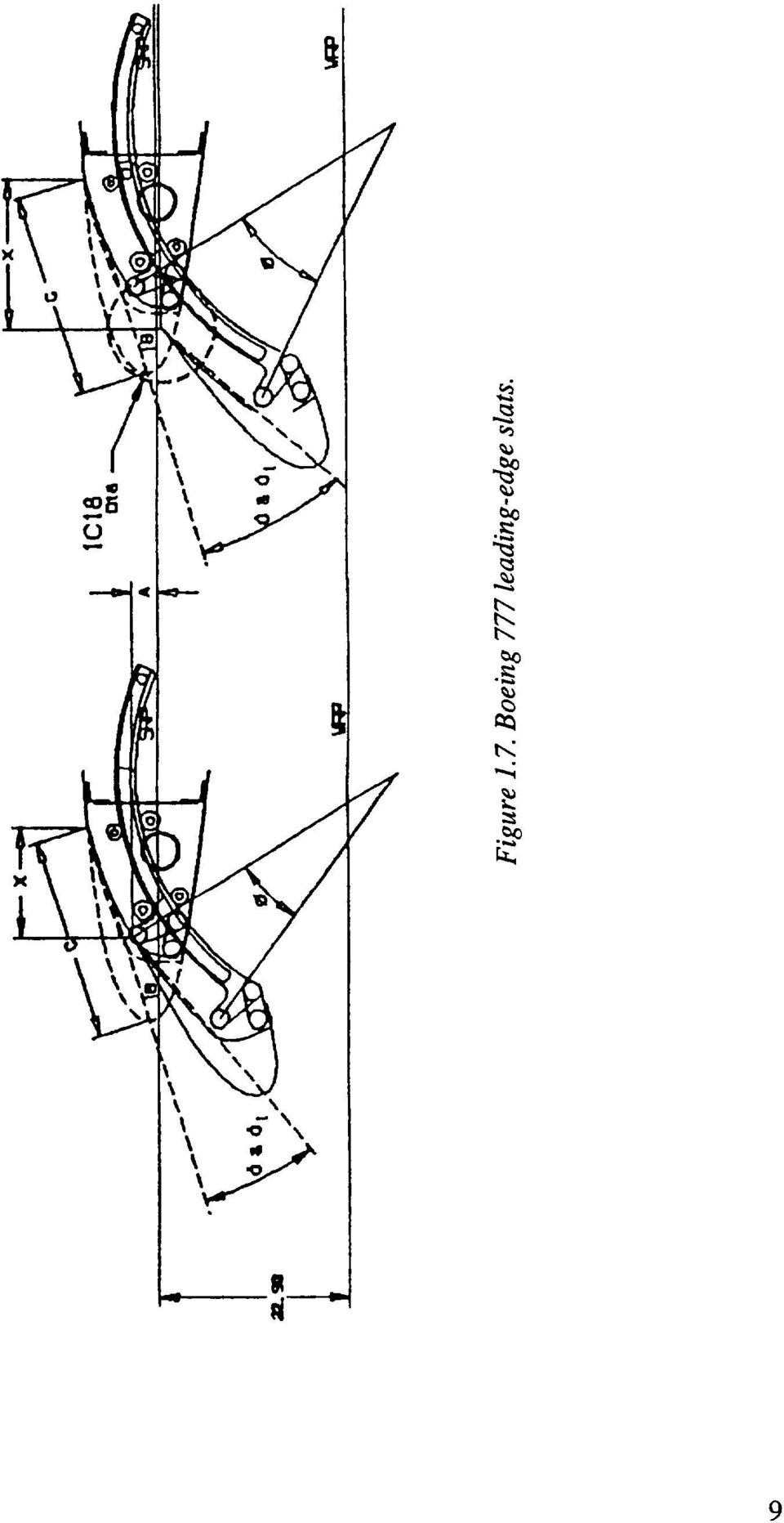
20 Three-position slat- The three-position slat is the most frequently used leading-edge device on the current fleet of commercial airliners. Typically an airplane has 3 to 6 slat panels per wing, and the slat panels form the wing leading edge during cruise. For low-speed operation, they move forward and down on two (or more) circular arc tracks per panel. In its intermediate takeoff position, the slat is at a shallow angle, with its trailing edge sealed against the upper surface of the fixed leading edge for best L/D performance. This sealing is generally accomplished with slave links that run in programming tracks and rotate the slat panel counter to the rotation provided by the circular arc track, which means that the slat is attached to the main tracks with only one pin in each location to allow for this rotation. The programming tracks usually have an S-type curvature. In its landing position, the slat is fully deployed forward to angles of 20 to 38, and the slat trailing edge forms a slot with the fixed leading edge. The slave tracks for slat rotation have been eliminated on some newer airliners, and the slat panels are rigidly attached to the main (circular arc) tracks. Airbus is using an intermediate slat position for takeoff with a shallow slat angle and a small slot on the Airbus A320. On the Boeing 777, the fixed leading edge is shaped such that the slat trailing edge seals in the takeoff slat position Trailing-Edge Devices Possible trailing-edge devices include: Split flap Plain flap Simple slotted flap Single-slotted Fowler flap Fixed vane/main double-slotted flap Articulating vane/main double-slotted flap Main/aft double-slotted flap Triple-slotted flap 10

21 Split flap- The split flap (fig. 1.8)waswidely usedin earlierdays,especiallyon military airplanes. It is a goodattitudeandglideslopecontroldevice,but it doesnot producemuchlift increase. However,asa speedbrakeit is betterthana spoilerbecauseit producesdragwithout losing lift. The split flap is not usedon anymodemairliner. IIIIII II II,,,i... Figure 1.8. Split flap. Plain flap- The plain flap has a panel with a rounded upper leading edge that deploys by downward rotation without opening a slot. The deployment angle is limited to about 20 ; beyond that, the flow separates on the upper surface. Because this restriction limits its lift-producing capability, it is not used on any modem airliner. However, it has come in through the back door--any inboard or outboard aileron that is drooped at low speed (flaperon) is a plain flap. Plain flaps are planned for a future supersonic transport airplane. (See fig. 1.9.) 11
22 q_ I I I 12
23 Simple slotted flap-- Shown in figure 1.10, the simple slotted flap has a flap panel with a fully developed aerodynamic leading edge. It is generally mounted on pivots a little below the lower wing surface and is deployed into a slotted down position of 30 to 35. The simple slotted flap has very little flap overlap with the fixed trailing edge and hence develops only little Fowler motion, defined as aft travel of the flap that increases wing area. Also, the flap motion does not move far enough away from the lower cove panel to develop a good entry into a slot. Therefore, it requires a rounded cavity on the lower surface, which is a solution suitable only for low-speed airplanes. For high-speed airplanes, the lower cove panel has to be rotated upward with a slave linkage, so the simple flap turns out to be not quite that simple. The simple slotted flap is not used on any modern airliner as a main flap concept, but the concept is used for flaperons. Figure Simple slotted flap. 13
24 Single-slotted Fowler flap- When stowed, Fowler flaps have significant overlap between flap and spoilers or the fixed upper cove panel. In the fully deployed position, this overlap is converted into Fowler motion by moving the flap aft, which effectively increases wing area. The single-slotted flap is the simplest of all Fowler flaps and therefore the most attractive one from a weight and cost point of view. With careful aerodynamic design, a single-slotted flap can be deflected to about 40. Single-slotted flaps were widely used in the early days of the jet age, then they were displaced by more sophisticated double- and triple-slotted flaps, and now they are making a comeback. The single-slotted flap on a Boeing 747SP 1 is seen in figure Flap support Figure Boeing 747SP single-slotted flap. 1SP refers to "special performance," which is a long-range version of the Boeing 747 airplane. 14
25 Fixed vane/main double-slotted flap- The fixed vane/main flap has a vane rigidly attached to the main flap, which forms a fixed-geometry slot. When fully deployed, the flap is double-slotted and allows flap deflections of as much as 55. The vane in its stowed position is trapped between the spoiler above and a lower cove panel. Extracting the vane out of this slot imposes restrictions on the mechanism design. The fixed vane/main flap is only slightly heavier and costlier than the singleslotted flap, it produces a little more lift, and it helps adjust airplane attitude on landing approach. For takeoff, it is generally desirable to have the vane sealed against the upper cove panel or spoilers because in this setup only the second slot is open and takeoff L/D is improved. However, with complex vane extraction from the cove and a second geometric constraint of providing a singleslotted takeoff position, very few mechanisms qualify for the fixed vane/main flap. Nonetheless, the fixed vane/main flap is used on many commercial airliners. It is shown on the Douglas DC-9/MD-80 in figure VANE SPOILER / REAR _ I_ '_,,_"_ SPAR I_"" RETRACTED POSITION FLAP / "*''_'"" % \ i DOWN 1 40 DOWN HINGE - 50 DOWN Figure Douglas DC-9/MD-8O fixed vane/main flap. 15
26 Articulating vane/main double-slotted flap-- Making the vane retractable relative to the main flap creates a second overlap that can be used to increase both Fowler motion and the total developed wing chord relative to a fixed vane/main flap. This step is accomplished with no change in the occupying space in the wing. However, the articulating vane/main flap adds quite a bit of complexity to the design. (See fig ) Generally vanes are not actively actuated but are spring-loaded into the deployed position and stowed by the stow stop and the actuating force of the main flap. The structural-vane-to-main-flap connections are generally either straight or circular arc tracks that penetrate the front spar of the main flap. SPOILER ACCESS PAN E L VANE FLAP O \ HYDRAULIC N.. ACTUATOR N. FAIRING Figure Douglas DC-IO/MD-11 articulating vane/main flap. 16
27 If an activemechanismfor movingthe vanerelativeto the mainflap is used,it is easierto provide a single-slottedtakeoffpositionwith the slot in front of the vaneandthe vane-to-main-flapslot closed. However,this configurationreducesfowlermotionavailablefor takeoff andincreasescomplexity. Both fixed andarticulatingvane/mainflapsneed"smart" mechanismsto takefull advantageof their aerodynami capabilities.thechallengeis not only to extractthe vanefrom thecovewithout slave linkages,but to keepthevanein contactwith the upper-covetrailing edge(spoilers)during initial deploymentfor flap anglesof 5 to 15 so that the flap stays single-slotted for typical takeoff settings for best takeoff L/D. Main/aft double-slotted flap- The main/aft double-slotted flap is one step farther in complexity beyond the articulating vane/main flap. The forward or main flap is the larger element and the aft flap the smaller, and the main flap has its overlap with the wing cove while the aft flap overlaps with the aft end of the main flap. Typical flap deflection angles are 30 to 35 for the main flap and 28 to 30 for the aft flap, for a total deflection of 60 to 65. A main/aft flap generally achieves more Fowler motion than an articulating vane/main flap with the same stowed chord length. Thus, it produces slightly more lift and helps adjust airplane landing attitude. This configuration is shown in figure Flap Aluminum track Fairing Figure Airbus A3OOB main aft double-siotted flap. 17
28 Triple-slotted flap- A triple-slottedflap is like anarticulatingvane/mainflap with an additional aft flap addedto themain flap. Sinceit hasthreeoverlaps,it canprovidevery high Fowler motion, andthe threeslotsallow deflectionsof the aft flap to asmuchas80. Becauseall threeof the flap elementshaveto besupportedstructurallyandtheir motionsomehowgearedtogether,the tripleslottedflap is very complexandheavy.it produceshighersectionallift thanthe double-slotted flap, but edgelossesarevery significant(onevortexper flap paneledge).thenose-downpitching momentsarevery high andneedto be trimmedby a tail-download,which furtherreducesits benefits.threeboeing airplanesusetriple-slottedflaps--the 727,737, and747.the Boeing737 with this flap is shownin figure Flap track forward Foreflap fairing Midflap track sequencing carriage Foreflap Midflap carriage Midflap Flap track fairing support arm Aft flap pushrod Bell crank Bell crank cam track \ \ Aftflap cam Fairingtrack "" _3.3 Flap track aft fairing "_ Figure Boeing 737 triple-slotted flap. 18
29 1.2 Support and Actuation Concepts The basic elements to guide and structurally support a moving element such as a flap or a slat panel are hinges, linkages, and tracks. Each panel is generally supported in two spanwise locations with two fixities in each location. Since a statically determinate system needs only three support points, the fourth support point is redundant and creates a potential for force fight. The best spanwise support location is generally at a point about 25 percent of the distance from the ends of a panel, but buried support systems sometimes require supports at the end of the panel. Also, the large spanwise dimension of an outboard flap panel and its limited thickness may require a third support location to avoid making two outboard flaps. The third support location has to be designed to avoid a force fight between flap and wing. Figure 1.16 shows a simple example of such an arrangement for the thin flap panel of a supersonic airplane. A panel with three hinges has two rigid hinges, with the third hinge on a swing link. As the wing box (the stronger and stiffer element) bends under a flight load, the three hinge points go out of alignment, and the swing link of the third hinge can rotate. This process still forces some bending into the flap panel, but the high-stress shear loads in the flap plane are avoided. Actuation of high-lift devices can be done either individually for each support or panel, or it can be geared together with drive shafts powered by a centrally located power drive unit (PDU). For an individual drive, the hydraulic actuator is the most commonly used drive unit. If more than one actuator is used per panel, the panel has to become the synchronizing torque member in case of an actuator force fight due to actuator failure. This situation explains why multiple linear hydraulic actuators are found only on hinged panels or circular arc tracks where the panel can transmit torque. On flap mechanisms that provide good initial Fowler motion (translation), multiple linear actuators cannot be used because the panel translation cannot transmit torque. 19
30 J I _ _ I 20
31 Centrally powered and synchronized actuation systems use screw jacks, rotary hinges, rotary actuators, or rack and pinion drives as actuators. This drive system has become the one most frequently used for trailing-edge and leading-edge flaps because it is the surest and safest way to synchronize flap deployment. Figure 1.17 shows the Boeing 737 trailing-edge-flap drive system. A drive system of this nature has been used on the trailing-edge flaps of all Boeing airplanes since the 707 and on all Airbus airplanes. A similar drive system has been used for leading-edge actuation on all Boeing airplanes beginning with the 747 and on all Airbus airplanes. In addition to the synchronizing nature of the shafts, the high reduction ratios of the gearboxes make the system essentially self-locking. Shafting is generally designed to withstand jam failures. Therefore, additional brakes or no-backs and symmetry-sensing devices are redundant safety features. In other words, this actuation system is the safest one against asymmetric and passive failures. Dual motors on PDUs guarantee functional reliability on demand. Figure Boeing 737 trailing-edge-flap drive system. 21
32 1.2.1 Leading-Edge Devices Krueger flaps- Simple Krueger and folding bull-nose Krueger flaps are generally designed with the hinge inside the wing leading edge and connected to the panel with a goose-neck hinge fitting. An additional slave link is required to rotate the folding bull-nose into the proper deployed position. Actuation can be by a single linear hydraulic actuator, by rotary actuators, or by screw jacks. (See fig. 1.5.) VC Krueger flaps require a four-bar linkage as the support mechanism, with additional linkages for flexing the main Krueger panel and deployment of the folding bull-nose. The VC Krueger flap in its only application on the Boeing 747 uses rotary actuators with a centrally located PDU to actuate the system. (See fig. 1.6.) All Krueger flaps deploy against the forces of the airstream and have a high stowing load at low angles of attack. At higher angles of attack Krueger flaps start to produce lift, which, of course, causes actuation loads to reverse--a situation that is not particularly desirable for safety reasons. Also, the actuation loads for Krueger flaps are fairly high and require powerful actuators, which are heavy. Slats- As mentioned earlier, most slats in service on commercial airliners are mounted on circular arc tracks with two tracks per slat panel. The tracks generally have an I-beam cross section. In the Boeing version, the rollers are engaged with the outside flanges of the I-beam, they are endsupported, and each roller reacts against either a down or an up load. Some Airbus airplanes use larger, cantilevered rollers that roll inside the flanges of the I-beam and react against both up and down loads. The air loads on a slat are essentially normal to the path of deployment by the circular arc tracks. Therefore, the magnitude of the actuation loads is low. Slats see air-load reversal at low angles of attack, generally on the ground. Several different actuator arrangements for slat actuation are used on today's commercial airliners. The biggest number of in-service airliners, the Boeing 727 and 737 airplanes, use a single hydraulic actuator to deploy each slat. Today's design standards indicate that the single actuator is not sufficient, and two actuators are required to avoid racking of the slat panel in the tracks. However, practical experience indicates otherwise: none of the approximately 4500 Boeing 727 and 737 airplanes in service today have slat deployment problems. The slats have a programmed deployment/stow schedule that makes them deploy at different times, and symmetry is maintained with the help of electrical position signaling. Other slat-actuation schemes use rotary actuators with drive links, as on the Boeing 767 and on the inboard slats of several other airplanes, including the Airbus A340. (See fig ) Screw jack drives are suitable as well to actuate slats; they are used on the Airbus A300 and A310 airplanes (fig. 1.19). 22
33 _ Bleed slr duct Track support / /.,.v.,.,o. (titanium) ry actuator Travel stop (tracks 2 and 3) Typical slat 1 drive system Figure l. 18. Airbus A340 inboard slat. Figure l. 19. Airbus A300/310 slat actuation. 23
34 McDonnell DouglasandFokkerusecablesto actuateslats.the slatshavea conicalmotion,so travel at everytrack locationis different.this configurationis accomplishedusingcableswrappedaround drumswith differentdiametersto achievedifferentlengthsof travel.however,this systemhasmany flaws: the difficulties of rigging thecablesandmaintainingpreloadin the system;the largenumber of pulleys;anda concernfor safetysincethis drive systemhasno sureway to lock the slatsin place in caseof actuatorfailure. A DouglasDC-10/MD-11slat-actuationsystemis shownin figure _DRIVE MECHANISM OPERATE_ tats I AND 2 J IGHT AND LEFT/ LEFT OUTBOARD SLAT DRIVE MECHANICAL ASSEMBLY OPERATES SLATS 3 TO 8 DRIVE CABLES FOR SLATS , AND 8 NOT SHOWN_ INBOARD SLAT HYDRAULIC CYLINDERS INBOARD SLATS OUTBOARD HYDRAULIC SLAT CYLINDERS Figure Douglas DC-10/MD-11 slat-actuation system. Lately, the rack and pinion drive (fig. 1.21) has become the most popular drive system for slats. First used on the Boeing 757 airplane, it has been copied by the Airbus A320/321, the A330/340, and the Boeing 777 airplanes. This drive uses a rotary hinge that has an outer rotating case and is configured as a spur gear to drive a rack. This rack is a structural part of the circular arc track, and power comes from a centrally located PDU that also synchronizes the system between right- and left-hand sides of the airplane. 24
35 \ t_ \ \,,,, o '\ \ \\ \ \ \ \ L_ \ 25
36 1.2.2 Trailing-Edge Devices Numerous support mechanisms are known for trailing-edge flaps, and new ones are being invented and reinvented all the time. Leaving out hinges and actuation systems for flaperons and simple flaps for supersonic airplanes, the emphasis here will be on conventional trailing-edge flap mechanisms. Definition of Fowler motion- Before describing trailing-edge flap mechanisms and their relative benefits, it is first appropriate to define one of the major goodness factors, namely Fowler motion. It is not clear how Mr. Fowler defined his motion. Most aerodynamicists today see the significant parameter to be the increase in developed wing chord, which means chord in space and not just the wing chord projected into the wing reference plane as shown in several publications. Using just projected chord change makes the Fowler motion of many flaps negative because the rotation shortens the projected flap chord. So, for this report, Fowler motion is defined as the incremental, developed chord measured in the wing chord plane for slats, as shown in figure _-----_ X s _- Figure Definition of slat Fowler motion. In the figure, FMs = XJCw x 100 (%), where FMs is the slat Fowler motion; Xs is the chordwise translation of the slat; and Cw is the basic wing chord. For trailing-edge flaps with multiple elements, Fowler motion is measured in linear increments in the chord plane of the respective upstream element, as shown in figure Measuring the Fowler motion in linear increments in chord planes is a practical approximation to the real chord extension as measured in a curve on the upper surface of the elements. The Fowler motion for landing, with the flaps in the fully deployed position, is independent of flap linkage, and therefore it is a function only of the flap overlap provided. 26
37 \ Figure Definition of trailing-edge-flap Fowler motion. In the figure, FMTE = (X1 + X2)/Cw x 100 (%), where FMrE is the flap Fowler motion; X1 is the first flap translation in the chord plane of the wing; X2 is the second flap translation in the chord plane of the first flap; and Cw is the basic wing chord. A "smart" flap mechanism provides most of the available Fowler motion in the initial flap deployment at low deflection angles. This area increase at low-flap-angle settings results in the best L/D for takeoff. Simple hinge for Fowler flap- Good performance for a hinged, overlapping flap requires a flap pivot far below the wing surface whether it is a single, vane/main, or main/aft double-slotted flap. The words "simple pivot" used for this arrangement are not accurate; this concept requires a pivot far away from the wing box and requires a fairly deep, fixed hinge fitting. The flap hinge fitting is about the same size, and both fittings are encased in large, flat-sided fairings. (See fig ) The long and narrow hinge fittings cannot transmit the flap side loads, so another side-load reaction has to be provided, either in the form of A-frame-type links or a side-load track. The circular arc motion of a hinged flap develops Fowler motion proportional to the deployment angle. For low deployment angles required for high-gross-weight takeoff, the hinged flap develops little Fowler motion, and it is therefore not the best mechanism for this requirement. The simple hinge is an example of a "dumb" mechanism. 27
38 Yet another bad feature is associated with simple hinges. Hinged flaps are not easily adaptable to streamwise motion on swept, outboard wing trailing edges. The swept hinge axis of the simple hinge flap rotates the aft hinge fairing into a skewed angle inboard and out of the wake of the forward fixed fairing, which produces drag. Also, the inboard end of an outboard flap is not trimmed in a streamwise direction, so the skewed end rib is exposed to full ram pressure when the flap is deployed, producing still more drag (fig. 1.24). This same characteristic makes sealing a swept, outboard flap against an unswept, inboard flap difficult. "_"x----- Exposed Flap End Rib posed Aft Fairing Flap Deployed Hinge Line Figure Deficiencies of simple hinge. Upright, four-bar linkage- The four-bar linkage with upright links reduces the fairing depth by 30 to 35 percent as compared to a simple hinge and improves the Fowler motion schedule. Figure 1.25 shows such a linkage exercised in three variations for a main/aft double-slotted flap. The results are somewhat better than those produced by a simple-hinge, double-slotted flap as used on the Boeing YC
39 ; 10" 18" 0, \,i')'-., 3ao,,l US. Patent 4,353,517 z6_" 38d" (a) Common aft aft link.,zo / I0 / 'i Common Aft/Front Link 26a/ 22 Common Front/Front Link (b) Common front front link. (c) Common aft front link. Figure Variations of upright, four-bar linkages. 29
40 Upside-down, four-bar linkage- The upside-down, four-bar linkage has a much better potential for applications to trailing-edge flaps. The two links at any support location are hinged on a fixed structure at their upper end and to the flap or a flap carriage at their lower end. When used as an end support, the links can be buried completely inside an airfoil, with no need for flap support fairings. This configuration, of course, means lower drag at both low and high speeds. For example, refer to the Boeing 747SP flap shown in figure The upside-down linkage in its more compact form (shortest links) tends to drop the flap down and create some counterrotation during the initial part of deployment. It is therefore not advantageous for a vane/main flap that needs to extract the vane from the slot between the upper and lower cove unless the vane is made small and with little overlap, which is the case on the Douglas DC-8 (fig. 1.26). However, the DC-8 flap mechanism is not a plain four-bar linkage, but rather has the upper pivot of the aft link move aft in a short, straight track. This motion is slave-linked to the forward link. The upside-down, four-bar linkage is good for a single-slotted flap and for the main and aft flaps of a main/aft type double-slotted flap. McDonnell Douglas used this concept again on the YC-15 and the C-17 for blown, double-slotted, main/aft-type flaps (fig. 1.27). Cruise Takeoff Figure Douglas DC-8 four-bar trailing-edge-flap linkage. 30
41 Figure Douglas YC-15 traiiing-edge flap. The Fowler motion progression of the upside-down, four-bar linkage is quite good, achieving high Fowler motion at small flap deployment angles for good takeoff L/D. It is not clear who invented this linkage or used it first on a trailing-edge flap, but it has repeatedly been claimed as a novel linkage. The linkage can be adapted for streamwise conical motion, which is required to allow inboard and outboard flaps to seal against each other. Actuation power requirements can become quite high. 31
42 Upside-down/upright four-bar linkage- Of the two combinations possible within this concept, the arrangement with the upside-down link forward and the upright link aft seems to have the most promise. Whether this concept is better or worse than the pure upside-down linkage is not clear, but at first glance it looks about as good as the other concept. It can be easily adapted to conical, streamwise motion. The fairing size required to house the linkage is fairly deep, but short. Actuation power requirements are, as on the upside-down concept, fairly high. The upside-down/upright, four-bar linkage is used on the Boeing 777 inboard main flap and single-slotted outboard flap (fig. 1.28). Main Drive 7050-T7451 Aft Flap 8 Bolts \ Flap Carrier Beam 7050-T7 _ Flap Pivot Link 2 Segmer_t Fatting Figure Boeing 777 inboard flap mechanism. Complex four-bar linkages- Many recent attempts have been made to design more complex linkages for trailing-edge flaps. The design goal of most of these attempts has been to squeeze another percent or two of additional Fowler motion out of the concept for low-takeoff flap angles. One of the more memorable attempts was called a "walking beam four-bar linkage," where a beam located underneath the flap is moved aft with an upside-down linkage while the flap is moved aft and rotated with an upright, four-bar linkage that rides on the "walking beam." The concept, of course, needs more slave links, and for fail-safety, every link is duplicated. The same linkage is then repeated for the aft flap with more slave links, and, as a result, the number of links and pivot points is about 20 per support location, which makes the concept very expensive to build and maintain. The 32
43 major flaw of this kind of approach is that there are too many joints in series, which increases both the probability of failure and the chance that joint wear will result in a wiggly support. One successful implementation of a complex linkage flap support, best described as a hingedbeam/upside-down/upright, four-bar linkage (fig. 1.29), is used on the Boeing 767 for the main flap panel of the inboard flap and the single-slotted outboard flap. The flap is mounted on an upsidedown/upright, four-bar linkage with the forward, upside-down link hinged on a fixed structure and the upright, aft link hinged on the folding beam. The folding beam itself is hinged on a fitting on the lower surface of the wing box. As the four-bar linkage moves the flap aft and rotates it into the landing position, the hinged beam first moves down and then up. \ \ \ Figure Boeing 767 inboard flap mechanism. This process negates some of the up-and-down motion of the aft link to avoid flap interference with the spoiler and to create proper flap gaps. The concept is ingenious because it creates a lot of Fowler motion at low flap angles. However, it has some of the flaws discussed earlier: The multiple links and joints in series require doubling of most links for fail-safety. This configuration adds to the complexity and cost of the design and makes it difficult, if not impossible, to accomplish streamwise deployment of the flaps. Therefore, the disadvantages of the simple hinge flap apply to the
44 linkage--a slantedendtrim of the inboardendof the outboardflap thatdoesnot allow sealingwith the inboardflap, androtationof theslantedinboard-flapendrib andaft-flap fairing into the free stream.in addition,the duplicatedlinkageis wide andessentiallynormalto the rearspar.hiding this normal linkagein a streamwisefairing makesfor a wide fairing with a lot of slot blockageand reducedflap performance. Hooked-track supports- Before discussing hooked-track supports, a discussion about the Boeing 707 circular-arc-flap support track is in order. This track is located forward of the flap inside the airfoil. It does not provide any fancy motion but deploys the flap from stowed to full extension. This mechanism is light and does not require any flap fairings. Details about this flap mechanism can be found in Chapter 2. Hooked tracks used to deploy the main flaps of successive Boeing airplanes (727, 737, 747, and 757, fig. 1.30) have been quite successful. The forward end of this hooked track is essentially straight and slopes downward; therefore, initial flap motion is aft and slightly down. A good portion of Fowler motion can thus be obtained at low flap angles for takeoff. The aft end of the track is hooked down and accomplishes the major part of the flap rotation for the landing configuration. The hooked-track concept lends itself to conical streamwise flap deployment, which allows a sealed interface between a straight-motion, unswept, inboard flap and a conical-motion, swept, outboard flap. Figure Boeing 757 inboard flap mechanism. 34
45 The majordrawbackof thehooked-trackconceptis thatthereactionto the flap air loads,which are generallyaft of the carriage,resultsin a couplebetweenthefront andaft rollers of the roller carriage.for practicalpurposes,thiscoupleis not very long,andtheresultis very high aft roller loads.therefore,designingrollersandtracksfor reasonableservicelife is not easy. It is not clearwhoinventedthe hooked-trackflap support.in additionto theuseon four Boeing airplanemodels,it is usedby British Aerospaceonthe BAe146andRJ70/100/120airplanesandby Airbus on the A310 airplanes. Link/track mechanisms-most of the linkagesystemsdescribedin thepreviousparagraphshave theproblemthatonelink wantstobe quitelong for idealflap motion anddoesnot fit into the minimum fairing envelope.it shouldbe recognizedthatan infinitely long link canbesimulatedwith a straighttrack. This thoughtprocessledto theevolutionof severalink track mechanisms.for the link/track flap mechanism,the low overturningmomentfrom the flap loadscreatesa couplebetween theroller carriageandthe front link or aft link anddrive rod.this setupreducesroller loadsand providesgoodroller/trackwearcharacteristics.theadvantagesof this arrangementwererecognized atboeing in the late 1970s,but it wasnot vigorouslypursued.airbus is usingtwo of theseconcepts on the Airbus A320/321andA330/340airplanes. Airbus A320 flapsuseanupside-down,forwardlink in conjunctionwith a straight track on a fixed structure as aft support (fig. 1.31). The motion of this mechanism is very favorable for Fowler motion at lower takeoff flap angles and requires very low actuation power. In addition, the mechanism is adaptable to streamwise conical motion. Figure Airbus A320 trailing-edge flap mechanism. 35
46 The A330/340flap mechanismusessimilar elements,but in a differentarrangement;it hasa straight andslopedtrack on fixed structureasforwardsupportandanupright link asaft support(fig. 1.32). Again,Fowler motion progressionis very good,but no betterthanon the A320.Theselink/track mechanismswill bediscussedin moredetailin Chapter3. I Spoiler Front flap link Flap / (fail safe) / \ J 33 Fixed fairing Rotary actualor Track Carriage / Movable fairing Rear flap link (fail-safe Figure Airbus A330/340 trailing-edge flap mechanism. 1.3 Geometric Parameters of High-Lift Devices Leading-edge devices typically extend from wing root to wing tip. Most Boeing and some Airbus airplanes have constant-chord slats, and other Airbus and all McDonnell Douglas airplanes have tapered slats. The significance of constant-chord versus tapered slats on aerodynamic performance is not fully understood. In general, the outboard wing needs more protection from stall in order to maintain roll control. (Stall protection means maintaining aileron effectiveness beyond a stall of the inboard wing.) However, a constant-chord slat (in absolute inches) is probably an aerodynamic overkill on the outboard wing and it is inadequate inboard. The constant-chord slat, or only slightly tapered slat, has the advantage that the same slat mechanism can be used from wing root (or inboard engine location) to wing tip. A highly tapered slat requires variable-radius slat tracks and varyingsized actuators, a very expensive proposition. Slats are deployed to angles of about 15 to 20 for takeoff with either no slot or a small slot; landing slat angles range from 21 to 38, with slots of 1 to 2 percent of local chord. Krueger flaps generally have a constant chord; they are deployed to angles of 70 to 85 for sealed Kruegers and to lesser angles for slotted Kruegers. 36
47 The geometricparametersof trailing-edgedevicesarecomplexto describe.thechordof most trailing-edgeflapsin the stowedpositionrangesfrom 20 to 35percentof local wing chord.flap overlapis generallyabouthalf of flap chord,but it may vary.themaximumdeflectionof a singleslottedflap is between30 and40, with anoptimumflap gapof about2 percentof local chord. Vane/maindouble-slottedflapsdeployto anglesof 45 to 55, with the optimumfirst slot atabout 2 percentandthesecondslotcloseto 1 percentof local chord.flap overlapin thefully deployed positionis not a very strongparameterfor flap performance;its rangeis approximately+1 percent. For main/aft double-slotted flaps, maximum main-flap deflection is similar to the single-slotted flap at 30 to 35 and a first-flap gap of approximately 2 percent. The aft flap can be deployed up to 63 to 70 relative to the wing-chord plane, with the second slot optimizing at approximately 1 percent. Triple-slotted flaps are similar to articulating vane/main flaps with an aft flap added on. Generally, the angles for the vane and main flap are less than those used on double-slotted vane/main flaps, and the aft-flap deflection may be 65 to 80. Flap gaps are typically about 2 percent for the vane and 1 percent of the local wing chord for the main and aft flaps. Geometric parameters for optimum aerodynamic performance during takeoff depend heavily on the airplane wing loading and thrust-to-weight ratio. In other words, it makes a difference whether it is a high-gross-weight takeoff of a long-range airplane on a long runway or a light-gross-weight takeoff of a shorter range airplane on a short runway. In all cases, it is highly desirable that as much of the available Fowler motion as possible is developed, or that the developed wing chord is maximized. For best takeoff L/D at higher gross weights, the maximum flap angle for single-, double-, and triple-slotted flaps optimizes at a deflection angle between 10 and 20 with only one slot open and as much Fowler motion as possible. For low-gross-weight takeoffs at high thrust-to-weight ratios, the takeoff flap setting may approach the maximum landing position. The fact that Fowler motion is so important for high-gross-weight takeoff to maximize L/D leads to the conclusion that trailing-edge flaps need a "smart" linkage that converts the flap overlap into Fowler motion early in the deployment and at low flap angles. In other words, a single-slotted flap with a "smart" mechanism may actually provide a better takeoff configuration than a double-slotted flap with a "dumb" mechanism. 1.4 Design Requirements and Criteria for High-Lift Systems Failure Modes and Fail-Safe Design High-lift system components are generally not primary control surfaces, except in the case of flaperons, but failures of high-lift system components can have serious consequences on the controllability of an airplane. Four failure modes must be considered: structural failure at high speed, structural failure at low speed, failure of the device into the deployed mode at high speed, or failure into the high-speed configuration at low speed. The panels of high-lift system components are usually built similar to wing structures with redundant structural elements, so failures of panels are uncommon. The weakest link of high-lift system components is the panel support and actuating mechanism since each panel normally has 37
48 only two supportswith two attachmentpointseach.structuralfailuresat high speedwith the highlift systemstowedareunheardof becausevirtually all mechanismsutilized havea tremendous mechanicaladvantagein the stowedposition.the load-momentarmsarealsovery shortin cruise, which helpsto keepthe loadslow. Maximumoperatingloadsoccurmostlyduring low-speed maneuverswith the devicesdeployed. To precludestructuralfailuresin this critical, low-speedmodeof operation,the support-structure mechanismis built usingfail-safecriteria: Everycritical structuralelementis duplicated,suchas back-to-backchannelsforming ani-beam,or two side-by-sidelinks, or a pin inside a pin where, afterfailure of onestructuralelement,the remainingstructurecanstill handlelimit loads.this designapproach,of course, adds cost and weight to the system. The consequences of a failure differ vastly, depending on whether it occurs inboard or outboard. Asymmetric failures on the outboard wing, such as the loss of an outboard flap in the landing position on only one side, cause very high rolling moments for which the control system may not be able to compensate. Loss of an inboard flap can generally be handled by the control system, but fail-safe criteria are generally applied to both the outboard and inboard high-lift components. One word of caution is appropriate at this point. When two parts that are supposed to provide failsafety are joined together, the joint has to be designed such that fasteners do not act as fatigue crack starters. If the fasteners are located in a highly loaded area of the part, the fastener holes become generic crack starters, and a crack may start not only in one of the two parts, but in both of them within a very short time. This situation, of course, defeats the idea of the fail-safe concept, and a "safe life" structure would be cheaper and lighter. Another example where redundancy does not provide real fail-safety is the pin inside a pin concept, unless both pins can be readily inspected. Another important consideration for a safe design is to minimize the probability of failure by minimizing the number of parts and joints in series. The classical example of what not to do is the infamous "walking beam four-bar linkage" mentioned earlier. In this design there are about 10 links and 15 joints in series and an equal number in parallel to provide fail-safety. The probability for any failure on this concept is somewhere between 5 and 10 times higher than on a simple 4-bar linkage. The actuation itself has to meet fail-safe criteria. It is generally accepted that a high-lift mechanism that causes loads in one direction only (preferably stowing loads) makes the actuation safer because a slow stowing of high-lift devices at low speed does not lead to structural failure, and any upset can be controlled if detected early enough. Most trailing-edge flap and leading-edge slat mechanisms meet this criterion. Only the K_rueger flaps experience serious load reversals, and they occur during deployment, while being stowed, or during changes in angle of attack. In addition, the Krueger-flap actuation loads are quite high. There is a requirement that a failure of the actuation will allow only a slow retraction of the high-lift devices. This criterion can be met by installing snubbers; better yet, failure can be completely prevented by installing brakes, locks, or making the drive system self-locking through high gear ratios in rotary actuators or screw drives. These kinds of drives generally call for a centrally located PDU with redundant motors that drive the respective high-lift systems on right- and left-hand wings. (See fig ) Such a design prevents asymmetric deployment. In case of a shaft failure on one side, an electrical sensing system stops the drive motors to preclude an asymmetric problem. This 38
49 arrangementis the mostcommonlyusedtechnologyfor leading-andtrailing-edgeflaps onthe most recentcommercialairliners. Someolder airlinersuseddifferent approaches.as mentionedearlier,theboeing727and737 used single,linear, hydraulicactuatorsto deployandstowthe leading-edgeslats.the actuationwas programmedandsynchronizedfrom sideto sidewith electricsensors,andfailureswould affectonly oneelement,so they werecontrollable.thesetwo airplaneshavea cleanservicerecordconcerning critical failuresof slats. The only actuationarrangementnot recommendedis theonewheredifferent PDUsdrive the leftandright-handsidesof a high-lift system(trailing- or leading-edgedevice);if used,this arrangement needsat leasta dual systemto preventasymmetryin caseof a failure Protrusions and Flow Blockage High-speed performance considerations suggest that the wing leading edge be as smooth as possible; in other words, there should be no protrusions for leading-edge-device mechanisms in the highspeed configuration. The high-speed drag penalty for trailing-edge flap fairings is not quite so critical, but having none or only small protrusions is still desirable. Fairings with lowest cruise drag are small and more or less hidden in the trailing-edge cusp on the lower wing surface. Trailing-edge fairings on the upper wing surface are not desirable. Mechanism fairings are always aligned to the local flow direction in cruise to minimize drag. Mechanisms that deploy flaps in a direction other than streamwise (such as normal to a swept rear spar) move the aft fairings, which are attached to the flaps, inboard. This move creates a new frontal area, generally with a forward-facing cavity, that is very detrimental to L/D in the low-speed configuration. In addition, it may also contribute to airframe noise. The nonstreamwise deployment of a trailing-edge flap also exposes the inboard end rib of the outboard flap at an angle to the flow that causes a low-speed drag penalty. Slot blockage is also detrimental to low-speed performance. Blockage of the slots for leading-edge slats and the slot(s) in front of the trailing-edge flaps cannot be avoided because some structure is required to hold on to the high-lift devices. To minimize the adverse effect of the blockage, the structure should be as far away as possible (upstream) from the high-velocity region of the slots. The width and depth of fairings for trailing-edge flap mechanisms should be held to a minimum: Fairings cause cruise drag--the larger the fairings, the higher the drag. With the flaps deployed, the flap supports and fairings cause blockage of flow into the slots, which leads to early flow separation, reduced lift, and lowered L/D Spanwise High-Lift Continuity The spanwise aerodynamic continuity of both the leading edge and the trailing edge in the high-lift mode has a very strong impact on lift and drag, and, of course, directly and indirectly on noise. On many airplane configurations, leading-edge devices are interrupted by engine struts; the gap in the deployed slats leaves the wing behind it unprotected and can cause premature wing stall. Engine 39
50 nacellechinescanhelp to alleviatethis problem,but acompletelycontinuousleading-edgedeviceis preferable. Gapsin the trailing-edgeflapsarecausedby inboardaileronsandby thrustgatesfor wing-mounted engines.thesegapsnot only causelossof lift proportionalto the lossin flap area,but the openends of the flap segmentsshedvorticesandcauseflow separationon thesuctionsideof theflaps nearthe edges.therefore,both thelossin lift andthedragincrementcausedby flap discontinuityarehigh. Also, the flap edgevorticesin all likelihoodproduceairframenoise,so again,continuoustrailingedgeflaps arepreferable. 1.5 Characteristics and Constraints of High-Lift Devices The objective in the design of high-lift systems is to find a match between takeoff and landing field length and to meet the requirements for safe approach speeds and climb rate. Takeoff- Takeoff field length is defined as the total ground roll distance to lift off plus the airborne distance to overfly a 35-foot obstacle. Federal Airworthiness Regulation (FAR) rules specify that lift-off speed, VLOF, has to be equal to or greater than 1.1 times the minimum unstick speed, VMU, which is the minimum speed with which the airplane can safely take off with one engine inoperative. VMU is a function not only of maximum lift capability, but also of rotation: Limits on rotation can reduce the usable lift coefficient and increase VMU, and increased VMU increases the ground run and takeoff field length. The limitation in usable lift can become a real problem for derivative aircraft versions with stretched fuselages. After takeoff and gear retraction, an airplane must attain a safe climb speed, V2, which must be greater than 1.1 times the minimum control speed, VMC, and greater than 1.2 times the minimum dynamic stall speed, Vsmin. The minimum dynamic stall speed is usually about 0.95 times the stall speed in steady flight, Vslg, so that climb speed, V2, has to be greater than 1.14 times Vslg. In terms of lift coefficients, the lift coefficient at V 2, CLV2, must be equal to or less than CLmax/ 1.142, where CLmax is the maximum lift coefficient for the given flap configuration. During secondsegment climb, which begins after the landing gear is retracted, the FAR rule requires a minimum climb rate at V2 with one engine failed. This minimum-climb-rate gradient is 2.3 percent for a twinengine airplane and 3 percent for a four-engine airplane. The climb rate (R/C) is a function of the thrust-to-weight ratio (TAV) and L/D defined by the following equation: R/C = TAV - (L/D) -1 In other words, for a given thrust-to-weight ratio, the climb rate is directly related to L/D. 40
51 Figure 1.33 shows typical lift curves for three takeoff trailing-edge flap settings and a typical envelope of L/D versus CL. The CL versus angle of attack, co, plot shows that, for a certain o_ given by the rotational clearance of the aft fuselage, the minimum unstick speed and hence the shortest takeoff distance can be obtained with the highest takeoff flap setting. However, the L/D versus CL plot shows that this high flap setting would reduce L/D and therefore the airplane climb rate. There is obviously a conflict between the requirements for short takeoff distance and best climb rate with one engine out, which is particularly critical for twin-engine airplanes. Therefore, every optimization of the high-lift system takeoff configuration is aimed at finding a good compromise between the lift capability and the L/D efficiency. / limit L / D _I1 L I TOI 6F_5 TOII 6FzlO" TOm 6F - 15 C L Figure High-lift performance for takeoff. Some of the steps to achieve such a compromise are to have slats rather than Krueger flaps (at least on twin-engine airplanes), and to deploy the slats to an intermediate position with a shallower angle and a small slot or a sealed position. On the trailing-edge flaps it is desirable to have only one slot on takeoff, even if the flap is double- or triple-slotted for landing. A flap mechanism that develops most of the Fowler motion at low flap angles increases lift at a high L/D. Spanwise continuity of the slats and flaps prevents loss of lift and provides the best possible L/D. Minimizing slot blockage by mechanisms and fairings and keeping the frontal and wetted area of the fairings down helps both lift and L/D during takeoff. Landing- The final approach of commercial airliners is flown on a 3 glide slope. FAR roles require that the approach speed be at least 1.3 times the dynamic stall speed for the given flap configuration, VSmin ' which translates to about 1.24 times the lg stall speed, Vslg. Thus the lift coefficient during approach, CL appr, is about CLmax/1.54. Most modem turbofan-powered airliners have no difficulty matching the landing with the takeoff field length; the critical landing parameter is generally approach speed. Some correlation exists between landing accident rate and approach speed, and an economical consideration for tire and 41
52 brake wear calls for limiting the approach speed. Typical approach speeds of today's airliners are between 120 and 150 knots. Another aspect of flight safety during landing is pilot visibility, which decreases with increasing airplane pitch attitude or angle of attack. The pitch attitude during approach also determines how much rotation is available for the landing flare. If the approach attitude is too high, the power of the trailing-edge flaps has to be increased, or the power of the leading-edge devices decreased. The required lift capability during landing determines the power and complexity of the high-lift system. Since the overall space available for the high-lift system is limited by structural and fuel volume considerations, higher lift levels for approach have generally been accomplished by increasing the number of elements (slots) on the trailing-edge devices. Figure 1.34 shows four lift curves. The first is for a clean wing with and without slats; the other three are for a single-slotted flap, a vane/main double-slotted flap, and a main/aft double-slotted flap, all in the maximum landing position. The cruise airfoil stalls at an angle of attack of about 13 to 14. Slat deployment extends the stall angle to about 21 o. The deployment of trailing-edge flaps increases the lift coefficient at a = 0 (CL0) and shifts the entire CL versus ct curve to the left. The approach CL and cx are indicated on the figure; as can be seen, the stall a for these three types of flaps is not very different (between 18 and 21 o). Assuming a side-of-body incidence angle of +3 and an acceptable approach fuselage attitude of +2 for cockpit visibility, the approach a is limited to +5. In this case the main/aft double-slotted flap is 1 better than required and the vane/main double-slotted flap comes very close to meeting the criterion, but the single-slotted flap is deficient by about 2. An airplane with the trailing-edge flap stuck in the up position has a serious approach-attitude problem and needs a lot of overspeed to keep the attitude within reasonable limits. The usefulness of the leading-edge device is dependent on a properly matched trailing-edge flap, and vice versa. 42
53 I Main/_ft I Double Shxted Double Slo tedrap CI Single Slo ted Rap 2O 72 I Figure High-lifi performance for landing. 1.6 Interactions between Leading- and Trailing-Edge Devices Interactions occur between leading-edge devices, the main wing, and trailing-edge devices. As mentioned earlier, leading-edge devices in deployed position delay the stall of the main wing to higher angles of attack. However, a premature stall of a leading-edge device will lead to an early stall of the main wing. Conversely, stall of the main wing (aft stalls first ) will have little effect on the stall of the slat. The trailing-edge flap is fairly insensitive to angle of attack and stall of the main wing, but it is more susceptible to flap deflection angle and slot parameters. Trailing-edge stall has some effect on the stall of the main wing since the suction of the first flap slot reduces the adverse pressure gradient on the aft portion of the main wing. The deployment and strength of the trailing-edge flaps also have an impact on the induced flow angle for the leading-edge devices. The stronger the trailing-edge device, the steeper the upwash angle at the leading edge, and therefore the steeper the deployment angle and the size of the leading-edge devices should be. The opposite is true for weaker trailing-edge devices: These interactions between the elements of a low-speed wing configuration require a lot of fine tuning in the design of the high-lift system elements for optimum match and maximum performance. 43
54
55 Chapter 2 Review of High-Lift Systems on Current Commercial Airliners Valuable information can be obtained by studying the products of competing airplane manufacturers, especially for high-lift systems. Sometimes companies solve the same task with different approaches, and sometimes they copy or re-invent another company's solution. This chapter reviews high-lift systems installed on the most prominent current commercial airliners. It should be noted that some airplanes were left out not because they are of no interest, but because not enough information is available to make detailed comments. 2.1 Boeing Airplanes Seven Boeing airplane models are considered herein: the Boeing 707, 727, 737, 747, 757,767, and the Boeing The Boeing series was developed from the original Boeing series by adding a wing root extension and an inboard fillet flap (fig. 2.1). The has three simple leading-edge Krueger flaps inboard and five midspan and outboard slats installed on each side. The trailing-edge flaps consist of a fillet flap and both inboard and outboard vane/main double-slotted flaps, with an inboard, high-speed aileron/thrust gate between them. The flap mechanism has internal circular arc tracks located between the rear spar and the flap leading edge. The 707 trailing-edge flaps have little Fowler motion; therefore, they permit the use of internal track supports with no need for flap track fairings (fig. 2.2). However, the multiple tracks cut the vanes into segments, leaving gaps in the vanes when they are deployed. These tracks also penetrate the main flap panels Boeing 727 The Boeing 727 airplane has a much more sophisticated high-lift system than the 707 (fig. 2.3). The 727 wing uses an inboard, folding, bull-nose Krueger flap, and four constant-chord slats per side on the outboard wing leading edge. These slats have sealed takeoff and slotted landing positions. Also, the slats are actuated individually by one linear hydraulic actuator per panel, and they are programmed for sequential deployment and symmetry with an electrical signal and feedback system (fig. 2.4). 45
56 OUTBOARO AILERON BALANCE TAll -- OUTBOARD FLAP CONTROL TAll VORTEX GENERATORS ; [E FILLET FLAP LEAOING EDGE LATE 110 PLA_ 0 FLAP ttabilize CTUATED ELEVATOR TAll CONTflOL TAI Figure 2.1. Boeing Figure 2.2. Boeing trailing-edge flaps. 46
57 12 FT. 4 I,N.-._ " I " --_-- -: 14 F'I" FT. 0 IN. I 136 FT. 2 IK IS3 FT. 2 IH Figure 2.3. Boeing
58 _11'1_1 IMI'II_ i LEADING-EDGE FLAP Figure 2.4. Boeing leading-edge devices. 48
59 The trailing-edge flaps are triple-slotted with a high-speed aileron between the inboard and outboard flap sections (fig. 2.5). The main flap is attached to a roller carriage that rides on a hooked track, the fore flap rides on the track, and the aft flap is supported off the main flap. Actuation is through screw jacks powered from a central PDU and drive shafts that provide mechanical synchronization similar to the Boeing 737 flap drive (fig. 1.17). The 727 has three fuselage-mounted engines and, therefore, does not need a thrust gate. Boeing perceived the need for an inboard, high-speed aileron to avoid outboard aileron reversal at high speed, but this aileron ruined the opportunity to have a continuous trailing-edge flap with higher lift coefficients and higher L/D. In the early 1970s, the Boeing 727 fleet experienced a series of landing accidents that were related to high flap drag in the full landing position. In a modification program, use of flaps was restricted. The flap, in its full deployment, is now double-slotted and is deployed to a smaller deflection angle.._',_-- Spoiler ore flap Midflap Aft flap Toggle Flap / Flap track carriage t Figure 2.5. Boeing trailing-edge flaps. 49
60 2.1.3 Boeing 737 The Boeing 737 high-lift system is very similar in concept to the 727 (fig. 2.6). The inboard Krueger flap has a folding bull nose. The three outboard slats on the -100 and -200 models have constant chords, but the chords are slightly tapered on the -300, -400, and -500 models. Each slat is mounted on two circular-arc tracks. Slave tracks are used to achieve sealed takeoff and slotted landing positions. Each slat is individually actuated by a single hydraulic actuator, and the slats are programmed for sequential, symmetrical deployment with an electrical signal and feedback system. \ t,3"-3.6:'(min.) II..IRN IN6 \ i BS 1I/.,.5.9'I WL 286.3_ SBL Figure 2.6. Boeing
61 The Boeing737 trailing-edgeflapsaretriple-slottedbothinboardandoutboard(fig. 1.15).On the -100and-200 models,theinboardandoutboardflaps aresealedagainsthe extendedenginetailpipe to closethe gapbetweeninboardandoutboardflaps.on the-300,-400,and-500models,which havevery close-coupledenginesstrut-mountedforwardof the wing,the triple-slottedflaps havea thrustgatethat is partially closedusingsmalltriangularflipper flaps.flapmechanismsanddrive are similar to 727technology.Maximumflap anglesare38 for the vane,44 for the main flap, and 65 for the aft flap (outboard flaps) Boeing 747 The 747 is the third Boeing airplane to use a sophisticated high-lift system. The wing of this airplane is more highly swept and thinner than that of its commercial predecessors (fig. 2.7). It has Krueger flaps as leading-edge devices, but not over the complete span of the wing; approximately 100 inches of the wing have no leading-edge device next to the side of the fuselage. Then there are three folding, bull-nose, rigid Krueger flaps inboard of the inboard engine, which have a simple hinge with a goose-neck hinge fitting and deploy to a flap chord to a horizontal angle of about 84 (fig. 2.8). These inboard Krueger flaps are sealed against the wing leading edge when deployed. Between the inboard and outboard engines 5 VC Krueger flaps are mounted on 4-bar linkages. The -100, -200, and -300 models have 5 more VC Krueger flaps outboard of the outboard engine, whereas the -400 model has 6 such flaps (fig. 2.8). The VC Krueger flaps deploy to a flap chord to a horizontal angle of about 68, and they form a slot with the fixed leading edge when deployed. Because of span limitations for the Krueger panels, the Boeing , -200, and -300 models have 13 Krueger panels per wing half. The has 14 panels per side or 28 per airplane, with 56 support linkages and actuators per airplane. On the outboard side of each engine-mount strut there is a fairly large gap between the sets of Krueger flaps. Inboard and outboard trailing-edge flaps both have relatively short spans (dictated by engine positions), and they are triple-slotted. The maximum trailing-edge flap deployment angles are relatively low: 23 for the vane, 32 for the main flap, and 52 for the aft flap (outboard flaps). The inboard and outboard flaps are not continuous because they are separated by a thrust gate, which is used as a high-speed aileron. Neither inboard nor outboard ailerons are drooped for low-speed operation. The low aspect ratio and the open ends of the triple-slotted flaps cause many strong tip vortices that are not conducive to high lift coefficients, high L/D, or low airframe noise levels (fig. 2.9). The 747SP, with considerably lower takeoff and landing weights as compared to the other models, has single-slotted trailing-edge flaps inboard and outboard. The flaps are end-supported with a buried, upside-down, four-bar linkage. This trailing-edge flap has simple flap panels and a very simple linkage with no rollers or fairings, so it is light and inexpensive to build and has a welldeserved reputation for its reliability and ease of maintenance (fig. 1.10). 51
62 m II t t _o_ Figure 2.7. Boeing
63 c::_l: :i I,_. _..._.'"-_, A b., a6 53
64 Figure 2.9. Boeing 747 wing, looking outboard Boeing 757 The Boeing 757 abandoned the Krueger flaps and triple-slotted flaps used on the 747 and adopted a simpler high-lift system. (See fig ) The 757 leading edge has three position slats with sealed takeoff and slotted landing positions. There is one inboard slat between side of body and the engine strut and four outboard slats. The slat chord is almost constant with span, which makes the side-ofbody chord about 10 percent and the slat tip chord about 26 percent of wing trapezoidal chord. The slat deployment angle is 28 inboard and 32 outboard. The slats are mounted on circular-arc tracks and the tracks are driven by a rack and pinion drive. (See fig ) Power for the slat actuation comes from a centrally located PDU through spanwise drive shafts to assure slat synchronization. Side-to-side feedback, brakes, and the almost self-locking nature of the rotary gearboxes make it impossible for the slats to be deployed to or to fail into an asymmetric position. Synchronized deployment allows the use of one feeder duct per side for slat de-icing. The 757 slat concept has evidently gained such high marks that it has been copied, with minor variations, on the Airbus A320/321 and A330/340 models and the Boeing 777 airplane. The Boeing 757 trailing-edge-flap concept is also new, but it uses a hooked-track support system, just as do the 727/737/747 triple-slotted flaps. The 757 trailing-edge flap is double-slotted both inboard and outboard. (See fig ) Maximum trailing-edge-flap deflection angles are 34 for the main flap and 60" for the aft flap (outboard flaps). There is no cutout for an inboard aileron, and the outboard aileron is used for low- and high-speed maneuvers. There are, however, single-slotted thrust gates behind the engines. 54
65 i -: / /' I l-l 55
66 2.1.6 Boeing 767 The Boeing 757 and 767 airplanes were developed in parallel; therefore, one would expect a high degree of commonality between the two airplanes. They do share a common cockpit, common airconditioning packs, and many other subsystems, but their high-lift systems are dissimilar. The 767 wing planform is shown in figure The 767 leading edge has three position slats with sealed takeoff and gapped landing positions using programming tracks. There is one inboard slat between the side of body and the engine strut and five outboard slats. The slat chord is constant, and, as a result, the side-of-body chord is about 6.7 percent and the slat tip chord is about 29 percent of wing trapezoidal chord. Maximum slat deployment angles are 30 inboard and 38 outboard. The slats are mounted on circular-arc tracks, and the tracks are driven by drive links from rotary actuators. The PDU and drive-shaft arrangement is similar to the 757 drive and assures slat synchronization. The trailing-edge flaps on the 767 were originally planned to be single-slotted inboard and outboard, but, with the requirement for a high-speed, inboard aileron that interrupts flap continuity, the airplane approach attitude was marginal, especially in view of future weight growth and fuselage stretch. Therefore, fairly late in the development program the inboard flap was changed to a doubleslotted design. Maximum flap deflection angle is 36 for the main flaps and 60.5 for the inboard, aft flap. The 767 design team realized that a mechanism using links rather than rollers (surface contact versus line contact) would produce better wear characteristics. The flap mechanism is described in more detail in section (See fig ) 56
67 _-_- ) / // 3, % t', _,_. / j fi.r \ 57
68 The Boeing 767 trailing-edge-flap linkage can best be described as a "hinged-beam, four-bar linkage." An upside-down, forward link is hinged to a fitting on the rear spar, and its lower end is hinged to the forward end of the flap fitting. The forward link is driven by drive links from a rotary actuator, while an upright, aft link is attached to the "hinged beam" at its lower end and to the flap fitting on its upper end. The "hinged beam" is pinned to the rear spar fitting at its forward end and is linked to the forward-flap link with the drive links. As deployment begins and the aft link starts to push the flap up, the hinged beam rotates downward so that net flap motion is limited to aft translation with very little downward motion. This action produces a slot, and the motion continues to persist for a large portion of flap travel, thus producing a great deal of Fowler motion at low flap angles. For a flap angle of 15 ( maximum takeoff setting), 85 percent of the available overlap is converted into Fowler motion. The "hinged-beam" concept allows the links, in particular the aft link, to be made very short, and the flap fairing required around this mechanism is very shallow. Figure 2.12 shows the flap mechanism for the single-slotted, outboard flaps. _LR SPAR _-.,/_,_ SaOli-E R t_ 0 "" \. /_" /_ OUTBOARD FLAP / \ \.. ---) -. i t 1 SL_ T [ K t_tpig / I / / _. _,,(i.i Figure Boeing 767 outboard flap mechanism. 58
69 Whenthe inboard,aft flap wasaddedat a latestagein theprogram,a simplehingewasselectedto minimize developmentrisk; this hingerequireda deeperfairing.the"dumb" motionof the simple hingedoesnot allow the aft flap to deployfor takeoff, sothe takeoffflap settingcannottake advantageof the full potentialof theaft-flap Fowlermotion.The outboardflap deploysnormalto the leadingedgeof the flap, or skewedabout25 relativeto streamwise,causinga slantedflap side cut with the inboard-flapendrib, which facesthe flow at a 25 anglewhendeployed.the outboard endrib forms a 25 boattail. In addition,the aft-flap fairingsrotateaft andinboardto becomeoffset from the fixed, forwardfairings.thesetwo featurescausedragin the low-speedconfiguration.since the linkageis orientedin a directionnormalto the flap leadingedges,the streamwisefairings for the mechanismhaveto be very wide,andthe wakesfromthesewide fairings causelocal premature separationon the flap suctionside. The Boeing767inboardhigh-speedaileronis droopedfor low-speedoperation.for the , flap performancewasimprovedby addingvortexgeneratorsto theoutboard,single-slottedflapsand increasingflap deflectionto Boeing 777 The Boeing 777 high-lift system takes the best features from the 757 and 767 airplanes (fig. 2.13). The 777 leading edge has a tapered inboard slat between the side of body and the engine strut and constant-chord outboard slats that have 6 spanwise panels. The slat chord is 9 percent of the local trapezoidal wing chord at the side of body and 33 percent at the wing tip. Mounted on circular-arc tracks, the slats are actuated with a 757-type rack and pinion drive. Contrary to previous 3-position slats, the 777 slat has no slave tracks. Sealed takeoff and gapped landing positions are attained by properly shaping the fixed leading edge of the wing. Maximum slat deflection angles are 35 inboard and 31.6" outboard. (See fig. 1.7.) The slats have a gap outboard of the engine strut, and a little Krueger flap on the inboard side of the strut to reduce the slat-to-engine strut gap. The engine nacelle has an inboard chine. As with the 767, Boeing originally planned to use single-slotted trailing-edge flaps inboard and outboard; but when the need for high-speed, inboard ailerons arose, the inboard flap had to be changed to double-slotted. (See fig ) Maximum flap deflection angles are 43 for the main flap and 67 for the aft, inboard flap and 38 for the outboard flap. The flap support mechanism is an upside-down/upright, 4-bar linkage for the outboard flap and the main flap inboard. This linkage is much simpler than the 767 hinged-beam, 4-bar linkage, but it develops very little Fowler motion at typical takeoff flap angles of 5 to 15. This arrangement also dictates that the links are longer, and the mechanism must be covered with a deeper fairing. Figure 2.14 shows an isometric view of a flap support on the single-slotted, outboard flap. This picture illustrates that the size of the supports and links requires a complex structure for this rather simple linkage. The forward links are designed to take side loads, so they are wide and require a wide flap support fairing. The inboard, aft flap rides on hooked tracks below the aft end of the main flap. The aft flap provides some Fowler motion at low flap angles for improved takeoff L/D. The outboard flap deploys streamwise at its outboard support, and it has a slightly slanted trim on its inboard end. The inboard, high-speed aileron is drooped and slotted at low speed to act as a flaperon. 59
70 $ 11,- o -I t < I; \- _+ t_ -- 8i Z. P ++ +, ++. +\ \ s \ \ \ 6O
71 Figure Boeing 777 outboard flap support. 2.2 McDonnell Douglas Airplanes Only the MD-80/87 and DC-10/30 airplanes are discussed in this section MD-80/87 The MD-80/87 is a derivative of the DC-9-50 airplane with a wing root insert and a tip extension (fig. 2.15). Therefore, the following description of the MD-80/87 will cover most aspects of the earlier DC-9 models. It should be mentioned that the original DC-9-10 had no leading-edge device; a slat was first introduced on the DC Also, the DC-9 models have no inboard Yehudi 2 and have continuous trailing-edge flaps. 2A Yehudi refers to a straight portion of the wing trailing edge, which is next to the body. (See figs. 2.10, 2.11, and 2.13.) 61
72 62
73 The MD-80/87 slats (6 per side) are tapered in chord with a slat chord of about 13.6 percent of the local trapezoidal chord at the side of body and 16.5 percent at the wing tip. This highly tapered slat chord requires conical slat motion, which means that every slat track has a different radius of curvature. To accommodate conical motion, slat actuation consists of cables that wrap around different diameter drums, with the drums being rotated by two linear hydraulic actuators. The MD-80s have a centrally located slat PDU with mechanical synchronization from side to side through the cable drives. A picture of DC-10 slat actuation, which uses the same drum and cable system, is shown in figure The MD-80/87 has inboard and outboard, fixed, vane/main, double-slotted flaps mounted on simple hinges. (See fig ) The inboard flaps have cylindrical motion, and the outboard flaps have conical motion around a hinge line approximately parallel to the rear spar of the wing. With one exception, actuation is from one linear hydraulic actuator at each of the hinge locations; the exception is the outboard hinge of the outboard flap, which is unpowered. Synchronization between right and left trailing-edge flaps is through signaling. The outboard edge of the inboard main flap and the inboard edge of the outboard main flap, which have a tendency to gap in the stowed position and to interfere in the deployed position, are trimmed for noninterference, and the gap is closed by a sliding sleeve. The continuity of inboard and outboard flaps and the careful sealing of the flaps are major contributing factors to the good high-lift performance of the MD-80. The hinge fairings are relatively small since the flap has little Fowler motion, so the motion of the aft fairings out of plane is not significant DC-10/MD-11 The DC- 10 models utilize the DC-9 high-lift technology, and the MD- 11, being a derivative of the DC-10, is very similar to it (fig. 2.16). But, because of the wing-mounted engines, the DC-10/ MD- 11 airplanes have a different planform configuration from the MD-80 series of airplanes, with breaks in the leading-edge slats and inboard aileron/thrust gates. These modifications, which break lift continuity, make the DC-10/MD-11 high-lift performance inferior to that of the MD-80. The DC-10 has 2 inboard and 6 outboard slats tapered in chord with a side-of-body chord of about 16 percent and a tip chord of about 19 percent. Slat motion is conical and requires different radius tracks at every support location (16 per side). The slat actuation is accomplished using cables wrapped around different diameter drums, the drums being rotated by 2 linear hydraulic actuators. (See fig ) The two inboard slats are actuated and synchronized by a centrally located drum for both sides. The 6 outboard slats are actuated from a separate drum on either side, so the right and left outboard slats are not mechanically connected, but they are synchronized through a feedback system. 63
74 DC (PROJECTED WING PLANFORU) T_API: SO. FT. \ \ I MAC ZS5.778 (TRAP! GS7.1b'-/ 1 Figure Douglas DC-IO wing, flaps, and slats. 64
75 Inboardandoutboard double-slotted trailing-edge flaps are articulating vane/main, and again the mechanism is a simple hinge. Since the articulating vane provides more Fowler motion than a fixed vane/main flap, the flap pivot has to be a considerable distance below the wing, which makes the hinge fairings quite deep. Inboard and outboard flaps are separated by an inboard, high-speed aileron, which also acts as a thrust gate. Because of high wing sweep, the slant angle on the inboard closure rib of the outboard flap is about 30. When the flaps deploy, the slanted inboard rib exposes a forward-facing surface. The same out-of-streamline angle applies to the aft portion of the hinge fairings when the flap is deployed. (See fig ) Both of these features degrade flap lift performance and cause drag. The actuation of trailing-edge flaps is by one linear hydraulic actuator at every support location, with the flap panels acting as synchronizing torque members. Synchronization of right and left trailing-edge flaps is through signaling only. On the MD- 11, the inboard, high-speed aileron is drooped for low-speed operation YC-15 and C-17 Trailing-Edge Flaps Even though the YC-15 and C-17 transports are not commercial airliners, it is of interest to examine their trailing-edge flaps. Both airplanes use powered lift for short, field performance and therefore have double-slotted, externally blown flaps. In order to extend into the jet stream in the low-speed mode, the flaps have to move down farther than conventional flaps. To make the first slot more effective, the spoilers are also drooped. The flap mechanism used on both the YC-15 and the C-17 is the upside-down, four-bar linkage. (See fig ) 2.3 Lockheed L1011 Little information is available on the Lockheed L1011 high-lift system. There are three inboard slats between the side of body and the engine strut and four outboard slats. The slats are slightly tapered, but it can be assumed that slat motion is cylindrical (identical tracks and actuation travel). The gap between inboard and outboard slats around the engine strut is fairly large. The trailing-edge flaps consist of two inboard flaps and three outboard flaps per side, separated by an inboard, high-speed, aileron/thrust gate. All trailing-edge flaps are articulating vane/main flaps with end supports that consist of tracks and screw jacks housed in small streamwise fairings. The Lockheed L1011 wing is shown in figure
76 66 Figure Lockheed LIO11 wing.
77 2.4 Airbus Airplanes Airbus A300 The original A300B models are currently in service, as is the presently offered A model. The A300 has tapered, leading-edge slats with a chord ratio of about 11.5 percent at the side of body and 20 percent at the tip. There are only three slats per side, and the two outboard slats have a long span that requires three support tracks per panel. The maximum slat deflection angle is 24. As explained in reference 1, slat motion is cylindrical with only one kind of track. The inboard slat has a spring-loaded plug that is pushed aft when the slat hits the engine strut, providing a good seal between the slat and the strut. A small Krueger flap reduces the gap between the inboard slat and the side of body. Slat actuation uses screw jacks that penetrate the front spar. (See fig ) Figure 2.18 shows the A airplane. The A300B inboard and outboard trailing-edge devices are main/aft double-slotted flaps, and the flap mechanism for the main flaps is a set of straight tracks with a slave mechanism to rotate the main flap. The outboard flap has four flap supports, and it appears that the outboard flap panels have a middle structural break to avoid excessive flap loads caused by wing bending. Inboard and outboard flaps are separated by an inboard, high-speed, aileron/thrust gate. Figure 1.14 shows the A300B double-slotted, trailing-edge flap. Figure Airbus A airplane. 67
78 Onthe A model,Airbus deletedthe aft flaps, makingthe flaps single-slotted.the maximum flap deflectionangleis The high-speed, inboardaileronis droopedfor low-speedoperation, andtheoutboard,low-speedaileronof previousmodelswasdeleted Airbus A The Airbus A310 (fig. 2.19) went through evolutionary steps similar to the A300. A310 slats have a very pronounced taper, with a chord ratio of about 17.5 percent at the side of body and 22 percent at the wing tip. The maximum slat deflection angles are 23 inboard and 25.4 outboard. As with the A300, there are only three spanwise slat panels. The two outboard slats have long spans with three slat supports. The slats are probably mounted on identical arc tracks just as on the A300. The inboard slat has a spring-loaded plug to seal it against the engine strut. In addition, an inboard Krueger reduces the gap between the inboard slat and the side of body. Actuation is with screw jacks that penetrate the front spar, and the tracks and screw jacks share the front spar cans. (See fig ) On the inboard trailing edge, the A310 has articulating vane/main, double-slotted flaps (fig. 2.20), but the outboard, trailing-edge flaps are single-slotted (fig. 2.21). The maximum flap deflection angle is 41 for the inboard flap and 31.6 for the outboard flap. Both use a hooked-track mechanism where large, cantilevered rollers run inside I-beam-type tracks; actuation is by screw jacks. The large-span outboard flaps have three supports per panel. Inboard and outboard flaps are separated by an inboard, high-speed, aileron/thrust gate, which is drooped for low-speed operation on the A model. The low-speed, outboard aileron of the original A310 was deleted on the A model Airbus A320 The Airbus A320 started a new approach in high-lift technology for Airbus. Its leading edge has one inboard slat and four outboard slats with very little chord taper. The maximum slat deflection angle is 27. The slats have an intermediate takeoff position with a small gap, and there are no slave tracks. Slat chord is about 10.6 percent of the wing chord at the side of body and 28.5 percent at the tip, which suggests that the slat tracks have a constant track radius spanwise and cylindrical motion. The slat span is such that only two supports per panel are required. The drive system uses a modified Boeing 757 rack and pinion system. (See fig ) No special sealing devices are provided at the engine strut, but the engine nacelles have chines to negate the adverse effect of a slat gap around the engine-mount strut. An inboard slat horn next to the side of body stabilizes the inboard slat edge vortex (ref. 2). As can be seen in figure 2.22, the A320 trailing-edge flaps are single-slotted inboard and outboard, with a maximum flap deflection angle of 40. There is no thrust gate between the inboard and outboard flaps, which seal perfectly in both the stowed and deployed positions. The trailing-edgeflap mechanism is a link/track mechanism with an upside-down, forward link and a straight track on fixed structure as the aft support. (See fig ) The pivot point for the carriage running on the straight track is close to the center of pressure of the flap, so overturning loads on the track are very small, and actuation loads on the drive link are very low. An interesting feature of the A320 flap is that the overlap on the inboard and outboard flaps is constant, suggesting that the flap support mechanism for the inboard and both outboard flap supports are essentially identical spanwise and 68
79 b I _0 69
80 o_ e_ exl 7O
81 oi -I 0 / / / / /! T1
82 Root rib (sealed)! \. I \ i I bay support structure Main structural box 2 skin panels on top surface. 3 Skin panels on bottom surface Slats sections) Sealed ribs Centre section Main landing gear pintle support Flaps (2 sections) Fuel Fuel tank Flap tsu_ Aileron Tracks (3) Figure Airbus A320 wing. from side to side. This feature, of course, reduces production cost. The A320 has a high-/low-speed outboard aileron that does not droop Airbus A321 It is the author's opinion that the growth of the A320 to the stretched and higher growth weight A321 did not go smoothly. The higher growth weight called for larger wing area, and the increase in fuselage length called for a shift to the left in the CL versus (x curve. Therefore, Airbus increased A321 wing area by adding a triangular slice to the trailing edge of the outboard wing and a constant chord increment to the inboard wing (fig. 2.23). However, this wing area increase, which added to the flap chord only, was not enough to satisfy the new aft-body-rotation clearance requirements of the stretched aft fuselage. Since the A320 flap mechanism is not suited to the motion requirements of a vane/main flap, Airbus had no choice but to go to main/aft-type double-slotted flaps. (See fig ) Maximum deflection angles are 36 for the main flap and 60 for the aft flap. The aft flap is fairly small and has limited stiffness for both inboard and outboard panels, so the number of external aft flap supports with fairings had to be increased by 5 per side, for a total of 8 per side. The aft flap on the A321 is mounted on an upside-down/upright, 4-bar linkage, providing some 72
83 Extended chord Irailing edge Figure Airbus A321 wing. Figure Airbus A321 trailing-edge flaps. 73
84 additional Fowler motion on takeoff, which in turn helps improve the takeoff L/D. However, the CLmax is only marginally increased, so the big expense of going to double-slotted flaps helps landing attitude, but helps CLappr only minimally. (See ref. 3.) Airbus A330/340 The wings for the twin-engine A330 and the four-engine A340 are aerodynamically identical. (See fig ) The leading-edge slats are tapered, with a side-of-body chord ratio of about 12 percent and a tip ratio of about 23.5 percent. There are 7 slats per side, with a moderate span for each. The inboard slat has a separate track and drive system with rotary actuators and 3 supports, while the 6 outboard slats have 2 supports each, with constant-radius tracks and rack and pinion drive. Maximum slat deflection angles are 20.6 inboard and 24 outboard. There is a small slat gap at the engine strut locations when the slats are deployed. (See fig ) EXTRA PYLON ATTACHHENT RIB TANK _IB(TYP.) END 73.6 Ildl 7 Figure Airbus A330/340 wing. 74
85 IlnlU) Tn_k l Mwy m_ slats 2 to 7 Tr_ m du_i_ S) Typical Cat 1 drive system Trmcks 2 m' l 3 Figure Airbus A330/340 leading-edge slats. Both the inboard and outboard trailing-edge flaps of the Airbus A330/340 are single-slotted and sealed against each other. The flap mechanism uses the straight track and aft, upright link shown in figure 1.32; the maximum flap deflection angle is 32. There is no high-speed, inboard aileron, and the flap overlap on the inboard and outboard flaps (as on the A320) seems to be constant, which may allow for a common flap mechanism for all flap supports. The inboard flap has 1 buried and 1 exposed flap support, and the outboard flap has 3 exposed flap supports. The outboard flap ends near the centerline of the outboard engine on the A340. The outboard aileron consists of 2 spanwise panels. The inboard panel is a high-/low-speed aileron and is drooped for low-speed operation, while the outboard panel is strictly a low-speed aileron without low-speed droop. 2.5 British Aerospace BAe146 and R J70/80/100 The BAe146 and the RJ 70/80/100 have the same wing, and they are oddities among current commercial airliners. The wing has less sweep than its competitors, and cruise speed is consequently lower. These are the only current high-wing turbofan-powered airliners, and they are among the few without a leading-edge device (old DC-9s and F28s have no leading-edge devices). The BAe 146 wing leading edge is fairly blunt, and despite having no leading-edge device, the BAe146 is a STOL airplane with a very low landing speed (fig. 2.27). 75
86 FLAPS 30 FLAPS I Figure British Aerospace BAe146 airplane and flap details. The BAe146 has very powerful trailing-edge flaps. The flaps are main/aft-type flaps, but the aft flap has only a very small slot, commonly called a tab. Fowler motion is about 25 percent for the main flap and 7 percent for the aft flap, for a total of 32 percent. The high Fowler motion is made possible with a cove extended to approximately 95 percent of wing chord, i.e., a very long main-flap overlap. (See insert in fig ) The BAe146 flap extends continuously from the side of body to about 79 percent of semispan, with 1 internal and 3 external supports per side. Two of the external supports coincide with the engine support struts. The flap support mechanisms for the BAe 146 flaps are hooked tracks. 76
87 2.6 Ilyushin 96 Very little is known about the Ilyushin 96 high-lift system except what can be learned from the Aviation Week picture (fig. 2.28). The inboard flap is a double-slotted, main/aft flap, and there is an inboard, high-speed aileron that is not drooped at low speed. Two outboard, single-slotted flaps have two supports each. The outboard flaps extend to about 80 percent of wing semispan, which is quite a distance outboard of the outboard engine location, and there is no thrust gate for the outboard engine. Figure llyushin Performance Comparison Figure 2.29 shows a high-lift performance comparison of most of the airplanes discussed previously. The approach lift coefficient, CLappr, is plotted versus a characteristic wing sweep angle. Curves are drawn for constant CLappr x cosine of the characteristic sweep angle. The goodness factor, CL, is increasing toward the top of the plot. In a second plot, CLappr is plotted versus wing loading at maximum landing weight. Lines for constant approach speed are shown. In this plot, high lift on approach is toward the top and lower approach speed is toward the left upper comer. No distinction is made between vane/main and main/aft, double-slotted flaps. One would expect to find airplanes with single-slotted flaps at the bottom of the plot, double-slotted flaps in the middle, and airplanes with the most powerful triple-slotted flaps at the top, but this is not so. The lowest and the highest CLappr in this plot comes from single-slotted flaps on the Boeing 747SP and the British Aerospace BAe146, respectively. Although this result is unexpected, there is a rational explanation: The 747SP has two flap sections per side, separated by a large inboard thrust gate that degrades lift on the outboard edge of the inboard flap and the inboard edge of the outboard flap. The trailing-edge flaps cover only 48.5 percent of the wing span, and Fowler motion of the trailing-edge flap is approximately 15 percent. 77
88 \ \ N \ Ill " l. v......=*,*., M i * "_ I n I Jdd. "_ * / i i.0 a_ I el el.g U?8
89 In contrast, the BAe146 has a single-slotted flap without a thrust gate. The flap covers 64 percent of the wing span and has an unslotted aft tab. The combined Fowler motion of flap and tab is about 32 percent. The high wing of the BAe146 helps carry more induced lift across the fuselage than would a low wing. The BAe146 has no leading-edge devices and a very blunt, fixed leading edge, so the main differences are wing planform utilization by trailing-edge flaps, flap chord length, and flap Fowler motion. The Boeing 757 and the Douglas MD-80 show very similar high-lift performance on landing, even though the main/aft double-slotted flaps of the 757s are more potent than the simpler, fixed vane/ main flaps of the MD-80s. The main difference is probably the flap planform configuration: The 757 has a single-slotted thrust gate, while the MD-80 flaps are continuous vane/main, double-slotted flaps that are sealed against each other. Also, the MD-80 tapered slat may have a positive effect on high lift. Numerous airplane pairs could be compared to each other and the differences or similarities explained; discussion of several more to identify significant parameters is probably worthwhile. The DC-10 and the L 1011 have very similar high-lift performance because they have similar leading-edge devices and articulated, vane/main, double-slotted, trailing-edge flaps with a thrust gate. The technology level on both airplanes is about the same because they were developed in the same time frame. The difference in flap mechanism with fairings in between flap segments may explain the slightly poorer performance of the L1011 flaps. The Boeing and 777 have virtually identical CLappr performance because their high-lift configurations are virtually identical. Why does the Airbus A330/340 with single-slotted flaps show CLappr performance very close to that of the Boeing 727? Not only does the 727 have a discontinuous trailing-edge flap, but the major factor here is technology level. The 727 was designed about 1960 and the A330/340 about 1991, a difference of over 30 years, in which aerodynamic technology made tremendous progress. Technology level, however, does not answer the question why contemporary airplanes like the Boeing 777 and the Airbus A330/340 do not have similar performance; i.e., why the Airbus airplanes are doing better with simpler high-lift systems. The reason is not easily explained, and any attempt to do so is politically charged, but the author presents some facts and opinions in the following paragraphs. The Boeing 777 has a thrust gate/high-speed aileron between the double-slotted, inboard and singleslotted, outboard flaps. Even though the inboard aileron is slotted as well as drooped during lowspeed operation, this design is probably not as good as a continuous Fowler flap. Another difference is that the A330/340 has two outboard aileron panels, and the inboard panel is drooped during lowspeed operation. A third difference could be the slat planform: The A330/340 has tapered slats, while the Boeing 777 (with the exception of one inboard panel) has constant-chord slats. It is hard to determine whether this difference accounts for the entire variation in performance or whether there is also a difference in aerodynamic technology, such as better optimization for flight Reynolds number. 79
90 Approachspeedsatmaximumlanding weight,plotted in the fight-hand chart, range from 117 knots for the BAe146 to 146 knots for the Boeing and the DC The new breed of competing long-range jets, the , 777, A330, and A340, have approach speeds of knots. The Airbus airplanes have a somewhat higher landing wing loading than the contemporary Boeing airplanes, but they make up for it with a little higher CLappr. The short-to-medium-range airplanes have approach speeds between 130 and 135 knots. Some of the higher-gross-weight stretched models such as the MD-87 and the Boeing are a little faster; the A321 is off the chart to the right with a very high landing wing loading, beyond that of the A High-Lift System Impact on Noise The high-lift system has an impact on airplane noise as well as on airplane performance. The direct impact of airframe noise is presently being studied, and there are few published results. Airframe noise comes from vortices and other turbulence resulting from fluctuating, separated flow regions and resonance in cavities open to the flow. High-lift-system noise also impacts airplane L/D and, hence, engine power setting. Sideline takeoff noise is, of course, not impacted because takeoff engine power is not influenced by L/D. Takeoff noise with engine power cutback may be affected slightly because the L/D in the takeoff configuration has an impact on airplane height over the measuring station and/or the percent of engine cutback. It should be said here that most multislotted flaps are deployed only to a single-slotted configuration during takeoff, and the differences in L/D for different high-lift configurations are, therefore, small. One exception may be the beneficial effect from a "smart" linkage that provides high takeoff Fowler motion. The planform configuration of leading- and trailing-edge devices will impact the takeoff L/D, with continuous configurations showing better L/D than slats and flaps with spanwise gaps. Landing configuration L/D, however, can be significantly influenced by the type of high-lift system. For example, the Boeing with low-aspect-ratio, triple-slotted flaps and vortices trailing off three flap panels at the two thrust gates and the outboard ends is bound to have a low L/D in the landing configuration. Also, steep Krueger flaps with spanwise gaps produce drag at low incidence angles during approach; therefore, the engines have to be at a relatively high power setting to maintain the three-degree glideslope on final approach and, hence, produce more noise. In contrast, the Airbus A330/340s with continuous single-slotted flaps should have a considerably higher approach L/D and require a lower engine power setting; hence they will produce less noise. Some of these differences can be seen in figure 2.30, which shows approach noise for a variety of airplanes. These data have to be treated with caution: The effect of engine noise cancellation technology, nacelle noise treatment technology, and airplane configuration effects on noise propagation must be considered for each airplane. An example is the noise difference between the A330 and the A340, which have essentially the same aerodynamic landing configuration; this difference in approach noise must come from the difference in engines. 80
91 _eo DC-9-32 DC-10-_ B STAGE 3 LIMIT o _O _ IOC ,.400 _ oo '"-. Z 95 \",_,<^34o-200 A3_-_o------,----^nl-,oo \\\ ^3_ 737--,m_STR \\ "767--_0ER.M _-_ \/ "A310 '_ MD-$! 9C 85 IN--SERVICE STUDY ] 8O 5O TAKEOFF WEIGHT (K-lbs) Figure Comparison of approach noise. 2.9 Lessons Learned from Review Leading-Edge Devices Table 2.1 summarizes the types of leading-edge devices used on airplanes manufactured by the three leading airplane companies. This chart shows that slats are clearly the favorite leading-edge device, even though the use of folding, bull-nose Krueger flaps on inboard wings in the earlier stages is evident. The big question that arises on leading-edge devices is whether slats should be of constant chord or tapered for best performance and/or lowest cost. Slat evolution has definitely shown that a circular-arc track and rack and pinion drive actuation is the best choice, because this configuration has been used repeatedly since its conception on the Boeing 757 and subsequently used on the Boeing 777 and the Airbus A320/321/319 and A330/
92 Table2.1.Applicationof leading-edgedevices Boeing McDonnell Douglas Airbus 707 Simple Krueger DC-8-3-positionslats A300 3-positionslats** positionslats** 60/70 DC-9-10 None A310 3-position positionslats** DC-9-3-positionslats* A320 3-position 747 VC Krueger 30/50 MD-80 3-positionslats* A321 3-positionslats*** positionslats* DC-10 3-positionslats* A330 3-positionslats*** positionslats* MD positionslats* A340 3-positionslats*** positionslats*** *With slavetracks. **Inboard, folding, bull-nosekrueger. ***Without slavetracks. Anotherkey criterion for high-lift performanceis the spanwisecontinuityof the high-lift devices. Spanwisecontinuity affectsmaximumlift coefficient,l/d at takeoffandon landing,andairframe noise Trailing-Edge Devices The evolution of trailing-edge flaps has gone from simple to complex and back to simple again, at least at Boeing, as shown in table 2.2. However, the move back to the simple concepts seems to be more difficult than the move in the direction of complexity. Only Airbus has managed to develop airplanes with single-slotted flaps. Evidently, the tendency seems to be that all airplane manufacturers realize the benefits of simpler high-lift systems, but they have not been completely successful in reaching their goals. The tendency in the field of trailing-edge-flap mechanisms is away from hooked track in favor of simple linkages or link/track combinations, as shown in table 2.3. Trailing-edge-flap spanwise continuity is just as important as leading-edge-flap spanwise continuity. Table 2.4 summarizes trailing-edge-flap continuity criteria for the family of airplanes of the three major airplane manufacturers. Goodness is having more "Nos." Only the Douglas DC-9 and MD-80 and the Airbus A320 and A330/340 airplanes can claim a clean record of three "Nos." 82
93 Table2.2.Applicationof trailing-edgeflaps Boeing McDonnell Douglas Airbus 707 Fixedvane/maindouble DC Triple-slotted DC Triple-slotted DC Triple-slotted MD Main/aft double MD Main/aft doubleinboard,* single-slottedoutboard 777 Main/aft double inboard,*** single-slotted outboard Fixedvane/ A300-B maindouble Fixedvane/ A300- maindouble 600 Articulatingvane/ maindouble Fixedvane/ maindouble Articulatingvane/ maindouble* A310 A320 A321 A330 A340 Main/aft double Single-slotted* Articulating vane/main inboard,*singleslottedoutboard Single-slotted Main/aft double Single-slotted** Single-slotted** *Droopedinboardaileron.**Drooped outboardaileron.***drooped andslottedinboardaileron. Table2.3.Applicationof trailing-edge-flapmechanisms Boeing McDonnell Douglas Airbus 707 Internal track DC-8 Internal four-bar A300 External straight track linkage 727 External hooked track DC-9 External hinge A310 External hooked track 737 External hooked track DC- 10 External hinge A320 Link/track mechanism External hooked track MD-80 External hinge A321 Link/track mechanism 1 747SP Four-bar linkage MD-81 External hinge A330 Link/track mechanism External hooked track MD-11 External hinge A340 Link/track mechanism Complex four-bar linkage 777 Simple four-bar linkage 83
94 Table2.4.Trailing-edge-flapcontinuity Boeing McDonnell Douglas Airbus Inboard Inboard Outboard thrustgate aileron thrustgate 707 Yes Yes Yes 727 No Yes No 737 Yes No No 747 Yes Yes Yes 757 Yes* No No 767 Yes Yes** No 777 Yes Yes** No DC-9 No No No MD-80 No No No DC-10 Yes Yes No MD-11 Yes Yes** No A300 Yes Yes No A310 Yes Yes** No A320 No No No A321 Yes* No No A330 No No No*** A340 No No No*** *Single-slottedthrustgate. **Droopedlow speed.***drooped outboardaileron Boeing Summary The Boeing 707 high-lift system was a good state-of-the-art approach in the early 1960s, especially the fixed, vane/main, trailing-edge flaps. Boeing never utilized an improved version of the 707 trailing-edge-flap system on later airplane designs. The development of the outboard, leading-edge slats, however, was carried over to the 727 and 737 airplanes. Boeing increased the complexity of its high-lift systems by going to triple-slotted trailing-edge flaps on the 727, 737, and 747 airplanes. Of these three airplanes, only the 737 triple-slotted flap performs well enough to justify the complexity. The change to outboard, three-position leading-edge slats was a good move, but the 727 and 747 trailing-edge-flap performance potential is ruined by the discontinuity from the inboard, high-speed ailerons. The triple-slotted flaps also started the use of the complex hooked-track concept as a trailing-edge-flap mechanism. This mechanism had its drawbacks because of the complexity in manufacturing and inherent problems with track and roller wear and reliability. Roller and track wear is caused by the load magnification that results from the flap loads that create a fairly short roller couple on the flap carriage. The 747 VC Krueger has only a small performance advantage in maximum lift over a three-position slat, and its complexity cannot be justified. 84
95 The 757markedthe beginningof a returnto simplerhigh-lift systemsby the inventionof a leadingedge slat with rack and pinion drive (a good concept that was copied quickly by several Airbus airplanes and the 777) and by the development of a double-slotted, trailing-edge flap with a refined hooked-track flap mechanism with improved wear characteristics. A single-slotted thrust gate degrades lift and L/D, but not as badly as an inboard aileron. Neither the 767 nor the 777 met their goal of using single-slotted flaps inboard and outboard. In both cases the need for an inboard, high-speed aileron was the reason. Also, both airplanes discarded the concept of hooked tracks as trailing-edge-flap supports. Although the 767 linkage concept is a very "smart" system with excellent Fowler motion progression, it is executed too conservatively, in particular, the motion normal to the rear spar. The 777 trailing-edge flaps make good use of the simple upside-down/upright, four-bar linkage, but the links are fairly deep and require deep fairings. The inboard, aft flap uses a track system that provides additional Fowler motion for takeoff. The new three-position 777 slats without program tracks are a welcome simplification. The more-or-less constant-chord slats on most Boeing airplanes are probably optimum for cost reduction but not for high-lift performance McDonnell Douglas Summary McDonnell Douglas has shown persistence in the design of their high-lift systems, from the DC-8 to the DC-9, the DC- 10, the MD-80, and the MD- 11. All these airplanes have vane/main, doubleslotted flaps and, except for the DC-8, use "simple" hinges to mechanize trailing-edge flaps. The simple hinge can be justified on the DC-9 and MD-80 where the fixed, vane/main, double-slotted flaps have only modest Fowler motion and hinge fairings are small. The trailing-edge flaps of the DC-9 and MD-80 have good spanwise continuity and, therefore, perform very well. On the DC-10 and MD- 11 with increased Fowler motion of the articulating vane/main flap, the "simple" hinge is a liability in fairing drag and unobtainable Fowler motion for improved takeoff L/D. The inboard, high-speed aileron degrades the trailing-edge-flap performance as well. The tapered slats found on the Douglas airplanes probably are a good match for aerodynamic performance, but the slat mechanization has its drawbacks: First, the multitude of different radius tracks add to manufacturing cost. Slat actuation by means of cables is complex and must be very difficult to rig, but most importantly, this design has potential safety problems. The DC-9/MD-80 arrangement with one central actuation location is probably not too bad from a safety point of view if a proper braking system is provided. The DC-10/MD-I 1 actuation with the inboard slats tied together is acceptable. But, from a safety point of view, the independent actuation of the outboard slats could cause an asymmetric deployment or inadvertent stowing of the outboard slats. This situation may lead to an uncontrollable, asymmetric wing stall Lockheed Summary The one lesson that can be learned from the L1011 trailing-edge-flap concept is that shorter-span trailing-edge flaps can be supported from their ends with very little discontinuity from the flap track fairings. 85
96 2.9.6 Airbus Summary Analysis of the development of high-lift systems on various Airbus airplanes is worthwhile; important tendencies to observe are the aerodynamic concepts and mechanism designs that strive for simplicity. For example, Airbus used main/aft, double-slotted flaps on the A300B models. The next airplane, the A , used articulating vane/main flaps inboard and single-slotted flaps outboard. The A changed to single-slotted flaps inboard and outboard, and deleted the outboard aileron, as did the A The A320, A330, and A340 have single-slotted inboard and outboard flaps. As far as trailing-edge-flap mechanisms are concerned, Airbus started with a straight track and then used hooked tracks. Contrary to Boeing, however, they let each cantilevered roller react against uploads and downloads by letting it roll inside the track I-beam, whereas Boeing prefers to use endsupported rollers on the outsides of tracks for loads in only one direction. The fh'st link/straight track mechanism was introduced on the A320; the A330/340 uses another link/straight track arrangement. Both of these mechanisms have lower roller loads than encountered on hooked tracks because the multiple rollers of the carriage do not react against moments; instead, the rollers work in unison to reduce loads. The overturning moment is low and reacts in a long couple between roller carriage and drive link; therefore, the actuation moments are low. Airbus' slats started out with some taper on the A300/310 models, went to almost constant chord on the A320, and then went back again to some taper on the A330/340 models. Is this a trial-and-error process in work? The motion on the tapered slats is cylindrical, and the A300/310 slats are actuated by screw jacks. Starting with the A320, Airbus slats use a modified Boeing 757-type rack and pinion drive. The development of high-lift systems at Airbus was not always successful. During the development of the A321, it became obvious that A320 trailing-edge flaps were not adequate for the increased weight and fuselage stretch. The small, aft flap that was used to correct the problem may easily double the cost of the trailing-edge flaps, and it cures only the attitude problem of the airplane. The CL max is hardly improved, so the A321 approach speed is quite high for a short-to-medium-range airplane British Aerospace Summary The BAe 146/RJ70/80/100 airplanes all have the same high-lift system. This example shows that, by making the trailing-edge device really powerful, the need for a leading-edge device disappears. The technology could be applied to future small, short-range aircraft, but the concept will not work quite so well on low-wing airplanes. 86
97 Chapter 3 Conceptual Studies for Improved High-Lift Systems 3.1 Summary of Studies The author's involvement in high-lift-system design started with studies of upper-surface, blown flaps on Boeing's entry into the U.S. Air Force (USAF) competition for the C-130's successor-- the advanced medium STOL transport (AMST). The Boeing entry, the YC-14, used upper-surface, blown flaps (USB) for powered lift. This prototype had a two-element flap for upper-surface flow deflection, with both elements having simple hinges. The aerodynamics group proposed a change to a single-element, thrust-deflection flap with a spiral-curved upper surface for the production C-14 airplane. The mechanism to keep the spiral-curved flap surface in contact with a fixed cove panel was envisioned to be a cam, a highly undesirable mechanism. Studies showed that a simple, upright, four-bar linkage would be better, and that the flap fairing depth could be reduced by about one-third over that of a simple hinge (fig. 3.1). This proposal was approved and tested successfully for the potential C- 14 production airplane. rap 78 _ 6_ US. Patent 4,283,029 Figure 3.1. USB flap for Boeing C-14 AMST transport airplane. 87
98 Thesefindings triggereda studyof how to use uptight, four-bar linkages to reduce fairing depth of the YC-14 outboard, trailing-edge flaps, which also had simple hinges. The three configurations that were developed (fig. 1.25) show that a four-bar linkage can reduce the fairing depth of a simple hinged flap by about one-third and improve the Fowler motion progression for takeoff. However, improvement was not sufficient to pursue this concept further. In the meantime, another challenge on the YC-14 prototype arose, specifically, how to improve the deflector-door thrust reverser. This thrust reverser was not fail-safe and was potentially a fatal threat if accidentally deployed in flight. The solution to make it fail-safe and in-flight operable was to design a cascade-type thrust reverser with an internal clamshell door. In order to get the tight motion for this door, i.e., make the cascade thrust reverser opening big enough and the door motion fail-safe (stowing loads), the clamshell door first had to be moved aft before starting the rotation to close the nozzle. It appeared as if an upright, four-bar linkage would work, but the forward link cou]d not be made long enough to fit into the available cavity. The solution was to change the forward link to a straight track, which simulates a link with infinitely large radius. In this way the link/straight track mechanism evolved (fig. 3.2) /2 US. Patent 4,183,478 Figure 3.2. Boeing YC-14 in-flight operable thrust reverser. 88
99 This mechanismwastried for the mechanizationof trailing-edgeflaps, andit showedvery encouragingresults.interestingly,this mechanismhasbeenre-inventedby Airbus for the A330/340 trailing-edgeflaps. Othercombinationsof a link anda straighttrackwerestudied,andthe combination of anupside-down,forwardlink with a straighttrackmoving with theflap wasfoundto be very attractive,in particularfor usewith a vane/main,double-slottedflap. The authorhasbeeninvolvedwith thefollowing additionalstudiesandprojectsrelatedto high-liftsystemdesign: The AFTI 111missionadaptivewing,developingconceptsfor VC leading-andtrailing-edge devices(seefig. 1.2for VC leadingedge) Developinga simple wayto achieveconicalmotion onleading-edgeslats A shallow,slotted,rigid Kruegerflap with folding bull nosethat showedgoodaerodynamic performancefor the757hybrid laminar-flow-control(hlfc) experiment Thepossibilityof changingmain/aft,double-slotted,trailing-edgeflapsto simpler,fixed, vane/main,double-slotted,or evensingle-slottedflaps (thetrailing-edgeflap mechanismsused on today's airlinerswereinvestigatedto determinetheir relativemerits) The following sectionssummarizedetailedresultsof thesestudies. 3.2 Leading-Edge Devices Krueger Flaps There is a big difference between a simple Kmeger, a folding, bull-nose Krueger, and a VC Krueger. The simple Krueger is a hinged, almost flat panel that folds out from the wing lower surface into a very steep, deployed position and seals against the wing leading edge (fig. 1.4). It provides some stall protection, but since the Kmeger leading edge is not rounded, the flow is attached to the panel over only a small range of angles of attack. The 727-style Krueger has a small, folding bull nose that allows attached flow over a somewhat larger angle-of-attack range, but the curvature of the bull nose is not good enough to keep flow attached over the entire 727 angle-of-attack range (fig. 1.5). The 737 Krueger has a much larger folding bull nose, which gives it somewhat improved performance at lower angles of attack. The 747 inboard, rigid Krueger (fig. 2.8) also has a larger bull nose. All these folding, bull-nose, rigid Krueger flaps are deployed to very steep angles, and they are sealed, so they are not lifting (or they are barely lifting) at normal takeoff or landing attitudes. It is not clear why no one has tried to develop a folding, bull-nose Krueger flap that deploys to a shallower angle to provide a slot to make it perform more like a slat. The outboard 747 leading-edge flaps are folding, bull-nose, VC Kmegers (figs. 1.6 and 2.8), which deploy to a shallower angle and show a lot of curvature on both the bull nose and the flexible panel. The flexible-panel trailing edge forms a small slot with the fixed leading edge. The VC Krueger 89
100 providessomewhatbetterclmaxperformancethana goodslat,but it hasa poorer takeoff IJD performance than the slat. The VC Krueger, contrary to the rigid Krueger, is quite complex and heavy. Panel flexing and deployment to a shallower angle require a complex four-bar linkage. The lack of spanwise rigidity requires about twice as many spanwise elements as are required for slats or rigid Kruegers. Therefore, the VC Krueger cannot be recommended because it is too complex, too costly, and too heavy. For the 757 HLFC experiment under a NASA/Air Force contract, a Krueger flap was needed for high lift and for protection of the leading edge against insect contamination (fig. 3.3). A slat was ruled out because its aft step would have caused boundary layer transition and would have made laminar flow downstream of the front spar impossible. The insect protection requirement called for the Krueger to extend above and below the fixed leading edge, or a position that resembles that of a deployed slat. Therefore, the Krueger had to have a slot and a very large bull nose. Suction ducting requires a lot of space in the leading-edge section, so there was inadequate space for a large bull nose and the Krueger linkage. It was therefore decided to make the bull nose large but let the linkage cut through the stowed bull nose. There was no measurable performance deterioration for the resulting slots in the deployed bull nose, and the Kmegers showed aerodynamic performance very similar to slats. The rigid Kruegers on the 757 HLFC experiment were built to the same spanwise dimensions as the slats they replaced, so there is no span penalty as there is with flexible panels. Figure 3.3. Krueger flap for 757 HLFC experiment. 90
101 Sincetherigid Kruegerwith folding bull noseis cheaperto build andlighter thana slat,the concept developedfor the 757HLFC experimentcould not only be appliedfor hybrid laminarflow, but it may alsobe usedto promotemorenaturalaminarflow on futuretransportairplanes.the only concernis whethertakeoffl/d is goodenough Tapered Slats and Conical Slat Motion As was pointed out in the review of competing airliners, McDonnell Douglas uses tapered slats with conical slat motion; Boeing uses essentially constant-chord slats with cylindrical motion, whereas Airbus changed from tapered slats to constant-chord slats and back to slightly tapered slats. To reiterate the differences: Cylindrical slat motion of nearly constant-chord slats allows the use of identical slat tracks and a simple actuation system for an overall savings in complexity and cost. Conical motion of tapered slats by today's standards requires that all slat tracks have a different radius and a complex actuation system with high manufacturing cost. No details are published, but one can speculate that tapered slats provide high-lift performance advantages over constant-chord slats. Figure 3.4 shows how ridiculous an inboard slat with a 9-percent-chord ratio (typical for a constant-chord slat) looks. The slat looks like a crescent moon, and the flow into the slat-to-wing slot has a difficult time negotiating all the turning. A huge area of flow separation on the backside of the slat will almost certainly result. 1 Inbotnl Slat with lyi_ Cbocd Katio Figure 3.4. Inboard-slat shapes. A slightly tapered slat with a longer inboard chord would improve slat shape and could prevent premature stall of the inboard wing. At the same time, a slightly higher-percent-chord outboard slat in conjunction with wing-tip twist still provides tip stall protection beyond root stall for the right pitchover characteristics and roll control during stall. Therefore, a slat with an inboard chord ratio of 91
102 approximately 15 percent of the trapezoidal chord and a wing-tip chord ratio of about 22 percent may be a perfect match for a given wing. The revised shape of an inboard slat with a chord ratio of 15 percent of the local trapezoidal chord is shown in figure 3.4. Studies have indicated that installing constant-arc tracks in the lowest possible location of the airfoil inboard and outboard produces a certain amount of pseudoconical motion on the slat upper surface (fig. 3.5). Hence, a certain amount of conical motion can be accomplished by using a constant-radius track system, and some taper can be added to the slat planform regardless of motion. It appears that Airbus is using this technology on the A300, A310, A330, and A340 airplanes.... A Cs inlxl, CLFront Spar \ Outboard Slat Inboard Sial Figure 3.5. Pseudoconical slat motion. 92
103 It should be noted that the increase in inboard slat chord has a detrimental effect on fuel volume available, since the inboard front spar has to be moved aft, reducing the wing box length. However, many airplanes have cranked front spars in the inboard slat region for structural reasons and for better accommodating system runs from the engines into the fuselage Shallow Slat There seems to be a general understanding that leading-edge devices extend only the stall angle of attack without shifting the CL versus o_curve one way or the other. However, evidence indicates otherwise. A Krueger flap deployed to an angle of about 80" relative to the horizontal definitely does not produce lift at low angles of attack; instead, a drag and a down force are produced. Rotating this Krueger up to an angle of about 20 from the horizontal causes it to lift at very low angles of attack. Thus the CL versus _ curve shifts to the left unless something drastic happens on the main wing or trailing-edge flaps to negate this effect. The same scenario is true for a slat, and deployment of a slat to a shallow angle is easier than a Krueger. It is true that leading-edge devices primarily extend the stall angle of attack, but a change in the deployed angle of the leading-edge device may shift the CL versus _ curve to the left for shallow leading-edge angles and to the right for steep leading-edge angles. The f'trst evidence in the literature to support this logic was found in reference 4. Ljungstrfm conducted low-speed, low-reynolds number, wind-tunnel tests on two-dimensional, unswept, airfoil models, and in doing so he tested a great variety of high-lift variations. One of his findings was that a reduction in the slat angle from 20 to 15 shifts the CL versus o_ curve to the left by 1 (fig. 3.6). If this tendency holds up for tapered, swept wings at flight Reynolds numbers, the shallow slat may be a part of solving the attitude problems associated with the single-slotted flap. The Ljungstr_Sm data suggest that the shallow slat works only with fairly large slat gaps, up to 4 percent of local trapezoidal wing chord (fig. 3.7). The author's attempts to configure such a slat were unsuccessful because it is not easy to create slat gaps of up to four percent of local wing chord. The circular-arc track without program links may not be adequate; thus, a new mechanism may be required. If this new mechanism leads to the feasibility of the single-slotted flap, it is probably a suitable subject for further research. Another subject pertaining to configuring leading-edge devices is the continuity of the extended leading-edge device. The Airbus airplane models A300 and A310 have continuous slats with a retractable plug to seal around the engine strut. It should be noted that Airbus typically has lower slat deflection angles than can be found on McDonnell Douglas or Boeing airplanes. This configuration reduces slat interference with engine struts and requires only a small indentation in slats to clear engine struts. This area is one in which the shallow slat could bring some relief and make a continuous slat possible. 93
104 CL CD Cm 5, Io[8,.,o Yl i, 571 ' l0 6t.i t, IO n $_j= 5_ hfl t, 3, 15 hrj,, I.(, Xfl _.'$ 0.3 -I.% /. _o / / ,a.6,. j//jt alanc e ) /// / _ _ m, _1._ o. I -0.5,\ "J.O 0 0 I0 ;.'q i "to Angle of Attack -- _, deg Figure 3.6. Influence of slat angle. 94
105 4.S CLmox 1,.3 /,.2 L.1 /,.0 SLAT OAP- 2_y/_ / 2" / Z2 /1'.4 / / I / I / / /. // is" 3.9 I I I I I i'm'-- 2.? I I I I I /. SOo SLAT GAP Figure Optimum slat gap. 3.3 Trailing-Edge Devices Flap Shapes First some general observations about trailing-edge-flap shapes are in order. Older airplanes had very little airfoil camber at the wing trailing edge, whereas newer airplanes have pronounced cusps. A cusped aft end on an airfoil should improve the flap high-lift performance. Whether high-speed aerodynamicists are willing to compromise on that shape for the benefit of low-speed performance is doubtful; but everything being equal at high speed, a change to a more pronounced cusp should be considered. Another important parameter is the flap leading-edge shape. On some airplanes this shape was determined by the space left for the flap by the spoiler actuators (fig. 3.8). Figure 3.9 shows the shape of three different flaps, all scaled to the same chord length. The performance of a flap with a sharp leading-edge radius is generally not as good as that with a more generous curvature, and, since there are so many different ways to arrange spoiler actuators (fig. 3.10), they should not be a factor in dictating flap-leading-edge shape. 95
106 ELECTRICAL CONNECTOR CLEVIS _-SPOIL[RACTUATOR Figure trailing-edge flaps stowed. 320 Figure 3.9. Trailing-edge flap shapes. 96
107 ij,.. _-_ _. _, --74'_ l _. _;_."-ii-- _ I.l. :I! _li! < < 11I i _; _! I 97
108 Anotherfeatureto considerfor the designof trailing-edgeflaps for new,higher-speed,long-range airplanesis a thinnerairfoil, especiallyin the aft portion.this featurecanbe seenfor the Boeing777 andairbus A330/340ascomparedto the older,slower-speedandshorter-rangeboeing757and A320 (fig. 3.11,ref. 3). This tendencyalsosuggeststhat,for higher-speedairplaneswith thinner airfoils, the trailing-edgeflap shouldbesingle-slotted.designingan aft flap into this limited-height, aft airfoil causestoo big a penaltyin weightandcomplexity.the only otheroption to the singleslottedflap in this reducedthicknessaft airfoil is the fixed, vane/mainflap. This change,if it is necessaryat all, shouldprobablybeleft for growth. Slat Trlllling-Edge Gap..**..'""/ /S R/S. A321 Airfoil Section L,I Slat Chord Flap Chord Thin Rear Section A330/A340 Airfoil Section Figure Airfoil comparison Spanwise Continuity The biggest detriment to trailing-edge-flap performance seems to be spanwise discontinuities created by thrust gates and/or inboard, high-speed ailerons. These discontinuities are, of course, more severe for flaps with increased numbers of elements. The problem is most severely felt on triple-slotted flaps with inboard ailerons that are not drooped. The 757 single-slotted thrust gate is probably one of the lesser penalties, as is the drooped and slotted inboard aileron of the 777. However, a firm objective at the outset of a new airplane program should be to avoid any trailing-edge-flap discontinuity, except at the outboard edge of the flaps. This strategy is probably the only way to arrive at the simplest and most cost-effective high-lift system. This high-lift system is also the only one that meets evolving requirements for low airframe noise. 98
109 Oneof the waysto makecertainthatthis goal is metis to dictateto thewing structuresgroup that the wing be designedfor anoutboardhigh-/low-speedaileronthatis not subjectto aileronreversal causedby wing elastics.this stipulationrequiresa torsionallystiff wing box, which may makea two-pieceoutboardaileronnecessary.anotherrequirementfor a continuousflap relatesto engine placementon the wing: Theengineshouldbe locatedlow enoughto allow the enginejet to clearat leasta single-slottedflap at full deployment. The next requirementhatneedsto beestablishedis theanticipatedneedfor airplaneweight growth andfuselagestretch.whenthe basicairplaneis beingconceived,the rangeof weight growth and fuselagestretchshouldbe established,andthe high-lift systemshouldbe designedwith this growth in mind.this stipulationmay meanthatthe growthairplaneis plannedwith an increasedtrailingedgechord,aswasneededfor the AirbusA321.If this changeis not enough,a controlledchangeto a morepotentflap shouldbeplanned.the A321 seemsto havehadanunplannedgrowth,andasa resultanundesirableaft flap hadto beadded.thesimplestgrowthstepfor increasedweight and fuselagestretchis to go to a vane/main,double-slottedflap. However,this steprequiressome advanceplanning,becausethe initial flap actuationmechanismfor the single-slottedflap hasto be ableto accommodatethechangeto thevane/mainflap. Also, if a vane/mainflap is plannedfor growth,a solutionfor theenginethrustgatemustbe workedout.two possiblesolutionsareeither to designpassiveblowuppanelson themainflap for high enginepowersettingsor to movethe enginefartherawayfrom the wing Flap Airloads and Their Reaction into the Flap Mechanisms Before discussing flap mechanisms it is appropriate to show the location of airload-resultant vectors on various flap types. Figure 3.12 compares the airload resultant of a single-slotted flap with fixed, vane/main and main/aft, double-slotted flaps. The comparison is based on the same stowed flap chord for all three flap types. The single-slotted flap has the lowest load resultant, and it is in the most forward location. The fixed, vane/main flap, which has a highly loaded vane, has a load resultant quite far forward; the load is higher than that for the single-slotted flap, and it has a somewhat steeper vector. The main/aft, double-slotted flap has a fairly high load on the aft flap, and with the additional Fowler motion of the aft flap, the overall load resultant is well aft of the other two types. In addition, the magnitude of the load is higher. It is obvious, then, that the main/aft flap produces a considerably higher moment at the wing box interface and, to a degree, along the axial length of the flap support mechanism. The airloads on a vane/main flap are taken from the main flap into the flap mechanism with the vane supported off the main flap. The main/aft, double-slotted flap also carries the main flap loads into the flap mechanism with the aft flap supported off the main flap. Therefore, in both cases, the main-flap carriage or fitting transmits airloads of both flap elements into the mechanism. The triple-slotted flap has loads higher and farther aft than the double-slotted flap. 99
110 PV/M PSS SingleSlotted Fap / / / / / / / Vane/MainDoubleSlottedRap Main/Aft Double Sloued Flap Figure Flap airload resultants. 3.4 Trailing-Edge Flap Mechanisms Summary of Flap Mechanisms Although only three mechanisms are available for leading-edge devices, the number of mechanisms for trailing-edge flaps is much larger. The major types of mechanisms can be summarized as follows: Simple hinge Circular-arc track Three types of simple, four-bar linkages (uptight/upright, upside-down/upright, upside-down/ upside-down An almost infinite number of complex, four-bar linkages 100
111 Severalvariationsof hookedtracks Threeknownversionsof link/(straight)trackmechanisms(the A320,the A330/340,andthe Boeingversions)havebeenexploredandsomeothercombinationsarepossible The applicationsof thesemechanismsto the differenttypesof flaps--single-slotted;fixed, vane/ main, double-slotted;articulating vane/main, double-slotted; main/aft, double-slotted; and tripleslotted flaps--with all possible combinations makes an immensely big matrix. It is impossible to describe and evaluate all of them, so the following summary of the author's mechanism studies becomes a process of elimination rather than a study of the entire spectrum Design for Aerodynamic Efficiency The most fundamental requirement for flap motion is that the mechanism be capable of moving the flap from its stowed position to the desired maximum landing position, a requirement easily met by all mechanisms for single- or multiple-slotted flaps. For a vane/main flap the motion has to meet the criterion of extracting the vane out of the aft-wing cove cavity without interference with cove structure. A movable cove panel with slave mechanism is ruled out because of its added complexity. This criterion rules out the use of the upside-down, fourbar linkages and possibly the A320 link/track mechanism because these linkages have the tendency to drop the flap down during their initial motion. An additional (aerodynamic) objective for the vane/main flap is that there should be a single-slotted flap position for takeoff to provide high L/D. This requirement cannot be met by the Airbus A320 link/track mechanism or hooked track mechanisms. Another aerodynamic requirement is that the mechanism provide high Fowler motion at low flap angles (about 15") for best takeoff L/D. The mechanism that least meets this requirement is the simple hinge, yet it is widely used. The use of the simple hinge on an aft flap, as on the 767 inboard flaps where the main flap has a sophisticated Fowler motion progression, does not make sense, but such a design is typical for a late, unplanned, add-on change. The Fowler motion progression of the internal circular-arc track is as bad as that of the simple hinge, but the absence of fairings is a good feature. The upright/upright, four-bar linkage only marginally improves takeoff Fowler motion. All other mechanisms listed in section have good to excellent takeoff Fowler motion. An additional aerodynamic objective for flap system design concerns the fairings for the flap mechanism: They should be oriented streamwise, have low drag both at cruise and low speeds, and have minimal blockage of the flap slots. The following list summarizes fairings for the mechanisms listed in section Flap fairings for simple hinges get fairly deep, and when they are used on outboard flaps they produce additional frontal areas due to out-of-stream motion of the aft fairing and the inboard end of the outboard flap, which cause drag at low speeds. The fairings for hooked tracks are medium-sized. 101
112 Shallowfairings resultfrom complex,four-barlinkages,but in thecaseof the 767outboardflap, they arewide andcausesignificantslotblockage. The flap fairings of upside-down/upright, four-barlinkagesarefairly deep.(seeboeing777, fig ) Preliminaryresultssuggesthatthe upside-down/upside-down, four-barlinkagecanhave somewhatshallowerfairings.the buriedendsupportsof the 747SPusingupside-down/upsidedown, four-barlinkagesproducethecleanestflap designwith no flap mechanismfairings. Fairing sizesfor link/track mechanismsaregenerallyshallowerthanthosefor four-barlinkages. The Boeinglink/track mechanismrequiresthe smallestfairings. For aerodynamicreasonsthe simplehingecanbeeliminatedasa competitiveflap mechanism. Furthercandidatesfor elimination aretheupright/upright,four-barlinkageandthe internal,circulararctrack Design for Reliability and Good Wear Characteristics As mentioned in section 1.4, high-hft components have to be treated almost as if they were primary control surfaces since critical failures can jeopardize flight safety. Therefore, trailing-edge-flap mechanisms should be reliable and fail-safe. In the author's opinion, complex, four-bar linkages violate safety criteria since they have a multitude of links and joints in series, the failure of any one of which could either lock up the flap, make it collapse, or even depart from the airplane. The 767 hinged-beam, four-bar linkage is a borderline case because the number of links in series is not too high, the links are redundant, and the joints have pins inside pins. However, walking beam four-bar linkages are definitely not safe and should not be used. Linkages generally have good wear characteristics because the joints are either pins or spherical beatings, both with surface contact. However, if there are too many joints in series, the combined wear can cause sloppiness in the mechanism and collapse of the linkage into an overcenter position. High load concentrations are another hazard for flap mechanisms. On the hooked-track mechanism the entire flap loads are carried in bending from the flap into the wing box in an I-beam. The geometry of the beam is dictated in part by flap motion, and, since it cannot have more depth, it is highly loaded. Wear from rollers or fasteners that tie the two channels of the track together into an I-beam can become crack starters. 102
113 The other big problem with hooked tracks is high roller loads, especially when used with doubleor triple-slotted flaps. The flap-load resultant of a double-slotted flap is well aft of the aft rollers (ref. 2), and flap loads are carded into the track in a couple between the aft and forward rollers. Load magnification in the aft rollers can reach a factor of 2.5, meaning that the load on the aft rollers is 2.5 times the flap airload (fig. 3.13). For a compact design, rollers are always sized for high pin and surface contact loads, thus increasing chances for excessive wear and premature failure. Proller2 Prolleri P_rioad Figure Flap-load reaction on hooked track. For reasons of reliability and wear, the hooked track and complex, four-bar linkages are candidates for elimination Design for Low Cost Complex, four-bar linkages are expensive to produce, especially when all links are duplicated to be fail-safe. Since joints have to be lubricated occasionally, the complex linkages also have a high maintenance cost. Hooked-track mechanisms require high-strength tracks using heat-treated steel with complex, highprecision machining, and they also require high-strength roller carriages. The tracks and rollers experience wear, and occasional replacement is necessary. In addition, tracks and rollers need lubrication. Another argument against the hooked-track concept is its screw jack drive, which needs frequent inspection and lubrication. For reasons of cost, complex four-bar linkages and hooked tracks are candidates for elimination. 103
114 3.4.5 Mechanism Selection The only mechanisms remaining for consideration are two of the simple four-bar linkages and three link/track mechanisms. One can argue that this elimination process has been fairly subjective; it is obvious that the selection of the evaluation criteria and the weighting of each is a matter of judgment on the author's part. If we look for flap mechanisms that can be used with single-slotted and vane/main and main/aft, double-slotted flaps, we could continue to eliminate more. The upside-down/upside-down, four-bar linkage and the A320 link/track mechanism cannot handle vane/main, double-slotted flaps because they cannot produce motion to seal the vane against the spoiler trailing edge for a single-slotted takeoff position. Also, the four-bar linkage does not release the vane from the cove cavity. The Boeing link/track mechanism could be eliminated on the basis that the actuation loads for a main/aft, double-slotted flap are too high. However, since the type of flap that will be required on future airliners is unknown, further eliminations should not be made at this time. The only flap type that has been eliminated is the triple-slotted flap, but this elimination was done by general consensus industry wide, and it does not influence our choice of flap mechanisms. The mechanisms remaining after this subjective elimination process are discussed in the following two sections Simple, Four-Bar Linkages Upside-down/upside-down four-bar linkage- The four-bar linkage with two links hinged to a fixed structure at the top and to the flap fitting at the bottom has a great potential for good Fowler motion progression and a good takeoff position. In the present study only the Douglas YC-15 version (fig. 1.27) was investigated for a conventional (nonpowered-lift type) main/aft, double-slotted flap; the Fowler motion progression was fairly good, but the flap fittings were big and heavy and the actuation loads were quite high. The flap support fairings required for this mechanism are fairly shallow and moderately wide, and they can be quite far forward and terminate ahead of or at the wing trailing edge. Because the Douglas YC-15 high-lift concept rotates the flap right away, a linear hydraulic actuator acting on the forward link worked well. However, for a conventional flap with a lot of initial Fowler motion (translation), a synchronized drive system is required, such as a rotary actuator on the forward or aft links. Side loads can be transmitted through the forward link. In the author's opinion, this mechanism is a very good one. It should be repeated here that the upside-down, four-bar linkage is probably not suited for deployment of a vane/main-type flap, because it would not provide the right motion to extract the vane from the cove. The end-supported version of the upside-down, four-bar linkage, as used on the 747SP (fig. 1.11), has more geometric constraints to keep the linkage inside the airfoil envelope. Therefore, the motion is a bit out of hand, allowing initial flap movement to go into counterrotation. However, this motion does not seem to cause any stability or control problems on the 747SP. The end-supported linkage fits into the airfoil envelope (at least on the 747), and fairings for the flap actuation mechanisms are not required. 104
115 In themcdonnelldouglasandboeingapplicationsof theupside-down,four-barlinkage,streamwisemotionfor the outboardflapscanprobablybe achieved.reference5 (fig. 3.14) showsa third arrangementof the upside-downlinks in a moreaft location.whetherthis is a practicallocationfor the linkageis not quiteclear.thedeeperaft link certainlymovesthe maximumfairing depthaft and requiresa longerfairing, andthemechanismsectionsshownin figure 3.14needsomerefinementto provideonea-frame-typelink for side-loadreaction.also, eitherthelinks or thefittings probably needto beduplicatedto eliminatecantileveredpivots. J 10 0 o os $ to t$ N IS 0 F_ meb (6d S]_'TK)N A-A SIL'TION B.B Figure Short Brothers 'four-bar linkage. Upside-down/upright, four-bar linkage-- This four-bar linkage has the forward link hinged to a fixed structure at the top, with the flap carrier beam attached to the lower end. The aft link is hinged to a support fitting at the bottom, with the upper end attached to the flap carrier beam. The forward link is designed conveniently as an A-frame to absorb side loads, which means, however, that the support fittings for the aft link have to be spread apart to allow for the passage of the front link. (See fig ) This concept looks quite simple in a side view, but becomes quite complex when looking at an isometric view. (See fig ) The complexity is in the design of the support fittings. The Fowler motion progression of the upside-down/upright, four-bar linkage is not quite as good as that of the upside-down/upside-down, four-bar linkage; the actuation loads are lower, but the fairings are 105
116 deeper.theupside-down/upright,four-barlinkagecanbeusedfor single-slottedandmain/aft, double-slottedflaps andpossiblyfor vane/main,double-slottedflaps. The Boeing777 usesthis flap mechanismwith a synchronizedjackscrewdrive astheactuation system.a rotary actuatorthat is coaxialwith theupperhingepointof the forwardlink is another schemeto actuate this flap mechanism The Link/Track Mechanism--Trailing-Edge Flap Mechanism of the Future? The author studied three link/track mechanisms in the late 1970s. The studies were initially concentrated on the mechanism that is now known as the A 330/340 flap mechanism, and they covered single-slotted, vane/main, double-slotted, and main/aft, double-slotted flaps. The emphasis, however, was on vane/main, double-slotted flaps, which was the favorite flap panel arrangement at that time. It was quite clear that, as with four-bar linkages, the arrangement of link and straight track could be varied. After exploring the aft, uptight link with a stationary, forward track, the study focused on the upside-down, forward link with both a stationary, aft track (A320 flap mechanism) and an aft track attached to the flap fitting. All showed some merit, but the A320 mechanism was disregarded because it could not handle a vane/main flap. A330/340 link/track mechanism- This mechanism is designed with a straight, forward track on fixed structure and an uptight aft link. (See fig ) It was actually invented as the mechanism for the YC-14 thrust reverser (fig. 3.2), and, after simple hinges and upright, four-bar linkages were examined, it looked promising as a flap mechanism for single-slotted and both vane/main and main/aft, double-slotted flaps. It provides a much better Fowler motion progression and a shallower support fairing than other mechanisms, and the actuation loads are moderate. Figure 3.15 shows initial flap mechanism layouts for single-slotted and vane/main and main/aft, double-slotted flaps, with the flaps in the takeoff position. Note that the members riding in the straight tracks are slide blocks similar to what is used for the translating sleeve of thrust reversers, but these slide blocks could easily be replaced by multiroller (4 rollers) carriages. The positive aspect of this link/track mechanism over a hooked-track arrangement is that the flap airloads are not transmitted into the track as a moment in a short couple. Instead, the track carriage and the aft link take loads in only one direction and the overturning moment is taken out by the actuation. It can be expected that the track carriage absorbs only about 80 percent of the flap airload in possibly 4 rollers, as compared to 250 percent of the airload in 2 rollers on the hooked-track concept--an 84-percent reduction in the aft roller loads. Streamwise motion with this mechanism is feasible by aligning the inboard track and the actuator of the outboard flaps to the desired motion and skewing the outboard support. Side loads can be taken by either the track or the actuation link. One unfavorable aspect of this arrangement is that the aft link wants to be fairly deep, and this feature dictates the depth and aft terminus of the support fairing. Another aspect of the A330/340 flap mechanism is that tracks and aft links are mounted to the same structural beam and, therefore, the two attachments cannot be treated as independent structural members, and the opportunity to relax fail-safe requirements for the support structure is missed. The A330/340 flap mechanism, as published, has an aft-link position that is very close to a dead-center 106
117 % Vane/Main Flap US. Patent 4,381,093 Figure Original link track mechanism for single- and double-slotted flaps. 107
118 alignmentwith the flap carriagepivot. Wing deflectionsdueto stronggustscould drive thelink over center,in which casethe flap trailing edgewould dropandthe flap could not be retracted. A320 link/track mechanism- The A320 flap mechanism was a natural next step to explore. This mechanism has an upside-down, forward link and a straight track on fixed support structure in the back. In early investigations, the author concluded that the Fowler motion was not as good as that for the Boeing link/track mechanism, and that the design was not suited to handle a vane/main, double-slotted flap. After Airbus disclosed their A320 flap mechanism, reexamination revealed (fig. 3.16) that its Fowler motion progression is very good at the takeoff flap setting. Actuation loads are low when used with a single-slotted flap. This mechanism, like the A330/340 mechanism, does not transmit the flap airload into the track in a moment couple. The roller carriage pivot point is only a short distance forward of the airload resultant for a single-slotted flap, and the small overturning moment from the airload is absorbed by the forward link (drive link). The track carriage absorbs about 120 percent of the airload in 4 rollers, a 76-percent reduction of the aft roller loads of a hooked-track configuration. Figure Airbus A320-type link./track flap mechanism. 108
119 The A320 mechanismcanhaveanadditionalfail-safefeaturebuilt in: If the trackandits support beamareattachedto thelower surfaceof thewing independentof the drive link, the two flap supportsprovidefour truly independentsupports,onemorethanrequiredfor a staticallydeterminate attachment.therefore,thefail-safeaspectsof eachof thememberscanberelaxed,andboth weight andcostcanbe saved.the A320 link/trackmechanismis alsoapplicableto a double-slottedmain/ aft type flap. The absoluteairloadsareincreased,of course,androllers andactuatorsneedto be redesignedfor thehigherloads,but theincreaseis within manageablelimits. Boeing link/track mechanism- TheBoeing-ownedlink/track trailing-edgeflap mechanismalso hasanupside-downforwardlink anda straightaft track.thusit is very similar to thea320 arrangement;the only differenceis thattheaft trackis part of theflap fitting andmoveswith it, whereas theroller (slider)carriageis stationaryandis hingedto the aft endof thesupportbeam. TheBoeinglink/track mechanismhasa betterfowlermotionprogressionfor thetakeoff position comparedto the othertwo link/track mechanisms.also, it canhandlea vane/main,double-slotted flap, from the point of view of extractingthe vanefrom thecoveandproviding a sealed-vane-tospoilerpositionfor a single-slottedtakeoffrequirement.the Boeinglink/track mechanismis generallyshallowerand,therefore,requiresa smallerfairing thananyof the otherremaining concepts.figure3.17showsthe mechanismfor a single-slottedflap, andfigure 3.18showsthe identicalmechanismfor a growthversionwith vane/main,double-slottedflap. / US. Patent 4,434,959 and 4,669,687 Figure Boeing link track mechanism for single-siotted flap. 109
120 ! I I US. Patent 4,434,959 and 4,669,687 Figure Boeing link track mechanism for vane/main flap. The only disadvantage this mechanism has compared to the A320 mechanism is somewhat higher actuation hinge moments, which increase when going from a single-slotted flap to a vane/main, double-slotted flap. Analysis of the A320 mechanism and the Boeing link/track mechanism for an A320-size airplane with single-slotted flaps showed a hinge moment of 35,000 inch-pounds for the Boeing mechanism (a 4-inch-diameter rotary actuator), versus 12,000 inch-pounds for the A320 mechanism (a 2.5-inch-diameter actuator). However, the hinge moments for a main/aft, doubleslotted flap on the Boeing link/track mechanism might be high. Figure 3.19 shows the load reaction at ultimate load for a vane/main, double-slotted flap in the landing position. Notice that the load magnification factor for the rollers is almost 2, so the load is 5000 pounds per roller. Replacing the dual side-by-side rollers with a roller carriage (4 rollers) would cut this load in half. 110
121 P DRIVE LII_'IO. 3701,,sAg! 20,000# MAIN,,SS24/ N SUPP. Flgr." 2SO.O00 lltx# Figure Load diagram for Boeing link/track flap mechanism. One other possible arrangement with the Boeing link/track mechanism was investigated. This arrangement separates the track from the drive link. The tracks are buried inside the end ribs of the flap, and the roller (slider) carriage is attached to an aft rib that extends aft from the rear spar. The drive link could be located about 25 percent of the distance in from the flap ends. If one track is designed to take the side loads, the drive links can be made very narrow, so that drive link fairings are not only shallow but also quite narrow. This setup should reduce cruise and low-speed fairing drag to almost nothing and minimize slot blockage. Also, fairing weight and cost are greatly reduced. This configuration is shown in figure The four supports per flap panel do not lead to a force fight due to wing bending because the flap ends are free to move fore and aft inside the track; therefore, the flap is free to bend about its chord plane. 111
122 112 _,
123 The four structurally independent supports allow a relaxation of the fail-safe design criteria for the mechanism. Again, weight and cost are saved. Incidentally, the independent load pass approach can be used for this mechanism even when link and track are colocated, as on the A320 mechanism Link/Track Mechanism versus Simple, Four-Bar Linkage Studies to determine whether simple, four-bar linkages are superior to link/track mechanisms or vice versa are incomplete because all studies so far have been done with different basic parameters. The following observations can be made, however: Four-bar linkages tended to have one long and one short link for best motion and load characteristics. The link/track mechanism provides just those characteristics, because the straight track simulates a link with infinite length. Therefore, an educated guess is that link/track mechanisms are superior to simple, four-bar linkages because of better motion and reduced fairing depth. How the fairing width compares based on the same type of application cannot be determined; in other words, the trades between the favored four-bar linkages and the three explored link/track mechanisms have not yet been completed. Figure shows a comparison of Fowler motion progression for the 757 single-slotted thrust gate with hooked track, the 767 single-slotted outboard flap with complex, four-bar linkage, the 777 outboard flap with simple, four-bar linkage, and the three link/track mechanisms, all with singleslotted flaps. As discussed before, this comparison is based on different parameters, such as different overlaps and maximum flap angles, but the comparison does give an idea what might be expected from the different designs. It appears that all three link/track mechanisms are better than either the 757 hooked track or the 777 four-bar linkage in producing high-takeoff Fowler motion at small flap angles. The 767 complex, four-bar linkage also develops high Fowler motion at low flap angles. Among the link/track mechanisms, the Boeing mechanism is slightly better than the A320 mechanism in producing Fowler motion at flap angles from 10 to 20. The A330/340-type flap mechanism has a very high overlap and, therefore, is hard to compare. 113
124 20 A / _ink/g 'rack / " q_k/'] ck " I "" o i. I-'-,,-'_ " "-767 nkage f1" i" t f-'" _-" 7 "7 Link_ Lge "J" -/j " 757 Hookeql Track o 0 ;/ 'l I O Flap Deflection Angle Figure Comparison of Fowler motion progression. To eliminate the difference in total overlap and allow a fairer comparison, the Fowler motion progression of all concepts was normalized to 15.5-percent maximum at full flap deployment, and results are plotted in figure Both the A320 and the Boeing link/track mechanisms have excellent Fowler motion progression, as does the 767 complex, four-bar linkage. The motion efficiency decreases in small increments going to the A330/340 link/track mechanism, the 757 hooked track, and the 777 simple, four-bar linkage. The latter is not much better than the simple hinge. Another parameter that should be compared is fairing size. Table 3.1 lists the fairing depths of these six mechanism concepts based on single-slotted flaps nondimensionalized by Fowler motion. The table shows that the Boeing link/track mechanism and the Boeing 767 flap have the shallowest flap support fairing of the six concepts considered. 114
125 15 _'x 671Linkage. _ v O o_ O 10 _320 " Simple I - Hi.rig e " / '_ ' "_ '/ 757 tt :_ked "! rack., /, " _, _. A330/34O Link/Tj ack 0 " -" Boei, g LinbTrack,< si is O Flap Deflection Angle Figure Normalized Fowler motion progression. Table 3.1. Flap mechanism fairing depth Flap concept B777 A320 A330/340 Boeing B757 B767 link/track Maximum depth/fowler fairing motion /0.35* *The second number refers to the variation with buried end tracks. A full exploration of the trades between the two favorite four-bar linkage concepts and the three different link/track mechanisms would be interesting. More than three combinations are possible for the arrangement of a straight track and a link; at first glance it does not appear as though any other combinations lead to an attractive solution, but further study may be warranted to ensure that no viable solution is overlooked. 115
126
127 Chapter 4 Economics of High-Lift Systems In order to determine the merits of various high-lift systems, their aerodynamic performance must be evaluated against their impact on weight and cost. It is not necessary to get the absolute weight and cost numbers correct for various high-lift system concepts, but it is important to understand the differences. 4.1 Tendencies in High-Lift-System Development Between the mid 1950s and the early 1970s, high-lift systems increased in complexity and reached peak sophistication with triple-slotted, trailing-edge flaps on the Boeing 727, 737, and 747, and VC Krueger flaps on the 747-leading edges. In the late 1970s and thereafter, the refinement of computational fluid mechanics technology, in conjunction with more powerful computers, led the way in reducing the complexity of high-lift systems by optimizing aerodynamic shapes and positions of high-lift elements. The Boeing 757 and 767, which followed the 747 by about 13 years, have much simpler high-lift systems than the 747. The 757, with full-span leading-edge slats and doubleslotted trailing-edge flaps, matches the 737 approach lift coefficient obtained with triple-slotted trailing-edge flaps. The 767, with double-slotted inboard and single-slotted outboard trailing-edge flaps and three-position leading-edge slats, matches the approach lift coefficient of the /200 obtained with triple-slotted trailing-edge flaps and VC Krueger leading-edge devices. The evolution of increasingly simple high-lift systems at Airbus was probably even more spectacular. Within 20 years, Airbus developed from double-slotted flaps to all single-slotted flaps on their new models (A321 is the exception), without any reduction in landing lift coefficients. At the same time, they have made gains in takeoff and landing L/D. The benefits of evolving from complex to simpler high-lift systems are obvious, but they are not easy to quantify. The following statements qualify the potential performance and/or design improvements that can be expected: Simpler systems are generally lighter, and the weight reduction can be used to increase useful load. The improved takeoff L/D of simpler high-lift systems can be used to increase takeoff weight by adding either payload or fuel. The improved landing L/D reduces airframe noise and allows a lower engine power setting, which also reduces noise. 117
128 The reductionin high-lift-systemcomplexityreducesmanufacturing,spareparts,and maintenancecosts. 4.2 Weight Estimating for High-Lift Devices Weight data on individual components of high-lift systems on contemporary airplanes are generally not widely publicized by airplane manufacturers, but the competition always has ways of finding out, of course, as do members of academia and the National Aeronautics and Space Administration (NASA). Some of these weight data do not allow an intelligent correlation, even data from the same manufacturer. Deviations may come from differences in design philosophy of the engineering teams involved (conservative versus progressive), others may come from last-minute, unscheduled changes in the concept (e.g., change to a double-slotted flap), and there is always a technology factor to be considered. In order to estimate weights for the purpose of a high-lift-system selection and optimization in a preliminary design environment, "should weigh" weight data based on a consistent level of technology and philosophy are necessary. These data should realistically reflect the increments between different high-lift-system concepts. Some publications by airplane manufacturers may provide a useful theory as a starting point: Reference 7 is a Boeing report (under NASA contract) that outlines procedures for calculating weights for high-lift-system components. This document is the basis for the following suggested approximations to determine "should weigh" weights of high-lift-system components. These approximations could be improved in specific cases by a detailed analysis or by using more statistical data Weights of Trailing-Edge Flaps The specific weight of flap panels can be derived by modifying the formulas of reference 7 to account for weight savings for composites; results are given in table 4.1. In this table, specific weight is computed as flap weight per projected area of the nested flaps. Similarly, the formula for support weight can be simplified so that support weight is a function of flap type and nested flap size measured in square feet by modifying the formulas for flap supports by assuming fixed factors for vane, main, and aft flap Fowler motion. However, this formula is valid for only one type of support. In this case, the hooked track is used as a baseline support; simple hinge supports and some of the link/track supports are lighter. A complex linkage support, such as the Boeing 767 complex four-bar linkage, is bound to be heavier. 118
129 Table4.1.Trailing-edgeflap specificweights(weightsin lb/ft2 of stowedflap area) Flaptype Single- Fixed Articulating Double- Triple- Singleslotted vane/main vane/main slotted slotted slotted Support Hooked Hooked Hooked Hooked Hooked Link/Track track track track track track endsupport Flappanels Supports Actuation Fairing/flap (0.45) (0.45) (0.50) (0.55) (0.60) (0.05) area Fairing Total flap Anotherelementof flap weight is actuationweight.almost independentof flap type,actuation weight is, however,influencedby theactuationmechanism.for a synchronizedshaftdrive with jack screwactuation,a unit weight of 2.2 to 2.5 poundsper squarefoot (lb/ft2) of flap areais thecorrect range.for an actuationsystemwith individual, linearhydraulicactuatorsthatcomeswith a simple, hingedflap, the actuationweight is quite a bit lower(approximately1.5ib/ft2of flap area). Theprojectedfairing-unit weight reductionof 30 percentfor newcompositestructuresgiven in reference7 did not materialize--a 10-percentreductionis closerto whathasactuallyoccurred,so a fairing unit weight of 2.2 lb/ft2 of fairing areais moreappropriate.the big questionis howto arrive at a fairing areawhenonly the flap areais known.fairingareais generallyproportionalto flap area for the sameconcept,but it variesvastlyamongdifferentconcepts.if, for thepresent,only hooked tracksareconsidered,a certainrelationshipof fairing areato flap areacanbe assumedandthen fairing weightcanbecalculatedusinga constantunit weight.again,animprovementin the estimate for fairing weightscould beaccomplishedby a studyin which fairing areais estimatedmore accuratelyby preparingdetailedlayouts. With thesesimplifying assumptionsmade,theweight for different flap typescanbe derived.the unit weightsfor the differentkinds of flaps, all basedona hooked-trackmechanism,arelistedin the totalsgiven in table4.1. If othermechanismsareused,flap weightwill essentiallystayconstant,but weightsfor flap supports,flap actuation,andflap mechanismfairingswill change.themostoptimisticof all flap mechanismsis theburiedflap endtrackof the Boeinglink/trackmechanism.If it is comparedto a hypothetical,single-slottedflap on a hookedtrack(fig. 3.20comparedto fig. 1.30),it is seenthat the flap main support,buriedinsidethe wing, cantakestructuraladvantageof thewing upper skin and partof the lower skin. Theotherstructuralmembersaretwo actuatorlinks attachedto two rotary actuatorsandclose-coupledto thewing rearspar.at first glanceit appearsthatthis structurecould 119
130 be at least 50 percent lighter than the hooked track and the roller carriage with its high moment couple. Actuation using a direct drive through the rotary actuator is definitely lighter than actuation using a jack screw drive with snorkel drive shafts from the wing aft cavity down to the screw. The fairing size for the buried link/track actuation concept is less than 10 percent of that for a hooked track. The weight comparison for a single-slotted flap with two different mechanisms is given in the first and last columns of table 4.1. In this tabulation, flap panel weight is constant, but the weight for the supports decreases from 3.0 to about 1.5 Ib/ft 2, the weight for the actuation from 2.2 to 2.0 lb/ft 2, and that for the fairings from 1.0 to 0.1 lb/ft 2. With this link/track mechanism, the single-slotted flap weighs only 6.3 lb/ft 2, as compared to the state-of-the-art, hooked-track mechanism at 8.9 Ib/ft 2, representing a 2.6-1b/ft 2 reduction. This reduction is caused solely by the change to a more modem and aggressive mechanism, and it shows how flap-mechanism designs can contribute in reducing weight. The change to different flap mechanisms is, of course, also possible for other flap types, provided that the mechanism is compatible with the flap type, as discussed earlier Weights of Leading-Edge Devices Leading-edge devices are smaller than trailing-edge flaps, so the potential for weight savings is much smaller. Reference 7 covers only weights for fixed and VC Kruegers. Simplifying that formula using the assumptions that a Krueger panel occupies 60 percent of the leading-edge chord and the weight savings gained with composites are only 10 percent yields a weight of about 2.25 Ib/ft 2 of leadingedge area for the fixed leading edge of a Krueger flap. The flap panels of a fixed-camber Krueger weigh 1.5 lb/ft 2 of leading-edge area, and the VC Krueger panels weigh about 2.1 Ib/ft 2 of leadingedge area. The formula for actuation and controls can be simplified by assuming a constant delta CL, a certain ratio of leading edge to wing area, and a constant takeoff wing loading. Actuation and controls then weigh 1.75 lb/ft 2 of leading-edge area, the fixed-camber Krueger weighs about 5.25 lb/ft 2, and the VC Krueger weighs about 6.1 lb/ft 2 of wing leading-edge area. The fixed leading edge for a slat weighs about 2.2 lb/ft 2, the slat about 2.5 lb/ft 2, and the actuation about 1.3 lb/ft 2, all related to wing-leading-edge area, and not slat area. Even though slat track loads are high, actuation loads are very low compared to Kruegers, so the slat and fixed leading edge weigh 6.0 lb/ft 2, assuming a three-position slat with auxiliary slave tracks. This weight is just a little lighter than that of a VC Krueger. Deletion of the slave tracks, as used on the Boeing 777 and the Airbus models, could reduce slat unit weight by about 0.2 lb/ft 2 to a unit weight of 5.8 lb/ft 2. The specific weights for leading-edge devices are summarized in table
131 Table4.2.Specificweightsfor leading-edgedevices(weightsgiven in lb/ft2) Type Rigid Krueger VC Krueger Three-position slatwith slave tracks Three-position slatwithout slave tracks Fixedleadingedge Moving panels Actuation Total flap Theseunit weightsreferto theleading-edgeareaforwardof thefront spar,notto thesizeof the moving device.in summary,the weight savingpotentialin the selectionof the leading-edgedevices is small. Usingthe specificweight datafor trailing- andleading-edgedevicesandapplyingit to a study airplanewith a maximumgrossweightof 250,000lb, a trailing-edgeflap nestedareaof 330ft 2,and a projectedleading-edgeareaof 440ft 2yields the absoluteweightslistedin table4.3. Table4.3. Weightexamplefor high-lift systemsof 250,000-1bgrossweightairplane Weight, % Base Increment, - Ib -Ib Trailing-edge flaps: Single-slotted flap with link/track 2080 Single-slotted flap with hooked track 2940 Fixed vane/main double-slotted flap with hooked track 3100 Articulating vane/main double-slotted flap with 3550 hooked track Main/aft double-slotted flap with hooked track 4340 Triple-slotted flap with hooked track 4940 Leading-edge devices: Three-position slat without auxiliary tracks 2550 Three-position slat with auxiliary tracks 2640 Fixed-camber Krueger 2310 VC Krueger
132 4.2.3 Weight Scaling for Airplane Size There is little evidence that specific weights of high-lift-system components change noticeably with the size or weight of the airplane. The only weight difference between different airplanes comes from flap speed placards, but there is generally no large difference in flap speed placards for most subsonic airliners. Even high-lift-systems concepts with autoretract features do not get much weight credit for this feature because a failure mode must always be factored into the design. Therefore, use of a weight scalar when calculating weights for the purpose of high-lift-system optimization on subsonic airliners is probably not necessary. If these data are to be used for commuter airplanes, a speed placard scalar would be required to obtain good results Impact of Weight Reduction on the Airplane Let us assume an airplane with a 4600 ft 2 wing and a wing loading of 130 lb/ft 2 on takeoff, in other words, a Boeing 777-size airplane. (See ref. 8.) The ratio of wing leading edge to wing area is assumed to be 0.14, and the ratio of trailing-edge-flap area to wing area is assumed to be If we now assume that the trailing-edge flap can be changed from a main/aft, double-slotted flap with hooked track to a single-slotted flap with the advanced link/track mechanism, 5050 pounds in trailing-edge-flap weight can be saved. Of this total, 60 percent of the weight reduction comes by changing from double- to single-slotted flaps, the other 40 percent by changing from a hooked-track flap mechanism to an advanced, link/track mechanism. Weight reductions of a similar magnitude are possible for the trailing-edge-flap mechanism having a 747SP-type 4-bar linkage as the end support. Logic dictates that weight reduction using the A320 link/track mechanism should rank about halfway between the hooked track and Boeing link/track mechanism with end support. For the leading edge, the change from a three-position slat to a modern, folding, bull-nose, rigid Krueger flap would yield a weight reduction of only about 600 pounds. It should be noted that, on the Boeing 777, half of the step from double- to single-slotted flap has already been taken because it has double-slotted inboard and single-slotted outboard flaps. Any reduction in structural weight will cycle into the airplane takeoff gross weight with a sensitivity factor of 1.5 to 2.5. Therefore, the 5050-pound weight reduction could make the airplane 7575 to 12,625 pounds lighter at the same payload, or would allow an increase in payload or fuel of 5050 pounds (23 passengers) on takeoff and landing without airplane downsizing. These weight numbers show that simplifications of the trailing-edge flaps and their mechanisms result in a reduction in structural weight, which can have a significant benefit on the payload carrying capability of an airliner. 4.3 Importance of Takeoff L/D and Maximum Lift Coefficient q A change in flap type, Fowler motion improvements, improved flap planform (i.e., deletion of thrust gates), a reduction in fairing size or slot blockage, or a change in leading-edge-device design (i.e., Krueger to slat, or closing discontinuities in the leading-edge device) have a significant impact on the takeoff and landing L/D. Aerodynamic data combined with weight and cost data are crucial if one is to conduct a thorough study of high-lift-system tradeoffs, but unfortunately the necessary aerodynamic data are not available. Such research would be an excellent program to pursue. 122
133 The importanceof L/D on takeoffandmaximumlift coefficientonlanding arequantifiedin reference8. Accordingto reference8,a 1-percentchangein takeoffl/d is worth 2800poundsin payload.what is the potentialimprovementin state-of-the-art,high-lift systems?is it just 1 percent or is it ashigh as5 percent(a 2800-Ibversusa 14,000-1bincreasein payload)?an increasein Fowlermotion from 5 to 10percentat a flap angleof 10 is certainlypossiblewith the type of mechanismsdiscussedin section3.4.8,asshownon figure A 1-percentchangein maximumlift coefficienton the777is worth 4400poundsin payloadon landing,so a smalllossin maximumlift coefficientcould havea very dramaticeffecton maximum landingweight.it shouldbenotedthatthebenefitfrom anincreasein maximumlift is dramaticonly for a very few percentof all flights becauseairplanesusuallylandat weightsfar below maximum landingweight andonrunwaysgenerallymuchlongerthanrequired.therefore,a smallreductionin maximumlandingweight maynot be anunreasonabletradeoff.themaximumlift coefficientis of importanceonly for landingson high andhot airportsandfor thefirst landingof anintermediaterangeairplaneon a multistop"milk run" athigh grossweight. Improvementsin L/D duringlandingaxe generally of little direct economical value, with only a minute reduction in fuel burn. However, an improved L/D during landing does provide a noise reduction due to less airframe and engine noise. A high landing L/D can both help and hurt the go-around capability of an airplane, and this parameter has to be studied carefully. The high L/D means that less thrust is required for leveling off and establishing a climb rate, but it also means that the engines are at a lower power setting prior to initiation of the go-around and therefore take longer to spool up. 4.4 Cost Model for Manufacturing Cost As previously discussed, an evaluation of high-lift systems has to include cost data in addition to aerodynamic performance and weight data. It is not important to get the real cost data for the highlift system of any specific airplane but, as with weights, it is important to get realistic cost increments. Real cost data could actually confuse the issue, because they would introduce unwanted variables such as the labor rates of the different countries in which these parts are manufactured. What is needed is a generic cost estimate based on common ground rules. This manufacturing cost could be called the "should cost" cost. In the past, many manufacturing cost estimates have been based on weight, with a multiplier to account for the type and complexity of the part, but the multiplier did not, of course, adequately account for changes in complexity. Therefore, most modem cost estimates are based on weight and part count. The main inputs for this kind of cost estimate are the weight of the parts, their complexity as counted by the number of detail parts and a constant that accounts for labor rates, material cost fraction, and the relation to total airplane cost. A simple formula for cost may then look like the following: 123
134 ManufacturingCost= Constantx Weight x (PartCount)n The weight estimation procedure has already been explained. The assumption that manufacturing cost is directly proportional to weight unfortunately does not always hold true. In cases where design complexity is traded directly against weight, trades should be conducted independently. But, for the basic cost estimating process, it is probably right to assume a linear relationship between weight and cost. This scenario accounts for airplane size, the size of the part relative to the airplane, and those parts that are used repeatedly. Since the number of parts is partially accounted for by weight, part count has to account for only especially complex assemblies. Therefore, part count should influence manufacturing cost at a power less than one (n < 1). Studies have indicated that a good value for n is 0.7 (n - 0.7). The remaining factor to be determined is the constant in the formula; this process is explained in the following paragraph. 4.5 Relating Cost Model to Real Airplane To determine the constant in the manufacturing cost formula, data from an actual airplane are used, along with several basic assumptions: When a sales price is announced, the value quoted is generally list price, and it includes the cost of spares and some training worth 10 percent of the airplane list price. The airplane manufacturer makes a 10-percent profit on the list price of each airplane. The price for engines, which are generally sold directly by the engine manufacturer to the airlines, amount to 25 percent of the list price for twin-engine airplanes and 30 percent for fourengine airplanes. The remainder of the sale price is the cost to the airframe manufacturer to produce an ajrplanew structures and systems; therefore, this cost is about 55 percent of the announced sale price for a twin-engine airplane and 50 percent of the announced sale price for a four-engine airplane. To give an example: When a Boeing sale is announced and the price per airplane is quoted at $70 million, the cost to produce this airplane is approximately $38.5 million (100-percent production cost). The cost to produce the airplane wings is approximately 20 percent of the production cost, or $7.7 million. The wing trailing edge with all its moving surfaces, such as ailerons, spoilers, trailing-edge flaps, and its extensive fixed structure, costs about half of the wing production cost, or 10 percent of the total production cost, or $3.9 million. 124
135 Of the costto producethe wing trailing edge,main/aft,double-slottedflapswith their respective fixed structuresareestimatedto amountto abouthalf of the totaltrailing-edgecost,or 5 percent of the total productioncost.in the examplegivenpreviously,this would amountto $1.9 million. Recentpublicationson the meritsof the /800/900quotethatthe stepfrom triple-slotted flapsto double-slottedflapssavesaboutone-thirdof flap cost;thusthecostfor triple-slotted flapswould beabout7.5percentof productioncost,or $2.6million. Airbus publicationsclaim a costsavingsof 50 percentfor going from a main/aft,doubleto a single-slottedflap, which wouldput the costof a single-slottedflap at about2.5percentof productioncost,or $0.9million. Thecostto producea wing leadingedgewith slatsis on theorderof 3 percentof thetotal airplaneproductioncost.in the examplegivenpreviously,this costwould amountto $1.2million. The costfor a fixed leadingedgeandmovingpartsis about1.5percenteachof the total airplane productioncost,or $0.6million. 4.6 Part Count Parts cost is a function of size and complexity, or, in other words, a function of weight and part count. Parts that are used more than once on an airplane are counted only once in the part count; the cost for repeated use is accounted for in the weight. Nevertheless, part count is an important input to cost estimation. Part count is not just counting major parts, like skins, ribs, spars, fittings, etc., but it includes all the detailed parts that go into an assembly and all the manufacturing steps that are required Trailing-Edge Flaps Figure 4.1 shows the sectional view and plan view of an outboard panel of a single-slotted flap. Figure 4.2 shows the same views for a fixed, vane/main, double-slotted flap, and figure 4.3 for a main/aft, double-slotted flap. The total part count will be summarized for different trailing- and leading-edge devices, and examples of how the part count for the flap panels of these three flap types can be derived are given as follows: 125
136 Single-slotted flap- Part count Upper and lower skins: 2 skins x core details + 6 processes = 22 parts/panel x 2 panels = Front and rear spars: Main 3 parts x assembly = 7 parts/spar x 2 spars = fibs: 4 parts/rib x 5 ribs = Trailing-edge wedge: 2 skins x core parts + 1 trailing-edge an'ow x processes = Leading-edge skins: 2 skins x 2 = Leading-edge fibs: 5 parts/fib x 2 fibs = Fittings: 2x4+2x2= Flap carriage: 15 parts Access 4x2= Seals: 2x2= holes: 8 4 Assembly paint and installation: 13= 13 Total part count per 1 outboard flap panel: 164 The inboard flap has about 20 percent fewer parts than an outboard flap, so total part count for the flap panels of a single-slotted flap is: (164 x 1.80) parts/wing x 2 wings =
137 . Upper Box Panel ' ---T E Wedge _ejr_p " r_rib Cacriage Fitting IP_n Vlew d Outlbonrd Flop Paid Figure 4. I. Part count for single-slotted flap. Vane/main double-slotted flap- Figures 4.1 and 4.2 show that the vane/main flap has all the elements of the single-slotted flap, with some changes to the leading edge and the addition of the vane and its supports. If we assume five vane supports, the increase in part count is as follows: Leading-edge skin -- 6 parts/skin x 2 skins = 12 Leading-edge ribs parts/rib x 2 ribs = 20 Vane supports 2 parts/vane support x 5 vane supports = 10 Two-piece vane 15 Total increase in parts over the outboard, single-slotted flap panel 43 Thus, the part count per panel for the vane/main, double-slotted flap is 207, and for a set of outboard and inboard flap panels, the total part count is (207 x 1.80) parts/wing x 2 wings =
138 /_--Main FISF., _ Re r SpRr _/ F Upper B x t'zne' / r---te. Panel._ Aft Flap _ t _)wer Box P.ne, _ - - "_XX'--" LE" Skin L,E.Rib \,. _ /--F..d _ib _--T.EMalnn:p " vx, \ ----Af, "---Rear Spar _ Access Cover.. \ _?--...L..E_._,,,r, R,,,, Plan Ykw el" 01dlmrd nap Panel Figure 4.2. Part count for fixed, vane main, double-slotted flap. Main/aft double-slotted flap- Figure 4.3 shows the main/aft, double-slotted flap in one section and the plan view. Without going into detail, the outboard main flap panel gains about 135 parts because of the provisions for the aft flap. These provisions include a doubling of the number of main ribs, an increase by a factor of 4 in the number of fittings and access holes, a much more complex rear spar, and the addition of tracks and their rollers for the support of the aft flap. The aft flap itself adds another 82 parts. The part count for an outboard set of flap panels totals about 380. These numbers all assume that the aft flap is supported by 4 flap tracks per panel and that these tracks penetrate the main flap box through the rear spar. For a set of outboard and inboard flap panels of a main/aft, double-slotted flap, the part count is estimated at: (380 x 1.80) parts/wing x 2 wings = 1368 parts. 128
139 /.---Vane /--- M-in Flip /_Vane Strut / _ UpperBoxP.ne! / _ /--_Rc.rSpar, _-..- Main Flap End Rib %----Fron! Spar I...E- Rib - End Seal "_-Access Cover Plum Vkw of Outboard Flap Pnnel Figure 4.3. Part count for main aft, double-slotted flap. Similar procedures of breaking down assemblies into subassemblies and counting the processes involved indicate that the part count for flap panels of an articulating vane/main flap is 750. The triple-slotted flap adds the increment for the articulating vane to the double-slotted flap, for a total panel part count of The same procedure can be repeated for the flap supports, the flap fairings, and the actuation and controls. Estimates for these part counts are summarized in table 4.4. As was done for weights, a quick look at the impact of a simpler flap mechanism on part count is necessary. If we choose the link/track mechanism with buried end tracks applied to a single-slotted flap, the part count for supports can be reduced to 150 because this configuration uses a simple rib as support in conjunction with the upper and lower wing skins. The fairing part count can be reduced to 100 because the fairings are so small that they can be fabricated as layup composite structures rather than complex honeycomb structures. The actuation part count can be reduced to 300 because of the simple in-line rotary actuator arrangement. Thus the total part count for a single-slotted flap with advanced mechanism may be as low as 1140, as compared to 2430 parts for a state-of-the-art, double-slotted flap. 129
140 Table4.4.Partcountfor trailing-edgeflaps Flap type Single- Fixed Articulating Main/aft Triple- Singleslotted vane/main vane/main double- slotted slotted slotted Support Hooked Hooked Hooked Hooked Hooked Link/track track track track track track Flappanels Supports Fairings Actuation Total flap Leading-Edge Devices One of the fundamental assumptions for leading-edge-device part count is that slats and fixedcamber Krueger flaps can have spans of 120 to 180 inches with only two supports, whereas the VC Krueger flaps can handle only half of this span with two supports. Therefore, there are twice as many VC Krueger flaps per airplane as there are slats or fixed-camber Krueger flaps. Slats with and without slave tracks are considered in this estimate. Table 4.5 summarizes the part-count estimates for leading-edge devices. Table 4.5. Part count for leading-edge devices Fixed Moving Actuation Total leading edge leading edge and controls L.E. slat w/slave track L.E. slat w/o slave track Fixed-camber Krueger VC Krueger The data in table 4.5 show that the fixed-camber Krueger has the lowest part count. The slat is in a very close second place, and the VC Krueger has the highest part count. Thus, if a fixed-camber Krueger can be made to perform as well as a slat, it would be the best choice. 130
141 The differencein part countbetweena three-positionslatwith andwithout slavetracksis about510. This differencegivesanideahowmuchboeing(on the 777)andAirbus may be saving in cost by deleting the slave tracks Part-Count Scaling for Airplane Size Specific weights are fairly insensitive to airplane size, but the part count is not. As airplane size increases, not all parts can be scaled up because of maximum stock sizes of materials, sizes of manufacturing facilities, and the influence of the square/cube law in part sizing. The part-count change that results from an airplane size change typically goes in steps. Step changes will occur in the number of panel splices, the number of leading-edge devices, and the spanwise number of trailing-edge flaps. All the preceding estimates were made for a study airplane of about 250,000-1b maximum gross weight. The author estimates that the part count scales to approximately one-fourth power of the weight ratio. Part Countl = Part Count2 (Weightl/Weight2).25 This estimate would lower the part count for an airplane of 100,000-1b gross weight to about 80 percent of that of the 250,000 study airplane and increase the part count for the 800,000-1b airplane to 134 percent of that of the study airplane. 4.7 Calculating High-Lift-System Cost for an Airplane of 250,000-1b Gross Weight In section 4.5, the weights and part count of a real high-lift system are related to the list price of a real airplane. We can now calculate the manufacturing cost of various high-lift systems and determine the possible cost improvements for various combinations Determination of the Constants The formula suggested for manufacturing cost is: Cost = Constant x Weight x (Part Count) 0.7 If we go back to an airplane of 250,000-1b maximum gross weight, the trailing-edge flap area is 330 ft 2, and the leading-edge area is 440 ft 2. The double-slotted, main/aft flap has a specific weight of lb/ft 2 and, therefore, weighs about 4350 lb. The leading edge has a specific weight of 6.0 Ib/ft 2 and, therefore, weighs about 2640 lb. With the cost of the double-slotted trailing-edge flaps estimated to be 5 percent of manufacturing cost, or $1.925 million, the constant for trailing-edge flaps can be established as follows: 131
142 ConstantT.E.= Cost T.E./Weight (Part Count) 0.7 = x 10 6/4350 x = The cost for a three-position slat system with slave tracks is estimated to be 3 percent of manufacturing cost or $1,155,000. (See section 4.5.) Thus, the constant for leading-edge devices can be established as follows: Constant L.E. = Cost L.E./Weight x (Part Count) 0-7 = x 106/2640 x = By relating manufacturing cost to the list price of an airplane, the constants will change with the list price and, therefore, take care of changes in labor and materials cost, if we assume that list price changes are made to compensate for these factors Weight, Part Count, and Manufacturing Cost of High-Lift Systems With the constants determined, the manufacturing cost for the high-lift system of the study airplane with a maximum gross weight of 250,000 lb can be calculated. The formula for calculating manufacturing cost for the trailing-edge flaps is: Cost T.E. = x Weight x (Part Count T.E.) 0.7 The formula forcalculating manufacturing cost for the leading edges is: Cost L.E. = x Weight x (Part Count L.E.) 0.7 Table 4.6 summarizes weights, part counts, and manufacturing costs for the trailing-edge devices under consideration. Table 4.7 summarizes the same data for the leading-edge devices. 132
143 Table4.6.Manufacturingcostfor trailing-edgeflapsfor airplaneof 250,000-1bmaximum grossweight Trailing-edge-flaptype Single- Single- Fixed Articulating Double- Tripleslotted slotted vane/main vane/main slotted slotted Support Link/ Hooked Hooked Hooked Hooked Hooked track track track track track track Weight,-Ib Partcount Cost,-million $ Savings, -million $ Base (0.541) Percent flap cost Percent airplane manufacturing cost This cost model (table 4.6) predicts a 51-percent reduction in cost for going from a main/aft doubleslotted flap to a single-slotted flap, both having a hooked-track support. This reduction comes close to matching the cost reduction of 50 percent advertised by Airbus. The cost savings advertised by Boeing for the change from triple to main/aft, double-slotted flaps is 33 percent, but the cost model predicts only a 22-percent cost savings. It should be noted that some of these advertised claims may be based on different ground rules, such as counting just the flap panel parts or employing different levels of technology. One surprising result is the powerful effect on cost in going to a simpler flap mechanism. Almost three-fourths of the cost reduction, however, is due to the weight and part reduction on the fairings, where the small size makes it possible to go from a honeycomb structure to simple layups. This result makes a strong case for reducing fairing size, not only for aerodynamic reasons but also for reduced cost. 133
144 Table4.7. Manufacturingcostfor leading-edgedevicesfor airplaneof 250,000-1bmaximum grossweight Leading-edgedevice Slatwithout Slat with Fixed-camber slavetracks slavetracks Krueger VC Krueger Weight, -lb Partcount Cost,-million $ Savings,-million $ Base (0.150) Percent L.E. cost Percent airplane manufacturing cost This cost model (table 4.7) shows that it is worthwhile to delete the slave tracks, or go to a fixedcamber Krueger, provided the performance does not suffer. In addition, it is assumed that the span of the Krueger panels can actually be similar to that of the slats. In summary it can be said that the most cost-effective simplification for high-lift devices is the step from double- to single-slotted flaps; the second best change is going from a hooked-track mechanism to one of the link/track mechanisms, or perhaps a simple, four-bar linkage, even though the takeoff performance of this concept is expected to be inferior. The cost reductions due to changes to the wing leading-edge devices are of a lower order, but the deletion of the slave tracks on the slats is certainly a worthwhile cost-reduction feature. Although the cost advantage of the fixed-camber Krueger over the slat without slave tracks is small, this field might be worth investigating in more detail, especially in conjunction with natural laminar flow. 4.8 Impact of Weight and Cost Reductions on the Airplane Let us consider again our study airplane of 250,000 lb maximum gross weight, with a list price of $70 million, and a gross profit of 10 percent or $7 million. We can reinvent this airplane by changing from the double-slotted flaps with hooked track to a single-slotted flap with the most optimistic link/track mechanism, and from a three-position slat with slave tracks to a simple, folding, bull-nose Krueger with a large span. These changes optimistically save 2590 lb in structural weight, which is the equivalent of about 12 passengers or 6.5 percent of the airplane payload. This number is not small; these same two changes could also reduce manufacturing cost by up to $1.68 million, which is about 2.4 percent of list price, or 24 percent of the manufacturer's gross profit. Again, these savings are significant; since both the weight and the cost are reduced, the effect on direct operating cost (D.O.C.) or return on investment (R.O.I.) could be very favorable. 134
145 A single-slottedflap alsohasthepotentialfor aerodynamicadvantages, suchasimprovedtakeoff L/D, which further improvethe airplaneeconomics.theimprovementin landingl/d will reduce landingnoise,but it will not havea majorimpacton theairplaneeconomics. Thereare,of course,otherchoicesthanthesingle-slottedflap anda folding, bull-nose,rigid Krueger,but it is the mostattractivecombination.however,if airplaneattitudeor airplane growth considerations cause problems, other very attractive choices are available. One is the fixed, vane/ main, double-slotted, trailing-edge flap with a more conservative link/track mechanism and a threeposition, leading-edge slat without slave tracks. This combination could still yield a manufacturing cost savings of $1.0 million, which is about 1.4 percent of list price or 14 percent of the manufacturer's gross profit. 4.9 Credibility of Weight and Cost-Estimating Procedure The weight and cost-estimating procedures described in this chapter do not use any proprietary aircraft manufacturer data, but only published information. The estimating procedure is essentially an iterative approach that required judgment based on experience in preliminary design work as a configurator. It should be used with caution. The accuracy of the predicted weight and cost data can be improved by selectively using actual data provided by airplane manufacturers to calibrate the procedures. Also, additional sensitivity factors could be added to allow side studies, such as weight versus cost trade studies. 135
146
147 Chapter 5 Drive for the Single-Slotted Flap and Design for Growth 5.1 Drive for the Single-Slotted Flap Weight and cost data all point to the single-slotted flap as the biggest weight and cost saver in the area of high-lift systems. New flap mechanisms like the link/track mechanisms offer improvements in takeoff flap performance and reduce weight and cost. All of this calls for a strong endorsement of the single-slotted flap Roadblocks for Single-Slotted Flap The single-slotted flap poses two potential major obstacles: first, it may produce too low a maximum lift coefficient for landing; and second, it may create the need for an excessively high airplane attitude at landing. With a good trailing-edge mechanism, i.e., a mechanism that provides most of the Fowler motion at low flap angles, the single-slotted flap should not have a takeoff L/D problem. Maximum lift coefficient for landing- Maximum lift coefficient determines airplane landing speed. Quite often, a new airplane program envisions tough missions that never materialize later in the life of the airplane; or, the mission may be real, but it is ultimately flown by another, more suitable, airplane. One reason often used to drive maximum landing lift coefficient up is the stated requirement to land an airplane with full payload into a hot, high-altitude airport. It is presumed that fuel will be expensive at this airport, and that there must be enough fuel on board to fly another long-range mission without refueling. Designing high-lift systems for these kinds of exaggerated high-landing-weight requirements will penalize operators with less demanding, but more frequent, missions. As was discussed in previous sections, sophisticated high-lift systems are heavy, expensive to build, and difficult to maintain. The question "what is a reasonable maximum landing weight?" is not easy to answer, and it will always be a matter of circumstances and judgment. Landing attitude- Landing attitude seems to be a more difficult requirement to meet with simpler high-lift systems. As was discussed in section 1.5 (fig. 1.34), the common belief is that leading-edge devices extend the CL versus t_ curve to higher o_without a lateral shift of the curve toward the origin. Trailing-edge devices shift the CL versus 0 curve to the left, and the more the shift, the more powerful is the trailing-edge device. It has long been believed that the single-slotted flap is not powerful enough to provide an acceptable landing attitude; however, the recently developed Airbus models A320, A330, and A340 prove otherwise. What are the possibilities of making single-slotted flaps meet reasonable requirements for maximum landing lift coefficient and landing attitude? This chapter tries to answer this question Possible Solutions for Single-Slotted Flap Ways that can help to make a single-slotted flap viable include: 137
148 Maximize the flap deflectionangle Increasethe wing incidenceangle Maximize the flap span Minimize flap discontinuities Usedroopedspoilers Increaseflap chordandwing area Minimize leading-edgediscontinuities Compromiseon wing leading-edgecontour Optimizeslat taper Decreaseslat deploymentangle Tradeslatchordfor an increasein flap chord Use a moreefficient flap mechanism Maximize flap deflection angle- Flap deflection angles of 30 to 35 are common for state-of-theart, single-slotted flaps. Recent research and testing shows that flap deflection angles of up to 40 are possible without any additional devices. In addition, there is a potential for higher flap deflections (up to 43 ) with the use of vortex generators on the upper surface of the flap leading edge (refs. 6 and 8) or a Gourney flap on the underside of the spoiler. Higher flap deflection angles will produce only marginally higher maximum lift, but they will shift the CL versus o_curve to the left, thus helping airplane approach and landing attitude. Also, the size and design of the flap support fairing may help maximize flap deflection. A wide fairing in the wrong place can trigger a substantial triangular area of separated flow in its wake on the flap upper surface. It is highly desirable to minimize the width of flap support fairings. Increase wing incidence angle- Wind-tunnel tests of airplane models generally indicate that the optimum wing root incidence angle for minimum cruise drag is approximately three degrees. But the question remains whether this minimum drag is achieved by lift on the fuselage or by a nose-up pitching moment generated by lift on the forward fuselage. A nose-up pitching moment will reduce the trim drag on the horizontal tail, but if this factor is the dominating one, the same pitching moment could be generated at a lower fuselage attitude by reshaping the cockpit or by adding a small high-aspect-ratio canard. In either case, wing incidence could be increased (say one degree), and the airplane attitude problem with a single-slotted flap would be reduced. One nice side effect of this measure is the reduction in the in-flight cabin floor angle. Maximize flap span- There is no reason why flaps have to be terminated at 65 or 70 percent of wing semispan or at the inboard side of the outboard engines. The trade of extending a single-slotted flap (say to 80 percent of semispan) versus a double-slotted flap with lesser span may be a favorable one, and it should be exercised. (See the Ilyushin 96, fig ) An effective span extension can also be achieved by breaking the outboard aileron into two spanwise panels and using the inboard panel as a flaperon (drooped when flaps are deployed). 138
149 Minimize flap discontinuities- A cutout in the flaps for a thrust gate or an inboard high-speed aileron causes a significant reduction in maximum lift and also a shift of the lift curve to the right. Several examples show that a single-slotted flap can be carried through behind a wing-mounted engine (Boeing 757 and Airbus 320, 330, 340). This setup is not possible on an airplane with a very close-coupled engine installation, as on the Boeing 737 advanced airplanes where the engine jet would impinge on the flap, causing high flap loads and undesirable powered lift effects. Therefore, a close-coupled, wing-mounted engine may be the only excuse for a thrust gate in a single-slotted flap system. Many examples disprove that there is an insurmountable need for an inboard high-/low-speed aileron (Boeing 737, 757; Airbus A320, 321,330, 340; BAe146, etc.). A wing within the aspect ratio limits of today's airliners can always be designed torsionally stiff enough to allow for at least a small outboard, high-/low-speed aileron, possibly with a small weight penalty. Such a small high-/lowspeed, outboard aileron would be sized to provide roll trim capability at high and low speeds and roll power for slow roll rates (standard roll maneuvers). Roll augmentation for high-speed emergency maneuvers would be provided by the outboard spoilers, and the ailerons could be drooped during low-speed operation. A high-aspect-ratio wing for a two- or four-engine airplane having an increased span outboard flap, a small high-/low-speed aileron, and an optional low-speed aileron is shown in figure 5.1. Use drooped spoilers- On most modem airliners spoilers cover most of the flap span, with the exception of one fixed panel next to the side of body, which is about the span of one more spoiler panel. If this inboard, fixed panel were to be converted to a hinged panel and slave-linked to the flap motion, all spoilers could be drooped for the landing flap positions, and the flaps could be deflected to a higher angle. This setup could result in a higher CL stall as well as a shift in the CLversus o_ curve to the left, thus alleviating the attitude problem of the single-slotted flap. On a modem fly-by-wire airplane, the drooping of the spoilers should not cause a problem in terms of increased weight or systems complexity. Increase flap chord and wing area- This measure may be more appropriate to accommodate airplane gross weight increases, but it cannot completely be ruled out for a baseline airplane. The thought process goes like this: an increase in wing chord at the side of body of nominally 2 percent, which tapers to nothing at the outboard end of the flaps at 70 percent semispan, results in a wing area increase of about 0.7 percent. But, this increase results in an increase in the area of the trailingedge flap by 4 percent (using a flap chord of 25 percent as the basis). This trade may be very advantageous if it means that one can stay with a single-slotted flap. Whether this technique is used for airplane growth or for the basic airplane, the option is always open of keeping wing thickness constant and reducing the thickness-to-chord ratio of the wing. This scenario will reduce the wave drag at cruise Mach number and help offset the drag penalty caused by the increase in wetted area. Minimize leading-edge discontinuities-- On airplanes with wing-mounted engines the leading-edge devices, whether they are slats or Kruegers, generally show a gap along both sides of the enginemount strut. Minimizing these gaps by either making the slats continuous, as Airbus does on their A300 and A310 models, or by closing the gap with small Krueger flaps, could increase the level of the maximum lift coefficient. A similar improvement can be accomplished by reducing the gap between the side of body and the inboard slats. 139
150 I Side of Body! ine Strut Inboard i ine Strul Outboard /---- Single Slotted Inboard Flap /--- Single Slotted Outboard Flap L'High/Low Speed Aileron L'-'Low Speed Aileron Figure 5.1. High-aspect-ratio wing for two- and four-engine airplanes. Compromise on wing leading-edge contour- Every airplane program has quite differently shaped airfoils in the f'mal selection process, usually with very little difference in high-speed performance. In particular, some of these airfoils have big differences in the fullness of the leading edge, the size of the aft cusp, and the trailing-edge leaving angle. If high-speed performance is equal, the lowspeed aerodynamics would favor the blunter leading edge, the larger aft cusp, and the steeper leaving angle. Room for these kinds of trades between high- and low-speed aerodynamics should be available. (See ref. 1 on the selection of the Airbus A300 leading-edge shape.) Optimize slat taper- As discussed in Chapter 3, there is reason to believe that slats with constant or almost constant chord are not optimum for achieving high maximum lift levels because they cause premature stall of the inboard wing, which reduces the maximum possible lift coefficient. Developing tapered slats with constant-radius tracks and an actuation system that does not need the drum and 140
151 cabledrive usedon the McDonnell Douglas and Fokker tapered slats is a challenge. Tapered slats will probably not help the airplane landing attitude, but maximum lift coefficient will be increased. Decrease slat deployment angle- The deployment angles of most slats in service today are optimized for maximum lift in conjunction with a double- or triple-slotted flap. A single-slotted flap needs less leading-edge protection, so the slat deployment angle could be decreased, possibly without a reduction in maximum lift coefficient, but certainly with a shift in the CL versus xcurve to the left. This scenario helps the attitude problem of the single-slotted flap. The test data of Ljungstrrm (ref. 4) indicate that a shift to the left of 1 in the CL versus o_curve is possible with a 5 reduction of slat deployment angle. On Boeing airplanes, this trade alone may yield a shift in _ of 2 to the left when going from the present typical maximum slat angle of 30+ to about 20. Airbus airplanes with single-slotted flaps are already using shallower slat angles (24 on the A330/340 and 27 on the A320). Trade slat chord for an increase in flap chord- The trade on slat deployment angle may be only one part of a larger trade. The fact that single-slotted flaps are deficient when used with a slat (or a folding, bull-nose Krueger) could be interpreted the opposite way. The single-slotted flap provides sufficient lift, but the leading-edge device is too powerful, meaning that the stall angle is too high to be useful. This fact suggests that slat maximum deployment angle can be decreased and slat (or Krueger) chord may be reduced. The reduction in slat chord allows a shift of the front and rear spars forward and an increase in the chord of the trailing-edge flaps. This increase in itself helps to shift the CL versus ct curve in the desired direction. In all likelihood this trade yields another favorable side effect. The front spar is generally deeper than the rear spar, but less loaded. Moving both spars forward by the same dimension will therefore reduce front spar depth and increase rear spar depth, resulting in less structural weight. At the same time the volume between the spars will increase and allow for a larger fuel volume. This factor is very important for long-range airplanes. Use a more efficient flap mechanism- Although any flap mechanism will move a flap from stowed to fully deployed positions, the kind of mechanism used makes a difference in weight, cost, reliability, fairing drag (at both high and low speeds), fairing blockage and the resulting local stall characteristics, and the quality of the flap position for a range of takeoff weights. The highest takeoff weight is generally the most critical one, and it calls for the single-slotted flap to be deployed to 5 to 15 with a nicely converging slot of 1 percent of local chord and development of as much of the available Fowler motion as possible. An efficient flap mechanism having these characteristics can make a single-slotted flap better for takeoff than a double-slotted flap with a conventional mechanism. Design data prove this statement. For example, when deployed to a 15 flap angle, a link/track mechanism applied to a single-slotted flap can have more developed Fowler motion than a Boeing 757-type double-slotted flap with a hooked-track mechanism. It is assumed that the stowed flap chord and overlap are equal for both flap systems. Go for the simple, single-slotted flap- All twelve of the considerations proposed for the improvement of single-slotted flaps have some merit, but probably none is good enough by itself to make the single-slotted flap viable for all subsonic airliner applications. However, combinations of 141
152 someof theseconsideration shouldprovidesufficientadditivemerits to makea single-slottedflap performto therequiredlevels. 5.2 High-Lift Design for Airplane Growth There are two approaches to the design of high-lift systems for airplane growth in terms of weight and fuselage stretch. One is to design the initial airplane to be able to handle the ultimate growth in fuselage stretch and gross weight, which, of course, makes the smaller, lower-weight airplanes pay a penalty in weight and complexity. The other approach is to optimize a high-lift system for a midrange of both fuselage stretch and gross weight and have a plan for growth and shrink. It should be mentioned that airplane growth in weight and/or fuselage stretch can generally be accommodated by changes to trailing-edge flaps. More powerful trailing-edge devices will increase the upwash angle at the wing leading edge and ideally call for steeper slat angles. This stipulation can be handled by selecting one compromised position for the slats that lies in the middle of the desired range Penalties of Growth Airplanes on All Models Consider the Boeing 757 and 767 high-lift systems. Both airplane programs were started with a -200 model. For the original, low-gross-weight, -200 models, the high-lift system was overdesigned. However, the 767 program did not produce very many low-gross-weight airplanes; instead they went quickly to the ER and the ER, both of which needed the high-lift performance provided by the introductory model. There never seemed to be a need for a , because the was serving that market segment very well. So, the 767 program was fortunate in that only a few initial airplanes were built with an overdesigned and overweight high-lift system. The 757, which, in the author's opinion, has a better high-lift system than the 767, did not fare as well. The 757 high-lift system was overdesigned for the original, low-gross-weight, domestic mission airplane. But in the 757 program, the quick growth in weight and fuselage stretch to a -300 model did not happen because the 767 airplane filled that role very well. In addition, many airlines felt, for logistical reasons, that the was the upper limit for a single-aisle airplane. The only growth was a gross-weight increase that made possible the 757 package freighter and the 4000-mile, 220-passenger, all-inclusive tourist hauler. Repeated efforts to develop a were abandoned because the large wing, the complex and heavy high-lift system, and the long landing gear were too heavy for the smaller airplane. This situation opened a market niche for the Airbus A320. If one expects a new airplane model to be built with two or three different length fuselages and a fairly wide range of gross weights, it appears that some growth step in the high-lift system would make the lower-gross-weight airplanes more economical. However, none of the Boeing / -400/-500 or the new /-700/-800 are doing that, so smaller models are paying a penalty for a complex, heavy high-lift system that they do not really need. Shorter fuselage models of a given airplane program are reduced in sales price almost in proportion to their passenger count, yet the cost to produce them is almost the same as their longer cousins, so the manufacturer's profit on the short versions is greatly reduced. A simpler high-lift system, and possibly some other simplifications to the smaller airplane, could help reduce the shrinkage of the price-to-cost increment (profit). 142
153 5.2.2 High-Lift System without Plan for Growth It is likely that the Airbus A320 high-lift system was originally planned for only a modest increase in gross weight but not for the fuselage stretch that happened with the A321. The A321 uses the A320 flap mechanism, the inboard airfoil was stretched chordwise, and a very small aft flap was added. With these changes, the maximum lift coefficient increased only marginally, but the aft flap seems to provide a shift in the CL versus c_ curve to the left to take care of the landing aft-fuselage clearance problem. In this growth process, the very attractive and simple, single-slotted A320 flap system became a double-slotted flap with probably twice the cost of the single-slotted flap. This cost increase is primarily due to the doubling of the number of flap panels and the need for multiple additional supports for the thin, aft flap. The A321 has an approach speed of about 140 knots, which is quite high for a short-range airplane (off the chart on fig. 2.29). The good thing that can be said about the A320/321/319 growth/shrink story is that the A321 is the only one of three models that pays the price for double-slotted flaps. The A320, which will probably continue to capture the majority of orders, has a simple and matched high-lift system, and its use on the A319 makes it only slightly more potent than it needs to be Plan for Growth Planning the high-lift system should start early in the conceptual phase of an airplane program and should account for the most likely airplane growth or shrink plans. The big question is whether the high-lift system should be optimized for every one of several growth steps (requiring three different systems for a family of three airplanes), or just have two distinctive steps, as was done for the Airbus A320 family of three airplane models, or just have one high-lift system designed to be marginally adequate for the longest stretch and highest-gross-weight airplane, as was done on the Boeing /-400/-500 family. Do the better economics of fine-tuned high-lift systems for each family member outweigh the uneconomical production of several high-lift systems side by side? The answer is that simple and inexpensive adjustments to the high-lift system can probably be justified by better operating economics, but drastic changes cannot. This reason is precisely why advanced planning for airplane growth is so important for the high-lift system. Candidates for high-lift growth starting with single-slotted flaps and gradually increasing complexity are as follows: Step 1. Increased maximum lift coefficient and CL0 through increased flap deflection may be accomplished with the help of vortex generators on the leading edge of the flap or Gourney flaps on the trailing edges of the spoilers. Even this simple growth step needs advance planning since the support mechanism and actuation have to be designed for this additional travel and deflection. Step 2. Increased flap chord on the single-slotted flap, as shown in figure 2.23 for the Airbus A321 airplane. This growth step may affect only the trailing-edge wedge of the flap panel and require modest strengthening of the supports. The benefits of this growth are: the cruise wing 143
154 areais increasedto maintainwing loading,thetakeoffl/d is maintained,the maximum lift coefficient is increased,andcl0increase slightly. Step2 hastheright ingredients for weight growthbut not for fuselagestretch. Step3. Step4. CombineSteps1 and2 to betteraccommodateincreasedlandingweightsandfuselage stretch. A morepowerful growthstepis to go from single-slottedto fixed vane/main,doubleslottedflaps. Growth could beaccomplishedin increments--inboardin a fin'stgrowth stepand outboardin the secondgrowthstep.this growthrequiresall new flap panels.with properadvanceplanning,themechanismshouldbechosensothat thevane/mainflap canbe operatedon the original flap supportswith minor strengthening.the flap mechanismthatcanbestaccommodatethis growthis the Boeinglink/track mechanism. Step5. If further growth is desired,step4 canbe combinedwith Step2, wherethe flap chordis increased. Steps4 and5 mayboth haveproblemswith wing-mountedenginessincethe vane/main flapsdeployto a steeperangleandmay extendinto thejets of theseengines.a solution to this problemcould bea spring-loadedlocal blowuppanelonthe trailing edgeof the mainflap thatalleviatesloadsonly in a high-thrust,go-aroundsituation.the blowup panelwould be fully deployedat low approachpowersettings(fig. 5.2). Step6. Go from single-slottedto main/aftdouble-slottedflaps. This stepwastakenfor thea321, andit is a mostexpensivegrowthstep.not only does it requireall newflap panels,but newmechanismsfor the aft flap andslavemechanismsarerequiredfor tying the aft flap motionto themain flap motion.the aft flap occupiesthe thinnestportion of the airfoil, andit is thereforenot asstiff asthe main flap, particularlyon the outboardwing. As a result,additionalsupportsarerequiredfor the aft flaps,quiteoften resultingin additionalsupportfairings.the flap mechanisms suitedfor growth from singleto main/aftdouble-slottedflaps arethe hookedtrack, the simplehinge,four-barlinkages,andthea320 link/track mechanism.in general, Step6 growthis not a desirableone.an aft flap may not be feasibleat all on highperformance,long-rangeairplaneswith very thin wing trailing edges. Step7. CombineStep6 with Step2, wherethe airfoil is stretched,in additionto goingto doubleslottedflaps (A321 growth). This approachhassomemerit for highergrossweightsin asmuchas it alsoprovidesa larger wing areain cruise.however,the changeto main/aft,double-slottedflaps is still not a recommendedgrowthstepbecauseof the severeweight andcostimplications. 144
155 I I / / I I J I I I I 145
156 Table5.1 givesfive plansfor designingthe high-lift systemfor airplanegrowth. Plans1to 3 aremeantfor short-to medium-rangeairplanes.threelevelsof high-lift performance areshownin plans 1A through3a. Whetherthreestepsarereally requiredto achievethebest economicsremainsto be determined.onepossibleapproachcould beto designthehigh-lift system for themodel-200weight andfuselagelength(base)andusethis level to give the-100somestol performance.the -300airplanemodelwould get theonly growth,asshownin plans 1B through3b. Plans1A and1b staywith a single-slottedflap andachievegrowththroughincreasedflap deflection andflap chordincrease.plans2a and2b go to vane/main,double-slottedflapsfor the-300 airplane models,andplans3a and3b go to main/aft,double-slottedflaps.plans3a and3b providethe largestlift growth, shortof going to triple-slottedflaps,but they areby far the mostcostly plans considered. Plan4 is meantfor a long-rangeairplanesimilarto the Boeing777or the A330/340wherethe original airplaneis a-200modelwith a lower grossweight.this modelis followedby higher-grossweight-200er model.thereis a potentialfor two morederivatives--ashortened-100 modelwith ultralongrangeanda stretched-300modelfor intermediaterange.the takeoffweightsfor the basic -200model andthe ultralong-range-100modelswould becloseto eachother,whereasthe-200er and-300modelswould havegreaterweights.this scenariohasonly onemajorweight growthstep, andit appearsthatthereareno morethantwo high-lift-systemversionsnecessary.the -100model, which hasa high takeoffweightbut a low landingweight,couldusea lesspotentlandingflap, but thereis nothingsimplerthanthe single-slottedflap. Othergrowthcombinationsarepossible.Oneis to go to double-slottedflapsonly inboard,or to use double-slottedinboardflapsasan interimgrowthstep,but theeconomicsof suchcombinationsare not very attractive,andthereforetheyarenot recommended.becausethemainobjectiveof this exercisehasbeento exploresimpleoptions,therecommendedgrowthplanremainsconcentrated with the single-slottedflap. The useof thevane/mainflap is the last,most-desperatefallback position. 146
157 Table 5.1. Growth plans for high-lift systems Short/medium-range airplanes Plan 1A Base Trailing-edge with any flap Plan 1B flaps mechanism Single-slotted, 36 Single-slotted, 43, and vortex generators (VGs) Base Single-slotted with trailing-edge extension, 43% and VGs Single-slotted, 36 Single-slotted, 36 Single-slotted with trailing-edge extension, 43, and VGs Leading-edge slat Three-position Three-position Three-position Plan 2A Base Trailing-edge with Boeing mechanism Plan 2B flaps link/track Single-slotted, 36 Single-slotted, 36 Single-slotted with trailing-edge growth, 43, and VGs Base Single-slotted, 36 Vane/main with trailing-edge 50 Vane/main double-slotted growth, double-slotted inboard and outboard, 50 Plan Leading-edge 3A slat Three-position Base Three-position Three-position Trailing-edge flaps with hooked-track mechanism, A320 link/track, or four-bar linkage Plan 3B Single-slotted inboard and outboard, 36 to 40 Single-slotted outboard, 36 to 40, main/aft double-slotted inboard, 63, single-slotted thrust gate Base Main/aft double-slotted inboard and outboard, 63% single-slotted thrust gate inboard Single-slotted, 36 to 40 Single-slotted, 36 to 40 Main/aft double-slotted, 63, single-slotted thrust gate inboard Leading-edge slat Three-position Three-position Three-position -100 ultralong range Long-range airplanes -200 long range -200 ER or -300 Plan 4 similar to plan 1B Base Any trailing-edge mechanism Single-slotted, 36 Single-slotted, 36 Single-slotted with trailing-edge extension, 43, and VGs Leading-edge Plan 5 similar Trailing-edge with Boeing mechanism slat to plan 2B flaps link/track Three-position Single-slotted, 36 Three-position Base Single-slotted, 36 Three-position Vane/main double-slotted, 50, with trailing-edge extension Leading-edge slat Three-position Three-position Three-position 147
158
159 Chapter 6 Recommendations for Future Development 6.1 High-Lift Technology Worldwide The development of high-lift systems went in the direction of increasing complexity in the time period from 1960 to the mid 1970s. Triple-slotted flaps and VC Krueger flaps were some of the concepts that actually were incorporated into commercial airliners. Even more sophisticated high-lift systems employing boundary layer suction or blown flaps were developed. But the craze for vertical/stol (VSTOL) and STOL capabilities for commercial airliners declined in the long depression of the commercial airplane business brought on by the oil crisis of the early 1970s. In the last 20+ years the commercial aircraft industry worldwide has attempted to develop simpler high-lift systems and has, to some extent, been successful. With the slump in the commercial aircraft industry, the field of airplane manufacturers has changed and shrunk. Various British airplane companies like Hawker Siddeley, Bristol, etc. either vanished or merged. The French stopped building commercial airliners after the Mercure venture failed. Lockheed is out of the commercial airliner business since shutting down the L1011 production line. And, McDonnell Douglas has not designed a new commercial airliner since the DC-10. All its airplanes today, the MD-80s, MD-90s, and MD-11 s are derivatives of the DC-9 and DC-10 airplanes, and they use their almost-30-year-old high-lift system technology with few changes. However, in the same time period a new player emerged: Airbus. It should be recognized that Airbus did not start from ground zero, but rather this conglomerate inherited almost all the aeronautical know-how of its member companies and countries. Airbus has done very well in becoming a competitive manufacturer of commercial airliners, which is remarkable because one would expect that the political jealousies between Airbus partner countries--france, Germany, and England-- would lead to conflicts within Airbus and to inferior products. That such good wing aerodynamics and structural designs have emerged can probably be attributed to the decision to leave the airfoil and wing box design almost exclusively to British Aerospace and the high-lift system design to Deutsche Aerospace (DASA). In the field of high-lift systems, Airbus has done extremely well and has four airplane models flying with single-slotted flaps that provide adequate maximum lift, airplane attitude, and very good takeoff L/D. Many experts in the field believe that Airbus has actually overtaken Boeing in several airplane technologies, especially in high lift. Therefore, the race is essentially between Boeing and Airbus. Douglas and Lockheed may have new high-lift technology available to them, but it is not visible because it is not in use. Russia should not be counted out of the race. They have very well-educated aeronautical engineers and a long history of building good airplanes. Their political system and poor engines are the main reasons that they have not had more successful airliners. 149
160 6.2 U.S.-Built Airplanes that Need Replacement Once the airlines emerge from the economical troubles of the early 1990s, the battle between the U.S. aircraft industry and Airbus for dominance in the world market will flare up. In the author's opinion, several U.S.-built civil airliners could benefit from modernization relative to the Airbus family of airplanes. Starting by size, the Boeing 747 needs to be rewinged sometime in the future and could therefore benefit from improved high-lift technology. The MD-11 with its derivative technology will not last much longer against the multiple competitors (Boeing 777 and Airbus A330 and A340), and may need rewinging or a new competitive replacement. The MD-80 series airplanes are old-technology derivatives and will not last much longer on the production line, especially because of their marginal compliance with stage-3 noise requirements. The Boeing /-400/-500 series will disappear from the production line, to be replaced by the /-700/-800 series. But, in the author's opinion, the new 737 series have some weaknesses. First, the -600 airplane is not really competitive with the A319, the MD-95 and a potential new Asian/European 100-passenger airplane. Second, once most of the old airplanes with manual reversion controls are retired, the new 737 with its old technology may need to be replaced by an all-new-technology model 10 to 15 years hence. Therefore, plenty of replacement or rejuvenation programs may be required in the years ahead. For these programs, the U.S. industry should develop new technology, and high lift is certainly one of the technology areas where a major advance is badly needed to catch up with European competition. 6.3 NASA and U.S. Industry Joint Research Programs NASA and U.S. industry are getting together in the advanced subsonic technology (AST) and integrated wing programs to develop, among other things, advanced high-lift technology. What should the objectives and the approach in these programs be? Roadblocks to Success In the 30-year period from the 1950s to the 1980s, the U.S. airplane industry was preeminently successful in marketing commercial transport airplanes. In the past decade, things have changed because of the success of Airbus Industries. In spite of this new competition, U.S. industry seems burdened with the pride of past accomplishments. What is needed is a more open-minded approach to new ideas, some of which have been used by the European competition. In most airplane designs, it is the aerodynamicists that lead and dominate the design team. Over the years, so much aerodynamic testing has been done, and computational fluid dynamic analysis has reached such high levels of sophistication, that certain aerodynamicists start to believe that they know everything, and that there is nothing new or worthwhile. This attitude of arrogant neglect makes pursuing new ideas very difficult. This attitude can also permeate other disciplines, such as a stress analyst who proclaims with confidence and the authority of his managerial position that an aspect-ratio-eight swept wing cannot have an outboard high-speed aileron because the wing cannot be built torsionally stiff enough to 150
161 avoid aileronreversaland/orflutter. This technology, of course, has been used before without great penalties. Or, there is the stability and control guru who insists that an outboard, high-speed aileron produces too much adverse yaw, ignoring the fact that a modem fly-by-wire airplane can kick in a little rudder without the pilot's knowledge. Since this report is written by a designer, it would not be fair to ignore the obstructionists who can be found within this community. The designer can torpedo a good aerodynamic design by proposing a mechanism with insufficient takeoff Fowler motion, or by designing the mechanisms in such a conservative way that either the high-lift-system weight gets out of hand or the aerodynamic performance is degraded because of very wide fairings or nonstreamwise motion. The point is that the modem airplane is a classical example of a highly interactive design. The term "synergism" is widely used today, and there is no better example of it than a modem transport aircraft. The objective must be to maximize the utility and profitability of an airplane in airline use, not just one aspect of the design such as L/D in cruise. The following section discusses this idea in more detail Multidisciplinary Approach A NASA/U.S.-industry joint effort to improve the U.S. high-lift technology has to be a multidisciplinary approach. The classical approach where aerodynamics does all the research and expects that all the other disciplines will fall in line is destined to fall. All disciplines needed in developing high-lift systems have to be involved in the evolution of the concepts from the beginning. A few examples of why this is necessary follow: All engineering disciplines have to have knowledge of the weight, performance, and cost trades between various high-lift options. Without these trade data, the various engineering disciplines will look only at their own field of expertise. An area in the beginning of a development or research program where close cooperation between designers (configurators) and aerodynamicists is required is the determination of what shapes the designer can accommodate, what motion is feasible, and what blockage caused by structure is necessary. For instance, slat tracks located in the wrong place, i.e., extending into the throat of the slot, may reduce the slat effectiveness by as much as 50 percent (ref. 1). Also, the designer should discourage aerodynamicists from testing unreal shapes, such as a cambered drop shape for slats. Real slats look different. The feedback from aerodynamics to design, stress, stability and control, finance, manufacturing, etc. is very important. Aerodynamics should challenge the designer/configurator to create a linkage that optimizes aerodynamic performance and not just use what is available. Aerodynamics should insist that a mechanism be developed that moves the flaps streamwise and not normal to the rear spar, or that a flap mechanism be developed that provides high Fowler motion at low flap angles. The old-fashioned approach to developing high-lift systems is not working. Not even the most dedicated and talented design-to-build team can correct mistakes made in committing to an 151
162 unfavorabledesignconcept.the developmentof high-lift systemshasto involve multidisciplinary teamworkfrom the very beginning. If the high-lift effort betweenseveralu.s. airplanemanufacturersandnasa is truly to bejoint and multidisciplinary,thenthe industrywill haveto sharesomeof their weight andcostinformation. It may be difficult to convincethe corporatehierarchyto releasethesetypesof data,but it is necessary to ensuresuccess.as waspointedout in thecostmethodologygivenin Chapter4, no realdataare needed,but rathergoodrelative datawith a tie to detail andoverallcost. 6.4 Specific Goals for High-Lift Development Leading-Edge Devices Three different goals for leading-edge devices can be identified. The first is to optimize slats for use with different trailing-edge devices but with an emphasis on making the single-slotted flap feasible. The second is to explore and establish the potential of fixed-camber Krueger flaps--how close they can come in performance to the best slat or variable camber Krueger and how they can be combined with single-slotted, trailing-edge flaps. The third is to establish the feasibility of a wing without leading-edge devices for smaller, commuter-type airliners. Leading-edge slats- The spectrum of possible approaches to improving slats was discussed in section The first objective is to develop a shallow slat with a large gap that will help in making single-slotted flaps feasible. Beyond that, slat planform should be investigated to find the optimum slat chord taper. Airbus claims that a peaky airfoil designed for best cruise performance also helps slat low-speed performance; this claim should be pursued. Also, the effect of slat spanwise continuity across the engine-mount strut should be explored. Another effort could be devoted to finding ways to minimize the adverse effect of the slat tracks on slat performance. This task is one that would primarily involve the conceptual design of new and/or modified slat mechanisms and the elimination of the slave tracks. Fixed-camber Kn_eger- There has been no effort to develop the fixed-camber Krueger into a device that has characteristics similar to that of a slat, except for the work done on the 757 hybrid laminar flow experiment. Therefore, this area is one in which research could help the future implementation of hybrid or natural laminar flow concepts. Fixed leading edge- In the course of a comprehensive high-lift research effort, there should be room to revisit the option of a wing with trailing-edge flaps only. This concept is of particular interest for smaller airplanes (80 to 100 passengers) where the cost of leading- and trailing-edge devices is prohibitive. The approach would be to search for blunter leading-edge shapes that satisfy both high- and low-speed requirements Trailing-Edge Flaps Four subject areas need to be addressed in a research program on trailing-edge flaps. The first and highest priority objective is to develop a viable, single-slotted flap. A second objective is to look at airplane growth and its impact on the high-lift system. This study requires development of fallback 152
163 positionsin casethe single-slottedflap is not adequatefor growthairplanes.a third objectiveis to researchthe characteristicsof the varioustrailing-edge-flapmechanismsandmakerecommendations.numerousotherworthwhile subjectsexistfor future researchon trailing-edgeflaps. Single-slottedflap- The change from multislotted flaps to single-slotted flaps delivers the biggest weight and cost reduction of any single change to the high-lift system. Therefore, exploring the feasibility of the single-slotted flap should be the highest priority. This undertaking is very involved, and it is inseparable from working leading-edge and airplane configuration issues. High-lift-system design for airplane growth- This subject was discussed in section 5.2 of Chapter 5. Even though the drive to make the single-slotted flap a viable option should be a vigorous one, it would be wise to develop a fallback position. But the key in this task is to find the simplest way for the high-lift system to accommodate airplane growth. Trailing-edge-flap mechanisms- The mechanism for trailing-edge flaps can have a significant impact on the weight, cost, and aerodynamic performance of an airplane. No systematic evaluation and comparison of the merits of all the available systems has been done, and it is time to do this research. Designers need a better data base on mechanism characteristics to be able to fine-tune high-lift systems so that all the accomplishments in aerodynamic refinement can be realized. The emphasis of this task should be on comparing the best four-bar linkage types (there are two) and the best link/track mechanism concepts (there are three) to each other and to an existing and welldocumented hooked-track arrangement. Miscellaneous trailing-edge tasks- One of the key preconditions for a single-slotted flap seems to be the elimination of inboard, high-speed ailerons. A study should be conducted to determine what structural changes are required on wings in a certain aspect-ratio range to make them acceptable for use with only an outboard, high-bow-speed aileron. Several other suggestions to make single-slotted flaps viable were discussed in section 5.1.2, including wing-incidence-angle trades, an investigation of increased flap chord by adding chord to the inboard wing, and trades of slat chord versus trailing-edge flap chord. 6.5 Closing Statement Hopefully, this dissertation on high-lift systems has demonstrated that the development of high-lift systems has not reached its end. Significant improvements in terms of weight, cost, and aerodynamic performance can still be obtained in the future. However, improvements become more and more difficult as development approaches an increasingly mature stage. Large future gains can no longer be obtained through efforts by one engineering discipline alone. Instead, they are only possible through close cooperation of all disciplines involved. The evolution of high-lift systems is definitely going in the direction of reduced complexity, increased reliability, and lower weight, while maintaining or improving aerodynamic performance. 153
164 High-lift systemsare,of course, not the only area in which the aircraft industry should be seeking improvements. Four areas are related to the development of improved high-lift systems, and they should be studied in this context: Application of hybrid laminar flow to the wing upper surface; Development of increased areas of natural laminar flow; Introduction of new materials and manufacturing technologies; and Development of a more efficient de-icing system for the wing leading edges and other critical surfaces. 154
165 References 1. McRae, D. M.: The Aerodynamic Development of the Wing of the A300B. Aeronautical J., vol. 77, July 1973, pp Schwetzler, Detlev: Improvement of Maximum Lift in Flight by Optimisation of Vortex Flow. High Lift and Separation Control Conference Proceedings, Univ. of Bath, United Kingdom, Mar , 1995, pp Flaig, A.; and Helbig, R.: High-Lift Design for Large Civil Aircraft. AGARD-CP-515, Sept LjungstrOm, B. L. G.: The 2-D Wind-Tunnel Experiments with Double and Triple Slotted Flaps. Report FFA-TN-AU-993, Aeron. Res. Inst. of Sweden, Stockholm, Nov Mathews, J. R.: The Aero-Mechanical Design of a Novel Fowler Flap Mechanism. AGARD-CP-515, Sept Haines, A. Barry: Scale Effects on Aircraft and Weapon Aerodynamics. AGARD-AG-323, July Anderson, R. D.; Flora, C. C.; Nelson, R. M.; Raymond, E. T.; and Vincent, J. H.: Development of Weight and Cost Estimates for Lifting Surfaces with Active Controls. NASA CR , Mar Nield, Brian N.: An Overview of the 777 High Lift Aerodynamic Design. High Lift and Separation Control Conference Proceedings, Univ. of Bath, United Kingdom, Mar , 1995, pp Niu, Michael Chun-Yung: Airframe Structural Design: Practical Design Information and Data on Aircraft Structures. Conmilit Press, Los Angeles, Calif., Jan
166 REPORT DOCUMENTATION PAGE Form Approved OMB No Publicreportingburdenfor this collectionof informationisestimated to average 1 hourper response,including thetime for reviewinginstructions, searchingexisting data sources, gatheringand maintainingthe data needed, and completingand reviewingthecollectionof information. Send commentsregarding this burdenestimateor any otheraspectof this collectionof information,includingsuggestionsfor reducing this burden, to WashingtonHeadquarters Services, Directoratefor informationoperations and Reports Jefferson Davis Highway,Suite 1204, Arlington,VA , and to the Officeof Managementand Budget,Paperwork ReductionProject( ), Washington,DC AGENCY USE ONLY (Leave blank) 2. REPORT DATE 3. REPORTTYPE AND DATESCOVERED 4. TITLE AND SUBTITLE September 1996 High-Lift Systems on Commercial Subsonic Airliners Contractor Report!5. FUNDING NUMBERS 6. AUTHOR(S) A46374D(LAS) Peter K. C. Rudolph 7. PERFORMINGORGANIZATION NAME(S)AND ADDRESS(ES) PKCR, Inc., Aeronautical Engineering Consultant th Ave. SW Seattle, WA PERFORMING ORGANIZATION REPORT NUMBER A SPONSORING/MONITORING AGENCYNAME(S)ANDADDRESS(ES) 10. SPONSORING/MONITORING AGENCY REPORT NUMBER National Aeronautics and Space Administration Washington, DC NASA CR SUPPLEMENTARY NOTES Point ofcontact: MarkWaters, Ames Research Cente_MS , Moffett Field, CA (415) a. DISTRIBUTION/AVAILABILITY STATEMENT 12b. DISTRIBUTION CODE Unclassified -- Unlimited Subject Category SUBJECT TERMS High lift, Design, Aeronautics 17. SECURITY CLASSIFICATION OF REPORT NSN 13. ABSTRACT (Maximum 200 words) The early breed of slow commercial airliners didnot require high-lift systemsbecause their wing loadings were low and their speed ratios between cruise and low speed (takeoff and landing) were about 2:1. However, even in those days the benefit of high-lift devices was recognized. Simple trailing-edge flaps were in use, not so much to reduce landing speeds, but to provide better glideslope control without sideslipping the airplane and to improve pilot vision over the nose by reducing attitude during low-speed flight. As commercial-airplane cruise speeds increased with the development of more powerful engines, wing loadings increased and a real need for high-lift devices emerged to keep takeoff and landing speeds within reasonable limits. The high-lift devices of that era were generally trailing-edge flaps. When jet engines matured sufficiently in military service and were introduced commercially, airplane speed capability had to be increased to best take advantage of jet engine characteristics. This speed increase was accomplished by introducing the wing sweep and by further increasing wing loading. Whereas increased wing loading called for higher lift coefficients at low speeds, wing sweep actually decreased wing lift at low speeds. Takeoff and landing speeds increased on early jet airplanes, and, as a consequence, runways worldwide had to be lengthened. There are economical limits to the length of runways; there are safety limits to takeoff and landing speeds; and there are speed limits for tires. So, in order to hold takeoff and landing speeds within reasonable limits, more powerful high-lift devices were required. Wing trailing-edge devices evolved from plain flaps to Fowler flaps with single, double, and even triple slots. Wing leading edges evolved from fixed leading edges to a simple Krueger flap, and from fixed, slotted leading edges to two- and three-position slats and variable-camber (VC) Krueger flaps. The complexity of high-lift systems probably peaked on the Boeing 747, which has a VC Krueger flap and triple-slotted, inboard and outboard trailing-edge flaps. Since then, the tendency in high-lift system development has been to achieve high levels of lift with simpler devices in order to reduce fleet acquisition and maintenance costs. Unclassified a SECURITY CLASSIFICATION OF THIS PAGE Unclassified 19. SECURITY CLASSIFICATION OF ABSTRACT 15. NUMBER OF PAGES PRICE CODE A LIMITATION OF ABSTRACT Standard Form 298 (Rev 2-89) Prescribed ANSI Std. Z39 18 by
High-Lift Systems. High Lift Systems -- Introduction. Flap Geometry. Outline of this Chapter
 High-Lift Systems Outline of this Chapter The chapter is divided into four sections. The introduction describes the motivation for high lift systems, and the basic concepts underlying flap and slat systems.
Wing Design: Major Decisions. Wing Area / Wing Loading Span / Aspect Ratio Planform Shape Airfoils Flaps and Other High Lift Devices Twist
 Wing Design: Major Decisions Wing Area / Wing Loading Span / Aspect Ratio Planform Shape Airfoils Flaps and Other High Lift Devices Twist Wing Design Parameters First Level Span Area Thickness Detail Design
Design and Structural Analysis of the Ribs and Spars of Swept Back Wing
 Design and Structural Analysis of the Ribs and Spars of Swept Back Wing Mohamed Hamdan A 1, Nithiyakalyani S 2 1,2 Assistant Professor, Aeronautical Engineering & Srinivasan Engineering College, Perambalur,
Chapter 6 Lateral static stability and control - 3 Lecture 21 Topics
 Chapter 6 Lateral static stability and control - 3 Lecture 21 Topics 6.11 General discussions on control surface 6.11.1 Aerodynamic balancing 6.11.2 Set back hinge or over hang balance 6.11.3 Horn balanace
PARAMETRIC INVESTIGATION OF A HIGH-LIFT AIRFOIL AT HIGH REYNOLDS NUMBERS. John C. Lin* NASA Langley Research Center, Hampton, VA 23681-0001.
 PARAMETRIC INVESTIGATION OF A HIGH-LIFT AIRFOIL AT HIGH REYNOLDS NUMBERS John C. Lin* NASA Langley Research Center, Hampton, VA 23681-0001 and Chet J. Dominik McDonnell Douglas Aerospace, Long Beach, CA
Flap Optimization for Take-off and Landing
 Proceedings of the 10th Brazilian Congress of Thermal Sciences and Engineering -- ENCIT 2004 Braz. Soc. of Mechanical Sciences and Engineering -- ABCM, Rio de Janeiro, Brazil, Nov. 29 -- Dec. 03, 2004
Programme Discussions Wissenschaftstag Braunschweig 2015 Laminarität für zukünftige Verkehrsflugzeuge
 Programme Discussions Wissenschaftstag Braunschweig 2015 Kevin Nicholls, EIVW Prepared by Heinz Hansen TOP-LDA Leader, ETEA Presented by Bernhard Schlipf, ESCRWG Laminarität für zukünftige Verkehrsflugzeuge
SECTION G2: CABLE PROCESSOR MODULE MAINTENANCE
 SECTION G2: CABLE PROCESSOR MODULE MAINTENANCE Cable Processor Module overview WARNING! When tipping the Cable Processor Module back, (after removing the toggle arm pin), use extreme caution not to drop
Belt Tensioning Methods for Small Package Conveyors What s the best solution?
 Belt Tensioning Methods for Small Package Conveyors What s the best solution? Industrial White Paper By: Michael A. Hosch, P.E. Dorner Mfg. Corp. 975 Cottonwood Avenue Hartland, WI 53029 USA Phone: 800
High-Speed Demonstration of Natural Laminar Flow Wing & Load Control for Future Regional Aircraft through innovative Wind Tunnel Model
 High-Speed Demonstration of Natural Laminar Flow Wing & Load Control for Future Regional Aircraft through innovative Wind Tunnel Model Project organization The project tackles the CfP JTI-CS-2012-1-GRA-02-019
UNIT II Robots Drive Systems and End Effectors Part-A Questions
 UNIT II Robots Drive Systems and End Effectors Part-A Questions 1. Define End effector. End effector is a device that is attached to the end of the wrist arm to perform specific task. 2. Give some examples
RECYCLING OLD WEIGHT ASSESSMENT METHODS AND GIVING THEM NEW LIFE IN AIRCRAFT CONCEPTUAL DESIGN
 28 TH INTERNATIONAL CONGRESS OF THE AERONAUTICAL SCIENCES Abstract RECYCLING OLD WEIGHT ASSESSMENT METHODS AND GIVING THEM NEW LIFE IN AIRCRAFT CONCEPTUAL DESIGN Aircraft conceptual design is an iterative
FSI LOGO Revision 1.0
 FSI LOGO Revision 1.0 HELICOPTER OPERATIONS MODERN HELICOPTERS MODERN HELICOPTERS MODERN HELICOPTERS MODERN HELICOPTERS HUMS Ground Station Overview Health and Usage Monitoring System Ground Station Help
The Natural Laminar Flow Ground Based Demonstrator
 The Natural Laminar Flow Ground Based Demonstrator The Ground Based Demonstrator (GBD) project was a collaboration between Airbus and GKN funded by European Clean Sky 1. The GBD is a full scale partial
The aerodynamic design of multi-element high-lift systems for transport airplanes
 Progress in Aerospace Sciences 38 (2002) 101 144 The aerodynamic design of multi-element high-lift systems for transport airplanes C.P. van Dam* Department of Mechanical and Aeronautical Engineering, University
Lab 8 Notes Basic Aircraft Design Rules 6 Apr 06
 Lab 8 Notes Basic Aircraft Design Rules 6 Apr 06 Nomenclature x, y longitudinal, spanwise positions S reference area (wing area) b wing span c average wing chord ( = S/b ) AR wing aspect ratio C L lift
MAXIMIZING THE OUTPUT OF YOUR BRAKES Getting Your Pedal Geometry Right
 MATCO mfg 2361 S 1560 West Woods Cross, UT 84087 801-335-0582 801-335-0581 (F) www.matcomfg.com MAXIMIZING THE OUTPUT OF YOUR BRAKES Getting Your Pedal Geometry Right Brake Specifications Energy Rating
How do sails work? Article by Paul Bogataj
 How do sails work? Article by Paul Bogataj Sails are wings that use the wind to generate a force to move a boat. The following explanation of how this occurs can help understand how to maximize the performance
FLIGHT CONTROLS 1. GENERAL 2. MAIN COMPONENTS AND SUBSYSTEMS ROLL CONTROL. Smartcockpit.com BOEING 737 SYSTEMS REVIEW Page 1
 Smartcockpit.com BOEING 737 SYSTEMS REVIEW Page 1 FLIGHT CONTROLS 1. GENERAL The primary flight controls, ailerons, elevators and rudders, are hydraulically powered. Hydraulic power is provided from hydraulic
Selecting and Sizing Ball Screw Drives
 Selecting and Sizing Ball Screw Drives Jeff G. Johnson, Product Engineer Thomson Industries, Inc. Wood Dale, IL 540-633-3549 www.thomsonlinear.com [email protected] Fig 1: Ball screw drive is a
Field Application Note
 Field Application Note Reverse Dial Indicator Alignment RDIA Mis-alignment can be the most usual cause for unacceptable operation and high vibration levels. New facilities or new equipment installations
Belt Drives and Chain Drives. Power Train. Power Train
 Belt Drives and Chain Drives Material comes for Mott, 2002 and Kurtz, 1999 Power Train A power train transmits power from an engine or motor to the load. Some of the most common power trains include: Flexible
APPENDIX 3-B Airplane Upset Recovery Briefing. Briefing. Figure 3-B.1
 APPENDIX 3-B Airplane Upset Recovery Briefing Industry Solutions for Large Swept-Wing Turbofan Airplanes Typically Seating More Than 100 Passengers Briefing Figure 3-B.1 Revision 1_August 2004 Airplane
AIRCRAFT GENERAL www.theaviatornetwork.com GTM 1.1 2005 1-30-05 CONTENTS
 www.theaviatornetwork.com GTM 1.1 CONTENTS INTRODUCTION... 1.2 GENERAL AIRPLANE... 1.2 Fuselage... 1.2 Wing... 1.2 Tail... 1.2 PROPELLER TIP CLEARANCE... 1.2 LANDING GEAR STRUT EXTENSION (NORMAL)... 1.2
Lift and Drag on an Airfoil ME 123: Mechanical Engineering Laboratory II: Fluids
 Lift and Drag on an Airfoil ME 123: Mechanical Engineering Laboratory II: Fluids Dr. J. M. Meyers Dr. D. G. Fletcher Dr. Y. Dubief 1. Introduction In this lab the characteristics of airfoil lift, drag,
To provide insight into the physics of arrow flight and show how archers adapt their equipment to maximize effectiveness.
 The Science of Archery Godai Katsunaga Purpose To provide insight into the physics of arrow flight and show how archers adapt their equipment to maximize effectiveness. Archery Archery is one of the events
INSTRUCTIONS THOROUGHLY BEFORE BEGINNING***************
 Bill of Materials: RAC0012 Green Wing Aerodynamic Skirt Kit Item Part Number Description Quantity 1 RMC0218 Gen 2 Trailer Skirt Roadside 1 2 RMC0219 Gen 2 Trailer Skirt Curbside 1 3 RMC0041 Trailer Skirt
Toward Zero Sonic-Boom and High Efficiency. Supersonic Bi-Directional Flying Wing
 AIAA Paper 2010-1013 Toward Zero Sonic-Boom and High Efficiency Supersonic Flight: A Novel Concept of Supersonic Bi-Directional Flying Wing Gecheng Zha, Hongsik Im, Daniel Espinal University of Miami Dept.
The Back Saver. Ergonomic Lifting Guide For Roll Handling
 The Back Saver Ergonomic Lifting Guide For Roll Handling Since 1990, Alum-a-lift has conceived, designed, developed and manufactured ergonomic lifting devices; Devices to lift, lower, move, position and
Configured Linear Motion Assemblies Reduce Engineering and Assembly Costs and Leadtime
 Configured Linear Motion Assemblies Reduce Engineering and Assembly Costs and Leadtime Kyle Thompson, Associate Product Line Manager Thomson Industries, Inc. www.thomsonlinear.com www.linearmotioneering.com
Crowning Techniques in Aerospace Actuation Gearing
 Crowning Techniques in Aerospace Actuation Gearing Anngwo Wang and Lotfi El-Bayoumy (Copyright 2009 by ASME Proceedings of the ASME 2009 International Design Engineering Technical Conferences & Computers
NACA airfoil geometrical construction
 The NACA airfoil series The early NACA airfoil series, the 4-digit, 5-digit, and modified 4-/5-digit, were generated using analytical equations that describe the camber (curvature) of the mean-line (geometric
NACA Nomenclature NACA 2421. NACA Airfoils. Definitions: Airfoil Geometry
 0.40 m 0.21 m 0.02 m NACA Airfoils 6-Feb-08 AE 315 Lesson 10: Airfoil nomenclature and properties 1 Definitions: Airfoil Geometry z Mean camber line Chord line x Chord x=0 x=c Leading edge Trailing edge
UPPER-SURFACE BLOWING NACELLE DESIGN STUDY FOR A SWEPT WING AIRPLANE AT CRUISE CONDITIONS
 NASA CONTRACTOR REPORT NASA CR-2427 "8 a UPPER-SURFACE BLOWING NACELLE DESIGN STUDY FOR A SWEPT WING AIRPLANE AT CRUISE CONDITIONS by W. B. Gillette, L. W. Mohn, H. G. Ridley, and T. C. Nark Prepared by
Application of CFD Simulation in the Design of a Parabolic Winglet on NACA 2412
 , July 2-4, 2014, London, U.K. Application of CFD Simulation in the Design of a Parabolic Winglet on NACA 2412 Arvind Prabhakar, Ayush Ohri Abstract Winglets are angled extensions or vertical projections
Suspension and Steering Systems Operation. The Steering/Suspension System (Overview)
") Suspension and Steering Systems Operation Below is an overview of the suspension and steering systems The Steering/Suspension System (Overview) "Suspension," when discussing cars, refers to the use of
Suspension and Steering Systems Operation Below is an overview of the suspension and steering systems The Steering/Suspension System (Overview) "Suspension," when discussing cars, refers to the use of
I BEAM TRACK INSTALLATION
 PDQ 0/700 FESTOON SYSTEM INSTALLATION AND MAINTENANCE INSTRUCTIONS INTRODUCTION The PDQ Festoon System was designed to run on one of three sizes of I-beams: S x., S8 x 8. and S x.. System trolleys must
INSTALLATION AND OPERATING INSTRUCTIONS For Model GL1 Gate Locks
 Securitron Magnalock Corp. www.securitron.com ASSA ABLOY, the global leader Tel 800.624.5625 [email protected] in door opening solutions INSTALLATION AND OPERATING INSTRUCTIONS For Model GL1 Gate
Circulation Control NASA activities
 National Aeronautics and Space Administration Circulation Control NASA activities Dr. Gregory S. Jones Dr. William E. Millholen II Research Engineers NASA Langley Research Center Active High Lift and Impact
parts of an airplane Getting on an Airplane BOX Museum Aeronautics Research Mission Directorate in a Series
 National Aeronautics and Space Administration GRADES K-2 Aeronautics Research Mission Directorate Museum in a BOX Series www.nasa.gov parts of an airplane Getting on an Airplane MUSEUM IN A BOX Getting
Fig 1 Power Transmission system of Tractor
 POWER TRANSMISSION SYSTEM Transmission is a speed reducing mechanism, equipped with several gears (Fig. 1). It may be called a sequence of gears and shafts, through which the engine power is transmitted
Build and Fly the Fokker D- 8
 Details are carefully carried out. Note movable controls The high wing gives it unusual stability Build and Fly the Fokker D- 8 Complete Data From Which You Can Build a Successful Model of a Famous German
MEASURING WHEEL ALIGNMENT
 MEASURING WHEEL ALIGNMENT 2003-04 WHEEL ALIGNMENT Specifications & Procedures - Hummer - H2 Steering and vibration complaints are not always the result of improper alignment. One possible cause is wheel
This file contains the full script of the corresponding video, published on YouTube. November 2014: http://youtu.be/wbu6x0hsnby
 This file contains the full script of the corresponding video, published on YouTube. November 2014: http://youtu.be/wbu6x0hsnby Background papers and links to formal FAA and EASA Aviation Regulations and
The Basic Theory of Crowning Industrial Rollers
 The Basic Theory of Crowning Industrial Rollers Written by Matthew Menges & Javier Carreon Please visit us at www.mengesroller.com The Basic Theory of Crowning Industrial Rollers Rollers that are crowned
From A to F: The F/A-18 Hornet
 From A to F: The F/A-18 Hornet F/A-18 Breaking the Sound Barrier. Source: www.boeing.com By: Kevin Waclawicz 4/28/00 Some History On January 6, 1972, the USAF issued a request for proposals for a lightweight
Smart Fixed Wing Aircraft Integrated Technology Demonstrator (SFWA-ITD): New Wing Concepts
: New Wing Concepts") Aerodays 2011 conference CleanSky Scenarios for 2020: Conceptual Aircraft Smart Fixed Wing Aircraft Integrated Technology Demonstrator (SFWA-ITD): New Wing Concepts Madrid, 30. March 01. April 2010 J.
Aerodays 2011 conference CleanSky Scenarios for 2020: Conceptual Aircraft Smart Fixed Wing Aircraft Integrated Technology Demonstrator (SFWA-ITD): New Wing Concepts Madrid, 30. March 01. April 2010 J.
ME 239: Rocket Propulsion. Over- and Under-expanded Nozzles and Nozzle Configurations. J. M. Meyers, PhD
 ME 239: Rocket Propulsion Over- and Under-expanded Nozzles and Nozzle Configurations J. M. Meyers, PhD 1 Over- and Underexpanded Nozzles Underexpanded Nozzle Discharges fluid at an exit pressure greater
Project Flight Controls
 Hogeschool van Amsterdam Amsterdamse Hogeschool voor techniek Aviation studies Project Flight Controls ALA Group: 2A1Q Jelle van Eijk Sander Groenendijk Robbin Habekotte Rick de Hoop Wiecher de Klein Jasper
Thin Airfoil Theory. Charles R. O Neill School of Mechanical and Aerospace Engineering Oklahoma State University Stillwater, OK 74078
 13 Thin Airfoil Theory Charles R. O Neill School of Mechanical and Aerospace Engineering Oklahoma State University Stillwater, OK 7478 Project One in MAE 3253 Applied Aerodynamics and Performance March
Aerodynamic Design Optimization Discussion Group Case 4: Single- and multi-point optimization problems based on the CRM wing
 Aerodynamic Design Optimization Discussion Group Case 4: Single- and multi-point optimization problems based on the CRM wing Lana Osusky, Howard Buckley, and David W. Zingg University of Toronto Institute
Solid shape molding is not desired in injection molding due to following reasons.
 PLASTICS PART DESIGN and MOULDABILITY Injection molding is popular manufacturing method because of its high-speed production capability. Performance of plastics part is limited by its properties which
B.TECH. (AEROSPACE ENGINEERING) PROGRAMME (BTAE) Term-End Examination December, 2011 BAS-010 : MACHINE DESIGN
 PROGRAMME (BTAE) Term-End Examination December, 2011 BAS-010 : MACHINE DESIGN") No. of Printed Pages : 7 BAS-01.0 B.TECH. (AEROSPACE ENGINEERING) PROGRAMME (BTAE) CV CA CV C:) O Term-End Examination December, 2011 BAS-010 : MACHINE DESIGN Time : 3 hours Maximum Marks : 70 Note : (1)
No. of Printed Pages : 7 BAS-01.0 B.TECH. (AEROSPACE ENGINEERING) PROGRAMME (BTAE) CV CA CV C:) O Term-End Examination December, 2011 BAS-010 : MACHINE DESIGN Time : 3 hours Maximum Marks : 70 Note : (1)
SECTION 2B WHEEL ALIGNMENT TABLE OF CONTENTS
 SECTION 2B WHEEL ALIGNMENT TABLE OF CONTENTS Description and Operation... 2B2 Four Wheel Alignment... 2B2 Toein... 2B2 Caster... 2B2 Camber... 2B2 Diagnostic Information and Procedures... 2B3 Tire Diagnosis...
jbs nfb INSTALLATION INSTRUCTIONS AND OWNERS MANUAL Mechanical Steering for Inboard, Outboard, and Sterndrive Powered Vessels
 MEMBER INSTALLATION INSTRUCTIONS AND OWNERS MANUAL Part # IS-SH5094, Rev 3, 04/204 www.seastarsolutions.com SH5294 DUAL SH5094 SINGLE jbs nfb Mechanical Steering for Inboard, Outboard, and Sterndrive Powered
LANDING GEAR & BRAKES www.theaviatornetwork.com GTM 14.1 2005 1-30-05 CONTENTS INTRODUCTION... 14.2
 www.theaviatornetwork.com GTM 14.1 CONTENTS INTRODUCTION... 14.2 GENERAL... 14.2 MAIN LANDING GEAR... 14.2 Landing Gear Latch Lever and Handle... 14.2 Landing Gear Pressure Gauge... 14.2 Landing Gear Warning
Airplane wing test stand for simulating the airstream. Airbus Deutschland GmbH
 Airplane wing test stand for simulating the airstream Airbus Deutschland GmbH 2 1 Airplane wing test stand for simulating the airstream Hänchen ist standard In test stands at Airbus in Bremen, Hänchen
STEEL-RITE II or III COMMERCIAL SECTIONAL DOOR Owner s Manual Supplement Model 52242 NOTICE TO USER
 STEEL-RITE II or III COMMERCIAL SECTIONAL DOOR Owner s Manual Supplement Model 52242 NOTICE TO USER Thank you for purchasing the Steel-Rite II or III, model 52242 commercial sectional door from RITE-HITE
Chapter. 4 Mechanism Design and Analysis
 Chapter. 4 Mechanism Design and Analysis 1 All mechanical devices containing moving parts are composed of some type of mechanism. A mechanism is a group of links interacting with each other through joints
MODULE 11B. PISTON AEROPLANE AERODYNAMICS, STRUCTURES AND SYSTEMS
 MODULE 11B. PISTON AEROPLANE AERODYNAMICS, STRUCTURES AND SYSTEMS Note: The scope of this Module should reflect the technology of aeroplanes pertinent to the A2 and B1.2 subcategory. 11.1 Theory of Flight
DOUBLE DRUM TRACTION WINCH SYSTEMS FOR OCEANOGRAPHIC RESEARCH 1.0 TRACTION WINCH SYSTEM ADVANTAGES 11-2
 Chapter 11 DOUBLE DRUM TRACTION WINCH SYSTEMS FOR OCEANOGRAPHIC RESEARCH James Stasny 1.0 TRACTION WINCH SYSTEM ADVANTAGES 11-2 2.0 THEORY OF OPERATION 11-3 3.0 ADVANTAGES IN TRACTION WINCH SYSTEM DESIGN/
Requirements to servo-boosted control elements for sailplanes
 Requirements to servo-boosted control elements for sailplanes Aerospace Research Programme 2004 A. Gäb J. Nowack W. Alles Chair of Flight Dynamics RWTH Aachen University 1 XXIX. OSTIV Congress Lüsse, 6-136
TEPZZ 8 8 A_T EP 2 811 282 A1 (19) (11) EP 2 811 282 A1 (12) EUROPEAN PATENT APPLICATION. (51) Int Cl.: G01N 3/04 (2006.01) G01N 3/08 (2006.
 (11) EP 2 811 282 A1 (12) EUROPEAN PATENT APPLICATION. (51) Int Cl.: G01N 3/04 (2006.01) G01N 3/08 (2006.") (19) TEPZZ 8 8 A_T (11) EP 2 811 282 A1 (12) EUROPEAN PATENT APPLICATION (43) Date of publication:.12.14 Bulletin 14/0 (1) Int Cl.: G01N 3/04 (06.01) G01N 3/08 (06.01) (21) Application number: 14170412.2
(19) TEPZZ 8 8 A_T (11) EP 2 811 282 A1 (12) EUROPEAN PATENT APPLICATION (43) Date of publication:.12.14 Bulletin 14/0 (1) Int Cl.: G01N 3/04 (06.01) G01N 3/08 (06.01) (21) Application number: 14170412.2
Structural Integrity Analysis
 Structural Integrity Analysis 1. STRESS CONCENTRATION Igor Kokcharov 1.1 STRESSES AND CONCENTRATORS 1.1.1 Stress An applied external force F causes inner forces in the carrying structure. Inner forces
MAGNETIC CARD READER DESIGN KIT TECHNICAL SPECIFICATION
 MAGNETIC CARD READER DESIGN KIT TECHNICAL SPECIFICATION Part Number: 99821002 Rev 21 FEBRUARY 2011 REGISTERED TO ISO 9001:2008 1710 Apollo Court Seal Beach, CA 90740 Phone: (562) 546-6400 FAX: (562) 546-6301
XFlow CFD results for the 1st AIAA High Lift Prediction Workshop
 XFlow CFD results for the 1st AIAA High Lift Prediction Workshop David M. Holman, Dr. Monica Mier-Torrecilla, Ruddy Brionnaud Next Limit Technologies, Spain THEME Computational Fluid Dynamics KEYWORDS
AE 430 - Stability and Control of Aerospace Vehicles
 AE 430 - Stability and Control of Aerospace Vehicles Atmospheric Flight Mechanics 1 Atmospheric Flight Mechanics Performance Performance characteristics (range, endurance, rate of climb, takeoff and landing
Roll-Up Door Maintenance Guide
 R Roll-Up Door Maintenance Guide Cable Replacement on Two Spring Type Balancer Page 1 Panel Replacement - Removable Roller Cover Type Bottom Panel Page 1 Panel Replacement - Removable Roller Cover Type
A380 Flight Controls overview
 Presented by Xavier Le tron Airbus Flight Controls A380 Flight Controls overview A380 Flight Control and uidance Systems main novelties Aircraft configuration and control surfaces Actuator technology Power
MONITOR MOUNTS. Monitor Arms OVERVIEW. Space saving benefits. Collaboration benefits. Performance benefits
 Monitor Arms OVERVIEW MONITOR MOUNTS Monitor arms can be used with either fixed height or adjustable height workcenters and are an excellent way to achieve the optimal level of adjustability recommended
A. Hyll and V. Horák * Department of Mechanical Engineering, Faculty of Military Technology, University of Defence, Brno, Czech Republic
 AiMT Advances in Military Technology Vol. 8, No. 1, June 2013 Aerodynamic Characteristics of Multi-Element Iced Airfoil CFD Simulation A. Hyll and V. Horák * Department of Mechanical Engineering, Faculty
8.2 Elastic Strain Energy
 Section 8. 8. Elastic Strain Energy The strain energy stored in an elastic material upon deformation is calculated below for a number of different geometries and loading conditions. These expressions for
Structural Axial, Shear and Bending Moments
 Structural Axial, Shear and Bending Moments Positive Internal Forces Acting Recall from mechanics of materials that the internal forces P (generic axial), V (shear) and M (moment) represent resultants
Exakta 6x6 No. 602246
 Page 1/7 Repair of Exakta 6x6, 2 1/4, Single Lens Reflex Exakta 6x6 No. 602246 Access to Film ounter & Winding Mechanism For convenience remove the lens. The lens release is on the left side of the camera
SpaceClaim Introduction Training Session. A SpaceClaim Support Document
 SpaceClaim Introduction Training Session A SpaceClaim Support Document In this class we will walk through the basic tools used to create and modify models in SpaceClaim. Introduction We will focus on:
Application Report. Propeller Blade Inspection Station
 34935 SE Douglas Street, Suite, Snoqualmie, WA 9874 Ph: 425-396-5577 Fax: 425-396-586 Application Report Propeller Blade Inspection Station Prepared By Kyle Johnston, Ph. D. Metron Systems Inc.5.5 3 2.5
Contents. Front Derailleurs... 2. Part One - Planning... 2 I. Objectives... 2 II. Materials Needed... 2 III. Setting...2 IV. Evaluation...
 Contents... 2 Part One - Planning... 2 I. Objectives... 2 II. Materials Needed... 2 III. Setting...2 IV. Evaluation... 2 Part Two - Activity Instructions... 3 Steps to Adjusting and Replacing... 3 Disassemble...
Principles of Flight. Chapter 3. Introduction. Structure of the Atmosphere
 Chapter 3 Principles of Flight Introduction This chapter examines the fundamental physical laws governing the forces acting on an aircraft in flight, and what effect these natural laws and forces have
CFD results for TU-154M in landing configuration for an asymmetrical loss in wing length.
 length. PAGE [1] CFD results for TU-154M in landing configuration for an asymmetrical loss in wing length. Summary: In CFD work produced by G. Kowaleczko (GK) and sent to the author of this report in 2013
Simple Machines. Figure 2: Basic design for a mousetrap vehicle
 Mousetrap Vehicles Figure 1: This sample mousetrap-powered vehicle has a large drive wheel and a small axle. The vehicle will move slowly and travel a long distance for each turn of the wheel. 1 People
Manual piston sampler...m 11
 SAMPLING Manual piston sampler...m 11 Screw sampler...prec 22...PREC 100 Slide sampler...pr 55 Rotative screw sampler...prv Piston sampler...p 11 Sampler on belt conveyor...pba Rotating cup sampler...pgr
Module 5 Couplings. Version 2 ME, IIT Kharagpur
 Module 5 Couplings Lesson 1 Introduction, types and uses Instructional Objectives At the end of this lesson, the students should have the knowledge of The function of couplings in machinery. Different
HP Laser Jet 4200/4240/4250/4300/4350 Swing Plate
 HP Laser Jet 4200/4240/4250/4300/4350 Swing Plate 1 Swing Plate Assembly-RM1-0043 1 Swing Plate Kit-5851-2766 (RM1-0043 plus RM1-1091 gear) CAUTION: Fuser may be hot. Turn off printer, unplug it and allow
Data Review and Analysis Program (DRAP) Flight Data Visualization Program for Enhancement of FOQA
 Flight Data Visualization Program for Enhancement of FOQA") 86 Data Review and Analysis Program (DRAP) Flight Data Visualization Program for Enhancement of FOQA Koji MURAOKA and Noriaki OKADA, Flight Systems Research Center, E-mail: [email protected] Keywords:
86 Data Review and Analysis Program (DRAP) Flight Data Visualization Program for Enhancement of FOQA Koji MURAOKA and Noriaki OKADA, Flight Systems Research Center, E-mail: [email protected] Keywords:
FREEBIRD THE ORIGINAL D.I.Y. ORNITHOPTER! Tools and Glue. Required Materials
 Do not try to make your ornithopter using "household materials". If you want it to fly, you have to build it right. FREEBIRD THE ORIGINAL D.I.Y. ORNITHOPTER! Wingspan: 16 inches Weight: 1/4 ounce The Ornithopter
2100 AD 015 0009 Mirror Elevator Ball Nut Replacement Procedure
 2100 AD 015 0009 Mirror Elevator Ball Nut Replacement Procedure Derek Guenther 1/28/2015 Rev. Purpose The purpose of this document is to describe the procedure necessary to replace one of the ball nuts
The aerodynamic center
 The aerodynamic center In this chapter, we re going to focus on the aerodynamic center, and its effect on the moment coefficient C m. 1 Force and moment coefficients 1.1 Aerodynamic forces Let s investigate
A NUMERICAL METHOD TO PREDICT THE LIFT OF AIRCRAFT WINGS AT STALL CONDITIONS
 Braz. Soc. of Mechanical Sciences and Engineering -- ABCM, Rio de Janeiro, Brazil, Nov. 29 -- Dec. 3, 24 A NUMERICAL METHOD TO PREDICT THE LIFT OF AIRCRAFT WINGS AT STALL CONDITIONS Marcos A. Ortega ITA
STEADYfast Stabilizer Installation Notes Fifth Wheel and Travel Trailers 11/23/13
 STEADYfast Stabilizer Installation Notes Fifth Wheel and Travel Trailers 11/23/13 (See Supplemental Instructions for trailers with heavy duty round footplates and/or Power Leveling Systems) PHONE SUPPORT
Fundamentals of Airplane Flight Mechanics
 Fundamentals of Airplane Flight Mechanics David G. Hull Fundamentals of Airplane Flight Mechanics With 125 Figures and 25 Tables 123 David G. Hull The University of Texas at Austin Aerospace Engineering
Shaft- Mounted Speed Reducers
 Torque Arm Design Considerations for Todd R. Bobak has worked in the gear industry for 15 years. He has held positions in technical service, design and development, and quality assurance. He is a product
TopSky DLG Installation Manual
 TopSky DLG Installation Manual Attention: Because after the compound materials solidify, there will be ammonia iris on the surface, which affect the bonding strength afterwards. Please polish with sandpaper
Aerodynamics of Flight
 Chapter 2 Aerodynamics of Flight Introduction This chapter presents aerodynamic fundamentals and principles as they apply to helicopters. The content relates to flight operations and performance of normal
Chapter 2. Basic Airplane Anatomy. 2008 Delmar, Cengage Learning
 Chapter 2 Basic Airplane Anatomy Objectives Identify components of basic aircraft anatomy Understand aircraft size and weight categories List different types and examples of General aviation aircraft Military
Industrial Robotics. Training Objective
 Training Objective After watching the program and reviewing this printed material, the viewer will learn the basics of industrial robot technology and how robots are used in a variety of manufacturing
T53 SLAB BUNDLE EXTRACTOR ATTACHMENT
 T53 SLAB BUNDLE EXTRACTOR ATTACHMENT APPLICATION AND OPERATING GUIDE Distributed By: UNIT LOAD HANDLING SYSTEMS, INC. 2301 SO. MISSION CIRCLE, FRIENDSWOOD, TX 77546 PH: 281-992-2006 FX: 281-992-2040 EM:
CHAPTER 65 TAIL ROTOR DRIVE SYSTEM. Section Title Page
 CHAPTER 65 TAIL ROTOR DRIVE SYSTEM Section Title Page 65-00 Description........................................ 65.1 65-10 Tail Rotor Drive Fan Shaft.............................. 65.1 65-20 Tail Rotor
Precision Miniature Load Cell. Models 8431, 8432 with Overload Protection
 w Technical Product Information Precision Miniature Load Cell with Overload Protection 1. Introduction The load cells in the model 8431 and 8432 series are primarily designed for the measurement of force
This week. CENG 732 Computer Animation. Challenges in Human Modeling. Basic Arm Model
 CENG 732 Computer Animation Spring 2006-2007 Week 8 Modeling and Animating Articulated Figures: Modeling the Arm, Walking, Facial Animation This week Modeling the arm Different joint structures Walking
30 minutes in class, 2 hours to make the first time
 Asking questions and defining problems Developing and using models Planning and carrying out investigations 30 minutes in class, 2 hours to make the first time 3 12 x 24 x ¾ inch plywood boards 1 x 12