CFD results for TU-154M in landing configuration for an asymmetrical loss in wing length.
|
|
|
- Buddy Chambers
- 8 years ago
- Views:
Transcription
1 length. PAGE [1] CFD results for TU-154M in landing configuration for an asymmetrical loss in wing length. Summary: In CFD work produced by G. Kowaleczko (GK) and sent to the author of this report in 2013 [1], GK concludes the total loss in lift related to the loss of a wing tip length as claimed by MAK is more than 14% of the lifting force of the intact wing. This value is later reduced by GK to 12.5% [6] : REKONSTRUKCJA OSTATNIEJ FAZY LOTU SAMOLOTU TU-154M. Prof. Dr hab. inż. Grzegorz Kowaleczko, 31-dec (Published ). The work presented in this report covers a detailed analyze of GK s data and CFD model. From this it is demonstrated, that the CFD results of GK do not resemble the conditions of the P101 in landing configuration. The differences being of such an extent, that one should be very cautious when drawing conclusions based on the CFD results of GK with respect to the P101 case. It can also be concluded, that the results obtained tend to clearly overestimate the lifting loss and rolling moment associated with the lost wing tip as claimed by MAK. It is the author s view that by correcting for the main differences between the actual plane configuration and that used by GK in his CFD work, this will lead to an estimated lift loss associated with a loss of 5.54 m wingtip well below 9%. NOTE: As earlier demonstrated [7] this will have an impact on the encountered roll angle following the loss of the wing tip. Even by a lift loss of 12.5% the recorded roll angle as pr the black box is left unexplained by [6]. With a lift loss of say 9% the difference between the calculated roll angles and the recorded ditto will be even more severe and even more difficult to explain. Author: Glenn A. Jørgensen updated 06-feb-2014 Feb Rev H. This update includes information of the coupling between tail angle and flaps setting, and also included the change of GK s estimated lift loss from earlier stated more than 14% (see appendix 5, page 33) to 12.5% as now claimed in [6].
![of the intact wing. This value is later reduced by GK to 12.5% [6] : REKONSTRUKCJA OSTATNIEJ FAZY LOTU SAMOLOTU TU-154M. Prof. Dr hab. inż. Grzegorz Kowaleczko, 31-dec-2013. (Published 04.01.2014).](/docs-images/49/18119564/images/page_1.jpg "The work presented in this report covers a detailed analyze of GK s data and CFD model.")
2 length. PAGE [2] BASIC CFD MODEL. The basic CFD data of this report is based on the work of [1] (see appendix 5), in which the used model for this is claimed to be Kubrynski_Tu-154. The CFD calculations are performed using the software KK-aero v. 5.2 developed by K. Kubrynski. Two different configurations are calculated, plane without flap, and plane with flap each calculated for two cases: intact wing and wing loss of 6.5m. The case with flap is not specified in detail, but the data and 3D model point towards a flap angle of 28 as clarified in a following chapter. As seen in the following figures the 3D model is without the tail. The effect of the tail with respect to the overall lifting coefficient is explained in this work for the purpose of comparison with the overall lifting coefficient available to the public [2], [3]. The comparison clearly confirms the findings of this report. Fig. 1 The model Kubrynski_Tu-154 with intact wing without flap (left) and with flap (right) Fig. 2 The model Kubrynski_Tu-154 with a 6.5m wing loss on both sides without flap (left) and with flap (right). Due to symmetrical restrictions in the CFD software (lack of capacity), both sides of the wing have been shortened allowing for a symmetric approach and thereby reducing the requirements of the system by 50%.

3 length. PAGE [3] BASIC MODEL RESULTS. Fig. 3 The calculated lifting coefficient, CL, (left) and chord times CL, c*cl, (right) versus wing span coordinate y for the no flap configuration for intact wing (red curves) and broken wing (blue curves). Original data calculated by [1], [6]. Fig. 4 The calculated lifting coefficient, CL, (left) and chord times CL, c*cl, (right) versus wing span coordinate y for the flap configuration for intact wing (red curves) and broken wing (blue curves). Original data calculated by [1], [6]. Chord Length By division of c(y)*cl(y) with CL(y) one can find the chord values c(y) used by [1]. These values are shown together with the geometry of the wing without slats and flap as given in appendix 1. The same chord values are used for both cases with and without flap, even though the chord value increases with the extension of the double slotted flap. Fig. 5 The c(y) used in [1] (red line) is under estimated by 5% to 10% for [6m < y < 14m] and exaggerated for y>16m compared to the geometry of the wing without slats and flap (blue line). The total area outside the fuselage is found to be about 6m 2 (or about 3%) lower than for the Tu-154M. The overall effect of this chord incorrectness is to move relative more lift towards the wing tip section than is the case for the Tu-154M.
![curves). Original data calculated by [1], [6]. Fig.](/docs-images/49/18119564/images/page_3.jpg "4 The calculated lifting coefficient, CL, (left) and chord times CL, c*cl, (right) versus wing span coordinate y for the flap configuration for intact wing (red curves) and broken wing (blue curves).")
4 length. PAGE [4] Fig. 6. The wing chord increases with the extension of flap. Figure taken from [3]. COMPARISON OF BASIC RESULTS WITH MAIN DATA OF TU-154M. Fig. 7. The overall lifting coefficient is shown versus angle of attack for long and short wings. The figure is taken from [1], [6]. Note both sides (left and right) of the wing have been shortened, e.g. the impact is doubled as explained by GK. Note also the slope of the line of both cases of flap (upper two curves) is smaller than for the corresponding line of No Flap (Lower two curves). The slope of the Cy found by CFD by [1] of the case Flap is about 8% lower than the slope of the Cy for the case of No Flap as seen in Fig. 7. The Tu-154M had an angle of attack of about 8-10, and therefore this region has been selected for the evaluation of the distance between the two lines With Flap and Without Flap. From Fig. 9 the difference in Cy values at α=9 is found as:

5 length. PAGE [5] ΔCL(9 ) = = According to [3] this difference should be ΔCL [3] = Fig. 8. The overall lifting coefficient and drag are shown versus α for the TU-154M by [2]. Fig. 9. The overall lifting coefficient by [2] (black lines) and a) : by [1] without inclusion of the tail impact, b) : by [1] with inclusion of the tail impact, c) : with inclusion of the tail impact, correct chord length and correct flap angle, d) including the tail impact, wing twist, correct chord length and correct flap angle as described below and in appendix 3.
![The overall lifting coefficient by [2] (black lines) and a) : by [1] without inclusion of the tail impact, b) : by [1] with inclusion of the](/docs-images/49/18119564/images/page_5.jpg "tail impact, c) : with inclusion of the tail impact, correct chord length and correct flap angle, d) including the tail impact, wing twist,")
6 length. PAGE [6] As shown in Fig. 9 the overall lifting coefficient by the work of [6] shows a fairly good correlation to that found in the russian litterature for the Tu-154M based on a reference area of S=180m2. The slightly lower slope of the plain wing case without flaps is related to the smaller area of the wing used by [6] and also under influence of the other mentioned differences between the Tu154M. In case of the wing with 36 flaps, the slope found by the work of [6] is significantly lower (-12.5%) than that of the Tu-154M. The main reason for this is the use of incorrect flap type and neglecting the use of wing fences, as described in the following chapters. Flap Angle By Fig. 9a and Fig. 9b it is clear, that the 3D model used by [1] for the CFD calculations has insufficient amount of flap (28 deg rather than 36 deg) (see appendix 3). GK has later confirmed this observation and applied some correction [6]. Fig. 10. The flap angle of the 3D model is seen as 28 deg. This is consistent with the analysis of the lifting distributions done in this work. GK has since confirmed this in [6] and added some correction. Flap type. Fig. 11. The 3D model shows the flap area is built on expense of the normal wing area, e.g. plain hinged flaps are used. The correct flap type is double slotted fowler flaps. These have higher lift performance and are not built in expense of the wing area but add to the wing area.
![The slightly lower slope of the plain wing case without flaps is related to the smaller area of the wing used by [6] and also under influence of the other mentioned differences between the Tu154M.](/docs-images/49/18119564/images/page_6.jpg "In case of the wing with 36 flaps, the slope found by the work of [6] is significantly lower (-12.5%) than that of the Tu-154M.")
7 length. PAGE [7] Fig. 12. G. Kowaleczko used a plain flap rather than a double slotted flap. According to Loftin, NASA SP 468, 1985 the maximum lift coefficient is about 35% higher for the double slotted flap in combination with a leading edge slat compared to the plain flap. Using the incorrect type of flap results in relative more lift is carried at the tip region of the wing than in case of the correct configuration, and the total lifting area is incorrect. The 3D model used by GK in [1], [6] shows the flap area is built on expense of the normal wing area, e.g. plain hinged flaps are used. The correct flap type is double slotted fowler flaps. These have higher lift performance and are not built in expense of the wing area but add to the wing area. As seen in Fig. 12 the incorrect use of flap type will result in a less efficient lift of the wing sections encountering the flaps (inner sections close to the fuselage). The overall effect of the incorrect flap type is to move relative more lift towards the wing tip section, rather than carrying this load by the middle and inner wing sections.

8 length. PAGE [8] Airfoil Thickness.. Fig. 13. This figure is borrowed from Instytut Techniki Lotniczej i Mechaniki Stosowanej, Politechnika Warsawska [8]. It shows the effect of profile thickness to the overall lift performance. The thick profiles tend to produce more lift for high angles of attack (α) compared to the thinner profiles. Fig. 14. The wing geometry of the TU-154M. Note the middle and tip sections of 11% and 10% thickness are slanted 35deg to the planes direction of flight. The effective airsection thickness by [3] is 12% at the root, 9% at the middle and 8% at the tip, when taking the correct geometry into account. (Middel and tip profiles of 11% and 10%

9 length. PAGE [9] are slanted 35deg to the XZ plane). G. Kowaleczko modelled 12% thickness over entire wing. This is incorrect with the Tu-154M. The effective thickness is 12% at the root, 9% at the middle and 8% at the tip, when taking the correct geometry into account. (Middel and tip profiles of 11% and 10% are slanted 35deg to the XZ plane). The result of this incorrectness of the model used by [1], [6] can be that relative more lift is carried by the wing tip section at high angles of attack than would be the case of the Tu-154M. Wing Twist Fig. 15. Twist can be obtained by two means, geometric twist and aerodynamic twist. Both twist methods are present for the TU-154M. The geometrical twist seems lacking on GK s model, and as GK used the same profile throughout the entire wing GK s model has neither aerodynamic twist. Twist has a large impact on the wings lift distribution profile, and lack of this washout twist moves relative more lift towards the tip than in reality. Figure is borrowed by [8]. From Fig. 3 (left) it seems evident, that no twist is applied to the wing of the model used for CFD calculations by [1], as the local coefficient of lift shows a nearly constant behavior for increasing y except at the very outmost region where it must reach zero. The effect of twist can easily be added based on the knowledge of the dependency of c(y) to α. The formulas for this operation are provided in appendix 3. Twist has a large impact on the wings lift distribution profile, and lack of this washout twist moves relative more lift towards the tip than if it is present. Note: The impact of several of the other discrepancies between the model used in [1],[6] and the P101 can result in the same behavior. In [6] no indication is provided by GK, to inform if the correct twist has been applied to the model used in the CFD work.

10 length. PAGE [10] Fig. 16. The wing twist of the TU-154. Data from [3]. The tip is twisted 4 deg downwards compared to the root. Incorrect Length of Wing Tip In the work of [1] the length of the wing tip is stated to be ΔL wing_tip = 6.5 m measured in the span wise direction as written in the text of the Fig. 3 and Fig. 4, but by the curves of Fig. 3 and Fig. 4 it seems more like ΔL wing_tip = 6.3 m has been used. This is about 1 m more than the actual length of the left wing tip of P101, ΔL=5.54 m. (See appendix 1) By correcting this exaggeration the Lift Loss is reduced from LFc(8 )= to LFcc(8 ) =-0.089, or LFc/LFcc = for α=8. With other words the loss in lift is 25% to high by [1], [6] caused by the mentioned exaggeration of the length of the lost wing tip. The result of this incorrect length of the lost wing tip is to overestimate the lost lift of the wing tip and hereby overestimate the rolling moment associated with the loss of the wing tip. Taking only this effect into account will reduce the estimated lift loss of [6] from 12.5% to 10%.
 By correcting this exaggeration the Lift Loss is reduced from LFc(8 )=-0.126 to LFcc(8 ) =-0.089, or LFc/LFcc = 1.406 for α=8.")
11 length. PAGE [11] Lack of the Use of Wing Fences. Fig. 17. The wing fences of the TU-154 shown for P101. These are not present on the model used by [1], [6]. Wing fences help prevent wing tips from stalling before the roots. They are thin plates which project up from the wing and lie parallel to the aircraft s axis of symmetry. Without these fences, a spanwise airflow along wings causes the boundary layer to thicken toward the wingtips, especially on swept-wing aircraft. This results in early boundary layer separation at the wingtips and loss of aileron control. Fences block spanwise airflow, preventing boundary layer buildup over the ailerons and thus improving stall characteristics (USCFC). Wing fences are primarily found on swept-wing aircraft like business jets and fighters, but are also found on straight-winged general aviation aircraft. According to manufacturer s the airflow is redirected to the ailerons and flaps. The result of the lack of wing fences is that relative larger amount of the lift is carried by the tip wing section, than had they been present in the model used for the CFD work.

12 length. PAGE [12] Corrected lift distributions for some of the parameters. Fig. 18. The local lift coefficients C(y) for the case of no flap (left) and Flap (right). The blue lines are for the broken wing and the red lines for the intact wing. Raw data taken from [1]. a) and c) : original data by [1]. b) Twisted wing without flap, d) 36 deg flap, no twist, e) 36 deg flap incl. twist, f) as e) for lost wing length of 5.54 m. The loss ratio for loss of one wing tip is defined as : LF = (CLy_b CLy)/2CLy, where CL_b is the overall lifting coefficient of the broken wing, CLy the overall lift coefficient of the intact wing. gk notes the raw data of [1], c after insertion of twist and chord length as by the wing without slats and flap. cc is as c evaluated using a wing tip length of 5.54 m. In the work described here the chord length used is as stated in appendix 1 for a wing without flap and slats.
/2CLy, where CL_b is the overall lifting coefficient of the broken wing, CLy the overall lift coefficient of the intact wing.")
13 length. PAGE [13] The effect of change of flap from 28 to 36 on the lift loss is found as: The effect of twist and change in flap on the lift loss is found as: The effect of change in lost wing length can be found as : The effect of change in twist can be found as : And finally the effect of change in all effects can be found as : Where χ denotes the reduction factor χ = (Actual Loss/Loss by [1]). From this it is seen for α=8, that : χ(flap36) = χ(twist) = χ(twist+flap36) = χ(length 5.54m) = χ(total) = Exaggeration = (Loss by [1])/(Actual Loss) = 1/ χ(total) = 1.59 or an additional 59% The total loss of lift is LT(8 ) = 0.627*14.3% = 8.96% NOTE : This value is still an overestimation of the actual loss, as several important factors are not included, such as correct type of flaps, including wing fences etc.
![found as : The effect of change in twist can be found as : And finally the effect of change in all effects can be found as : Where χ denotes the reduction factor χ = (Actual Loss/Loss by [1]).](/docs-images/49/18119564/images/page_13.jpg "From this it is seen for α=8, that : χ(flap36) = 0.980 χ(twist) = 0.900 χ(twist+flap36) = 0.882 χ(length 5.54m) = 0.711 χ(total) = 0.627 Exaggeration = (Loss by [1])/(Actual Loss) = 1/ χ(total) = 1.")
14 length. PAGE [14] Fig. 19. a) The Lift Loss reduction factor associated to each component and the net product of all (black). b) The total excess lift loss (black) exaggerated by [1] as a function of α and divided into the contributing factors: length correction of wing tip (red), twist correction of wing (Mag) and flap correction (blue). Total exaggeration at α=8 is 59%. NOTE these figures are based on the first claimed loss values by GK [1], and are slightly reduced with the changed estimate by GK reported in [6].

15 length. PAGE [15] Comparison to the simple Area Method. Fig. 20. Arm - Yc a), Remaining force ratio b) and Resulting Roll Moment c) found by both the simple area based method and by CFD simulations. As can be seen from Fig. 20 c) the resulting roll moment is very close for both methods. A CFD lift loss of 9% corresponds to a lift loss of 8% by the simple area method. Note as the CFD estimate is found to be very conservative, the results by the simple area method can be regarded as similar conservative.

16 length. PAGE [16] Conclusion. Based on Tu154M CFD Data produced by G. Kowaleczko (GK) [1],[6], GK concludes the total loss in lift related to the loss of wing tip is 12.5%% of the lifting force of the intact wing. Detailed analyze of GK s CFD data performed in this work, show for his model the: use of incorrect length of the lost wing tip, distribution profiles indicate an effect similar to incorrect twist of the wing, incorrect wing chord lengths, use of incorrect flap settings (this is later handled by a correction algorithm by GK) use of incorrect flap type with less lifting efficiency use of incorrect airfoil thickness of middle and tip profiles lack of aerodynamic twist associated to incorrect use of airfoil sections lack of wing fences. The mentioned errors each and all tend to push more lift towards the tip section of the wing, hereby resulting in an over estimate of the loss in lift caused by the loss of the wing tip. One must be cautious to draw any conclusions about the performance of the P101 based on the CFD work of [6]. When correcting for a number (not all) of these differences with respect to the actual plane (P101), the total loss in lifting force is less than 9% of the total lift power of the original wing. The corrected data of the plane wing (without flaps etc) correlate fairly well with published Russian data of the TU-154M [3], when including the tail effect. The corrected data of the wing including flap show lower lifting power for increasing angles of attack. This can be explained through the incorrect model used for the CFD work as written above, where the missing fences and the incorrect flap type errors are amongst the most severe.
 use of incorrect flap type with less lifting efficiency use of incorrect")
17 length. PAGE [17] APPENDIX 1. Wing Geometry.

18 length. PAGE [18] APPENDIX 2. Tail Influence. Fig. 21. Geometry of wing and tail with respect to vehicle c.g., basic neutral point, and wing aerodynamic center. Figure taken from[4]. In order to compare the data of Fig. 7 and Fig. 8 the effect of the tail on the overall lifting coefficient needs to be taken into account. By [4] the vehicle lifting coefficient, CL, can be found as: where η is the tail efficiency factor η = Qt/Q = (ρv 2 t /2)/( ρv 2 /2) = V 2 t /V 2 1 for V t V, V t is the air velocity at the tail, V is the air velocity at the main wing, St is the surface area of the horizontal tail wing, S is the surface area of the main wing By introducing the dependence of the lift coefficients on angle of attack and assuming a symmetrical tail section (α 0t = 0) one gets [4] : and introducing these into the first equation one gets [4] : where αfrl is the angle of attack with reference to the fuselage reference line (FRL), iw is the mounting angle of the main wing root with reference to FRL, it is the mounting angle of the horizontal tail wing with reference to FRL, CLw is the overall lifting coefficient of the main wing, CLt is the overall lifting coefficient of the horizontal tail wing, CLαw is d(clw)/dα for the main wing CLαt is d(clt)/dα of the horizontal tail wing, α0w is the angle of attack of zero lift for the main wing with reference to the root section. The reduction in the angle of attack at the tail can be estimated by [4]: where e AR is the wing efficiency factor, for elliptical wings e =1.0, for non-elliptical span loadings e<1.0. is the wing aspect ratio AR = b 2 /S and
![By [4] the vehicle lifting coefficient, CL, can be found as: where η is the tail efficiency factor η = Qt/Q = (ρv 2 t /2)/( ρv 2 /2) = V 2 t /V 2 1 for V t V, V t is the air velocity at the tail, V](/docs-images/49/18119564/images/page_18.jpg "is the air velocity at the main wing, St is the surface area of the horizontal tail wing, S is the surface area of the main wing By introducing the dependence of the lift coefficients on angle of")
19 length. PAGE [19] b is the wing span width (37.55m) The rate of tail downwash with angle of attack can then be estimated as [4] : where 1 < κ < 2, and κ=1 corresponds to ε = αi, the induced angle of attack of the wing while κ=2 corresponds to the limit when the tail is far downstream of the wing [4]. According to [5], the induced drag coefficient can be written as : The tail angle to the fuselage reference line is variable between -3deg to -8.5deg depending upon the flap configuration and the centre of gravity setting. From knowledge of C D,i found in the CFD calculations [1] one can estimate the span efficiency factors. The results are listed in Tabel 1. Tabel 1. S b AR Span efficiency coefficients based on C D,i by [1], α=8 [m 2 ] [m] [1] Short Wing Long Wing Case C D,i CL w e Long Wing with No flap Long Wing with Flap Short Wing with No Flap Short Wing with Flap Total lift loss with flap by raw data of [1] Not 14% as 13.15% (CL wb CL w )/(2*CL w ), where b denominates broken claimed by [1] The total loss in lift based for α=8 is found as 13.15%. (See Tabel 1). These values are close to the value given by [3] as written in the above equation for the intact wing. As the efficiency factor is used to estimate the downwash in the tail region it is reasonable to take into account, that the CFD analysis is performed on a model with both sides of the wing shortened. Therefore the value e = (e0+eb)/2 is more correct for the case only one side is shortened, where e0 is the efficiency of the intact wing by tabel 1, and eb the efficiency by tabel 1 for the double sided shortened model. The influence of this parameter is very weak, so minor errors in this parameter has only little importance. CLt CLαt is the overall lifting coefficient of the horizontal tail wing, is d(clt)/dα of the horizontal tail wing, can be evaluated by :
![limit when the tail is far downstream of the wing [4]. According to [5], the induced drag coefficient can be written as : The tail angle to the fuselage reference line is variable between -3deg to -8.](/docs-images/49/18119564/images/page_19.jpg "5deg depending upon the flap configuration and the centre of gravity setting. From knowledge of C D,i found in the CFD calculations [1] one can estimate the span efficiency factors.")
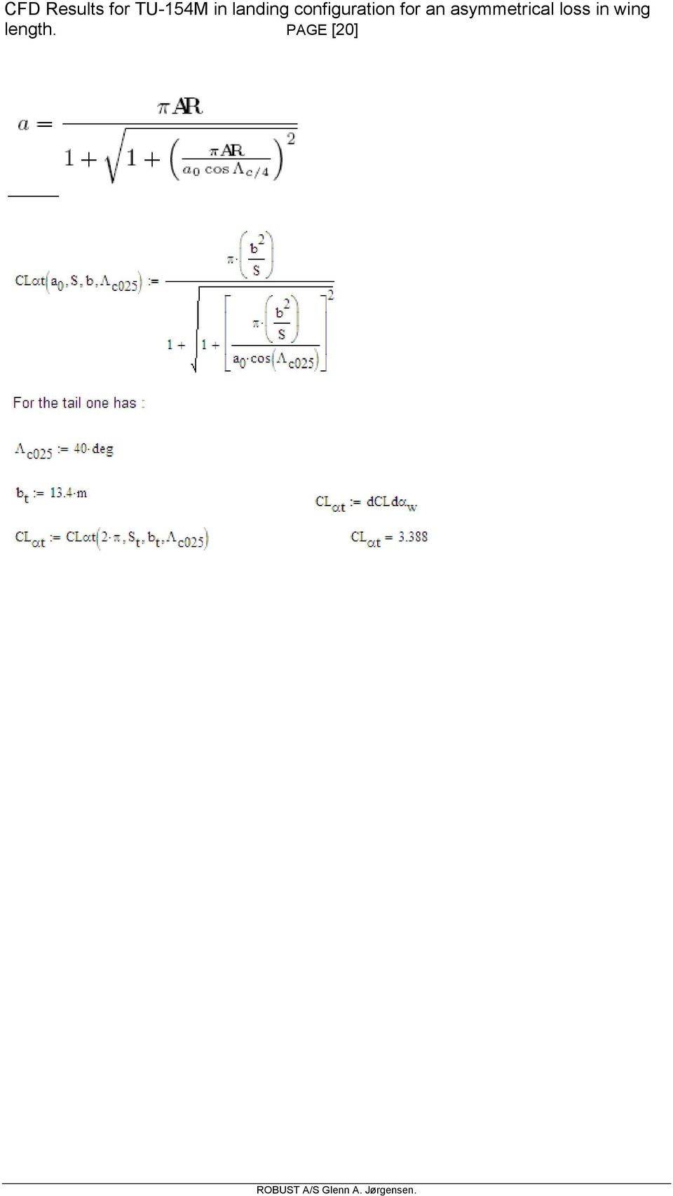
20 length. PAGE [20]
21 length. PAGE [21] APPENDIX 3. Addition of Twist and Correction of Flap Angle. Where Cfb x is the local coefficient of lift for the broken wing at α = x Cfb_36 x is local coefficient of lift for the broken wing and flap angle = 36 at α = x Cf_36t x as above including twist at α = x β is the twist vector as defined in [3]. See Fig. 16. eff(f) is the flap efficiency function. See below.
22 length. PAGE [22] Data from [2] show the shift in α0 as a function of the flap angles 28 and 45. These are used to interpolate to the value at flap angle of 36 taking the small non-linearity into account. The flap efficiency E f is defined as Where δ 3 = δ is the flap angle and α 0 is the angle of attack for zero lift as listed in the table above. E f (δ) = *δ *δ This functionality takes the small non-linearity of the shift in α 0 as a function of flap angle into account. From this the effect of change of flap from 28 to 36 can be found as: E f (36 )/ E f (28 ) = 1.244
23 length. PAGE [23] APPENDIX 4. Correction of wing tip length. The function r = Cfb/Cf shows how the local lift coefficients are influenced by the loss of wing length for α=0 to α=12. When evaluating the local lift coefficients for at lost wing tip of ΔL = 5.54 m the same dependency is used, but now stretched to the new position.
24 length. PAGE [24] APPENDIX 5. Tu 154 wing aerodynamics ([1]).
25 length. PAGE [25]
26 length. PAGE [26]
27 length. PAGE [27]
28 length. PAGE [28]
29 length. PAGE [29]
30 length. PAGE [30]
31 length. PAGE [31]
32 length. PAGE [32]
33 length. PAGE [33]
34 length. PAGE [34] APPENDIX 6. Simple Area Method.
35 length. PAGE [35]
36 length. PAGE [36] The loss by CFD/CFD (upper fig) and by CFD/Area (lower fig). The part a is the loss carried by the lost wing area, and the part b is the loss associated with the change in the local lift coefficients of the remaining wing area. ArmCFD < ArmArea and FCFD > FArea, but it turns out that M CFD = Arm CFD *F CFD M Area = Arm Area *F Area
37 length. PAGE [37] The change in C*CL(y) for α gk = 0, 4, 8 and 12. The integral of dc*cl(y) equals the loss in lifting force, the aerodynamic centre, Yc, is found as: Where cx(y) : is the chord length CL(y) : is the local lifting coefficient function of the intact wing at α of interest CLb(y) : is the local lifting coefficient function of the broken wing at α of interest y : is the span coordinate
38 length. PAGE [38] REFERENCES. [1] Tu 154 wing aerodynamics. Data produced for the Millera Kommission. Not Yet published (according to the author). (Included in appendix 5). Data sent to the author of this report by G. Kowaleczko oct [2] В. П. Бехтир, В. М. Ржевский, В. Г. Ципенко, ПРАКТИЧЕСКАЯ АЭРОДИНАМИКА САМОЛЕТА Ту-154М, page 19. [3] Аэродинамика самолета Ту-154Б, Moskva т.и.лигум, с.ю.скрилниченко, а.в.шишмарев [4] Introduction to Aircraft Stability and Control Course Notes for M&AE 5070 David A. Caughey. Sibley School of Mechanical & Aerospace Engineering Cornell University Ithaca, New York [5] Span Efficiencies of Wings at Low Reynolds Numbers, G. R. Spedding and J. McArthur University of Southern California, Los Angeles, Los Angeles California [6] REKONSTRUKCJA OSTATNIEJ FAZY LOTU SAMOLOTU TU-154M. Prof. Dr hab. inż. Grzegorz Kowaleczko, 31-dec (Published ). [7] CALCULATION OF THE FINAL SECONDS OF FLIGHT OF P101, Glenn Arthur Jørgensen, [8] From Instytut Techniki Lotniczej i Mechaniki Stosowanej. Polytechnika Warszawska.
The aerodynamic center
 The aerodynamic center In this chapter, we re going to focus on the aerodynamic center, and its effect on the moment coefficient C m. 1 Force and moment coefficients 1.1 Aerodynamic forces Let s investigate
NACA Nomenclature NACA 2421. NACA Airfoils. Definitions: Airfoil Geometry
 0.40 m 0.21 m 0.02 m NACA Airfoils 6-Feb-08 AE 315 Lesson 10: Airfoil nomenclature and properties 1 Definitions: Airfoil Geometry z Mean camber line Chord line x Chord x=0 x=c Leading edge Trailing edge
Aerodynamic Design Optimization Discussion Group Case 4: Single- and multi-point optimization problems based on the CRM wing
 Aerodynamic Design Optimization Discussion Group Case 4: Single- and multi-point optimization problems based on the CRM wing Lana Osusky, Howard Buckley, and David W. Zingg University of Toronto Institute
High-Lift Systems. High Lift Systems -- Introduction. Flap Geometry. Outline of this Chapter
 High-Lift Systems Outline of this Chapter The chapter is divided into four sections. The introduction describes the motivation for high lift systems, and the basic concepts underlying flap and slat systems.
Design and Structural Analysis of the Ribs and Spars of Swept Back Wing
 Design and Structural Analysis of the Ribs and Spars of Swept Back Wing Mohamed Hamdan A 1, Nithiyakalyani S 2 1,2 Assistant Professor, Aeronautical Engineering & Srinivasan Engineering College, Perambalur,
A NUMERICAL METHOD TO PREDICT THE LIFT OF AIRCRAFT WINGS AT STALL CONDITIONS
 Braz. Soc. of Mechanical Sciences and Engineering -- ABCM, Rio de Janeiro, Brazil, Nov. 29 -- Dec. 3, 24 A NUMERICAL METHOD TO PREDICT THE LIFT OF AIRCRAFT WINGS AT STALL CONDITIONS Marcos A. Ortega ITA
Lift and Drag on an Airfoil ME 123: Mechanical Engineering Laboratory II: Fluids
 Lift and Drag on an Airfoil ME 123: Mechanical Engineering Laboratory II: Fluids Dr. J. M. Meyers Dr. D. G. Fletcher Dr. Y. Dubief 1. Introduction In this lab the characteristics of airfoil lift, drag,
Lab 8 Notes Basic Aircraft Design Rules 6 Apr 06
 Lab 8 Notes Basic Aircraft Design Rules 6 Apr 06 Nomenclature x, y longitudinal, spanwise positions S reference area (wing area) b wing span c average wing chord ( = S/b ) AR wing aspect ratio C L lift
Wing Design: Major Decisions. Wing Area / Wing Loading Span / Aspect Ratio Planform Shape Airfoils Flaps and Other High Lift Devices Twist
 Wing Design: Major Decisions Wing Area / Wing Loading Span / Aspect Ratio Planform Shape Airfoils Flaps and Other High Lift Devices Twist Wing Design Parameters First Level Span Area Thickness Detail Design
APPENDIX 3-B Airplane Upset Recovery Briefing. Briefing. Figure 3-B.1
 APPENDIX 3-B Airplane Upset Recovery Briefing Industry Solutions for Large Swept-Wing Turbofan Airplanes Typically Seating More Than 100 Passengers Briefing Figure 3-B.1 Revision 1_August 2004 Airplane
A. Hyll and V. Horák * Department of Mechanical Engineering, Faculty of Military Technology, University of Defence, Brno, Czech Republic
 AiMT Advances in Military Technology Vol. 8, No. 1, June 2013 Aerodynamic Characteristics of Multi-Element Iced Airfoil CFD Simulation A. Hyll and V. Horák * Department of Mechanical Engineering, Faculty
Introduction to Aircraft Stability and Control Course Notes for M&AE 5070
 Introduction to Aircraft Stability and Control Course Notes for M&AE 57 David A. Caughey Sibley School of Mechanical & Aerospace Engineering Cornell University Ithaca, New York 14853-751 211 2 Contents
Numerical Approach Aspects for the Investigation of the Longitudinal Static Stability of a Transport Aircraft with Circulation Control
 Numerical Approach Aspects for the Investigation of the Longitudinal Static Stability of a Transport Aircraft with Circulation Control Dennis Keller Abstract The aim of the investigation is to gain more
Chapter 6 Lateral static stability and control - 3 Lecture 21 Topics
 Chapter 6 Lateral static stability and control - 3 Lecture 21 Topics 6.11 General discussions on control surface 6.11.1 Aerodynamic balancing 6.11.2 Set back hinge or over hang balance 6.11.3 Horn balanace
NACA 2415- FINDING LIFT COEFFICIENT USING CFD, THEORETICAL AND JAVAFOIL
 NACA 2415- FINDING LIFT COEFFICIENT USING CFD, THEORETICAL AND JAVAFOIL Sarfaraj Nawaz Shaha 1, M. Sadiq A. Pachapuri 2 1 P.G. Student, MTech Design Engineering, KLE Dr. M S Sheshgiri College of Engineering
Aerodynamic Department Institute of Aviation. Adam Dziubiński CFD group FLUENT
 Adam Dziubiński CFD group IoA FLUENT Content Fluent CFD software 1. Short description of main features of Fluent 2. Examples of usage in CESAR Analysis of flow around an airfoil with a flap: VZLU + ILL4xx
Light Aircraft Design
 New: Sport Pilot (LSA) The Light Aircraft Design Computer Program Package - based on MS-Excelapplication was now extented with the new Sport Pilots (LSA) loads module, which includes compliance for the
Flightlab Ground School 5. Longitudinal Static Stability
 Flightlab Ground School 5. Longitudinal Static Stability Copyright Flight Emergency & Advanced Maneuvers Training, Inc. dba Flightlab, 2009. All rights reserved. For Training Purposes Only Longitudinal
AE 430 - Stability and Control of Aerospace Vehicles
 AE 430 - Stability and Control of Aerospace Vehicles Atmospheric Flight Mechanics 1 Atmospheric Flight Mechanics Performance Performance characteristics (range, endurance, rate of climb, takeoff and landing
Thin Airfoil Theory. Charles R. O Neill School of Mechanical and Aerospace Engineering Oklahoma State University Stillwater, OK 74078
 13 Thin Airfoil Theory Charles R. O Neill School of Mechanical and Aerospace Engineering Oklahoma State University Stillwater, OK 7478 Project One in MAE 3253 Applied Aerodynamics and Performance March
Airplane/Glider Design Guidelines and Design Analysis Program
 Airplane/Glider Design Guidelines and Design Analysis Program Ever have the urge to design your own plane but didn t feel secure enough with your usual TLAR (that looks about right) methods to invest all
Application of CFD Simulation in the Design of a Parabolic Winglet on NACA 2412
 , July 2-4, 2014, London, U.K. Application of CFD Simulation in the Design of a Parabolic Winglet on NACA 2412 Arvind Prabhakar, Ayush Ohri Abstract Winglets are angled extensions or vertical projections
XFlow CFD results for the 1st AIAA High Lift Prediction Workshop
 XFlow CFD results for the 1st AIAA High Lift Prediction Workshop David M. Holman, Dr. Monica Mier-Torrecilla, Ruddy Brionnaud Next Limit Technologies, Spain THEME Computational Fluid Dynamics KEYWORDS
HALE UAV: AeroVironment Pathfinder
 HALE UAV: AeroVironment Pathfinder Aerodynamic and Stability Analysis Case Study: Planform Optimization Desta Alemayehu Elizabeth Eaton Imraan Faruque Photo courtesy NASA Dryden Photo Gallery 1 Pathfinder
Practice Problems on Boundary Layers. Answer(s): D = 107 N D = 152 N. C. Wassgren, Purdue University Page 1 of 17 Last Updated: 2010 Nov 22
: D = 107 N D = 152 N. C. Wassgren, Purdue University Page 1 of 17 Last Updated: 2010 Nov 22") BL_01 A thin flat plate 55 by 110 cm is immersed in a 6 m/s stream of SAE 10 oil at 20 C. Compute the total skin friction drag if the stream is parallel to (a) the long side and (b) the short side. D =
BL_01 A thin flat plate 55 by 110 cm is immersed in a 6 m/s stream of SAE 10 oil at 20 C. Compute the total skin friction drag if the stream is parallel to (a) the long side and (b) the short side. D =
From A to F: The F/A-18 Hornet
 From A to F: The F/A-18 Hornet F/A-18 Breaking the Sound Barrier. Source: www.boeing.com By: Kevin Waclawicz 4/28/00 Some History On January 6, 1972, the USAF issued a request for proposals for a lightweight
CFD simulations of flow over NASA Trap Wing Model
 CFD simulations of flow over NASA Trap Wing Model Andy Luo Swift Engineering Pravin Peddiraju, Vangelis Skaperdas BETA CAE Systems Introduction A cooperative study was undertaken by BETA and Swift Engineering
High-Speed Demonstration of Natural Laminar Flow Wing & Load Control for Future Regional Aircraft through innovative Wind Tunnel Model
 High-Speed Demonstration of Natural Laminar Flow Wing & Load Control for Future Regional Aircraft through innovative Wind Tunnel Model Project organization The project tackles the CfP JTI-CS-2012-1-GRA-02-019
Flap Optimization for Take-off and Landing
 Proceedings of the 10th Brazilian Congress of Thermal Sciences and Engineering -- ENCIT 2004 Braz. Soc. of Mechanical Sciences and Engineering -- ABCM, Rio de Janeiro, Brazil, Nov. 29 -- Dec. 03, 2004
QUT Digital Repository: http://eprints.qut.edu.au/
 QUT Digital Repository: http://eprints.qut.edu.au/ El-Atm, Billy and Kelson, Neil A. and Gudimetla, Prasad V. (2008) A finite element analysis of the hydrodynamic performance of 3- and 4-Fin surfboard
Aerospace Engineering 3521: Flight Dynamics. Prof. Eric Feron Homework 6 due October 20, 2014
 Aerospace Engineering 3521: Flight Dynamics Prof. Eric Feron Homework 6 due October 20, 2014 1 Problem 1: Lateral-directional stability of Navion With the help of Chapter 2 of Nelson s textbook, we established
CFD ANALYSIS OF RAE 2822 SUPERCRITICAL AIRFOIL AT TRANSONIC MACH SPEEDS
 CFD ANALYSIS OF RAE 2822 SUPERCRITICAL AIRFOIL AT TRANSONIC MACH SPEEDS K.Harish Kumar 1, CH.Kiran Kumar 2, T.Naveen Kumar 3 1 M.Tech Thermal Engineering, Sanketika Institute of Technology & Management,
parts of an airplane Getting on an Airplane BOX Museum Aeronautics Research Mission Directorate in a Series
 National Aeronautics and Space Administration GRADES K-2 Aeronautics Research Mission Directorate Museum in a BOX Series www.nasa.gov parts of an airplane Getting on an Airplane MUSEUM IN A BOX Getting
Toward Zero Sonic-Boom and High Efficiency. Supersonic Bi-Directional Flying Wing
 AIAA Paper 2010-1013 Toward Zero Sonic-Boom and High Efficiency Supersonic Flight: A Novel Concept of Supersonic Bi-Directional Flying Wing Gecheng Zha, Hongsik Im, Daniel Espinal University of Miami Dept.
NACA airfoil geometrical construction
 The NACA airfoil series The early NACA airfoil series, the 4-digit, 5-digit, and modified 4-/5-digit, were generated using analytical equations that describe the camber (curvature) of the mean-line (geometric
TopSky DLG Installation Manual
 TopSky DLG Installation Manual Attention: Because after the compound materials solidify, there will be ammonia iris on the surface, which affect the bonding strength afterwards. Please polish with sandpaper
Theory of turbo machinery / Turbomaskinernas teori. Chapter 3
 Theory of turbo machinery / Turbomaskinernas teori Chapter 3 D cascades Let us first understand the facts and then we may seek the causes. (Aristotle) D cascades High hub-tip ratio (of radii) negligible
Computational Aerodynamic Analysis on Store Separation from Aircraft using Pylon
 International Journal of Engineering Science Invention (IJESI) ISSN (Online): 2319 6734, ISSN (Print): 2319 6726 www.ijesi.org ǁ PP.27-31 Computational Aerodynamic Analysis on Store Separation from Aircraft
Aerodynamics of Flight
 Chapter 2 Aerodynamics of Flight Introduction This chapter presents aerodynamic fundamentals and principles as they apply to helicopters. The content relates to flight operations and performance of normal
Simulation at Aeronautics Test Facilities A University Perspective Helen L. Reed, Ph.D., P.E. ASEB meeting, Irvine CA 15 October 2014 1500-1640
 Simulation at Aeronautics Test A University Perspective Helen L. Reed, Ph.D., P.E. ASEB meeting, Irvine CA 15 October 2014 1500-1640 Questions How has the ability to do increasingly accurate modeling and
A COMPARISON BETWEEN THE AERODYNAMIC PRESSURE FACTORING AND THE AERODYNAMIC DERIVATIVES FACTORING METHODS FOR THE DOUBLET LATTICE PROGRAM
 A COMPARISON BETWEEN THE AERODYNAMIC PRESSURE FACTORING AND THE AERODYNAMIC DERIVATIVES FACTORING METHODS FOR THE DOUBLET LATTICE PROGRAM Paper Reference No. 1-1 by Emil Suciu* esuciu@yahoo.com ABSTRACT
Comparison between OpenFOAM CFD & BEM theory for variable speed variable pitch HAWT
 ITM Web of Conferences 2, 05001 (2014) DOI: 10.1051/itmconf/20140205001 C Owned by the authors, published by EDP Sciences, 2014 Comparison between OpenFOAM CFD & BEM theory for variable speed variable
CFD Analysis of Civil Transport Aircraft
 IJSRD - International Journal for Scientific Research & Development Vol. 3, Issue 06, 2015 ISSN (online): 2321-0613 CFD Analysis of Civil Transport Aircraft Parthsarthi A Kulkarni 1 Dr. Pravin V Honguntikar
Aerodynamics of Rotating Discs
 Proceedings of ICFD 10: Tenth International Congress of FluidofDynamics Proceedings ICFD 10: December 16-19, 2010, Stella Di MareTenth Sea Club Hotel, Ain Soukhna, Egypt International Congress of Red FluidSea,
ESTIMATING R/C MODEL AERODYNAMICS AND PERFORMANCE
 ESTIMATING R/C MODEL AERODYNAMICS AND PERFORMANCE Adapted from Dr. Leland M. Nicolai s Write-up (Technical Fellow, Lockheed Martin Aeronautical Company) by Dr. Murat Vural (Illinois Institute of Technology)
ENHANCEMENT OF AERODYNAMIC PERFORMANCE OF A FORMULA-1 RACE CAR USING ADD-ON DEVICES B. N. Devaiah 1, S. Umesh 2
 ENHANCEMENT OF AERODYNAMIC PERFORMANCE OF A FORMULA-1 RACE CAR USING ADD-ON DEVICES B. N. Devaiah 1, S. Umesh 2 1- M. Sc. [Engg.] Student, 2- Asst. Professor Automotive and Aeronautical Engineering Department,
Design and Analysis of Spiroid Winglet
 Design and Analysis of Spiroid Winglet W.GiftonKoil Raj 1, T.AmalSeba Thomas 2 PG Scholar, Dept of Aeronautical Engineering, Hindustan Institute of Technology and Science, Chennai, India 1 Assistant Professor,
Fundamentals of Airplane Flight Mechanics
 Fundamentals of Airplane Flight Mechanics David G. Hull Fundamentals of Airplane Flight Mechanics With 125 Figures and 25 Tables 123 David G. Hull The University of Texas at Austin Aerospace Engineering
SIX DEGREE-OF-FREEDOM MODELING OF AN UNINHABITED AERIAL VEHICLE. A thesis presented to. the faculty of
 SIX DEGREE-OF-FREEDOM MODELING OF AN UNINHABITED AERIAL VEHICLE A thesis presented to the faculty of the Russ College of Engineering and Technology of Ohio University In partial fulfillment of the requirement
Model Aircraft Design
 Model Aircraft Design A teaching series for secondary students Contents Introduction Learning Module 1 How do planes fly? Learning Module 2 How do pilots control planes? Learning Module 3 What will my
DESIGN OF THE MODERN FAMILY OF HELICOPTER AIRFOILS 51
 DESIGN OF THE MODERN FAMILY OF HELICOPTER AIRFOILS Wojciech KANIA, Wieńczysław STALEWSKI, Bogumiła ZWIERZCHOWSKA Institute of Aviation Summary The paper presents results of numerical design and experimental
PARAMETRIC INVESTIGATION OF A HIGH-LIFT AIRFOIL AT HIGH REYNOLDS NUMBERS. John C. Lin* NASA Langley Research Center, Hampton, VA 23681-0001.
 PARAMETRIC INVESTIGATION OF A HIGH-LIFT AIRFOIL AT HIGH REYNOLDS NUMBERS John C. Lin* NASA Langley Research Center, Hampton, VA 23681-0001 and Chet J. Dominik McDonnell Douglas Aerospace, Long Beach, CA
CAMRAD II COMPREHENSIVE ANALYTICAL MODEL OF ROTORCRAFT AERODYNAMICS AND DYNAMICS
 CAMRAD II COMPREHENSIVE ANALYTICAL MODEL OF ROTORCRAFT AERODYNAMICS AND DYNAMICS 1 CAMRAD II IS AN AEROMECHANICAL ANALYSIS OF HELICOPTERS AND ROTORCRAFT INCORPORATING ADVANCED TECHNOLOGY multibody dynamics
The Influence of Aerodynamics on the Design of High-Performance Road Vehicles
 The Influence of Aerodynamics on the Design of High-Performance Road Vehicles Guido Buresti Department of Aerospace Engineering University of Pisa (Italy) 1 CONTENTS ELEMENTS OF AERODYNAMICS AERODYNAMICS
GLIDING BIRDS: REDUCTION OF INDUCED DRAG BY WING TIP SLOTS BETWEEN THE PRIMARY FEATHERS
 J. exp. Biol. 180, 285-310 (1993) Printed in Great Britain The Company of Biologists Limited 1993 285 GLIDING BIRDS: REDUCTION OF INDUCED DRAG BY WING TIP SLOTS BETWEEN THE PRIMARY FEATHERS VANCE A. TUCKER
Computational Fluid Dynamics Investigation of Two Surfboard Fin Configurations.
 Computational Fluid Dynamics Investigation of Two Surfboard Fin Configurations. By: Anthony Livanos (10408690) Supervisor: Dr Philippa O Neil Faculty of Engineering University of Western Australia For
Cessna Skyhawk II / 100. Performance Assessment
 Cessna Skyhawk II / 100 Performance Assessment Prepared by John McIver B.Eng.(Aero) Temporal Images 23rd January 2003 http://www.temporal.com.au Cessna Skyhawk II/100 (172) Performance Assessment 1. Introduction
Largest Fixed-Aspect, Axis-Aligned Rectangle
 Largest Fixed-Aspect, Axis-Aligned Rectangle David Eberly Geometric Tools, LLC http://www.geometrictools.com/ Copyright c 1998-2016. All Rights Reserved. Created: February 21, 2004 Last Modified: February
Circulation Control NASA activities
 National Aeronautics and Space Administration Circulation Control NASA activities Dr. Gregory S. Jones Dr. William E. Millholen II Research Engineers NASA Langley Research Center Active High Lift and Impact
Highly Optimizable Laminar Flow Control Devices
 Highly Optimizable Laminar Flow Control Devices Johan Valentin Krier 1, Triyantono Sucipto 1 1 IBK-Ingenieurbuero, Rehdorfer Str. 4, D-90431 Nuremberg, Germany E-mail: Johann.Krier@ibk-tech.de, Triyantono.Sucipto@ibk-tech.de
THE CFD SIMULATION OF THE FLOW AROUND THE AIRCRAFT USING OPENFOAM AND ANSA
 THE CFD SIMULATION OF THE FLOW AROUND THE AIRCRAFT USING OPENFOAM AND ANSA Adam Kosík Evektor s.r.o., Czech Republic KEYWORDS CFD simulation, mesh generation, OpenFOAM, ANSA ABSTRACT In this paper we describe
AERODYNAMIC ANALYSIS OF BLADE 1.5 KW OF DUAL ROTOR HORIZONTAL AXIS WIND TURBINE
 AERODYNAMIC ANALYSIS OF BLADE 1.5 KW OF DUAL ROTOR HORIZONTAL AXIS WIND TURBINE HITENDRA KURMI Research scholar, School of Energy and Environmental Managment,UTD, RGPV Bhopal,MP,INDIA htr.ptl@gmail.com
Section 4: The Basics of Satellite Orbits
 Section 4: The Basics of Satellite Orbits MOTION IN SPACE VS. MOTION IN THE ATMOSPHERE The motion of objects in the atmosphere differs in three important ways from the motion of objects in space. First,
AUTOMOTIVE COMPUTATIONAL FLUID DYNAMICS SIMULATION OF A CAR USING ANSYS
 International Journal of Mechanical Engineering and Technology (IJMET) Volume 7, Issue 2, March-April 2016, pp. 91 104, Article ID: IJMET_07_02_013 Available online at http://www.iaeme.com/ijmet/issues.asp?jtype=ijmet&vtype=7&itype=2
Knowledge Based Aerodynamic Optimization
 4th SST CFD Workshop Tokyo, 12-13 Oct 26 Knowledge Based Aerodynamic Optimization Helmut Sobieczky DLR German Aerospace Center Bunsenstr. 1, 3773 Göttingen, Germany e-mail: helmut.sobieczky@dlr.de... internet:
MacroFlo Opening Types User Guide <Virtual Environment> 6.0
 MacroFlo Opening Types User Guide 6.0 Page 1 of 18 Contents 1. Introduction...4 2. What Are Opening Types?...5 3. MacroFlo Opening Types Manager Interface...5 3.1. Add... 5 3.2. Reference
CFD Lab Department of Engineering The University of Liverpool
 Development of a CFD Method for Aerodynamic Analysis of Large Diameter Horizontal Axis wind turbines S. Gomez-Iradi, G.N. Barakos and X. Munduate 2007 joint meeting of IEA Annex 11 and Annex 20 Risø National
Numerical Simulation of the External Flow Field. Around a Bluff Car*
 Numerical Simulation of the External Flow Field Around a Bluff Car* Sun Yongling, Wu Guangqiang, Xieshuo Automotive Engineering Department Shanghai Tongji University Shanghai, China E-mail: wuqjuhyk@online.sh.cn
INJECTION MOLDING COOLING TIME REDUCTION AND THERMAL STRESS ANALYSIS
 INJECTION MOLDING COOLING TIME REDUCTION AND THERMAL STRESS ANALYSIS Tom Kimerling University of Massachusetts, Amherst MIE 605 Finite Element Analysis Spring 2002 ABSTRACT A FEA transient thermal structural
Aeronautical Testing Service, Inc. 18820 59th DR NE Arlington, WA 98223 USA. CFD and Wind Tunnel Testing: Complimentary Methods for Aircraft Design
 Aeronautical Testing Service, Inc. 18820 59th DR NE Arlington, WA 98223 USA CFD and Wind Tunnel Testing: Complimentary Methods for Aircraft Design Background Introduction ATS Company Background New and
Reynolds Averaged Navier-Stokes Analysis for Civil Transport Aircraft using Structured and Unstructured grids
 14 th Annual CFD Symposium 10 th 11 th August 2012, Bangalore Reynolds Averaged Navier-Stokes Analysis for Civil Transport Aircraft using Structured and Unstructured grids Vishal S. Shirbhate CTFD Division,
CFD ANALYSiS OF ExTERNAL ARmOUR influence ON A HELiCOPTER AERODYNAmiC CHARACTERiSTiCS
 PRACE instytutu LOTNiCTWA ISSN 0509-6669 218, s. 20-27, Warszawa 2011 CFD ANALYSiS OF ExTERNAL ARmOUR influence ON A HELiCOPTER AERODYNAmiC CHARACTERiSTiCS AdAm dziubiński, katarzyna GrzeGorczyk, Jerzy
Project Flight Controls
 Hogeschool van Amsterdam Amsterdamse Hogeschool voor techniek Aviation studies Project Flight Controls ALA Group: 2A1Q Jelle van Eijk Sander Groenendijk Robbin Habekotte Rick de Hoop Wiecher de Klein Jasper
Rotation: Moment of Inertia and Torque
 Rotation: Moment of Inertia and Torque Every time we push a door open or tighten a bolt using a wrench, we apply a force that results in a rotational motion about a fixed axis. Through experience we learn
CFD Calculations of S809 Aerodynamic Characteristics 1
 Walter P. Wolfe Engineering Sciences Center Sandia National Laboratories Albuquerque, NM 87185-0836 Stuart S. Ochs Aerospace Engineering Department Iowa State University Ames, IA 50011 CFD Calculations
Aerodynamic design and cross-country flight performance analysis of Diana-2 sailplane
 Aerodynamic design and cross-country flight performance analysis of Diana-2 sailplane Krzysztof Kubrynski Warsaw University of Technology, Institute of Aeronautics and Applied Mechanics Warsaw, Poland,
Behavioral Animation Simulation of Flocking Birds
 Behavioral Animation Simulation of Flocking Birds Autonomous characters determine their actions Simulating the paths of individuals in: flocks of birds, schools of fish, herds of animals crowd scenes 1.
AIR FORCE INSTITUTE OF TECHNOLOGY
 CFD Analysis of a T-38 Wing Fence THESIS Daniel Allan Solfelt, Ensign, USN AFIT/GAE/ENY/07-J19 DEPARTMENT OF THE AIR FORCE AIR UNIVERSITY AIR FORCE INSTITUTE OF TECHNOLOGY Wright-Patterson Air Force Base,
Models of Lift and Drag Coefficients of Stalled and Unstalled Airfoils in Wind Turbines and Wind Tunnels
 NASA/CR 2008-215434 Models of Lift and Drag Coefficients of Stalled and Unstalled Airfoils in Wind Turbines and Wind Tunnels David A. Spera Jacobs Technology, Inc., Cleveland, Ohio An errata was added
Using CEASIOM-SUMO RapidMeshing in Computational Study of. Asymmetric Aircraft Design
 Using CEASIOM-SUMO RapidMeshing in Computational Study of Asymmetric Aircraft Design Mengmeng Zhang, Arthur Rizzi Royal Institute of Technology (KTH), Stockholm, Sweden & D. Raymer Conceptual Research
CFD Simulations and Wind Tunnel Experiments of a Generic Split-Canard Air-to-Air Missile at High Angles of Attack in Turbulent Subsonic Flow
 AIAA Atmospheric Flight Mechanics Conference 08-11 August 2011, Portland, Oregon AIAA 2011-6335 CFD Simulations and Wind Tunnel Experiments of a Generic Split-Canard Air-to-Air Missile at High Angles of
Relevance of Modern Optimization Methods in Turbo Machinery Applications
 Relevance of Modern Optimization Methods in Turbo Machinery Applications - From Analytical Models via Three Dimensional Multidisciplinary Approaches to the Optimization of a Wind Turbine - Prof. Dr. Ing.
Dipl. Ing. Falk Pätzold Technische Universität Braunschweig, Institut für Flugführung February 21 st 2014
 1/14 Results of Flight Performance Determination of the Lak 17a FES (S5 3117) using the comparison flight method in Aalen Heidenheim Elchingen, August 20th and 21st 2012 Dipl. Ing. Falk Pätzold Technische
How do sails work? Article by Paul Bogataj
 How do sails work? Article by Paul Bogataj Sails are wings that use the wind to generate a force to move a boat. The following explanation of how this occurs can help understand how to maximize the performance
Engine Yaw Augmentation for Hybrid-Wing-Body Aircraft via Optimal Control Allocation Techniques
 AIAA Guidance, Navigation, and Control Conference 08-11 August 2011, Portland, Oregon AIAA 2011-6253 Engine Yaw Augmentation for Hybrid-Wing-Body Aircraft via Optimal Control Allocation Techniques Brian
Solving Simultaneous Equations and Matrices
 Solving Simultaneous Equations and Matrices The following represents a systematic investigation for the steps used to solve two simultaneous linear equations in two unknowns. The motivation for considering
The Avian Skeleton. Avian Flight. The Pelvic Girdle. Skeletal Strength. The Pelvic Girdle
 Flight is the central avian adaptation Birds can fly at great speeds, for extended distances and time periods, can soar for days, and hover, fly upside down, and backwards Adaptations for flight are integrated
APP Aircraft Performance Program Demo Notes Using Cessna 172 as an Example
 APP Aircraft Performance Program Demo Notes Using Cessna 172 as an Example Prepared by DARcorporation 1. Program Layout & Organization APP Consists of 8 Modules, 5 Input Modules and 2 Calculation Modules.
Summary of Aerodynamics A Formulas
 Summary of Aerodynamics A Formulas 1 Relations between height, pressure, density and temperature 1.1 Definitions g = Gravitational acceleration at a certain altitude (g 0 = 9.81m/s 2 ) (m/s 2 ) r = Earth
CFD Study on the Diffuser of a Formula 3 Racecar
 CFD Study on the Diffuser of a Formula 3 Racecar Kevin M. Peddie, Luis F. Gonzalez School of Aerospace, Mechanical and Mechatronic Engineering University of Sydney ABSTRACT The primary goal of the paper
Copyright 2011 Casa Software Ltd. www.casaxps.com. Centre of Mass
 Centre of Mass A central theme in mathematical modelling is that of reducing complex problems to simpler, and hopefully, equivalent problems for which mathematical analysis is possible. The concept of
Lecture L29-3D Rigid Body Dynamics
 J. Peraire, S. Widnall 16.07 Dynamics Fall 2009 Version 2.0 Lecture L29-3D Rigid Body Dynamics 3D Rigid Body Dynamics: Euler Angles The difficulty of describing the positions of the body-fixed axis of
Visualization and Data Mining of Pareto Solutions Using Self-Organizing Map
 Visualization and Data Mining of Solutions Using Self-Organizing Map Shigeru Obayashi and Daisuke Sasaki Institute of Fluid Science, Tohoku University, Sendai, 980-8577 JAPAN obayashi@ieee.org, sasaki@reynolds.ifs.tohoku.ac.jp
(1) 2 TEST SETUP. Table 1 Summary of models used for calculating roughness parameters Model Published z 0 / H d/h
 2 TEST SETUP. Table 1 Summary of models used for calculating roughness parameters Model Published z 0 / H d/h") Estimation of Surface Roughness using CFD Simulation Daniel Abdi a, Girma T. Bitsuamlak b a Research Assistant, Department of Civil and Environmental Engineering, FIU, Miami, FL, USA, dabdi001@fiu.edu
Estimation of Surface Roughness using CFD Simulation Daniel Abdi a, Girma T. Bitsuamlak b a Research Assistant, Department of Civil and Environmental Engineering, FIU, Miami, FL, USA, dabdi001@fiu.edu
Backwater Rise and Drag Characteristics of Bridge Piers under Subcritical
 European Water 36: 7-35, 11. 11 E.W. Publications Backwater Rise and Drag Characteristics of Bridge Piers under Subcritical Flow Conditions C.R. Suribabu *, R.M. Sabarish, R. Narasimhan and A.R. Chandhru
LOCKHEED GEORGIA LOWSPEED WIND TUNNEL HONDA CIVIC HATCHBACK AIRTAB(R) MODIFICATION RESULTS
 MODIFICATION RESULTS") LOCKHEED GEORGIA LOWSPEED WIND TUNNEL HONDA CIVIC HATCHBACK AIRTAB(R) MODIFICATION RESULTS Executive Summary: This report shows conclusively that the Airtab product reduced aerodynamic drag forces at the
LOCKHEED GEORGIA LOWSPEED WIND TUNNEL HONDA CIVIC HATCHBACK AIRTAB(R) MODIFICATION RESULTS Executive Summary: This report shows conclusively that the Airtab product reduced aerodynamic drag forces at the
Natural Convection. Buoyancy force
 Natural Convection In natural convection, the fluid motion occurs by natural means such as buoyancy. Since the fluid velocity associated with natural convection is relatively low, the heat transfer coefficient
Removing chips is a method for producing plastic threads of small diameters and high batches, which cause frequent failures of thread punches.
 Plastic Threads Technical University of Gabrovo Yordanka Atanasova Threads in plastic products can be produced in three ways: a) by direct moulding with thread punch or die; b) by placing a threaded metal
A CFD Study of Wind Turbine Aerodynamics
 A CFD Study of Wind Turbine Aerodynamics Chris Kaminsky *, Austin Filush *, Paul Kasprzak * and Wael Mokhtar ** Department of Mechanical Engineering Grand Valley State University Grand Rapids, Michigan
The Influence of Aerodynamics on the Design of High-Performance Road Vehicles
 The Influence of Aerodynamics on the Design of High-Performance Road Vehicles Guido Buresti Department of Aerospace Engineering University of Pisa (Italy) 1 CONTENTS ELEMENTS OF AERODYNAMICS AERODYNAMICS