TEPZZ 8 8 A_T EP A1 (19) (11) EP A1 (12) EUROPEAN PATENT APPLICATION. (51) Int Cl.: G01N 3/04 ( ) G01N 3/08 (2006.
|
|
|
- Justin Chambers
- 8 years ago
- Views:
Transcription
1 (19) TEPZZ 8 8 A_T (11) EP A1 (12) EUROPEAN PATENT APPLICATION (43) Date of publication: Bulletin 14/0 (1) Int Cl.: G01N 3/04 (06.01) G01N 3/08 (06.01) (21) Application number: (22) Date of filing: (84) Designated Contracting States: AL AT BE BG CH CY CZ DE DK EE ES FI FR GB GR HR HU IE IS IT LI LT LU LV MC MK MT NL NO PL PT RO RS SE SI SK SM TR Designated Extension States: BA ME () Priority: US (71) Applicant: The Boeing Company Chicago, IL (US) (72) Inventor: Kismarton, Max U. Chicago, IL Illinois (US) (74) Representative: Thorniley, Peter et al Kilburn & Strode LLP Red Lion Street London WC1R 4PJ (GB) (4) Apparatus and method for load testing a coupon (7) An apparatus () for load testing a coupon (11) may include a test frame (12) and a pair of spaced apart load balancing assemblies (16a, 16b) connected to the test frame (12), each load balancing assembly (16) of the pair of load balancing assemblies (16a, 16b) including a load leveling mechanism (160) connected to the test frame (12) and a plurality of spaced apart load plates (4), each load plate (4) of the plurality of load plates (4) having a first end (112) pivotably connected to the load leveling mechanism (160) and a second end (118), the second end (118) of each load plat (4)e including a friction holder (4) configured to frictionally engage an end of the coupon (11), wherein at least one load balancing assembly (16) of the pair of load balancing assemblies (16a, 16b) is movable along an axis (X) of movement with respect to an opposed load balancing assembly (16) to communicate a load to the coupon (11). EP A1 Printed by Jouve, 7001 PARIS (FR)
 (74) Representative: Thorniley, Peter et al Kilburn & Strode LLP Red Lion Street London WC1R 4PJ (GB) (4) Apparatus and method for load testing a coupon (7) An")
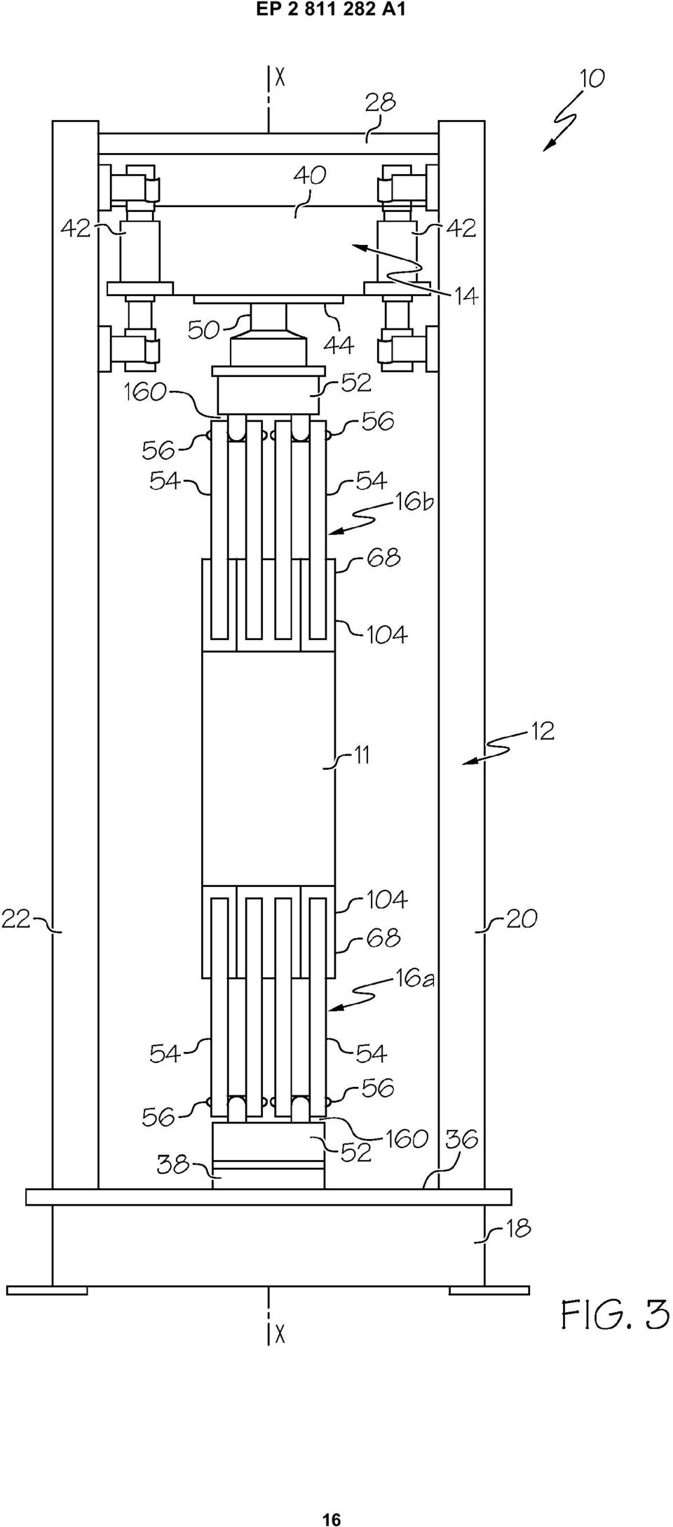
2 1 EP A1 2 Description FIELD [0001] The present disclosure is generally related to material load testing and, more particularly, to an apparatus and method for load testing a coupon of sample material. BACKGROUND [0002] Information related to strength properties and behavior of a material is crucial in component and part design, particularly in the aerospace industry. Typically such information is found through load testing a sample of the material and observing its behavior under various load conditions. For example, a small sample of material, known as a coupon, may be loaded with a tensile load or a compressive load and tested to destruction. [0003] Coupons are typically fabricated to include particular features configured for attachment to a testing jig or machine. For example, several tabs are built on the coupon and holes are drilled through the tabs, which are bolted to the test jig. Once the test is complete, the coupon must be unbolted and removed from the test jig. Thus, the process of testing a new material can be time intensive and costly. For example, the process of fabricating and testing coupons can take between 2 and 6 months. [0004] With the development of new composite materials, the time and cost associated with testing the composites and various configurations of composites can be prohibitive. For example, composite structures have many different combinations of layering will require orders of magnitude more coupon testing. [000] Accordingly, those skilled in the art continue with research and development efforts in the field of material load testing. SUMMARY [0006] In one embodiment, the disclosed apparatus for load testing a coupon may include a test frame and a pair of spaced apart load balancing assemblies connected to the test frame, each load balancing assembly of the pair of load balancing assemblies including a load leveling mechanism connected to the test frame and a plurality of spaced apart load plates, each load plate of the plurality of load plates having a first end pivotably connected to the load leveling mechanism and a second end, the second end of each load plate including a friction holder configured to frictionally engage an end of the coupon, wherein at least one load balancing assembly of the pair of load balancing assemblies is movable along an axis of movement with respect to an opposed load balancing assembly to communicate a load to the coupon. [0007] In another embodiment, the disclosed apparatus for load testing a coupon may include at least one load balancing assembly configured to retain an end of the coupon and communicate an axial load to the coupon upon movement along an axis, the load balancing assembly including a load leveling mechanism and a plurality of spaced apart load plates, each load plate of the plurality of load plates having a first end and a second end, the first end being pivotably connected to the load leveling mechanism and the second end including a friction holder configured to frictionally engage an end of the coupon. [0008] In another embodiment, the disclosed apparatus for load testing a coupon may include at least one load balancing assembly configured to retain an end of the coupon and communicate an axial load to the coupon upon movement along an axis, the load balancing assembly including a load leveling mechanism and a plurality of spaced apart load plates, each load plate of the plurality of load plates having a first end and a second end, the first end being pivotably connected to the load leveling mechanism and the second end including a friction holder configured to frictionally engage an end of the coupon, the friction holder may include adjustably connected to the load plate within an opening, the grip wedge being configured to frictionally engage a substantially planar surface of the coupon, an adjusting mechanism configured to position the grip wedge within the opening, and a connector configured to interconnect the grip wedge and the load plate, the connector being configured to allow movement of the grip wedge with respect to the load plate. [0009] In another embodiment, disclosed is a method for load testing a coupon, the method may include the steps of: (1) providing a test coupon, (2) providing a pair of load balancing assemblies, each load balancing assembly including a load leveling mechanism and a plurality of spaced apart load plates, each load plate of the plurality of load plates including a first end and a second end, the first end being pivotably connected to the load leveling mechanism and the second end including a friction holder, (3) connecting the coupon between the pair of load balancing assemblies, and (4) applying a load to the coupon. [00] Other embodiments of the disclosed apparatus and method for load testing a coupon will become apparent from the following detailed description, the accompanying drawings and the appended claims. BRIEF DESCRIPTION OF THE DRAWINGS [0011] Fig. 1 is a front and side perspective view of one embodiment of the disclosed apparatus for load testing a coupon; Fig. 2 is a side elevational view of the disclosed apparatus for load testing a coupon; 2

3 3 EP A1 4 Fig. 3 is a front elevational view of the disclosed apparatus for load testing a coupon; Fig. 4 is a block diagram illustrating the disclosed apparatus for load testing a coupon; Fig. is a front and side perspective view of one embodiment of the load balancing assembly of the disclosed apparatus for load testing a coupon; Fig. 6 is a side elevational view of the load balancing assembly; Fig. 7 is a front elevational view of the load balancing assembly; Fig. 8 is an enlarged front elevation view of the load balancing assembly; Fig. 9 is a side schematic view of an implementation of the friction holder of the disclosed apparatus for load testing a coupon; Fig. is a side schematic view of another implementation of the friction holder of the disclosed apparatus for load testing a coupon; and Fig. 11 is a flow diagram of the disclosed method for load testing a coupon. DETAILED DESCRIPTION [0012] The following detailed description refers to the accompanying drawings, which illustrate specific embodiments of the disclosure. Other embodiments having different structures and operations do not depart from the scope of the present disclosure. Like reference numerals may refer to the same element or component in the different drawings. [0013] Referring to Figs. 1, the disclosed apparatus for load testing a coupon, generally designated, may include a test frame 12, at least one load assembly 14, and a pair of load balancing assemblies 16a, 16b (generally, a balancing assembly 16). The apparatus may be used in load testing of a coupon 11 to determine the behavior of the material or materials forming the coupon 11 under both compression and tensile loads, particularly under peak load conditions. Each load balancing assembly16 may include a friction holder 4 configured to grip and hold an end of the coupon 11 through friction and a mechanical load leveling mechanism 160 configured to distribute a substantially even load across a width of the coupon 11. [0014] A coupon 11 is a small sample of material that may be tested to destruction to measure the strength properties of the material. As an example, the coupon 11 may be a -inch by 60-inch strip of sample material. However, the coupon 11 may have any geometric shape and dimensions. [001] The pair of load balancing assemblies 16a, 16b may securely retain the coupon 11 at two opposing ends. Each of the load balancing assemblies 16a, 16b may be suitably sized to grip and retain a correspondingly sized coupon 11. The load assembly 14 may deliver a load (e.g., tensile or compression load) to the coupon 11 by moving at least one of the load balancing assemblies 16 along a single axis X (Fig. 2). [0016] The test frame 12 may include a base member 18 configured to support the frame 12 in a generally vertical orientation in relation to a support surface. The base member 18 may have a generally square or rectangular shape, although any other geometric shapes are also contemplated. [0017] A plurality of frame members may be connected to the base member 18 to define the test frame 12. For example, four spaced apart frame members may define a generally rectangular test frame 12. The four frame members may include a first frame member, a second frame member 22, a third frame member 24, and a fourth frame member 26. Each frame member, 22, 24, 26 may include a first end (e.g., lower end) rigidly connected to the base member 18. For example, the first end of each frame member, 22, 24, 26 may be rigidly connected at or near each corner of the base member 18. [0018] A plurality of frame support members may interconnect between the frame members. For example, four frame support members may extend between second ends (e.g., upper ends) of parallel frame members. The four frame support members may include a first frame support member 28, a second frame support member, a third frame support member 32, and a fourth frame support member 34. The first frame support member 28 may interconnect between the second end of the first frame member and the second end of the second frame member 22. The second frame support member may interconnect between the second end of the third frame member 24 and the second end of the fourth frame member 26. The third frame support member 32 may interconnect between the second end of the first frame member and the second end of the third frame member 24. The fourth frame support member 34 may interconnect between the second end of the second frame member 22 and the second end of the fourth frame member 26. [0019] The test frame 12, including the base member 18, the frame members, 22, 24, 26, and the frame support members 28,, 32, 34 may be made from any suitably rigid and durable material. For example, the support base 18 and the frame members, 22, 24, 26 may be made from structural steel tube, steel channel, or steel I-beam. The frame support members 28,, 32, 34 may be made from steel rod or steel tube or channel. In the illustrated embodiment, the members of the test frame 12 may be welded together, however, other embodiments may use other materials and other methods of combining the members of the test frame 12. Alternative- 3

4 EP A1 6 ly, the test frame 12 may be an integral frame body instead of being formed of component members. [00] A first (e.g., lower) load balancing assembly 16a may be connected to the base member 18. For example, the first load balancing assembly 16a may be rigidly connected to a central or middle position of the base member 18. In one implementation of the disclosed apparatus, the base member 18 may include a base platform 36. The base platform 36 may be any suitably rigid and durable member or members suitable for connection of the first load balancing assembly 16a. For example, the base platform 36 may be a steel panel having at least one substantially planar major surface configured to support the first load balancing assembly 16a in fixed position. As another example, the base platform 36 may be a plurality of cross-frame members extending between the corners of the base member 18. [0021] The base member 18 may include a first coupling 38 configured to connect to the first load balancing assembly 16a. For example, the first coupling 38 may be connected about a center or middle of the base platform 36. The first coupling 38 may be any suitable rigid mechanical coupling device, for example, the first coupling 38 may be collar, a sleeve, or a clamp. In this regard, the first coupling 38 may be any type of connection point or attachment point by which the first load balancing assembly 16a may be connected to the base member 18. [0022] Referring to Figs. 2 and 3, the load assembly 14 may include a load platform operably connected to the frame members, 22, 24, 26. The load platform may be movable in two opposing directions along the axis X. The load platform may be any suitably rigid and durable member or members suitable for connection of a second (e.g., upper) load balancing assembly 16b. [0023] For example, the load platform may include a steel panel having at least one substantially planar major surface configured to support the second load balancing assembly 16b in fixed position. As another example, the load platform may include a plurality of cross-frame members extending between the frame members, 22, 24, 26. As another example, the load platform may include a pair of load supports, each load support extending between and movably connected to parallel pairs of frame members, 22, 24, 26 and a panel or crossframe members connected between the pair of load supports. [0024] The load assembly 14 may include at least one drive assembly 42. The drive assembly 42 may be any suitable linear actuation drive configured to move the load assembly 14 in at least one of two directions (e.g., up or down) along the axis X, such as a mechanical drive, a hydraulic drive, an electric drive, or the like. The drive assembly 42 may be a constant speed drive or a variable or adjustable speed drive. [002] In an example implementation, the drive assembly 42 may include at least one hydraulic cylinder containing a piston connected to a rod. For example the hydraulic cylinder may be rigidly connected to the test frame 12 and an end of the rod may be rigidly connected to the load platform. As another example, the hydraulic cylinder may be rigidly connected to the load platform and an end of the rod may be rigidly connected to the test frame 12. [0026] Movement of the piston inside the cylinder may cause the rod to move along the axis X and move the load assembly 14 with respect to the test frame 12 and thus, the second load balancing assembly 16b with respect to the first load balancing assembly 16a. Optionally, the load platform may be moveably connected to each of the frame members, 22, 24, 26, for example by at least one roller disposed at each corner of the load platform. [0027] In an example implementation, the drive assembly 42 may include at least one rack and pinion mechanism. For example, a rack may be connected to a surface of each frame member, 22, 24, 26. Each rack may be positioned parallel to the axis X. A rotary actuator, such as an electric motor or hydraulic rotary valve, may be connected to each corner of the load platform. A pinion gear may be operably connected to each rotary actuator and configured to engage an adjacent rack. Rotation of the pinion may cause the pinion to move along the rack parallel to the axis X and move the load assembly 14 with respect to the test frame 12 and thus, the second load balancing assembly 16b with respect to the first load balancing assembly 16a. [0028] In another example implementation, the drive assembly 42 may include at least one worm drive. For example, a worm (e.g., a screw gear) may be connected to each frame member, 22, 24, 26. A worm gear may be rotatably connected to each corner of the load platform and configured to engage the worm. Each worm may be positioned parallel to the axis X. A rotary actuator may be operably connected to at least one end of the worm. Rotation of the worm may cause the worm gear to move along the worm parallel to the axis X and move the load assembly 14 with respect to the test frame 12 and thus, the second load balancing assembly 16b with respect to the first load balancing assembly 16a. [0029] The load assembly 14 may include a second coupling 44 configured to receivably connect to the second load balancing assembly 16b. For example, the second coupling 44 may be connected about a center or middle of the load platform. The second coupling 44 may be any suitable rigid mechanical coupling device, for example, the second coupling 44 may be collar, a sleeve, or a clamp. In this regard, the second coupling 44 may be any type of connection point or attachment point by which the second load balancing assembly 16b may be connected to the load assembly 14. [00] In another embodiment, the load platform may be rigidly connected at a fixed position to the test frame 12, for example connected at each corner to the frame members, 22, 24, 26. The drive assembly 42 may be operably connected between the load platform or the test frame 12 and the second load balancing 4

5 7 EP A1 8 assembly 16b. For example a hydraulic cylinder, containing a piston connected to a rod, may be rigidly connected to the load platform or the test frame 12 and an end of the rod may be rigidly connected to the second load balancing assembly 16b. The second coupling 44 may be connected to the end of the rod for receivable connection to the second load balancing assembly 16b. Movement of the piston inside the cylinder may cause the rod to move along the axis X and move the second load balancing assembly 16b with respect to the load platform and thus, the second load balancing assembly 16b with respect to the first load balancing assembly 16a. [0031] In yet another embodiment, both the first 16a and second 16b load balancing assemblies may be moveable along the axis X. For example, a second load assembly (not shown) may be connected to the test frame 12 proximate the base member 18. The second load assembly may be substantially equivalent to the load assembly 14 described herein and may include a second drive assembly (not shown). The second drive assembly may be substantially equivalent to the drive assembly 42 described herein. The first load balancing assembly 16a may be connected to the second load assembly in any suitably manner, such that movement of the second load assembly along the axis X also moves the first load balancing assembly 16a with respect to the second load balancing assembly 16b. [0032] Referring to Fig. 4, the drive assembly 42, and optionally the second drive assembly, may be connected to an appropriate power source 46, such as an electrical power source or a hydraulic power source. A corresponding control unit 48 may be provided to receive input signals from an operator to control movement of the load balancing assemblies 16a, 16b and the load applied to the coupon 11. The control unit 48 may include a manual (e.g., push-button) user interface or a computer having a processor and programming stored on at least one computer readable medium. [0033] Referring back to Figs. 2 and 3, in an example construction, the load leveling mechanism 160 of each load balancing assembly 16a, 16b may include a stem 0, at least one arm 2, and a plurality of load plates 4 pivotably connected to the arm 2 by at least one lever 6. In general, load leveling mechanism 160 of each of the load balancing assemblies 16a, 16b may be configured as a whiffletree, or whippletree, to distribute a force (e.g., load) from the arm 2 evenly through the lever 6 or plurality of levers 6 to the plurality of plates 2 and across the width of the coupon 11. [0034] In an example embodiment, as illustrated in Figs. 1-3, the stem 0 of the first load balancing assembly 16a may be configured to be connected to the base member 18 (e.g., connected to the first coupling 38) and the stem 0 of the second load balancing assembly 16b may be configured to be connected to the load assembly 14 (e.g., connected to the second coupling 44). At least one arm 2 may be rigidly connected to the stem 0. Each lever 6 of the plurality of levers 6 may be pivotably connected at or near the center to the arm 2. An upper end of the load plate 4 may be pivotably connected at or near the ends of each of the plurality of levers 6. [003] Each load plate 4 may include two opposing major surfaces, a first edge 8, a second edge 60, and two opposing side edges 62. The major surfaces may be substantially planar and the width of the load plate 4 (e.g., distance between opposing side edges 62) may be greater than the thickness of the load plate 4. For example, the load plate 4 may be relatively thin compared to its length and width. Each of the plurality of load plates 4 may be positioned substantially parallel to an adjacent load plate 4 with minimal space between adjacent load plates 4. Each side edge 62 of the load plate 4 may taper inwardly from the first edge 8 to the second edge 62. Each load plate 4 may be made of any suitably rigid and durable material, such as steel or the like. The load plates 4 may be configured to grip the end of the coupon 11. [0036] Optionally, at least one rigid member (not shown) may be interconnected between adjacent load plates 4 or may extend across the plurality of load plates 4 in order to control or prevent uncontrolled movement of the load plates 4 upon destruction (e.g., breaking) of the coupon 11 during load testing. For example, a steel rod may extend through all of the load plates 4. [0037] Each load plate 4 may include at least one friction holder 4 disposed about the second edge 62. The friction holder 4 may be configured to frictionally engage and retain (e.g., grip) the end of the coupon 11 (Fig. 1). The friction holder 4 may be configured to contact opposing surfaces of the end of the coupon 11 and apply an initial frictional load upon the coupon 11. As the testing load is applied to the coupon 11 (e.g., by moving the load balancing assemblies 16 away from each other along the axis X) the frictional load upon the opposing surfaces of the end of the coupon 11 may increase to retain the coupon 11 within the load balancing assemblies 16. [0038] The friction holder 4 may include at least one friction pad 1 (Fig. ) and any suitable adjusting mechanism that can initially pre-load the ends of the coupon 11 by contacting the surface of the coupon 11 with the friction pad 1. The adjusting mechanism may increase the frictional load upon the ends of the coupon 11 as the testing load increases by allowing the friction pad 1 to move with respect to the load plate 4 as the coupon 11 is pulled away from the load balancing assembly 16. [0039] As will described in more detail herein, an example construction of the friction holder 4 may include an opening, or cutout, 64 disposed about a middle of an end of the load plate 4 opposite the arm 2. For example, the opening 64 may extend from the second edge 62 toward the first edge 8. A pair of grip wedges 66 may be adjustably connected to the load plate 4 within the opening 64. The friction pad 1 may be connected to or integral to each grip wedge 66. The grip wedges 66

6 9 EP A1 may be configured to grip and securely retain the end of the coupon 11 through frictional engagement with the friction pads 1 during load testing. [00] In the illustrated embodiment, a pair of arms 2 may be connected to stem 0 and a plurality of levers 6 may be connected to each of the pair of arms 2. For example, a first arm and a second arm may be connected to the stem 0. A first plurality of levers 6 may be connected to the first arm 2 and a second plurality of levers 6 may be connected to the second arm 2. Each lever 6 may include a first end and an opposed second end. A load plate 4 may be pivotably connected to each end of each lever 6. Each lever 6 may be spaced apart across first edges 8 of each adjacent pair of connected load plates 4. As illustrated in Fig. 2, the levers 6 may be connected near opposing ends of the first edge 8 of each load plate 4, although the levers 6 may be equally spaced apart across the entire first edge 8 of each load plate 4. [0041] Referring to Figs. and 7, in another example embodiment, the load balancing assembly 16 may be configured as a series of whiffletrees, or whippletrees, to evenly distribute a force (e.g. testing load) to the connected coupon 11 (Fig. 1). The load balancing assembly 16 may include a first level 6 (Fig. 7) and a second level 8 (Fig. 7). [0042] At least one first lever 72 may be pivotably connected to the arm 2. At least one first linkage 73 may be pivotably connected to a first end of the first lever 72. At least one second linkage 74 may be pivotably connected to a second end of the first lever 72. The first lever 72, first linkage 73 and second linkage 74 may define the first level 6. [0043] At least one second lever 7 may be pivotably connected to the first linkage 73. At lease one third lever 76 may be pivotably connected to the second linkage 74. At least one third linkage 77 may be pivotably connected to a first end of the second lever 7. At least one fourth linkage 78 may be pivotably connected to a second end of the second lever 7. At least one fifth linkage 79 may be pivotably connected to a first end of the third lever 76. At least one sixth linkage 81 may be pivotably connected to a second end of the third lever 76. The second lever 7, third lever 76, third linkage 77, fourth linkage 78, fifth linkage 79, and sixth linkage 81 may define the second level 8. [0044] The plurality of load plates 4 may be pivotably connected to the linkages 77, 78, 79, 81 of the second level 8. [004] The stem 0 may include a cylindrical body having a first end configured to be received by the first coupling 38 or the second coupling 44 (Fig. 2). The stem 0 may be fastened to the corresponding coupling 38, 44 by any suitable mechanical fastener, such as a pin, bolt, or the like. The arm 2 may be rigidly connected to a second end of the stem 0. For example, the arm 2 may be mechanically fastened or welded to the stem 0. As another example, the stem 0 and the arm 2 may be integral (forming a unitary body). [0046] Referring to Figs. and 6, the arm 2 may include at least one clevis feature 80. The clevis feature 80 may be configured to receive the first lever 72. The first lever 72 may be pivotably connected about or near the center within the clevis feature 80 at a first pivot point 82. For example, the first pivot point 82 may be a cylindrical rod or pin extending through each clevis feature 80 and associated first lever 72. [0047] Referring to Figs., 7 and 8, in an implementation of the example embodiment, the load balancing assembly 16 may include a plurality of first levers 72. A plurality of first linkages 73 may be pivotably connected at or near first ends of the plurality of first levers 72 and a plurality of second linkages 74 may be pivotably connected at or near second ends of the plurality of first levers 72. For example, a first end 1 of each first linkage 73 may be pivotably connected to a first end 112 of the first lever 72 at a second pivot point 83. A first end 114 of each second linkage 74 may be pivotably connected to an opposed second end 116 of the first lever 72 at a third pivot point 84. [0048] The second pivot point 83 may be a cylindrical rod or pin extending through the first ends 1 of the plurality of first linkages 73 and the first ends 112 of the plurality of first levers 72. Depending upon the configuration of the load balancing assembly 16, the first levers 72 may be pivotably connected between first ends 1 of adjacent pairs of first linkages 73 (Fig. ). [0049] The third pivot point 84 may be a cylindrical rod or pin extending through the first ends 114 of the plurality of second linkages 74 and the second ends 116 of the plurality of first levers 72. Depending upon the configuration of the load balancing assembly 16, the first levers 72 may be pivotably connected between first ends 114 of adjacent pairs of second linkages 74 (Fig. ). [000] A plurality of second levers 7 may be pivotably connected at or near the center to the plurality of first linkages 73. For example, a second end 118 of each first linkage 73 may be pivotably connected to the center of the second lever 7 at a fourth pivot point 8. The fourth pivot point 8 may be a cylindrical rod or pin extending through the second ends 118 of the plurality of first linkages 73 and the middles of the plurality of second levers 7. Depending upon the configuration of the load balancing assembly 16, the second levers 7 may be pivotably connected between second ends 118 of adjacent pairs of first linkages 73 (Fig. ). [001] A plurality of third levers 76 may be pivotably connected at or near the center to the plurality of second linkages 73. For example, a second end 1 of each second linkage 74 may be pivotably connected to the center of the third lever 76 at a fifth pivot point 86. The fifth pivot point 86 may be a cylindrical rod or pin extending through the second ends 1 of the plurality of second linkages 74 and the middles of the plurality of third levers 76. Depending upon the configuration of the load balancing assembly 16, the third levers 76 may be pivotably 6

7 11 EP A1 12 connected between second ends 1 of adjacent pairs of second linkages 74 (Fig. ). [002] A plurality of third linkages 77 may be pivotably connected at or near first ends 122 of the plurality of second levers 7. For example, a first end 124 of each third linkage 77 may be pivotably connected to the first end 122 of the second lever 7 at a sixth pivot point 87. The sixth pivot point 87 may be a cylindrical rod or pin extending through the first ends 124 of the plurality of third linkages 77 and the first ends 124 of the plurality of second levers 7. Depending upon the configuration of the load balancing assembly 16, the second levers 7 may be pivotably connected between first ends 124 of adjacent pairs of third linkages 77 (Fig. ). [003] A plurality of fourth linkages 78 may be pivotably connected at or near opposed second ends 126 of the plurality of second levers 7. For example, a first end 128 of each fourth linkage 78 may be pivotably connected to the second end 126 of the second lever 7 at a seventh pivot point 88. The seventh pivot point 88 may be a cylindrical rod or pin extending through the first ends 128 of the plurality of fourth linkages 78 and the second ends 126 of the plurality of second levers 7. Depending upon the configuration of the load balancing assembly 16, the second levers 7 may be pivotably connected between first ends 128 of adjacent pairs of fourth linkages 78 (Fig. ). [004] A plurality of fifth linkages 79 may be pivotably connected at or near first ends 1 of the plurality of third levers 76. For example, a first end 132 of each fifth linkage 79 may be pivotably connected to the first end 1 of the third lever 76 at an eighth pivot point 89. The eighth pivot point 89 may be a cylindrical rod or pin extending through the first ends 132 of the plurality of fifth linkages 79 and the first ends 1 of the plurality of third levers 76. Depending upon the configuration of the load balancing assembly 16, the third levers 76 may be pivotably connected between first ends 132 of adjacent pairs of fifth linkages 79 (Fig. ). [00] A plurality of sixth linkages 81 may be pivotably connected at or near opposed second ends 134 of the plurality of third levers 76. For example, a first end 136 of each sixth linkage 81 may be pivotably connected to the second end 134 of the third lever 76 at a ninth pivot point 91. The ninth pivot point 91 may be a cylindrical rod or pin extending through the first ends 136 of the plurality of sixth linkages 81 and the second ends 134 of the plurality of third levers 76. Depending upon the configuration of the load balancing assembly 16, the third levers 76 may be pivotably connected between first ends 136 of adjacent pairs of sixth linkages 81 (Fig. ). [006] Referring to Fig. 6, one load plate 4 of the plurality of load plates 4 may be pivotably connected to the second ends of each plurality of third 77, fourth 78, fifth 79, and sixth 81 linkages. For example, a first load plate 4a (Fig. 7) may be pivotably connected to second ends 138 of the plurality of third linkages 77 at a tenth pivot point 92. For example, the tenth pivot point 92 may be a cylindrical rod or pin extending through the clevis features 90 of the first load plate 4a and the second ends 138 of the fifth linkages 77. [007] While not visible in Fig. 6, it can be appreciated that a second load plate 4b may be pivotably connected to second ends of the plurality of fourth linkages 78 at an eleventh pivot point 93, a third load plate 4c may be pivotably connected to second ends of the plurality of fifth linkages 79 at a twelfth pivot point 9, and a fourth load plate 4d may be pivotably connected to second ends of the plurality of sixth linkages 81 at a thirteenth pivot point 97. [008] Referring to Figs. and 6, each load plate 4 may include a plurality of clevis features 90 disposed along the first edge 8. The plurality of clevis features 90 may be equally spaced along the first edge 8 of each load plate 4. For example, each clevis feature 90 of the first load plate 4a (Fig. 7) may be configured to receive the second end 138 of each fifth linkage 77. [009] While not visible in Fig. 6, it can be appreciated that the clevis features of the second load plate 4b (Fig. 7) may be configured to receive the second ends of each fourth linkage 78, the clevis features of the third load plate 4c (Fig. 7) may be configured to receive the second ends of each fifth linkage 79, and the clevis features of the fourth load plate 4d (Fig. 7) may be configured to receive the second ends of each sixth linkage 81. [0060] The pivot connection between the of the load plates 4 and the plurality of linkages 77, 78, 79, 81 (e.g., at pivot points 92, 93, 9, 97) may allow each load plate 4 to self-balance and remain substantially parallel to the axis of movement X irrespective of the angularly rotated position of the plurality of second levers 7 or plurality of third levers 76. Due to the self-balancing nature of the load plates 4, each load plate 4 may introduce the distributed load to the coupon 11 parallel to a longitudinal axis of the coupon 11. [0061] The load distributed to the arm 2 may be equally distributed throughout the plurality of levers and linkages to the load plates. For example, with each of the plurality of first levers 72 being connected at the center, the load distributed at the second end 116 of the plurality of first linkages 73 and the second ends 1 of the plurality of second linkages 74 may be one-half of the load distributed at the arm 2. With each of the plurality of second levers 7 being connected at the center to the plurality of second linkages 73, the load distributed at the second ends 138 (Fig. 6) of the plurality of third linkages 77 (and to the first load plate 4a) and the load distributed to the second ends (not shown) of the plurality of fourth linkages 78 (and to the second load plate 4b) may be one-half of the load distributed to the first ends 114 of the second linkages 73. [0062] This balanced load distribution may be beneficial when utilizing the apparatus in load testing coupons 11 (Fig. 1) of sample material. In certain fields, such as the aerospace industry, the stress level uniformity across the surface area of the testing coupon 11 during 7

8 13 EP A1 14 load testing must be within a predetermined range of acceptability. [0063] It can be appreciated that the load distributed to the arm 2 may also be unequally distributed throughout the plurality of levers and linkages to the load plates. For example, with each of the plurality of first levers 72 being connected away from the center, the load distributed at the second ends 118 of the plurality of first linkages 73 and at the second ends 1 of the plurality of second linkages 74 may be a fraction of the load distributed at the arm 2 based on the distance from the center of the first lever 72. With each of the plurality of second levers 7 being connected away from the center, the load distributed at the second ends 138(Fig. 6) of the plurality of third linkages 77 (and to the first load plate 4a) and at the second ends (not shown) of the plurality of fourth linkages 78 (and to the second load plate 4b) may be a fraction of the load distributed to the first ends 118 of the second linkages 73 based on the distance from the center of the second lever 7. [0064] While the embodiment of the apparatus illustrated in Figs. -7 may include a first level 6 of levers 72 and linkages 73, 74 and a second level 8 of levers 7, 76 and linkages 77, 78, 79, 81 connected to the first level 6 and load plates 4 connected to the second level 8, more or less levels of levers and linkages may be used to distribute the load from the arm 2 to the load plates 4. For example, fewer levels of levers and linkages (e.g., at least one lever 6) may be used, as illustrated in Figs As another example, additional levels of levers may be connected by linkages to adjacent (e.g., above or below) levels of levers. It can be appreciated that the number of levels of levers (e.g., the number of whippletree configurations) may determine the number of load plates 4 and the load distributed to each load plate 4. [006] Referring again to Figs. and 6, in the example construction of the friction holder 4, the friction pad 1 of each grip wedge 66 may include a substantially planar first surface 70 (Fig. 6) configured to contact an end surface of the coupon 11. The first surface 70 (e.g., friction pad 1) of first grip wedge 66a may be configured to face the first surface 70 (e.g., friction pad 1) of an opposing second grip wedge 66b (Fig. 6). The position of each grip wedge 66 within the opening 64 may be independently adjustable to close or open a gap 68 (Fig. 6) formed between opposing first surfaces 70 of the grip wedges 66. [0066] The grip wedges 66 may be configured to securely retain (e.g., grip) the coupon 11 (Fig. 1) by a compressive force upon being adjusted to close the gap 68 and contact the coupon 11. Thus, the testing load may be applied from the grip wedges 66 (e.g., via the levers, linkages, and load plates 4) to the coupon 11 through friction. The first surface 70 of each grip wedge 66 may be configured to increase friction between the first surface 70 and the surface of the end of the coupon 11. [0067] For example, the first surface 70 may be knurled or may include a high friction surface coating. As another example, the first surface 70 may include a plurality of barbs (not shown) configured to engage the end surface of the coupon 11 and resist movement of the coupon 11. Each of the barbs may extend outwardly at a non-zero angle with respect to the first surface 70. In an example implementation, the barbs may be disposed perpendicularly with respect to the first surface 70. In another implementation, the barbs may be disposed at a backwardly extending angle (e.g., opposite the direction of the testing load). [0068] The grip wedges 66 may be suitably dimensioned to introduce the testing load to the coupon 11. For example, for use with a -inch by 60-inch coupon, the grip wedges 66 may be approximately twelve inches long in order to introduce 00 kips of load to the coupon 11. The grip wedges 66 may include a thickness substantially equivalent to the thickness of the load plate 4. Alternatively, the grip wedges 66 may include a thickness less than or greater than the thickness of the load plate 4. The [0069] Referring to Fig. 9, the load plate 4 may include sloped side surfaces 94 defining the opening 64. For example, the side surfaces 94 may be disposed a non-zero angle with respect the axis of movement X of the load balancing assembly 16 defining an inwardly tapered opening 64. As a non-limiting example, the side surfaces 94 may be disposed an eighteen-degree (18 ) angle with respect the axis of movement X. Each grip wedge 66 may include a second surface 96 opposite the first surface 70 configured to contact the side surface 94 of the load plate 4 defining the opening 64. [0070] Each grip wedge 66 may be independently positioned within the opening 64 upon the side surface 94 to adjust the position of the first grip wedge 66a, and thus the friction pad 1, with respect to the opposing second grip wedge 66b. For example, as each grip wedge 66 is positioned deeper within the opening 64, each grip wedge 66 may be located farther away from the opposing grip wedge 66. As another example, as each grip wedge 66 is positioned to extend out of the opening 64, each grip wedge 66 may be located close to the opposing grip wedge 66. [0071] The grip wedges 66 may be configured such that the opposing first surfaces 70 may remain substantially parallel to one another and the axis X irrespective of the position of the grip wedge 66 with respect to the opening 64 or the opposing grip wedge 66. For example, the second surface 96 of each grip wedge 66 may be disposed at a non-zero angle (e.g., eighteen-degrees) with respect to the first surface 70. The angle between the first surface 70 and the second surface 96 of the grip wedge 66 may be substantially equivalent to the angle between the side surface 94 defining the opening 64 and the axis X. [0072] As the grip wedges 66 are located closer to one another (e.g., by moving out of the opening 64), the gap 68 defined between opposing first surfaces 70 may decrease until the opposing first surfaces 70 contact one 8

9 1 EP A1 16 another or the end surfaces of the coupon 11. As the grip wedges 66 are located farther away from one another (e.g., by moving deeper within the opening 64), the gap 68 may increase. As such, the grip wedges 66 may be positioned to contact the coupon 11 (Fig. 1) upon placement of the coupon 11 within the gap 68 and adjustment of the grip wedges 66. [0073] Each grip wedge 66 may include an adjusting mechanism 98 configured to pre-load the coupon 11 by adjusting the position of the grip wedge 66 within the opening 64 to place the end surfaces of the coupon 11 in contact with the friction pads 1. For example, the adjusting mechanism 98 may be a mechanical fastener engaged between the grip wedge 66 and the load plate 4. As another example, the adjusting mechanism 98 may be at least one hydraulic cylinder engaged between the load plate 4 and the grip wedge 66. Upon actuation of the adjusting mechanism 98, the grip wedge 66 may be positioned within the opening 64 to adjust the gap 68. [0074] In an example construction, the adjusting mechanism 98 may be a bolt 146 extending through a lower end of the grip wedge 66 and into the lower end of the load plate 4. Each grip wedge 66 may include a tab on the lower end extending away from the first surface 70 toward the side edge 62 of the load plate 4. The bolt 146 may extend through the tab and into a bottom surface of the load plate 4. [007] The bolt 146 may be disposed at a non-zero angle with respect to the axis X. For example, the angle of the bolt 146 with respect to the axis X may be substantially equivalent to the angle of the second surface 96 of the grip wedge 66. As another example, the angle of the bolt 146 with respect to the axis X may be between about 3 and about. As another example, the angle of the bolt 146 with respect to the axis X may be about 38. Rotation of the bolt 146 may cause the grip wedge 66 to be positioned within the opening 64 to adjust the gap 68. [0076] In an example implementation, the grip wedge 66 may include a threaded aperture 142 (e.g., through the tab) configured to receive and matingly engage with the bolt 146. The load plate 4 may include a smoothbored aperture 144 disposed through the bottom surface (e.g., along the second edge 60). At least a portion of the shaft of the bold 146 may be received within the smoothbored aperture 144. As the bolt 146 is rotated, the position of the bolt 146 remains constant within the smooth-bored aperture 144 and the grip wedge 66 moves along the threaded shaft of the bolt 146 and with respect to the load plate 4. [0077] Referring again to Figs. and 6, each load plate 4 may include a pair of retainer plates 148 associated with each grip wedge 66. A retainer plate 148 may be fastened (e.g., bolted) to each opposing major surface of the load plate 4 proximate a side edge of the opening 64 and along side of the grip wedge 66. Each pair of opposing retainer plates 148 may restrict movement of the grip wedge 66 with respect to the load plate 4 in a direction perpendicular to the axis of movement X. [0078] Referring to Figs., 6, and 9, each grip wedge 66 or pair of grip wedges 66 may also be movably connected to an associated load plate 4 by a grip wedge connector 162. For example, the grip wedge connector 162 may be at least one spring 10 connected between the grip wedge 66 and the load plate 4 (Figs. 6 and 9). The spring 10 may retain the grip wedge 66 within the opening 64 of the load plate 4. For example, a first end of the spring 10 may be connected to the load plate 4 and an opposite end of the spring 10 may be connected to the grip wedge 66. [0079] In an example construction, each load plate 4 may include a pair of spring straps 12 fastened (e.g., bolted) to each opposing major surface proximate an upper edge of the opening 64. Each spring strap 12 may be positioned in relative alignment with an associated grip wedge 66. For example, in the illustrated load balancing assembly 16 shown in Figs. and 6, each spring strap 12 is located above a corresponding grip wedge 66. An end of each spring strap 12 may extend past the upper edge of the opening 64 (Figs. and 6). A first pin 14 (Fig. ) may be disposed within the opening 64 and may extend between opposing spring straps 12 (e.g., parallel spring straps 12 on opposing major surfaces of the load plate 4. [0080] Each grip wedge 66 may include a second pin 16 (Figs. 6 and 7) extending through the thickness direction (e.g., from side surface to side surface). Each grip wedge 66 may include at least one hole or channel 18 (Fig. ) extending from a top surface to the second pin 16. The channel 18 may be suitably sized to receive a length of the spring 10. The first end of the spring 10 may be connected to the first pin 14 and the second end of the spring 10 may be connected to the second pin 16. [0081] Referring to Fig. 9, during installation of coupon 11 to the load balancing assembly 16, the springs 10 may maintain the grip wedges 66 in position within the opening 64. For example, the springs 10 may prevent the grip wedges 66 from being removed from the opening 64 in the load plate 4 of the second (e.g., upper) load balancing assembly 16b by the force of gravity. Actuation of the adjusting mechanisms 98 (e.g., bolts 146) may act upon the grip wedges 66 of the second load balancing assembly 16b and against the springs 10 to move the grip wedges 66 with respect to the load plate 4 and position the grip wedges 66 in contact with the end surfaces of the coupon 11. [0082] Alternatively, the adjusting mechanism 98 (e.g., bolts 146) may keep the grip wedges 66 in position within the opening 64 of the first (e.g., lower) load balancing assembly 16a acting against the force of gravity pulling the grip wedges 66 into the opening 64. Actuation of the adjusting mechanisms 98 (e.g., bolts 146) may act upon the grip wedges 66 of the first load balancing assembly 16a and against the force of gravity to move the grip wedges 66 with respect to the load plate 4 and position 9
![[0073] Each grip wedge 66 may include an adjusting mechanism 98 configured to pre-load the coupon 11 by adjusting the position of the grip wedge 66 within the opening 64 to place the end surfaces of](/docs-images/57/5518580/images/page_9.jpg "the coupon 11 in contact with the friction pads 1. For example, the adjusting mechanism 98 may be a mechanical fastener engaged between the grip wedge 66 and the load plate 4.")
10 17 EP A1 18 the grip wedges 66 in contact with the end surfaces of the coupon 11. [0083] Position adjustment of the grip wedges 66 (e.g., by actuating the adjusting mechanism 98) may be performed by accessing only the second edge 60 of the load plate 4, thus allowing the plurality of load plates 4 to be positioned in close proximity to one another. [0084] As the testing load is applied to the coupon 11 and increases (e.g., by moving the second load balancing assembly 16b along the axis of movement X with respect to the first load balancing assembly 16a), the coupon 11 may be pulled from the friction holder 4 (e.g., from between the pair of opposing grip wedges 66). As the coupon 11 is urged away from the direction of the testing load, the frictional engagement between the coupon 11 and the friction pads 1 may pull the grip wedges 66 outwardly from the opening 64, thus further closing the gap 68 and increasing the force being applied to the end of the coupon 11. Thus, as the testing load increases, the frictional load applied to the end of the coupon 11 also increases. [008] One skilled in the art can appreciate that other mechanisms may be utilized to initially retain the grip wedges 66 within the opening 64 of the load plate 4 and adjustably position the grip wedges 66 or friction pads 1 with respect to the opposing surfaces of the end of the coupon 11. For example, the friction holder 4 may include at least one cam lock mechanism, at least one hydraulically driven mechanism, or at least one rotatable louver mechanism to initially position the friction pad 1 in contact with the coupon 11 and allow the friction pad 1 to move in order to increase the frictional load applied to the surface of the coupon 11 as the testing load applied to the coupon 11 increases. [0086] Referring to Fig., in another embodiment, each load plate 4 may include one grip wedge 66 adjustably connected within the opening 64. A first side surface 0 defining the opening 64 may include a substantially planar surface disposed substantially parallel to the axis of movement X. An opposing second side surface 2 defining the opening 64 may include a surface disposed at a non-zero angle with respect to the axis X for connection of the grip wedge 66. The first side surface 0 may be parallel to and face the first surface 70 (e.g., friction pad 1) of the grip wedge 66 defining the gap 68. [0087] Upon actuation of the adjusting mechanism 98, the position of grip wedge 66 within the opening 64 and with respect to the first side surface 0 may be adjusted to adjust the gap 68. The coupon 11 (Fig. 1) may be frictionally retained between the first surface 0 defining the opening 64 and the first surface 70 of the grip wedge 66. [0088] In use, the disclosed apparatus may normally be oriented with the test frame 12 in a generally vertical orientation and a coupon 11 to be load tested being attached between opposing load balancing assemblies 14 as seen in Fig. 1. An operator (e.g., human, machine, or computer) may cause the load balancing assemblies to move apart to apply a tensile load to the coupon 11 or to move together to apply a compressive load to the coupon 11. Movement may continue until a sufficient testing load has been reached or the coupon 11 has been destroyed. Alternatively, the disclosed apparatus may be oriented with the test frame in a generally horizontal orientation. [0089] Referring to Fig. 11, also disclosed is a method, generally designated 0, for load testing a coupon. As shown at block 2, a testing coupon may be provided for a sample material. For example, the coupon 11 (Fig. 1) may be a sample of composite material formed by any suitable process. The coupon 11 may include any number of laminate layers at any lay-up angle. The process for forming the coupons 11 may be automated, such as by machine or robot, to increase the speed of coupon fabrication. Since the coupon 11 does not require any special features configured for attachment of the coupon 11 to the disclosed load testing apparatus (Fig. 1), fabrication complexity, cost, and time may be significantly decreased. [0090] As shown at block 4, an apparatus ( Fig. 1) for load testing a coupon may be provided. The apparatus may include a test frame 12, at least one load assembly 14, and a pair of load balancing assemblies 16. [0091] As shown at block 6, the coupon 11 may be attached to the testing apparatus. As discussed herein, the coupon 11 may be secured at each end by a load balancing assembly 16 (Fig. 1). The process of applying the coupon 11 to the load balancing assemblies 16 may be automated, such as by machine or robot, to increase the speed of insertion of the coupon 11. [0092] As shown at block 8, a load may be applied to the coupon 11. As discussed herein, the load may be applied by linearly moving at least one load balancing assembly 16 along an axis of movement X with respect to an opposed load balancing assembly 16 (Fig. 1). For example, a tensile load may be applied to the coupon 11 by moving the load balancing assemblies 16 away from one another. As another example, a compressive load may be applied by moving the load balancing assemblies 16 toward one another. [0093] The process of applying the load to the coupon 11 may be automated, such as by machine or computer controlled control unit 48 (Fig. 4). [0094] As shown at block 2, the behavior of the coupon 11 in response to the applied load may be recorded. For example, the strength properties of the sample material of the coupon may be determined under both a normal load and a peak (e.g., destructive) load. A strain gauge 49 (Fig. 4) may be used to measure and record the load applied during the test. The process of measuring and recording the load applied to the coupon 11 may be automated, such as by a computer. [009] Additionally preferred embodiments include an apparatus for load testing a coupon, having at least one load balancing assembly configured to retain an end of said coupon and communicate an axial load to said cou-
![s 66 in contact with the end surfaces of the coupon 11. [0083] Position adjustment of the gr](/docs-images/57/5518580/images/page_10.jpg "s 66 (e.g.")
11 19 EP A1 pon upon movement along an axis. Here, the load balancing assembly includes a load leveling mechanism, and a plurality of spaced apart load plates, each load plate of said plurality of load plates comprising a first end and a second end, said first end being pivotably connected to said load leveling mechanism and said second end comprising a friction holder configured to frictionally engage an end of said coupon. [0096] Further variations may also include the load leveling mechanism to have an arm; a plurality of first levers, each first lever of said plurality of first levers comprising a first end and a second end and being pivotably connected to said arm between said first lever first end and said first lever second end; a plurality of first linkages, each first linkage of said plurality of first linkages comprising a first end and an opposed second end, said first ends of said plurality of first linkages being pivotably connected to said first ends of said plurality of first levers; a plurality of second linkages, each second linkage of said plurality of second linkages comprising a first end and an opposed second end, said first ends of said plurality of second linkages being pivotably connected to said second ends of said plurality of first levers; a plurality of second levers, each second lever of said plurality of second levers comprising a first end and a second end and being pivotably connected to said second ends of said plurality of first linkages between said second lever first end and said second lever second end; a plurality of third levers, each third lever of said plurality of third levers comprising a first end and a second end and being pivotably connected to said second ends of said plurality of second linkages between said second [0097] lever first end and said second lever second end; a plurality of third linkages, each third linkage of said plurality of third linkages comprising a first end and an opposed second end, said first ends of said plurality of third linkages being pivotably connected to said first ends of said plurality of second levers; a plurality of fourth linkages, each fourth linkage of said plurality of fourth linkages comprising a first end and an opposed second end, said first ends of said plurality of fourth linkages being pivotably connected to said second ends of said plurality of second levers; a plurality of fifth linkages, each fifth linkage of said plurality of fifth linkages comprising a first end and an opposed second end, said first ends of said plurality of fifth linkages being pivotably connected to said first ends of said plurality of third levers; and a plurality of sixth linkages, each sixth linkage of said plurality of sixth linkages comprising a first end and an opposed second end, said first ends of said plurality of sixth linkages being pivotably connected to said second ends of said plurality of third levers. [0098] Further, a first load plate of said plurality of load plates is pivotably connected to said second ends of said third plurality of linkages; wherein a second load plate of said plurality of load plates is pivotably connected to said second ends of said fourth plurality of linkages; wherein a third load plate of said plurality of load plates is pivotably connected to said second ends of said fifth plurality of linkages; and wherein a fourth load plate of said plurality of load plates is pivotably connected to said second ends of said sixth plurality of linkages. [0099] These alternate configurations may also have the friction holder including an opening defined in said second end of each load plate; and a pair of grip wedges adjustably connected to said load plate within said opening, said pair of grip wedges being opposingly arranged and configured to frictionally engage said coupon. Other variations contemplate the opening of each load plate is defined by a pair of opposing side surfaces, each side surface being disposed at a non-zero angle with respect to said axis; wherein each grip wedge of said pair of grip wedges comprises a first surface and a second surface, said second surface of each grip wedge being configured to engage said side surface of said opening, and said first surface of each grip wedge being configured to contact a substantially planar surface of said coupon; and wherein said first surface of each of said grip wedges face one another and define a gap between opposing grip wedges. [00] Also preferred are arrangements wherein the friction holder comprises an adjusting mechanism, said adjusting mechanism being operably connected between said wedge grip and said load plate and configured to adjust a position of said wedge grip with respect to said opposed wedge grip. The friction holder may also have a connector configured to interconnect said pair of grip wedges and said load plate, said connector being configured to allow movement of said pair of grip wedge with respect to said load plate. A second load balancing assembly may also be included that is configured to retain an opposed end of said coupon, said second load balancing assembly being spaced apart from said load balancing assembly along said axis; wherein at least one of said load balancing assembly or said second load balancing assembly is moveable along said axis with respect to one another to communicate said load to said coupon. [01] Although various embodiments of the disclosed apparatus and method for load testing coupons have been shown and described, modifications may occur to those skilled in the art upon reading the specification. The present application includes such modifications and is limited only by the scope of the claims. Claims 1. An apparatus () for load testing a coupon (11), said apparatus () comprising: a test frame (12); and a pair of spaced apart load balancing assemblies (16a, 16b) connected to said test frame (12), each load balancing assembly (16) of said pair of load balancing assemblies (16a, 16b) 11

12 21 EP A1 22 comprising: a load leveling mechanism (160); a plurality of spaced apart load plates (4), each load plate of said plurality of load plates (4) comprising a first end (112) pivotably connected to said load leveling mechanism (160) and a second end (118), said second end (118) of each load plate (4) comprising a friction holder (4) configured to frictionally engage an end of said coupon (11); wherein at least one load balancing assembly of said pair of load balancing assemblies (16a, 16b) is movable along an axis (X) of movement with respect to an opposed load balancing assembly (16) to communicate a load to said coupon (11). 2. The apparatus () of Claim 1 further comprising at least one load assembly (14) connected to said at least one load balancing assembly of said pair of load balancing assemblies (16a, 16b), said load assembly (14) comprising a drive assembly (42) operably engaged between said load assembly (14) and said test frame (12) and configured to move said load assembly (14) along said axis (X) of movement. 3. The apparatus () of Claim 1 further comprising at least one drive assembly (42) operably engaged between said at least one load balancing assembly of said pair of load balancing assemblies (16a, 16b) and said test frame (12), said drive assembly (42) being configured to move said at least one load balancing assembly (16) of said pair of load balancing assemblies (16a, 16b) along said axis (X) of movement. 4. The apparatus () of Claim 1 further comprising a pair of load assemblies, each load assembly (14) of said pair of load assemblies being connected to one load balancing assembly of said pair of load balancing assemblies (16a, 16b), each load assembly (14) of said pair of load assemblies comprising a drive assembly (42) operably engaged between said load assembly (14) and said test frame (12) and configured to move said load assembly (14) along said axis (X) of movement.. The apparatus () of Claim 1 further comprising a pair of drive assemblies, each drive assembly (42) of said pair of drive assemblies being operably engaged between one load balancing assembly of said pair of load balancing assemblies (16a, 16b) and said test frame (12), each drive assembly (42) of said pair of drive assemblies being configured to move said one load balancing assembly (16) of said pair of load balancing assemblies (16a, 16b) along said axis (X) of movement. 6. The apparatus () of Claim 1 wherein said load leveling mechanism (160) of each load balancing assembly of said pair of load balancing assemblies (16a, 16b) comprises an arm (2) and at least one lever (6) comprising a pair of ends, said lever (6) being pivotably connected to said arm (2) between said pair of ends, and wherein one load plate (4) of said plurality of load plates (4) is pivotably connected to each end of said pair of ends of said lever (6). 7. The apparatus () of Claim 1 wherein said load leveling mechanism (160) of each load balancing assembly (16) of said pair of load balancing assemblies (16a, 16b) comprises: an arm (2); at least one lever (6) comprising a first end (112) and a second end (118), said lever (6) being pivotably connected to said arm (2) between said first end (112) and said second end (118); at least one first linkage (73) comprising a first end (112) pivotably connected to said lever (6) first end (112) and an opposed second end (116); and at least one second linkage (74) comprising a first end (112) pivotably connected to said lever (6) second end (118) and an opposed second end (116); wherein a first load plate (4) of said plurality of load plates (4) is pivotably connected to said second end (118) of said first linkage (73); and wherein a second load plate (4) of said plurality of load plates (4) is pivotably connected to said second end (118) of said second linkage (74). 8. The apparatus () of Claim 1 wherein said load leveling mechanism (160) of each load balancing assembly (16) of said pair of load balancing assemblies (16a, 16b) comprises: an arm (2); at least one first lever (72) comprising a first end (112) and a second end (118), said first lever (72) being pivotably connected to said arm (2) between said first lever (72) first end (112) and said first lever (72) second end (118); at least one first linkage (73) comprising a first end (112) and an opposed second end (116), said first linkage (73) first end (112) being pivotably connected to said first lever (72) first end (112); at least one second linkage (74) comprising a first end (112) and an opposed second end 12
 to communicate a load to said coupon (11). 2.")
13 23 EP A1 24 (116), said second linkage (74) first end (112) being pivotably connected to said first lever (72) second end (118); at least one second lever (7) comprising a first end (112) and a second end (118), said second lever (7) being pivotably connected to said first linkage (73) second end (118) between said second lever (7) first end (112) and said second lever (7) second end (118); at least one third lever (76) comprising a first end (112) and a second end (118), said third lever (76) being pivotably connected to said second linkage (74) between said third lever (76) first end (112) and said third lever (76) second end (118); at least one third linkage (77) comprising a first end (112) and an opposed second end (116), said third linkage (77) first end (112) being pivotably connected to said second lever (7) first end (112); at least one fourth linkage (78) comprising a first end (112) and an opposed second end (116), said fourth linkage (78) first end (112) being pivotably connected to said second lever (7) second end (118); at least one fifth linkage (79) comprising a first end (112) and an opposed second end (116), said fifth linkage (79) first end (112) being pivotably connected to said third lever (76) first end (112); at least one sixth linkage (81) comprising a first end (112) and an opposed second end (116), said sixth linkage (81) first end (112) being pivotably connected to said third lever (76) second end (118); wherein a first load plate (4) of said plurality of load plates (4) is pivotably connected to said second end (118) of said third linkage (77); wherein a second load plate (4) of said plurality of load plates (4) is pivotably connected to said second end (118) of said fourth linkage (78); wherein a third load plate (4) of said plurality of load plates (4) is pivotably connected to said second end (118) of said fifth linkage (79); and wherein a fourth load plate (4) of said plurality of load plates (4) is pivotably connected to said second end (118) of said sixth linkage (81) The apparatus () of Claim 9 wherein said friction holder (4) comprises an adjusting mechanism configured to position said at least one grip wedge (66) within said opening (64). 11. The apparatus of Claim wherein said friction holder (4) comprises a connector configured to interconnect said at least one grip wedge (66) and said load plate (4), said connector being configured to allow movement of said at least one grip wedge (66) with respect to said load plate (4). 12. A method (0) for load testing a coupon (11), said method (0) comprising: providing a test coupon (11); providing a pair of load balancing assemblies (16a, 16b), each load balancing (16) assembly comprising: a load leveling mechanism (160); and a plurality of spaced apart load plates (4), each load plate (4) of said plurality of load plates (4) comprising a first end (112) and a second end (118), said first end being pivotably connected to said load leveling mechanism (160) and said second end (118) comprising a friction holder (4); connecting said coupon (11) between said pair of load balancing assemblies (16a, 16b); and applying a load to said coupon (11). 13. The method (0) of Claim 12 wherein said load is a tensile load. 9. The apparatus () of Claim 1 wherein said friction holder (4) comprises: 0 an opening (64) defined in said second end (118) of each load plate (4); and at least one grip wedge (66) adjustably connected to said load plate (4) within said opening (64), said grip wedge (66) being configured to frictionally engage a substantially planar surface of said coupon (11). 13
 and said third lever (76) second end (118); at least one third linkage (77) comprising a first end (112) and an opposed second end (116), said third linkage (77) first end (112) being")
14 EP A1 14

15 EP A1 1

16 EP A1 16
17 EP A1 17
18 EP A1 18

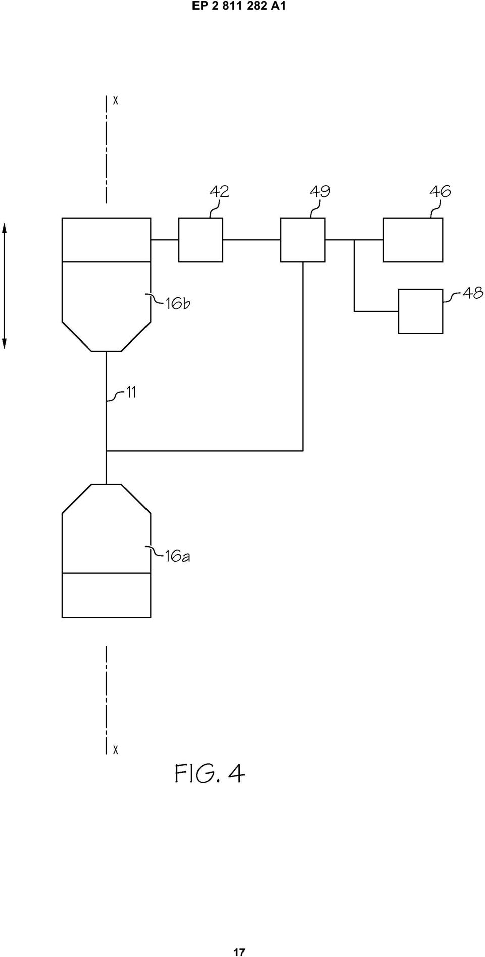
19 EP A1 19
20 EP A1

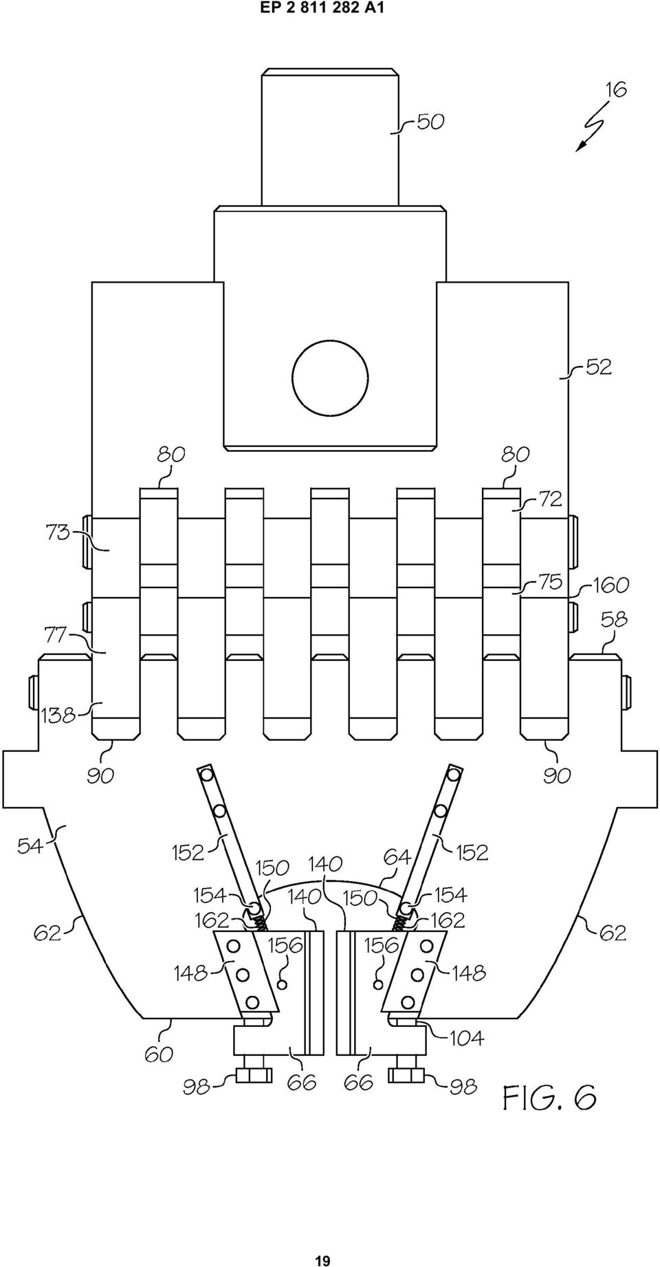
*EP001520563A1* EP 1 520 563 A1 (19) (11) EP 1 520 563 A1 (12) EUROPEAN PATENT APPLICATION. (43) Date of publication: 06.04.2005 Bulletin 2005/14
 (11) EP 1 520 563 A1 (12) EUROPEAN PATENT APPLICATION. (43) Date of publication: 06.04.2005 Bulletin 2005/14") (19) Europäisches Patentamt European Patent Office Office européen des brevets *EP001520563A1* (11) EP 1 520 563 A1 (12) EUROPEAN PATENT APPLICATION (43) Date of publication: 06.04.2005 Bulletin 2005/14
(19) Europäisches Patentamt European Patent Office Office européen des brevets *EP001520563A1* (11) EP 1 520 563 A1 (12) EUROPEAN PATENT APPLICATION (43) Date of publication: 06.04.2005 Bulletin 2005/14
TEPZZ 9 _88_A_T EP 2 921 881 A1 (19) (11) EP 2 921 881 A1 (12) EUROPEAN PATENT APPLICATION
 (11) EP 2 921 881 A1 (12) EUROPEAN PATENT APPLICATION") (19) TEPZZ 9 _88_A_T (11) EP 2 921 881 A1 (12) EUROPEAN PATENT APPLICATION (43) Date of publication: 23.09.1 Bulletin 1/39 (21) Application number: 1416041.2 (1) Int Cl.: G01T 1/ (06.01) G03B 42/02 (06.01)
(19) TEPZZ 9 _88_A_T (11) EP 2 921 881 A1 (12) EUROPEAN PATENT APPLICATION (43) Date of publication: 23.09.1 Bulletin 1/39 (21) Application number: 1416041.2 (1) Int Cl.: G01T 1/ (06.01) G03B 42/02 (06.01)
TEPZZ 87_546A T EP 2 871 546 A2 (19) (11) EP 2 871 546 A2 (12) EUROPEAN PATENT APPLICATION. (51) Int Cl.: G05B 19/05 (2006.01)
 (11) EP 2 871 546 A2 (12) EUROPEAN PATENT APPLICATION. (51) Int Cl.: G05B 19/05 (2006.01)") (19) TEPZZ 87_46A T (11) EP 2 871 46 A2 (12) EUROPEAN PATENT APPLICATION (43) Date of publication: 13.0.1 Bulletin 1/ (1) Int Cl.: G0B 19/0 (06.01) (21) Application number: 14188238.1 (22) Date of filing:
(19) TEPZZ 87_46A T (11) EP 2 871 46 A2 (12) EUROPEAN PATENT APPLICATION (43) Date of publication: 13.0.1 Bulletin 1/ (1) Int Cl.: G0B 19/0 (06.01) (21) Application number: 14188238.1 (22) Date of filing:
EP 2 455 926 A1 (19) (11) EP 2 455 926 A1 (12) EUROPEAN PATENT APPLICATION. (43) Date of publication: 23.05.2012 Bulletin 2012/21
 (11) EP 2 455 926 A1 (12) EUROPEAN PATENT APPLICATION. (43) Date of publication: 23.05.2012 Bulletin 2012/21") (19) (12) EUROPEAN PATENT APPLICATION (11) EP 2 4 926 A1 (43) Date of publication: 23.0.2012 Bulletin 2012/21 (21) Application number: 11190024.7 (1) Int Cl.: G08B 2/14 (2006.01) G08B 2/00 (2006.01) G0B
(19) (12) EUROPEAN PATENT APPLICATION (11) EP 2 4 926 A1 (43) Date of publication: 23.0.2012 Bulletin 2012/21 (21) Application number: 11190024.7 (1) Int Cl.: G08B 2/14 (2006.01) G08B 2/00 (2006.01) G0B
TEPZZ 9 Z5A_T EP 2 922 305 A1 (19) (11) EP 2 922 305 A1. (12) EUROPEAN PATENT APPLICATION published in accordance with Art.
 (11) EP 2 922 305 A1. (12) EUROPEAN PATENT APPLICATION published in accordance with Art.") (19) TEPZZ 9 ZA_T (11) EP 2 922 A1 (12) EUROPEAN PATENT APPLICATION published in accordance with Art. 13(4) EPC (43) Date of publication: 23.09.1 Bulletin 1/39 (21) Application number: 1386446.2 (22) Date
(19) TEPZZ 9 ZA_T (11) EP 2 922 A1 (12) EUROPEAN PATENT APPLICATION published in accordance with Art. 13(4) EPC (43) Date of publication: 23.09.1 Bulletin 1/39 (21) Application number: 1386446.2 (22) Date
TEPZZ 6_Z76 A_T EP 2 610 763 A1 (19) (11) EP 2 610 763 A1 (12) EUROPEAN PATENT APPLICATION. (51) Int Cl.:
 (11) EP 2 610 763 A1 (12) EUROPEAN PATENT APPLICATION. (51) Int Cl.:") (19) TEPZZ 6_Z76 A_T (11) EP 2 6 763 A1 (12) EUROPEAN PATENT APPLICATION (43) Date of publication: 03.07.2013 Bulletin 2013/27 (51) Int Cl.: G06F 17/30 (2006.01) (21) Application number: 12192220.7 (22)
(19) TEPZZ 6_Z76 A_T (11) EP 2 6 763 A1 (12) EUROPEAN PATENT APPLICATION (43) Date of publication: 03.07.2013 Bulletin 2013/27 (51) Int Cl.: G06F 17/30 (2006.01) (21) Application number: 12192220.7 (22)
TEPZZ 69 _ZA T EP 2 692 310 A2 (19) (11) EP 2 692 310 A2. (12) EUROPEAN PATENT APPLICATION published in accordance with Art.
 (11) EP 2 692 310 A2. (12) EUROPEAN PATENT APPLICATION published in accordance with Art.") (19) TEPZZ 69 _ZA T (11) EP 2 692 3 A2 (12) EUROPEAN PATENT APPLICATION published in accordance with Art. 13(4) EPC (43) Date of publication: 0.02.14 Bulletin 14/06 (21) Application number: 1276632.0 (22)
(19) TEPZZ 69 _ZA T (11) EP 2 692 3 A2 (12) EUROPEAN PATENT APPLICATION published in accordance with Art. 13(4) EPC (43) Date of publication: 0.02.14 Bulletin 14/06 (21) Application number: 1276632.0 (22)
TEPZZ 87657ZA_T EP 2 876 570 A1 (19) (11) EP 2 876 570 A1 (12) EUROPEAN PATENT APPLICATION
 (11) EP 2 876 570 A1 (12) EUROPEAN PATENT APPLICATION") (19) TEPZZ 8767ZA_T (11) EP 2 876 70 A1 (12) EUROPEAN PATENT APPLICATION (43) Date of publication: 27.0.201 Bulletin 201/22 (21) Application number: 14189809.8 (1) Int Cl.: G06F 21/34 (2013.01) G08B 13/196
(19) TEPZZ 8767ZA_T (11) EP 2 876 70 A1 (12) EUROPEAN PATENT APPLICATION (43) Date of publication: 27.0.201 Bulletin 201/22 (21) Application number: 14189809.8 (1) Int Cl.: G06F 21/34 (2013.01) G08B 13/196
EP 2 354 708 A2 (19) (11) EP 2 354 708 A2 (12) EUROPEAN PATENT APPLICATION. (43) Date of publication: 10.08.2011 Bulletin 2011/32
 (11) EP 2 354 708 A2 (12) EUROPEAN PATENT APPLICATION. (43) Date of publication: 10.08.2011 Bulletin 2011/32") (19) (12) EUROPEAN PATENT APPLICATION (11) EP 2 354 708 A2 (43) Date of publication:.08.2011 Bulletin 2011/32 (51) Int Cl.: F24H 3/08 (2006.01) F24H 8/00 (2006.01) (21) Application number: 111536.8 (22)
(19) (12) EUROPEAN PATENT APPLICATION (11) EP 2 354 708 A2 (43) Date of publication:.08.2011 Bulletin 2011/32 (51) Int Cl.: F24H 3/08 (2006.01) F24H 8/00 (2006.01) (21) Application number: 111536.8 (22)
Common Mechanical Engineering Terms
 Common Mechanical Engineering Terms Ball and Detent (n) A simple mechanical arrangement used to hold a moving part in a temporarily fixed position relative to another part. The ball slides within a bored
TEPZZ 69 49A_T EP 2 693 349 A1 (19) (11) EP 2 693 349 A1 (12) EUROPEAN PATENT APPLICATION. (51) Int Cl.: G06F 17/30 (2006.01)
 (11) EP 2 693 349 A1 (12) EUROPEAN PATENT APPLICATION. (51) Int Cl.: G06F 17/30 (2006.01)") (19) TEPZZ 69 49A_T (11) EP 2 693 349 A1 (12) EUROPEAN PATENT APPLICATION (43) Date of publication: 0.02.2014 Bulletin 2014/06 (1) Int Cl.: G06F 17/30 (2006.01) (21) Application number: 13160696.4 (22)
(19) TEPZZ 69 49A_T (11) EP 2 693 349 A1 (12) EUROPEAN PATENT APPLICATION (43) Date of publication: 0.02.2014 Bulletin 2014/06 (1) Int Cl.: G06F 17/30 (2006.01) (21) Application number: 13160696.4 (22)
TEPZZ 68575_A_T EP 2 685 751 A1 (19) (11) EP 2 685 751 A1. (12) EUROPEAN PATENT APPLICATION published in accordance with Art.
 (11) EP 2 685 751 A1. (12) EUROPEAN PATENT APPLICATION published in accordance with Art.") (19) TEPZZ 687_A_T (11) EP 2 68 71 A1 (12) EUROPEAN PATENT APPLICATION published in accordance with Art. 3(4) EPC (43) Date of publication:.01.14 Bulletin 14/03 (21) Application number: 1278849.6 (22)
(19) TEPZZ 687_A_T (11) EP 2 68 71 A1 (12) EUROPEAN PATENT APPLICATION published in accordance with Art. 3(4) EPC (43) Date of publication:.01.14 Bulletin 14/03 (21) Application number: 1278849.6 (22)
TEPZZ 84 587A_T EP 2 843 587 A1 (19) (11) EP 2 843 587 A1 (12) EUROPEAN PATENT APPLICATION. (51) Int Cl.: G06F 21/64 (2013.01)
 (11) EP 2 843 587 A1 (12) EUROPEAN PATENT APPLICATION. (51) Int Cl.: G06F 21/64 (2013.01)") (19) TEPZZ 84 87A_T (11) EP 2 843 87 A1 (12) EUROPEAN PATENT APPLICATION (43) Date of publication: 04.03.201 Bulletin 201/ (1) Int Cl.: G06F 21/64 (2013.01) (21) Application number: 13181902.1 (22) Date
(19) TEPZZ 84 87A_T (11) EP 2 843 87 A1 (12) EUROPEAN PATENT APPLICATION (43) Date of publication: 04.03.201 Bulletin 201/ (1) Int Cl.: G06F 21/64 (2013.01) (21) Application number: 13181902.1 (22) Date
EP 2 366 418 A2 (19) (11) EP 2 366 418 A2 (12) EUROPEAN PATENT APPLICATION. (43) Date of publication: 21.09.2011 Bulletin 2011/38
 (11) EP 2 366 418 A2 (12) EUROPEAN PATENT APPLICATION. (43) Date of publication: 21.09.2011 Bulletin 2011/38") (19) (12) EUROPEAN PATENT APPLICATION (11) EP 2 366 418 A2 (43) Date of publication: 21.09.2011 Bulletin 2011/38 (21) Application number: 11158108.8 (51) Int Cl.: A61M 5/36 (2006.01) A61M 5/315 (2006.01)
(19) (12) EUROPEAN PATENT APPLICATION (11) EP 2 366 418 A2 (43) Date of publication: 21.09.2011 Bulletin 2011/38 (21) Application number: 11158108.8 (51) Int Cl.: A61M 5/36 (2006.01) A61M 5/315 (2006.01)
EUROPEAN PATENT APPLICATION. Hudson, NC 28638 (US) Chancery Lane London WC2A 1QU (GB)
 Chancery Lane London WC2A 1QU (GB)") (19) (12) Europaisches Patentamt European Patent Office Office europeen een des brevets EUROPEAN PATENT APPLICATION EP 0 889 344 A1 (43) Date of publication: (51) nt CI.6: G 02 B 6/44 07.01.1999 Bulletin
(19) (12) Europaisches Patentamt European Patent Office Office europeen een des brevets EUROPEAN PATENT APPLICATION EP 0 889 344 A1 (43) Date of publication: (51) nt CI.6: G 02 B 6/44 07.01.1999 Bulletin
TEPZZ 65Z79 A_T EP 2 650 793 A1 (19) (11) EP 2 650 793 A1. (12) EUROPEAN PATENT APPLICATION published in accordance with Art.
 (11) EP 2 650 793 A1. (12) EUROPEAN PATENT APPLICATION published in accordance with Art.") (19) TEPZZ 65Z79 A_T (11) EP 2 650 793 A1 (12) EUROPEAN PATENT APPLICATION published in accordance with Art. 153(4) EPC (43) Date of publication: 16.10.2013 Bulletin 2013/42 (21) Application number: 12818771.3
(19) TEPZZ 65Z79 A_T (11) EP 2 650 793 A1 (12) EUROPEAN PATENT APPLICATION published in accordance with Art. 153(4) EPC (43) Date of publication: 16.10.2013 Bulletin 2013/42 (21) Application number: 12818771.3
UNIT II Robots Drive Systems and End Effectors Part-A Questions
 UNIT II Robots Drive Systems and End Effectors Part-A Questions 1. Define End effector. End effector is a device that is attached to the end of the wrist arm to perform specific task. 2. Give some examples
SECTION G2: CABLE PROCESSOR MODULE MAINTENANCE
 SECTION G2: CABLE PROCESSOR MODULE MAINTENANCE Cable Processor Module overview WARNING! When tipping the Cable Processor Module back, (after removing the toggle arm pin), use extreme caution not to drop
EP 2 365 669 A1 (19) (11) EP 2 365 669 A1 (12) EUROPEAN PATENT APPLICATION. (43) Date of publication: 14.09.2011 Bulletin 2011/37
 (11) EP 2 365 669 A1 (12) EUROPEAN PATENT APPLICATION. (43) Date of publication: 14.09.2011 Bulletin 2011/37") (19) (12) EUROPEAN PATENT APPLICATION (11) EP 2 36 669 A1 (43) Date of publication: 14.09.11 Bulletin 11/37 (1) Int Cl.: H04L 12/8 (06.01) (21) Application number: 00243.6 (22) Date of filing:.03. (84)
(19) (12) EUROPEAN PATENT APPLICATION (11) EP 2 36 669 A1 (43) Date of publication: 14.09.11 Bulletin 11/37 (1) Int Cl.: H04L 12/8 (06.01) (21) Application number: 00243.6 (22) Date of filing:.03. (84)
TEPZZ 94Z968A_T EP 2 940 968 A1 (19) (11) EP 2 940 968 A1 (12) EUROPEAN PATENT APPLICATION. (51) Int Cl.: H04L 29/08 (2006.01)
 (11) EP 2 940 968 A1 (12) EUROPEAN PATENT APPLICATION. (51) Int Cl.: H04L 29/08 (2006.01)") (19) TEPZZ 94Z968A_T (11) EP 2 940 968 A1 (12) EUROPEAN PATENT APPLICATION (43) Date of publication: 04.11.20 Bulletin 20/4 (1) Int Cl.: H04L 29/08 (2006.01) (21) Application number: 1430649.7 (22) Date
(19) TEPZZ 94Z968A_T (11) EP 2 940 968 A1 (12) EUROPEAN PATENT APPLICATION (43) Date of publication: 04.11.20 Bulletin 20/4 (1) Int Cl.: H04L 29/08 (2006.01) (21) Application number: 1430649.7 (22) Date
EP 1 675 420 A1 (19) (11) EP 1 675 420 A1 (12) EUROPEAN PATENT APPLICATION. (43) Date of publication: 28.06.2006 Bulletin 2006/26
 (11) EP 1 675 420 A1 (12) EUROPEAN PATENT APPLICATION. (43) Date of publication: 28.06.2006 Bulletin 2006/26") (19) Europäisches Patentamt European Patent Office Office européen des brevets (12) EUROPEAN PATENT APPLICATION (11) EP 1 67 4 A1 (43) Date of publication: 28.06.06 Bulletin 06/26 (1) Int Cl.: H04Q 7/34
(19) Europäisches Patentamt European Patent Office Office européen des brevets (12) EUROPEAN PATENT APPLICATION (11) EP 1 67 4 A1 (43) Date of publication: 28.06.06 Bulletin 06/26 (1) Int Cl.: H04Q 7/34
BUILD A TABLETOP LOOM
 BUILD A TABLETOP LOOM From 1" x 2" stock (actual 3/4" x 1"1/2) cut: 4 pieces 15" long 4 pieces 5"1/2 long Use the above to make 2 frames for the front and back of the loom. From 1" x 4" stock (actual 3/4"
Module 5 Couplings. Version 2 ME, IIT Kharagpur
 Module 5 Couplings Lesson 1 Introduction, types and uses Instructional Objectives At the end of this lesson, the students should have the knowledge of The function of couplings in machinery. Different
Umted States Patent [19] [11] Patent Number: 4,854,653 Lakso [45] Date of Patent: Aug. 8, 1989
![Umted States Patent [19] [11] Patent Number: 4,854,653 Lakso [45] Date of Patent: Aug. 8, 1989](/thumbs/27/10122812.jpg "Umted States Patent [19] [11] Patent Number: 4,854,653 Lakso [45] Date of Patent: Aug. 8, 1989") . Umted States Patent [19] [11] Patent Number: 4,854,653 Lakso [45] Date of Patent: Aug. 8, 1989 * [54] MULTIPLE INTERLOCKING SYSTEM FOR [56] References Cited FILE CABINETS, E.G. U.S. PATENT DOCUMENTS
. Umted States Patent [19] [11] Patent Number: 4,854,653 Lakso [45] Date of Patent: Aug. 8, 1989 * [54] MULTIPLE INTERLOCKING SYSTEM FOR [56] References Cited FILE CABINETS, E.G. U.S. PATENT DOCUMENTS
C O N V E Y O R C O M P O N E N T S C H A I N S B E L T S B E A R I N G S
 C O N V E Y O R C O M P O N E N T S C H A I N S B E L T S B E A R I N G S January 2009 Issue 6 Valu Guide Brackets The Ultimate in Adjustability and Cost Savings Valu Guide brackets are part of a family
POWERS Controls No. 4 Pneumatic Damper Actuator
 POWERS Controls No. 4 Pneumatic Damper Actuator Technical Instructions Document No. 155-032P25 AP 331-2 Actuator Assembly 331-2929 Typical Actuator Assembly 331-2904 Typical Actuator Assembly 331-3000
Our patent and trade mark attorneys are here to help you protect and profit from your ideas, making sure they re working every bit as hard as you do.
 Our patent and trade mark attorneys are here to help you protect and profit from your ideas, making sure they re working every bit as hard as you do. Our people work with everyone from multi-nationals
SAMPLE TEST PAPER - I
 SCHEME E SAMPLE TEST PAPER - I Course Name : Mechanical Engineering Group Course Code : AE/PG/PT/ME/MH/FE Semester : Third Subject : Mechanical Engineering Drawing 12042 Time : 90 Minutes Marks: 25 Instruction:
Lathe Milling Attachment
 Lathe Milling Attachment By L C. MASON BY CLEVERLY stacking cold-rolled flat stock together, T-slots and slide for this lathe milling attachment are made without costly machinery. In fact, only two tools,
Linear modules Lifting units Rotary modules Grip modules Inductive proximity switches Plug connectors
 20000 Linear modules Lifting units Rotary modules Grip modules Inductive proximity switches Plug connectors 23000 22000 21000 20000 09000 08000 07000 06000 05000 04000 03000 02000 01000 823 Notes 824 Technical
TEPZZ 8898 7A_T EP 2 889 827 A1 (19) (11) EP 2 889 827 A1 (12) EUROPEAN PATENT APPLICATION. (51) Int Cl.: G06Q 40/04 (2012.01)
 (11) EP 2 889 827 A1 (12) EUROPEAN PATENT APPLICATION. (51) Int Cl.: G06Q 40/04 (2012.01)") (19) TEPZZ 8898 7A_T (11) EP 2 889 827 A1 (12) EUROPEAN PATENT APPLICATION (43) Date of publication: 01.07.201 Bulletin 201/27 (1) Int Cl.: G06Q 40/04 (2012.01) (21) Application number: 14199864.1 (22)
(19) TEPZZ 8898 7A_T (11) EP 2 889 827 A1 (12) EUROPEAN PATENT APPLICATION (43) Date of publication: 01.07.201 Bulletin 201/27 (1) Int Cl.: G06Q 40/04 (2012.01) (21) Application number: 14199864.1 (22)
EP 2 492 881 A2 (19) (11) EP 2 492 881 A2 (12) EUROPEAN PATENT APPLICATION. (43) Date of publication: 29.08.2012 Bulletin 2012/35
 (11) EP 2 492 881 A2 (12) EUROPEAN PATENT APPLICATION. (43) Date of publication: 29.08.2012 Bulletin 2012/35") (19) (12) EUROPEAN PATENT APPLICATION (11) EP 2 492 881 A2 (43) Date of publication: 29.08.2012 Bulletin 2012/35 (51) Int Cl.: G08B 13/16 (2006.01) G08B 25/08 (2006.01) (21) Application number: 12386006.6
(19) (12) EUROPEAN PATENT APPLICATION (11) EP 2 492 881 A2 (43) Date of publication: 29.08.2012 Bulletin 2012/35 (51) Int Cl.: G08B 13/16 (2006.01) G08B 25/08 (2006.01) (21) Application number: 12386006.6
MONDOATHENS BASKETBALL SET (Reference PK110)
") MONDOATHENS BASKETBALL SET (Reference PK110) DESCRIPTION The MONDOATHENS backstop unit is mainly designed for multi-sports pavilions and installations where the highest-level basketball competitions are
MONDOATHENS BASKETBALL SET (Reference PK110) DESCRIPTION The MONDOATHENS backstop unit is mainly designed for multi-sports pavilions and installations where the highest-level basketball competitions are
Section 5: Machine Overview
 Section 5: Machine Overview Machine Floor Plan Machine Specifications Sequence of Operation Theory of Operation Sensor Location Floor Plan 2007 Douglas Machine Inc. 5.1 Machine Floor Plan Figure 5.1: Machine
LEGACY REPORT ER-5110. www.icc-es.org. ICC Evaluation Service, Inc. Reissued November 1, 2003. Legacy report on the 1997 Uniform Building Code
 LEGACY REPORT Reissued November 1, 2003 ICC Evaluation Service, Inc. www.icc-es.org Business/Regional Office # 5360 Workman Mill Road, Whittier, California 90601 # (562) 699-0543 Regional Office # 900
Title (fr) SOURCE IONIQUE INTERNE DOUBLE POUR PRODUCTION DE FAISCEAU DE PARTICULES AVEC UN CYCLOTRON
 SOURCE IONIQUE INTERNE DOUBLE POUR PRODUCTION DE FAISCEAU DE PARTICULES AVEC UN CYCLOTRON") Title (en) A TWIN INTERNAL ION SOURCE FOR PARTICLE BEAM PRODUCTION WITH A CYCLOTRON Title (de) DOPPELTE INTERNE IONENQUELLE FÜR PARTIKELSTRAHLHERSTELLUNG MIT EINEM ZYKLOTRON Title (fr) SOURCE IONIQUE INTERNE
Title (en) A TWIN INTERNAL ION SOURCE FOR PARTICLE BEAM PRODUCTION WITH A CYCLOTRON Title (de) DOPPELTE INTERNE IONENQUELLE FÜR PARTIKELSTRAHLHERSTELLUNG MIT EINEM ZYKLOTRON Title (fr) SOURCE IONIQUE INTERNE
FTC 2015-2016 DIY Mountain Build Guide
 FTC 2015-2016 DIY Mountain Build Guide Assembly Instructions Check out the DIY2015-2016 Prints and BoM for individual part details. Release 1.0 9/10/15 Page 1 This guide and Bill of Materials are for constructing
MACHINE DRAWING QUESTION BANK. 2. What are the parts not usually sectioned? (Nov 04)
") MACHINE DRAWING QUESTION BANK UNIT-I 1. Answer the following: Sketch a i. Hexagonal nut convention, ii. Convention of a stud bolt. (Nov 04) 2. What are the parts not usually sectioned? (Nov 04) 3 Answer
MACHINE DRAWING QUESTION BANK UNIT-I 1. Answer the following: Sketch a i. Hexagonal nut convention, ii. Convention of a stud bolt. (Nov 04) 2. What are the parts not usually sectioned? (Nov 04) 3 Answer
RL HW / RL HW+ / RL HGW / RL HV / RL HVPW/RL HVPW-G
 Auto-Levelling Rotary Laser Level RL HW / RL HW+ / RL HGW / RL HV / RL HVPW/RL HVPW-G 77-496 / 77-429 / 77-439 / 77-497 / 77-427/ 77-441 Please read these instructions before operating the product Auto-Levelling
int. CI e: E05B 65/00, E05B 15/00
 J Europaisches Patentamt European Patent Office Office europeen des brevets Publication number: 0 672 808 A1 EUROPEAN PATENT APPLICATION Application number: 95200564.3 int. CI e: E05B 65/00, E05B 15/00
Ulllted States Patent [19] [11] Patent Number: 6,009,588. Rutkowski [45] Date of Patent: Jan. 4, 2000
![Ulllted States Patent [19] [11] Patent Number: 6,009,588. Rutkowski [45] Date of Patent: Jan. 4, 2000](/thumbs/30/13940583.jpg "Ulllted States Patent [19] [11] Patent Number: 6,009,588. Rutkowski [45] Date of Patent: Jan. 4, 2000") US006009588A Ulllted States Patent [19] [11] Patent Number: 6,009,588 Rutkowski [45] Date of Patent: Jan. 4, 2000 [54] DRAIN CLEANING APPARATUS 4,686,732 8/1987 Irwin..... 15/104.33 4,914,775 4/1990 Kirk..
US006009588A Ulllted States Patent [19] [11] Patent Number: 6,009,588 Rutkowski [45] Date of Patent: Jan. 4, 2000 [54] DRAIN CLEANING APPARATUS 4,686,732 8/1987 Irwin..... 15/104.33 4,914,775 4/1990 Kirk..
Design of a Universal Robot End-effector for Straight-line Pick-up Motion
 Session Design of a Universal Robot End-effector for Straight-line Pick-up Motion Gene Y. Liao Gregory J. Koshurba Wayne State University Abstract This paper describes a capstone design project in developing
TEPZZ 79ZZ8_A_T EP 2 790 081 A1 (19) (11) EP 2 790 081 A1 (12) EUROPEAN PATENT APPLICATION. (43) Date of publication: 15.10.2014 Bulletin 2014/42
 (11) EP 2 790 081 A1 (12) EUROPEAN PATENT APPLICATION. (43) Date of publication: 15.10.2014 Bulletin 2014/42") (19) TEPZZ 79ZZ8_A_T (11) EP 2 790 081 A1 (12) EUROPEAN PATENT APPLICATION (43) Date of publication: 1..14 Bulletin 14/42 (1) Int Cl.: G0D 23/19 (06.01) (21) Application number: 1414221.7 (22) Date of
(19) TEPZZ 79ZZ8_A_T (11) EP 2 790 081 A1 (12) EUROPEAN PATENT APPLICATION (43) Date of publication: 1..14 Bulletin 14/42 (1) Int Cl.: G0D 23/19 (06.01) (21) Application number: 1414221.7 (22) Date of
TEPZZ 799965A_T EP 2 799 965 A1 (19) (11) EP 2 799 965 A1. (12) EUROPEAN PATENT APPLICATION published in accordance with Art.
 (11) EP 2 799 965 A1. (12) EUROPEAN PATENT APPLICATION published in accordance with Art.") (19) TEPZZ 79996A_T (11) EP 2 799 96 A1 (12) EUROPEAN PATENT APPLICATION published in accordance with Art. 13(4) EPC (43) Date of publication: 0.11.14 Bulletin 14/4 (21) Application number: 14727698.4
(19) TEPZZ 79996A_T (11) EP 2 799 96 A1 (12) EUROPEAN PATENT APPLICATION published in accordance with Art. 13(4) EPC (43) Date of publication: 0.11.14 Bulletin 14/4 (21) Application number: 14727698.4
ANSWER KEY. Work and Machines
 Chapter Project Worksheet 1 1. inclined plane, wedge, screw, lever, wheel and axle, pulley 2. pulley 3. lever 4. inclined plane 5. Answers will vary: top, side, or bottom 6. Answers will vary; only one
MODEL 565E - 22 TON AIR/HYDRAULIC AXLE JACK
 1 565AKHU HYDRAULIC 1.22 O-RING - 2 REQUIRED UNIT 1.23 O-RING COMPLETE 1.24 TEFLON O-RING 2 REQUIRED 1.3 EXTENSION SCREW 1.3A SPRING PIN 1.4 SPRING SUPPORT 1.5 SCREW BUSHING 1.6 Y SHAPE SEAL RING 1.7 HEAD
ENGLISH FORK GUIDE 2013
 FORK GUIDE 2013 ENGLISH 1 With a brand which is synonymous with specialists in forest products handling attachments, BOLZONI AURAMO offers its expertise and market leading attachments for all requirements,
Technical Information
 Technical Information This section of the catalogue provides technical information that will help specify, install and maintain Surelock McGill devices and components. The topics are listed below: Blast
Section. Tolerances. Aluminum Extrusion Manual. 4th Edition
 Section 8 Tolerances Aluminum Extrusion Manual 4th Edition Section 8 How straight is straight enough? How flat is flat enough? How uniform must a wall thickness be in order to be acceptable? These are
Suspension and Steering Systems Operation. The Steering/Suspension System (Overview)
") Suspension and Steering Systems Operation Below is an overview of the suspension and steering systems The Steering/Suspension System (Overview) "Suspension," when discussing cars, refers to the use of
Suspension and Steering Systems Operation Below is an overview of the suspension and steering systems The Steering/Suspension System (Overview) "Suspension," when discussing cars, refers to the use of
Manual piston sampler...m 11
 SAMPLING Manual piston sampler...m 11 Screw sampler...prec 22...PREC 100 Slide sampler...pr 55 Rotative screw sampler...prv Piston sampler...p 11 Sampler on belt conveyor...pba Rotating cup sampler...pgr
Use of Strain Gauge Rosette to Investigate Stress concentration in Isotropic and Orthotropic Plate with Circular Hole
 Use of Strain Gauge Rosette to Investigate Stress concentration in Isotropic and Orthotropic Plate with Circular Hole Mr.V.G.Aradhye 1, Prof.S.S.Kulkarni 2 1 PG Scholar, Mechanical department, SKN Sinhgad
Mechanical Reasoning Review
 Mechanical Reasoning Review Work can be made easier or faster through practical applications of simple and/or compound machines. This is called mechanical advantage - in other words, using the principal
INSTALLATION AND OPERATING INSTRUCTIONS For Model GL1 Gate Locks
 Securitron Magnalock Corp. www.securitron.com ASSA ABLOY, the global leader Tel 800.624.5625 techsupport@securitron.com in door opening solutions INSTALLATION AND OPERATING INSTRUCTIONS For Model GL1 Gate
Step 11 Static Load Testing
 Step 11 Static Load Testing Test loading is the most definitive method of determining load capacity of a pile. Testing a pile to failure provides valuable information to the design engineer and is recommended
Lecture slides on rolling By: Dr H N Dhakal Lecturer in Mechanical and Marine Engineering, School of Engineering, University of Plymouth
 Lecture slides on rolling By: Dr H N Dhakal Lecturer in Mechanical and Marine Engineering, School of Engineering, University of Plymouth Bulk deformation forming (rolling) Rolling is the process of reducing
CHAPTER 65 TAIL ROTOR DRIVE SYSTEM. Section Title Page
 CHAPTER 65 TAIL ROTOR DRIVE SYSTEM Section Title Page 65-00 Description........................................ 65.1 65-10 Tail Rotor Drive Fan Shaft.............................. 65.1 65-20 Tail Rotor
Maxi-Stamper. 200 to 1,000 Tons STAMPING OUT DOWNTIME
 TM Maxi-Stamper 200 to 1,000 Tons STAMPING OUT DOWNTIME Standard Features Steel Fabricated Construction Drive Capacity Rated 1/2 Above Bottom of Stroke Self-Diagnostic Solid State Controller Moveable Operator
TopSky DLG Installation Manual
 TopSky DLG Installation Manual Attention: Because after the compound materials solidify, there will be ammonia iris on the surface, which affect the bonding strength afterwards. Please polish with sandpaper
Autodesk Fusion 360: Assemblies. Overview
 Overview In this module you will learn how different components can be put together to create an assembly. We will use several tools in Fusion 360 to make sure that these assemblies are constrained appropriately
SUPPLEMENTAL TECHNICAL SPECIFICATIONS BI-DIRECTIONAL STATIC LOAD TESTING OF DRILLED SHAFTS
 July 14, 2015 1.0 GENERAL BI-DIRECTIONAL STATIC LOAD TESTING OF DRILLED SHAFTS This work shall consist of furnishing all materials, equipment, labor, and incidentals necessary for conducting bi-directional
System. Stability. Security. Integrity. 150 Helical Anchor
 Model 150 HELICAL ANCHOR System PN #MBHAT Stability. Security. Integrity. 150 Helical Anchor System About Foundation Supportworks is a network of the most experienced and knowledgeable foundation repair
2010 APPLICATION REFERENCE GUIDE
 2010 APPLICATION REFERENCE GUIDE INDEX QUALITY POLICY 2 ERGO ASSIST STANDARD 4-13 CUSTOM 14-18 END EFFECTORS 19-24 LIFT ASSIST 25-41 FIXTURED TOOLS 42-53 FIXTURES 54-63 ASSEMBLY TABLES 64-72 CARTS/ DUNNAGE
Rebuild Instructions for 70001 and 70010 Transmission
 Rebuild Instructions for 70001 and 70010 Transmission Brinn, Incorporated 1615 Tech Drive Bay City, MI 48706 Telephone 989.686.8920 Fax 989.686.6520 www.brinninc.com Notice Read all instructions before
Working Drawing and Assemblies. Chapter 10
 Working Drawing and Assemblies Chapter 10 Objectives 1.Define working drawings. 2. Describe how working drawings are used in industry. 3. List the major components of a complete set of working drawings.
(54) (75) (2006.01) (73) (21) (22) (63) Peschel, Schoengeising (DE); (30) Foreign Application Priority Data. Robert Trimpe, Wessling (DE)
 (75) (2006.01) (73) (21) (22) (63) Peschel, Schoengeising (DE); (30) Foreign Application Priority Data. Robert Trimpe, Wessling (DE)") US 20120073912Al (19) United States (12) Patent Application Publication (10) Pub. No.: US 2012/0073912 A1 CAMILO-MARTINEZ et al. (43) Pub. Date: Mar. 29, 2012 (54) (75) (73) (21) (22) (63) PNEUMATICALLY
US 20120073912Al (19) United States (12) Patent Application Publication (10) Pub. No.: US 2012/0073912 A1 CAMILO-MARTINEZ et al. (43) Pub. Date: Mar. 29, 2012 (54) (75) (73) (21) (22) (63) PNEUMATICALLY
Chapter. 4 Mechanism Design and Analysis
 Chapter. 4 Mechanism Design and Analysis 1 All mechanical devices containing moving parts are composed of some type of mechanism. A mechanism is a group of links interacting with each other through joints
ANSI APPROVED 04/11/2014 ANSI APPROVED 08/17/2011. 45 Reaffirmation ANSI APPROVED 02/28/2014. 45 Reaffirmation ANSI APPROVED 05/06/2013
 STANDARDS STATUS REPORT As of November 4, 2015 Note: Dates in RED indicate the last action taken; Highlighted Items Indicate New/Open Items; Grey items have been closed Document TC Status Comments ASME
KIRÁLY TRADING KFT H-1151 Budapest Mogyoród útja 12-14 tel: 061307-3801 Email_pzoli@kiralytrading.hu. Clamps Clamping devices
 04000 Clamps Clamping devices 23000 22000 21000 20000 09000 08000 07000 06000 05000 04000 03000 02000 01000 297 04010 Adjustable straps Tempered steel 1.1191 Black oxide finish nlm 04010-101 Suitable thrust
Pump Skid Fabrication for Magnetic Coupling. Rick Soltis Chief Mechanic City of Bedford
 Pump Skid Fabrication for Magnetic Coupling Rick Soltis Chief Mechanic City of Bedford Contents Magnetic Couplings What They Are, How They Work, Where They re Used Fabrication and Manufacturing of Pump
Two most common lock nut groups: 1-Prevailing Torque Type Lock Nuts:
 Two most common lock nut groups: 1. PREVAILING TORQUE a design feature of the lock nut produces friction between threads of mated components thereby increasing the force needed to tighten as well as loosen
1/29/2008 DR50. Baja Motorsports Inc. P.O. Box 61150 Phoenix, AZ 85082 Toll Free: 888-863-2252 PART NUMBERS PRICES ARE SUBJECT TO CHANGE 1 of 45
 DR50 Toll Free: 888-863-2252 PART NUMBERS PRICES ARE SUBJECT TO CHANGE 1 of 45 CYLINDER & CYLINDER HEAD Part UPC Number Description Baja Description 1 DR50-001 842645074424 CYLINDER 1 1 2 DR50-002 842645074431
1/29/2008 DR70. Baja Motorsports Inc. P.O. Box 61150 Phoenix, AZ 85082 Toll Free: 888-863-2252 PART NUMBERS PRICES ARE SUBJECT TO CHANGE 1 of 43
 DR70 Toll Free: 888-863-2252 PART NUMBERS PRICES ARE SUBJECT TO CHANGE 1 of 43 CYLINDER & CYLINDER HEAD 1 DR70-001 883099044472 CYLINDER 1 1 2 DR70-002 883099044489 GASKET, CYLINDER 1 1 3 DR70-003 883099044496
WHI 90-Minute Rated Veneered Door Frame Installation Instructions
 No. 940-03-10 INSTALLATION INSTRUCTIONS 90 MINUTE RATED VENEERED DOOR FRAME DOOR REQUIREMENTS: Consult the door manufacturer to make sure that the doors are qualified for the hardware to be installed,
PaLLe t trucks Lifting carts t r g in t if L 2435 6815 6836 6856 6842
 l i f t i n g c a r t s Lifting carts The prograe for lifting, transporting and storage From the classical forklift trolley to the machine lifter, from furniture dollies to a chassis with 24 tons load
Precision Miniature Load Cell. Models 8431, 8432 with Overload Protection
 w Technical Product Information Precision Miniature Load Cell with Overload Protection 1. Introduction The load cells in the model 8431 and 8432 series are primarily designed for the measurement of force
I BEAM TRACK INSTALLATION
 PDQ 0/700 FESTOON SYSTEM INSTALLATION AND MAINTENANCE INSTRUCTIONS INTRODUCTION The PDQ Festoon System was designed to run on one of three sizes of I-beams: S x., S8 x 8. and S x.. System trolleys must
TS93 EMR T/PT/TDE. Surface applied door closer
 TS EMR T/PT/TDE Surface applied door closer Installation instructions: Pull side track mount door closer with smoke detector (EMR T) Push side track mount door closer with smoke detector (EMR PT) Double
Pole Lathe and Shave Horse Design
 Pole Lathe and Shave Horse Design These pictures and accompanying words are Copyright Michael Hughes February 2002. They are not to be re-produced, in part or whole, without permission from the author.
How to Build Your Own CornHole Game
 How to Build Your Own CornHole Game DIMENSIONS Here is a diagram with the basic measurements for the Cornhole board game. SUPPLIES 1/2 thick sheet of plywood one 4 x4 or two 2 x4 s 8 long 2 4 s (4) 4 1/2
MEASURING WHEEL ALIGNMENT
 MEASURING WHEEL ALIGNMENT 2003-04 WHEEL ALIGNMENT Specifications & Procedures - Hummer - H2 Steering and vibration complaints are not always the result of improper alignment. One possible cause is wheel
Assembly Instructions for the InteliTrack 3000 Rail Tracking System
 Assembly Instructions for the InteliTrack 3000 Rail Tracking System InteliTrack is a trademark of Sedona Solar Technology. Sedona Solar Technology 16 April 2013 1 1. Before you begin WARNING Safety equipment
DESIGN OF ADAPTIVE MULTI TOOL ARBOR ATTACHMENT
 INTERNATIONAL JOURNAL OF MECHANICAL ENGINEERING AND TECHNOLOGY (IJMET) International Journal of Mechanical Engineering and Technology (IJMET), ISSN 0976 6340(Print), ISSN 0976 6340 (Print) ISSN 0976 6359
Solid shape molding is not desired in injection molding due to following reasons.
 PLASTICS PART DESIGN and MOULDABILITY Injection molding is popular manufacturing method because of its high-speed production capability. Performance of plastics part is limited by its properties which
Stitch Formation in Rotary Hook Sewing Machines ABSTRACT
 Stitch Formation in Rotary Hook Sewing Machines Douglas A. Kerr Issue 3 October 28, 2008 ABSTRACT Most modern general-purpose sewing machines form a lockstitch by way of the rotary hook technique. The
Rules of Actuator and Guide Alignment in Linear Motion Systems
 Rules of Actuator and Guide Alignment in Linear Motion Systems By Gary Rosengren, Director of Engineering Tolomatic, Inc. About the Author Gary Rosengren is Director of Engineering at Tolomatic and has
STEERING HANDLEBAR/FRONT WHEEL/ FRONT SHOCK ABSORBER
 14 14 STEERING HANDLEBAR/FRONT WHEEL/ SCHEMATIC DRAWING ------------------------------------------------- 14-1 SERVICE INFORMATION------------------------------------------------ 14-2 TROUBLESHOOTING-----------------------------------------------------
SAMPLE GUIDE SPECIFICATIONS FOR OSTERBERG CELL LOAD TESTING OF DEEP FOUNDATIONS
 Page 1 of 9 SAMPLE GUIDE SPECIFICATIONS FOR OSTERBERG CELL LOAD TESTING OF DEEP FOUNDATIONS 1. GENERAL REQUIREMENTS 1. Description of Work: This work consists of furnishing all materials, equipment and
Performance Test Method for Intensive Use Chairs FNEW 83-269: A Description of the Test Method with Drawings
 Purdue University Forestry and Natural Resources FNR-179 Furniture Manufacturing Performance Test Method for Intensive Use Chairs FNEW 83-269: A Description of the Test Method with Drawings By Carl A.
(51) Int Cl.: G06F 9/455 (2006.01) G06F 9/50 (2006.01)
 Int Cl.: G06F 9/455 (2006.01) G06F 9/50 (2006.01)") (19) TEPZZ 6987 B_T (11) EP 2 698 711 B1 (12) EUROPEAN PATENT SPECIFICATION (4) Date of publication and mention of the grant of the patent: 0.08.1 Bulletin 1/32 (21) Application number: 118777.8 (22) Date
(19) TEPZZ 6987 B_T (11) EP 2 698 711 B1 (12) EUROPEAN PATENT SPECIFICATION (4) Date of publication and mention of the grant of the patent: 0.08.1 Bulletin 1/32 (21) Application number: 118777.8 (22) Date
AGRICULTURAL COVERING
 1 AGRICULTURAL COVERING Patent number: US2015064415 Date of publication: 2015-03-05 Applicant(s): BEAULIEU TECHNICAL TEXTILES (BE) The present invention is directed to an agricultural covering in form
DUGARD. Machine Tools Since 1939. Dugard 700L Series Heavy Duty CNC Lathes. www.dugard.com
 DUGARD Machine Tools Since 1939 Dugard 700L Series Heavy Duty CNC Lathes www.dugard.com Dugard 700L Heavy Duty CNC Lathe 2000, 3000 or 4000mm bed length Designed for easy and convenient operation The concave
Section A. GENERAL INFORMATION
 Section A. GENERAL INFORMATION I. Description The information and instructions for attaching the sidecar to the right-hand side of the motorcycle are contained in this handbook and must be carefully observed.
Diameter. Swift Lift Round Recess Plug. Note: The diameter of the narrow recess plug is the same as the diameter of the round recess plug.
 P-5 The P-5 is hot forged from carbon steel. The formed head provis spherical seating that the Lifting Eye engages, while a disc-shaped foot is embedd in the concrete. Due to its being a forged part, the
Simple Machines. What are simple machines?
 Definitions to know: Simple Machines Work done when an applied force causes an object to move in the direction of the force Energy ability to cause change; can change the speed, direction, shape, or temperature
Plastic Injection Molding
 Training Objective After watching this video and reviewing the printed material, the student/trainee will understand the principles and physical operations of the plastic injection molding process. An
DR90. Baja Motorsports Inc. P.O. Box 61150 Phoenix, AZ 85082 Toll Free: 888-863-2252 PART NUMBERS AND PRICES ARE SUBJECT TO CHANGE 1 of 51
 DR90 Toll Free: 888-863-2252 PART NUMBERS AND PRICES ARE SUBJECT TO CHANGE 1 of 51 CYLINDER & CYLINDER HEAD 1 DR90-001 842645048166 CYLINDER 1 1 2 DR90-002 842645048173 GASKET, CYLINDER 1 1 3 DR90-003
 HU CZ FI PL SI PT IT ES NO NL FR DK SE IE GB AT DE CH LU 0 10 20 30 40 Foreigners' share Source: Eurostat More trust 3 4 5 6 7 PL HU CZ SI PT GR ES DK FI SE
EP 2 922 249 A1 (19) (11) EP 2 922 249 A1 (12) EUROPEAN PATENT APPLICATION. (43) Date of publication: 23.09.2015 Bulletin 2015/39
 (11) EP 2 922 249 A1 (12) EUROPEAN PATENT APPLICATION. (43) Date of publication: 23.09.2015 Bulletin 2015/39") (19) TEPZZ 9 49A_T (11) EP 2 922 249 A1 (12) EUROPEAN PATENT APPLICATION (43) Date of publication: 23.09. Bulletin /39 (21) Application number: 16003.0 (1) Int Cl.: H04L 12/7 (13.01) H04L 12/717 (13.01)
(19) TEPZZ 9 49A_T (11) EP 2 922 249 A1 (12) EUROPEAN PATENT APPLICATION (43) Date of publication: 23.09. Bulletin /39 (21) Application number: 16003.0 (1) Int Cl.: H04L 12/7 (13.01) H04L 12/717 (13.01)
SERVICE PARTS LIST PAGE 1 OF 6 BASE ASSEMBLY SPECIFY CATALOG NO. AND SERIAL NO. WHEN ORDERING PARTS 12" DUAL BEVEL COMPOUND MITER SAW B27A
 PAGE 1 OF 6 BASE ASSEMBLY 00 0 EXAMPLE: Component Parts (Small #) Are Included When Ordering The Assembly (Large #). SPECIFY CATALOG NO. AND NO. WHEN ORDERING PARTS 1 02-80-0050 Thrust Bearing (1) 2 05-80-0510