(51) Int Cl. 7 : F16L 11/12, F16L 35/00
|
|
|
- Christal Perry
- 8 years ago
- Views:
Transcription
1 (19) Europäisches Patentamt European Patent Office Office européen des brevets *EP B1* (11) EP B1 (12) EUROPEAN PATENT SPECIFICATION (4) Date of publication and mention of the grant of the patent: Bulletin 04/39 (21) Application number: (22) Date of filing: (1) Int Cl. 7 : F16L 11/12, F16L 3/00 (86) International application number: PCT/IB00/ (87) International publication number: WO 00/ ( Gazette 00/1) (4) REINFORCED FLEXIBLE HOSE AND METHOD FOR THE PRODUCTION THEREOF VERSTÄRKTER FLEXIBLER SCHLAUCH UND VERFAHREN ZU SEINER HERSTELLUNG TUYAU SOUPLE RENFORCE ET PROCEDE DE PRODUCTION DE CELUI-CI (84) Designated Contracting States: AT BE CH CY DE DK ES FI FR GB GR IE IT LI LU MC NL PT SE () Priority: IT VI9901 (43) Date of publication of application: Bulletin 02/12 (73) Proprietor: Eurocondotte S.p.A. 360 Vicenza (IT) (72) Inventor: MEZZALIRA, Rinaldo I-3607 Arcugnano (IT) (74) Representative: Vannini, Mario Maroscia & Associati S.r.L., Contra S. Caterina, Vicenza (IT) (6) References cited: EP-A EP-B EP-B WO-A-84/0474 DE-B US-A EP B1 Note: Within nine months from the publication of the mention of the grant of the European patent, any person may give notice to the European Patent Office of opposition to the European patent granted. Notice of opposition shall be filed in a written reasoned statement. It shall not be deemed to have been filed until the opposition fee has been paid. (Art. 99(1) European Patent Convention). Printed by Jouve, 7001 PARIS (FR)
 International application number: PCT/IB00/000778 (87) International publication number: WO 00/077433 (21.12.")
2 1 EP B1 2 Description FIELD OF THE INVENTION [0002] Flexible hoses are known which belong to the cheap category of the market. In order to control production costs, these are produced joining two coaxial tubular layers having reduced thickness, by means of the insertion of a knitted or woven reinforcement therebetween. [0003] The above mentioned types of hoses are usually employed in connection with mounts, joints or irrigation tools having standard size and manufactured on a mass scale. Tubes having a reduced thickness are hard to join to the standard quick-fit joints, therefore a short while after the hose starts being used, water leaks are often found to occur through the joining area. [0004] A further disadvantage of said known hoses is that they are prone to be easily twisted and damaged where they connect with the joint, most often in proximity of the water mains tap. [000] Several attempts to overcome the above shortcomings were made in the past, for instance fixing joints that are pressed and made to be suitable for the hose either at the production stage or resorting to hose joints to be fixed between the hose and the standard joint, said hose joints being made of a similar material to that the tube is made of and further being suitably secured. [0006] Although on the one hand the above solutions lead to a reinforcement of the hose wall, thus making its bending more difficult, on the other hand they bring about an increase in production costs, that makes them not too favourably welcomed by the users of this specific market. [0007] A further disadvantage is that in case the hose breaks and is subject to shortening at its end portions, it turns out to be mandatory to use standard joints that have the known sealing problems deriving from the difficulty there is to find special joints distributed by the normal large-scale retail trade. [0008] In case reinforcements are made by hose joints, it is likewise difficult to find spare hose joints to replace those that cannot be recovered after a damaged hose has been shortened. [0009] EP-A discloses a flexible hose for shower and sanitary fixtures having all the features mentioned in the preamble of the attached claim 1. However, the thickness of one of the inner and outer layers is increased gradually and is not constant along the whole extension of longitudinal end portions. Thus, the end portion with increased thickness must have a relatively long extension in order to provide a sufficient resistance for the joints. SUMMARY OF THE INVENTION [0001] The present invention relates to a reinforced flexible hose, particularly but not exclusively suitable for the field of gardening. BACKGROUND OF THE INVENTION [00] A primary object of the present invention is to provide a new type of hose that is capable of being easily and effectively joined to the standard joints, in so doing maintaining its enhanced sealing properties and avoiding water leaks, while retaining its cost effectiveness at the production stage and remaining comprised in the low-cost category on the market. [0011] A further specific object of the present invention is to design a hose of the type outlined above that features a structure that is capable of minimising the risks of breakage, twisting or detachment at the joining with the tap or with the watering tool. [0012] The above objects are accomplished by providing a reinforced flexible hose that comprises in accordance with the attached claim 1 is characterised in that the increased thickness is substantially constant along the whole extension of the longitudinal portions. [0013] Thanks to said reinforcements, it is thus possible to use joints of the standard type, maintaining a mechanical connection at the reinforced end of the hose, preventing the hose to detach from the joint and reducing the danger of twisting the end portion thereof during handling by the user. [0014] A further object of the present invention is to provide a simple method for the production of a hose according to the present invention, that allows the production of great quantities thereof on a continuous basis at low costs, by using the existing equipment, though suitably modified for that purpose. [001] The above object is accomplished by providing a method for the production of a reinforced flexible hose that in accordance with the attached claim 9 comprises the following steps: a) extruding at least one first inner tubular layer (2) made of plastic material having a substantially constant advancement speed (V); b) weaving a textile fabrics material (4) onto the outer surface of said first layer (3), at the same advancement speed (V); c) extruding at least one second tubular layer (2) made of plastic material at substantially the same advancement speed (V) of said first layer (2) and said tubular reinforcement (4) so as to allow a homogeneous fitting of said layers (2, 3) and form a wall having a predetermined thickness (S); d) providing longitudinal portions (A, B) having an increased thickness (S', S") in said first and/or second tubular layer (2,3) so as to enhance resistance of the hose in order to favour a stable mating to hose end joints or to other irrigation accessories; e) cutting the hose in correspondence of said longitudinal portions (A,B) having increased thickness, 2
![[0003] The above mentioned types of hoses are usually employed in connection with mounts, joints or irrigation tools having standard size and manufactured on a mass scale.](/docs-images/51/13817553/images/page_2.jpg "Tubes having a reduced thickness are hard to join to the standard quick-fit joints, therefore a short while after the hose starts being used, water leaks are often found to occur through the joining")
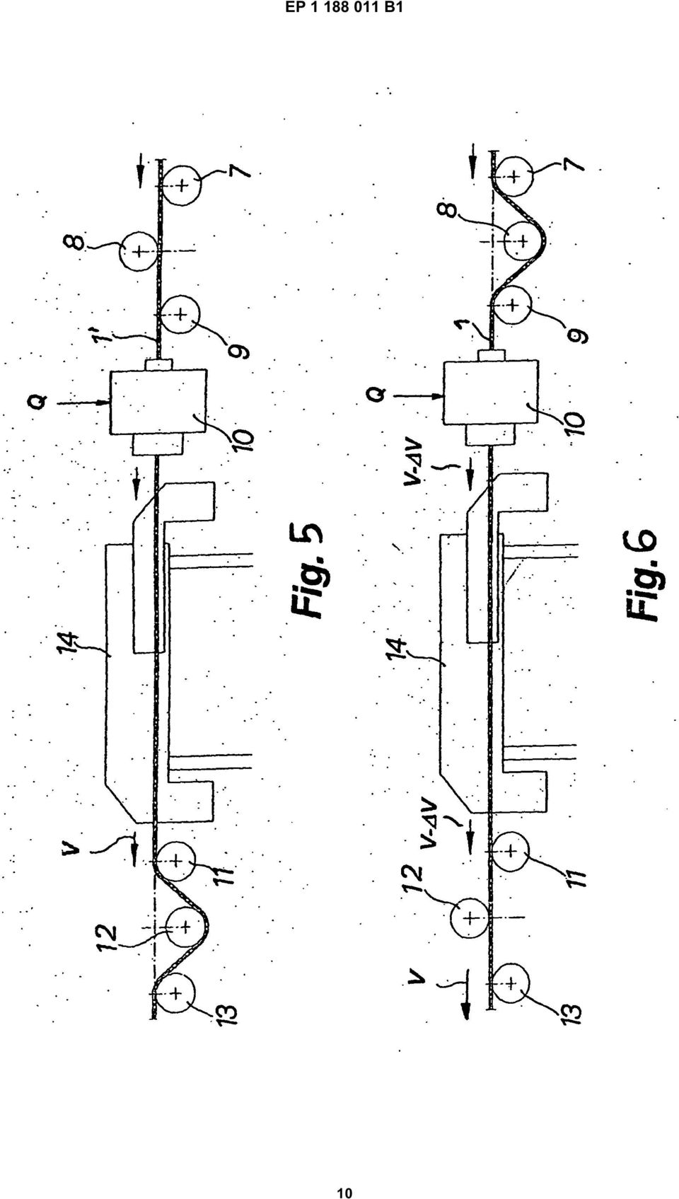
3 3 EP B1 4 characterised in that said increased thickness is made substantially constant along the whole extension (A) of said longitudinal portions. [0016] Step d) can be accomplished by varying the advancement speed of at least one of the said layers in correspondence at said longitudinal portions thereof having greater thickness. The speed change can be accomplished instantaneously, then the speed is kept at a constant value for a portion of its length. [0017] As an alternative, step d) can also be accomplished by varying the flow of the extruded material having increased thickness. [0018] The finished hose alternatively features endlongitudinal portions having increased thickness and being frusto-conically shaped as with their larger side in common, or it may otherwise feature a cylindrically shaped thicker portion. [0019] At the end of the process, the hose is cut in correspondence of the section having maximum diameter or of the middle area of the portion having increased thickness. BRIEF DESCRIPTION OF THE DRAWINGS [00] Further features and advantages of the present invention will be more clearly apparent in the light of the following description of a preferred but not exclusive embodiment, given by way of not limiting example, of a reinforced flexible hose illustrated in the attached drawings, wherein: fig. 1 shows a longitudinal section view of the hose of the prior art, fig. 2 is a cross-sectional view of the hose shown in Fig. 1; fig. 3 is a general perspective view of an embodiment of the reinforced flexible hose according to the present invention; flexible hose according to the present invention; fig. 4 is a longitudinal sectional view of a first embodiment of the present invention; fig. is a schematic side view of a device for the production of a hose according to the present invention, with said device in a first operating position; fig. 6 is a schematic side view of the device shown in Fig. 8, with said device in a second operating phase. DESCRIPTION OF SOME PREFERRED FORMS OF EMBODIMENT [0021] With reference to Figs. 1 and 2 a flexible hose of the prior art is shown, generally indicated with the reference numeral 1, that is essentially formed by two tubular coaxial layers, respectively an inner layer having an inner diameter Di and an outer layer having an outer diameter De, and with a tubular reinforcement or stock 4 made of fibrous material, of the woven or knitted type, that is interposed between the two layers 2, 3 and extends over the entire length thereof. [0022] Layers 2, 3 are made of extruded plastic materials and are mutually joined in correspondence of their mutual contact surface with the interposition of reinforcement 4 so as to form a wall having an overall thickness S that is substantially constant, except the working tolerances connected with the extrusion of layers with the weaving of the reinforcement fabrics 4. [0023] Figs. 3 and 4 show a first embodiment of hose 1 according to the present invention, said hose having a thickness S' along a portion A of its length starting at one end, said thickness being increased with respect to thickness S of the portion of hose 1 that is the furthest from its end. [0024] In this first embodiment, tube wall 1 has either a substantially constant thickness along the whole portion A past circular step 6 or an extremely short conical connecting portion. Thus it will be possible to promote a stable watertight mating with connecting organs or gardening hose joints, thereby avoiding water leakages and any sort of breakages at those hose joints. [002] In general, longitudinal portions A having increased thickness allow the accomplishment of a stable mechanical grip with standard joints or irrigation tools and accessories of the threaded ferrule type, that has an enhanced mechanical and hydraulic resistance where the hose has a greater thickness. [0026] In view of the fact that the greatest stresses caused by the user's handling are localised where the joints are coupled to the hose, the reinforcement according to the present invention brings about a reduction in the ease with which the hose bends and twists, with a further advantage for the user. [0027] Layers 2, 3 that form the hose can be made of the same or of different materials, in accordance with the technical and aesthetic requirements to be met. The inner tubular layer can for instance be made of a material that is suitable for allowing contact with food or beverage products without releasing dangerous or harmful particles, whereas the outer layer can be made of a less noble material that is very unsuitable for alimentary use. [0028] It is also possible to envisage further outer layers or films made of materials with anti-abrasive properties, or likewise being shielding against ultraviolet (UV) radiation, that have purely ornamental and aesthetic, with various different uniform or patterned colourings and pigmentations. [0029] According to the present invention, reinforcement 4 can also be laid over exclusively one extruded tubular layer rather than being interposed between two co-extruded layers, if and whenever appropriate. [00] Furthermore it is possible to form the increased thickness exclusively on the inner tubular layer 2, as well as it is possible to provide the increased thickness of both layers in correspondence of the same area. [0031] In Figs. and 6 a machine for the production of a plastic hose extrusion according to the present in- 3
 can also be accomplished by varying the flow of the extruded material having increased thickness.")
4 EP B1 6 vention is schematically depicted, that is part of a full production line for the flexible hose. [0032] In Fig. an intermediate product is shown and indicated with the reference numeral 1', said product consisting of the inner tubular layer 2, whereon the woven or knitted tubular reinforcement fabric 4 is formed. [0033] The semi-finished product 1' is guided by rollers 7, 8, 9 up to an extrusion head that forms the outer tubular layer 3 coaxially to the product 1'. For a first embodiment, the flow Q of the material extruded from head is constant and the thickness of the extruded tubular layer 3 deposited around product 1' depends on its advancement speed V within head. Advancement speed V of finished tube 1 is generally constant at the very end of the production process, therefore a decrease V in the speed is accomplished combining the actuation of roller groups 7, 8 and 9 and 11, 12, 13 accompanying the hose. In particular, moving downwards the roller 8 located upstream of the extrusion head and moving upwards the roller 12 located downstream of the extrusion head, until positioning them as shown in Fig. 6, the length of the path the tube must move along is varied, thereby reducing its velocity from V to V - V in correspondence with head. [0034] A change in speed V can then be accomplished either gradually or instantaneously, depending on the configuration the portion with increased thickness must have. Applying a suitable algorithm to the change in advancement speed, end portions with an increased thickness can be shaped differently. [003] In a second embodiment of the production method according to the present invention, it is possible to accomplish an increase in thickness by a variation Q of extruded material flow Q, deposited by the extrusion head. [0036] Downstream of the extrusion head there may also be provided a container 14 wherein the finished hose 1 that is still warm can be subjected to further working process, or be simply allowed to cool down. [0037] The production of the hose is carried out on a continuous basis and the length of the end portions where the increased thickness of the hose wall are formed is defined as a function of the overall length of the hose to be produced. When the production of a first batch is over, the segments of hose are severed at the middle point of their thickened portion. In order to identify the point where the tube is to be cut, the pigmentation and colouring of the outer layer of the finished hose may be varied. Such pigmentation and colour may be varied along the end portions in order to produce hoses having longitudinal portions with a different colour, so as to easily highlight the area where variations in thickness occur. To this end, it is likewise possible to carry out the injection of pigmented material having different colours through head. [0038] The overall colouring of the hose, that is of its outer layer, and possibly as well as of the woven reinforcement fabrics can be accomplished with materials that are either uniformly coloured or that are striped, using the same or different colours. Colour combinations are also possible in so doing obtaining a wide range of aesthetic, optical and visual effects. Claims 1. Multiple layer reinforced flexible hose comprising at least one first inner tubular layer (2) made of extruded plastic material, at least one second outer tubular layer (3) made of extruded plastic material, a tubular reinforcement (4) made of a textile material interposed between said first (2) and said second (3) layer, said layers (2, 3) being homogeneously joined in correspondence of their mutual contact surface so as to define a wall having an overall predetermined thickness (S), an end portion of said wall having an increased thickness along longitudinal portions (A) of predetermined extensions to thereby provide watertight sealing action with external connection organs, characterised in that said increased thickness is substantially constant along the whole extension (A) of said longitudinal portions. 2. Reinforced flexible hose according to claim 1, characterised in that said increased thickness (S') is only localised on said outer tubular layer (3). 3. Reinforced flexible hose according to claim 1, characterised in that said increased thickness (S') is only localised on said inner tubular layer (2). 4. Reinforced flexible hose according to claim 1, characterised in that said increased thickness (S') is localised on both said outer tubular layer (3) and said inner tubular layer (2).. Reinforced flexible hose according to claim 1, characterised in that said first (2) and said second layers (3) are coloured with different pigmentation along their whole extension or along parts thereof. 6. Reinforced flexible hose according to claim, characterised in that said pigmentation and colourings are substantially uniform and they are differentiated in correspondence of the thickness change of said longitudinal portions (A) with predetermined extension. 7. Reinforced flexible hose according to anyone of the preceding claims, characterised in that it comprises one or more further inner, outer or middle tubular layers, made of plastic material, having technical and/or aesthetic functions. 8. Reinforced flexible hose according to claim 7, char- 4
![formed. [0033] The semi-finished product 1' is guided by rollers 7, 8, 9 up to an extrusion head that forms the outer tubular layer 3 coaxially to the product 1'.](/docs-images/51/13817553/images/page_4.jpg "For a first embodiment, the flow Q of the material extruded from head is constant and the thickness of the extruded tubular layer 3 deposited around product 1' depends on its advancement speed V")
5 7 EP B1 8 acterised in that said one or more further plastic material layers are chosen in the group comprising food compatible, anti abrasives, UV shielding and ornamental films. 9. Method for the production of a flexible hose according to anyone of claims 1 to 8, comprising the following steps: a) extruding at least one first inner tubular layer (2) made of plastic material having a substantially constant advancement speed (V); b) weaving a textile fabrics material (4) onto the outer surface of said first layer (3), at the same advancement speed (V); c) extruding at least one second tubular layer (2) made of plastic material at substantially the same advancement speed (V) of said first layer (2) and said tubular reinforcement (4) so as to allow a homogeneous fitting of said layers (2, 3) and form a wall having a predetermined thickness (S); d) providing longitudinal portions (A) having an increased thickness (S') in said first and/or second tubular layer (2,3) so as to enhance resistance of the hose in order to favour a stable mating to hose end joints or to other irrigation accessories; e) cutting the hose in correspondence of said longitudinal portions (A) having increased thickness, characterised in that said increased thickness is made substantially constant along the whole extension (A) of said longitudinal portions.. Method according to claim 9, characterised in that said step d) is accomplished by means of a change ( V) in the advancement speed (V) for at least one of said layers (2, 3) in correspondence of said longitudinal portions (A) having increased thickness, said speed change ( V) being carried out instantaneously and being subsequently reduced to zero along said longitudinal portions (A). 11. Method according to claim 9, characterised in that said step d) is accomplished by means of a change ( Q) in the flow (Q) of extruded material in correspondence of the increase in thickness, said flow change ( Q) being instantaneous. 12. Method according to anyone of claims 9 to 11, characterised in that said phase d) is accomplished by thickening only said first inner layer (3). 13. Method according to anyone of claims 9 to 12, characterised in that said phase d) is accomplished by thickening only said second outer layer (2) Method according to anyone of claims 9 to 12, characterised in that said phase d) is accomplished by thickening both said inner (3) and said outer (2) layers. Patentansprüche 1. Mehrschichtiger, verstärkter Schlauch mit mindestens einer ersten inneren rohrförmigen Schicht (2) aus extrudiertem plastischen Material, mindestens einer zweiten äußeren rohrförmigen Schicht (3) aus extrudiertem plastischen Material, einer rohrförmigen Verstärkung (4) aus einem textilen Material, die zwischen der ersten (2) und zweiten (3) Schicht angeordnet ist, wobei die beiden Schichten homogen verbunden sind angepasst an ihre gegenseitigen Berührungsflächen, um so eine Wand zu bilden mit einer insgesamt vorbestimmten Dicke (S), ein Endabschnitt dieser Wand größere Dicke aufweist entlang longitudinaler Abschnitte (A) vorbestimmter Verlängerungen, um dadurch wasserdichte Dichtwirkung zu erzielen mit äußeren Verbindungselementen, dadurch gekennzeichnet, dass diese größere Dicke im wesentlichen konstant ist entlang der gesamten Verlängerung (A) der longitudinalen Abschnitte. 2. Verstärkter Schlauch gemäß Anspruch 1, dadurch gekennzeichnet, dass diese größere Dicke (S') nur auf der äußeren rohrförmigen Schicht (3) angeordnet ist. 3. Verstärkter Schlauch gemäß Anspruch 1, dadurch gekennzeichnet, dass diese größere Dicke (S') nur auf der inneren rohrförmigen Schicht (2) angeordnet ist. 4. Verstärkter Schlauch gemäß Anspruch 1, dadurch gekennzeichnet, dass diese größere Dicke (S') auf beiden der äußeren rohrförmigen Schicht (3) und der inneren rohrförmigen Schicht (2) angeordnet ist.. Verstärkter Schlauch gemäß Anspruch 1, dadurch gekennzeichnet, dass die ersten (2) und zweiten (3) Schichten farbig sind mit unterschiedlicher Pigmentierung entlang ihrer gesamten Erstreckung oder entlang Teilen davon. 6. Verstärkter Schlauch gemäß Anspruch, dadurch gekennzeichnet, dass die Pigmentierung und Färbungen im wesentlichen gleichförmig sind und unterschiedlich sind entsprechend der Dickenveränderung der longitudinalen Abschnitte (A) mit vorbestimmter Verlängerung. 7. Verstärkter Schlauch gemäß einem der vorherge-
 made of plastic material at substantially the same advancement speed (V) of said first layer (2) and said tubular reinforcement (4) so as to allow a homogeneous")
6 9 EP B1 henden Ansprüche, dadurch gekennzeichnet, dass eine oder mehrere weitere innere, äußere oder mittlere rohrförmigen Schichten aus plastischem Material mit technischen und/oder ästhetischen Funktionen vorgesehen sind. 8. Verstärkter Schlauch gemäß Anspruch 1, dadurch gekennzeichnet, dass die einen oder mehreren weiteren Schichten aus plastischem Material ausgewählt sind aus der Gruppe mit den lebensmittelverträglichen, nicht abrasiven, UV-schützenden und schmückenden Folien ausgewählt sind. 9. Verfahren zur Herstellung eines verstärkten Schlauchs gemäß einem der vorhergehenden Ansprüche 1 bis 8, mit den folgenden Schritten: a) Extrudieren mindestens einer ersten inneren rohrförmigen Schicht (2) aus plastischen Material mit einer im wesentlichen konstanten Vorgangsgeschwindigkeit (V); b) Weben eines textilen Fasermaterials (4) auf die äußere Oberfläche dieser ersten Schicht (3) mit der selben Vorgangsgeschwindigkeit (V); c) Extrudieren mindestens einer zweiten rohrförmigen Schicht (2) aus plastischen Material mit der im wesentlichen selben Vorgangsgeschwindigkeit (V) der ersten Schicht (2) und der rohrförmigen Verstärkung (4), um so ein homogenes Passen der Schichten (2, 3) zu ermöglichen und eine Wand zu bilden mit einer vorbestimmten Dicke (S); d) Vorsehen longitudinaler Abschnitte (A) mit größerer Dicke (S') in der ersten und/oder zweiten rohrförmigen Schicht (2, 3), um so die Widerstandsfähigkeit des Schlauchs zu verbessern und ein stabiles Anpassen an Schlauchendstücke oder an anderes Bewässerungszubehör zu begünstigen; e) Schneiden des Schlauchs entsprechend den longitudinalen Abschnitten (A) mit größerer Dicke, dadurch gekennzeichnet, dass die größere Dicke im wesentlichen konstant hergestellt ist entlang der gesamten Verlängerung (A) der longitudinalen Abschnitte.. Verfahren gemäß Anspruch 9, dadurch gekennzeichnet, dass der Schritt d) begleitet ist mittels einer Änderung ( V) in der Vorgangsgeschwindigkeit (V) für mindestens eine der Schichten (2, 3) entsprechend der longitudinalen Abschnitte (A) mit größerer Dicke, wobei die Änderung der Geschwindigkeit ( V) sofort durchgeführt wird und anschließend reduziert wird auf Null entlang den longitudinalen Abschnitten (A) Verfahren gemäß Anspruch 9, dadurch gekennzeichnet, dass der Schritt d) begleitet ist mittels einer Änderung ( Q) in dem Fluss (Q) des extrudierten Materials entsprechend der Zunahme der Dikke, wobei Änderung im Fluss ( Q) sofort erfolgt. 12. Verfahren gemäß einem der Ansprüche 9 bis 11, dadurch gekennzeichnet, dass die Phase d) begleitet ist vom Verdicken nur der ersten inneren Schicht (3). 13. Verfahren gemäß einem der Ansprüche 9 bis 12, dadurch gekennzeichnet, dass die Phase d) begleitet ist vom Verdicken nur der zweiten äußeren Schicht (2). 14. Verfahren gemäß einem der Ansprüche 9 bis 12, dadurch gekennzeichnet, dass die Phase d) begleitet ist vom Verdicken beider inneren und äußeren Schichten (2, 3). Revendications 1. Tuyau flexible renforcé à couches multiples comprenant au moins une première couche tubulaire intérieure (2) faite de matière plastique extrudée, au moins une deuxième couche tubulaire extérieure (3) faite de matière plastique extrudée, un renforcement tubulaire (4) fait d'une matière textile interposée entre ladite première couche (2) et ladite deuxième couche (3), lesdites couches (2, 3) étant réunies de façon homogène au niveau de leur surface de contact mutuelle, de façon à définir une paroi ayant une épaisseur totale prédéterminée (S), une partie d'extrémité de ladite paroi ayant une épaisseur augmentée le long de parties longitudinales (A) de longueur prédéterminée, pour réaliser par ce moyen une jonction étanche à l'eau avec des organes de raccordement extérieurs, caractérisé en ce que ladite épaisseur augmentée est sensiblement constante sur toute la longueur (A) desdites parties longitudinales. 2. Tuyau flexible renforcé selon la revendication 1, caractérisé en ce que ladite épaisseur augmentée (S') est localisée exclusivement sur ladite couche tubulaire extérieure (3). 3. Tuyau flexible renforcé selon la revendication 1, caractérisé en ce que ladite épaisseur augmentée (S') est localisée exclusivement sur ladite couche tubulaire intérieure (2). 4. Tuyau flexible renforcé selon la revendication 1, caractérisé en ce que ladite épaisseur augmentée (S') est localisée sur ladite couche tubulaire extérieure (3) et ladite couche tubulaire intérieure (2).. Tuyau flexible renforcé selon la revendication 1, ca- 6

7 11 EP B1 12 ractérisé en ce que lesdites première couche (2) et deuxième couche (3) sont colorées avec des pigmentations différentes sur toute leur longueur ou sur des parties de cette longueur. 6. Tuyau flexible renforcé selon la revendication, caractérisé en ce que ladite pigmentation et lesdites colorations sont sensiblement uniformes et sont différenciées au droit du changement d'épaisseur desdites parties longitudinales (A) de longueur prédéterminée. 7. Tuyau flexible renforcé selon l'une quelconque des revendications précédentes, caractérisé en ce qu'il comprend une ou plusieurs couches tubulaires supplémentaires, intérieure, extérieure ou médiane, faites de matière plastique, ayant des fonctions techniques et/ou esthétiques. 8. Tuyau flexible renforcé selon la revendication 7, caractérisé en ce que la ou lesdites couches de matière plastique supplémentaires sont choisies dans le groupe composé des films compatibles avec les aliments, anti-abrasifs, de protection contre les UV et ornementaux. 9. Procédé pour la production d'un tuyau flexible selon l'une quelconque des revendications 1 à 8, comprenant les étapes suivantes : a) extruder au moins une première couche tubulaire intérieure (2) faite de matière plastique ayant une vitesse d'avancement sensiblement constante (V) ; b) tisser une matière de tissu textile (4) sur la surface extérieure de ladite première couche (3), à la même vitesse d'avancement (V) ; e) couper le tuyau au droit desdites parties longitudinales (A) ayant une épaisseur augmentée, caractérisé en ce que ladite épaisseur augmentée est réalisée sensiblement constante sur toute la longueur (A) desdites parties longitudinales.. Procédé selon la revendication 9, caractérisé en ce que ladite étape d) est effectuée en réalisant une modification ( V) de la vitesse d'avancement (V) pour au moins une desdites couches (2, 3) au droit desdites parties longitudinales (A) ayant une épaisseur augmentée, ladite modification de vitesse ( V) étant réalisée instantanément et étant sensiblement réduite à zéro le long desdites parties longitudinales (A). 11. Procédé selon la revendication 9, caractérisé en ce que ladite étape d) est effectuée au moyen d'une modification ( Q) du débit (Q) de matière extrudée qui correspond à l'augmentation d'épaisseur, ladite modification de débit ( Q) étant instantanée. 12. Procédé selon l'une quelconque des revendications 9à11,caractérisé en ce que ladite phase d) est réalisée en épaississant seulement ladite première couche intérieure (3). 13. Procédé selon l'une quelconque des revendications 9 à 12, caractérisé en ce que ladite phase d) est réalisée en épaississant seulement ladite deuxième couche extérieure (2). 14. Procédé selon l'une quelconque des revendications 9 à 12, caractérisé en ce que ladite phase d) est réalisée en épaississant aussi bien ladite couche intérieure (3) que ladite couche extérieure (2). c) extruder au moins une deuxième couche tubulaire (2) faite de matière plastique, sensiblement à la même vitesse d'avancement (V) que ladite première couche (2) et que ledit renforcement tubulaire (4), de manière à permettre un assemblage homogène desdites couches (2, 3) et de manière à former une paroi ayant une épaisseur (S) prédéterminée ; 4 d) prévoir des parties longitudinales (A) ayant une épaisseur augmentée (S') dans ladite première et/ou ladite deuxième couches tubulaires (2, 3), de façon à augmenter la résistance du tuyau afin de favoriser un accouplement stable avec des raccords d'extrémité de tuyaux ou d'autres accessoires d'irrigation ; 0 7
 de longueur prédéterminée. 7.")
8 EP B1 8

9 EP B1 9

10 EP B1
*EP001173363B1* EP 1 173 363 B1 (19) (11) EP 1 173 363 B1 (12) EUROPEAN PATENT SPECIFICATION
 (11) EP 1 173 363 B1 (12) EUROPEAN PATENT SPECIFICATION") (19) Europäisches Patentamt European Patent Office Office européen des brevets *EP001173363B1* (11) EP 1 173 363 B1 (12) EUROPEAN PATENT SPECIFICATION (4) Date of publication and mention of the grant of
(19) Europäisches Patentamt European Patent Office Office européen des brevets *EP001173363B1* (11) EP 1 173 363 B1 (12) EUROPEAN PATENT SPECIFICATION (4) Date of publication and mention of the grant of
(51) Int Cl.: B29C 41/20 (2006.01) F21S 4/00 (2006.01) H05K 3/28 (2006.01)
 Int Cl.: B29C 41/20 (2006.01) F21S 4/00 (2006.01) H05K 3/28 (2006.01)") (19) TEPZZ 68698B_T (11) EP 2 68 698 B1 (12) EUROPEAN PATENT SPECIFICATION (4) Date of publication and mention of the grant of the patent: 18.11.201 Bulletin 201/47 (21) Application number: 11808612.3
(19) TEPZZ 68698B_T (11) EP 2 68 698 B1 (12) EUROPEAN PATENT SPECIFICATION (4) Date of publication and mention of the grant of the patent: 18.11.201 Bulletin 201/47 (21) Application number: 11808612.3
(51) Int Cl.: G05F 3/26 (2006.01) G05F 3/24 (2006.01)
 Int Cl.: G05F 3/26 (2006.01) G05F 3/24 (2006.01)") (19) Europäisches Patentamt European Patent Office Office européen des brevets (11) EP 1 280 033 B1 (12) EUROPEAN PATENT SPECIFICATION (4) Date of publication and mention of the grant of the patent: 31.0.2006
(19) Europäisches Patentamt European Patent Office Office européen des brevets (11) EP 1 280 033 B1 (12) EUROPEAN PATENT SPECIFICATION (4) Date of publication and mention of the grant of the patent: 31.0.2006
(51) Int Cl.: H05K 1/02 (2006.01)
 Int Cl.: H05K 1/02 (2006.01)") (19) (11) EP 1 229 767 B1 (12) EUROPEAN PATENT SPECIFICATION (4) Date of publication and mention of the grant of the patent: 20.01.2010 Bulletin 2010/03 (1) Int Cl.: H0K 1/02 (2006.01) (21) Application
(19) (11) EP 1 229 767 B1 (12) EUROPEAN PATENT SPECIFICATION (4) Date of publication and mention of the grant of the patent: 20.01.2010 Bulletin 2010/03 (1) Int Cl.: H0K 1/02 (2006.01) (21) Application
(51) Int Cl.: H04M 3/50 (2006.01)
 Int Cl.: H04M 3/50 (2006.01)") (19) TEPZZ_Z48_64B_T (11) EP 1 048 164 B1 (12) EUROPEAN PATENT SPECIFICATION (4) Date of publication and mention of the grant of the patent: 07.01.1 Bulletin 1/02 (21) Application number: 9893133.0 (22)
(19) TEPZZ_Z48_64B_T (11) EP 1 048 164 B1 (12) EUROPEAN PATENT SPECIFICATION (4) Date of publication and mention of the grant of the patent: 07.01.1 Bulletin 1/02 (21) Application number: 9893133.0 (22)
(51) Int Cl.: C08K 5/523 (2006.01) C08K 5/521 (2006.01) C08K 5/52 (2006.01) C08G 64/00 (2006.01)
 Int Cl.: C08K 5/523 (2006.01) C08K 5/521 (2006.01) C08K 5/52 (2006.01) C08G 64/00 (2006.01)") (19) Europäisches Patentamt European Patent Office Office européen des brevets (11) EP 0 78 966 B1 (12) EUROPEAN PATENT SPECIFICATION (4) Date of publication and mention of the grant of the patent: 01.03.06
(19) Europäisches Patentamt European Patent Office Office européen des brevets (11) EP 0 78 966 B1 (12) EUROPEAN PATENT SPECIFICATION (4) Date of publication and mention of the grant of the patent: 01.03.06
(51) Int Cl.: G06F 1/00 (2006.01)
 Int Cl.: G06F 1/00 (2006.01)") (19) (11) EP 0 972 234 B1 (12) EUROPEAN PATENT SPECIFICATION (4) Date of publication and mention of the grant of the patent: 0.09.07 Bulletin 07/36 (21) Application number: 98913219.6 (22) Date of filing:
(19) (11) EP 0 972 234 B1 (12) EUROPEAN PATENT SPECIFICATION (4) Date of publication and mention of the grant of the patent: 0.09.07 Bulletin 07/36 (21) Application number: 98913219.6 (22) Date of filing:
TEPZZ_768 7_B_T EP 1 768 371 B1 (19) (11) EP 1 768 371 B1 (12) EUROPEAN PATENT SPECIFICATION. (51) Int Cl.: H04M 19/04 (2006.01)
 (11) EP 1 768 371 B1 (12) EUROPEAN PATENT SPECIFICATION. (51) Int Cl.: H04M 19/04 (2006.01)") (19) TEPZZ_768 7_B_T (11) EP 1 768 371 B1 (12) EUROPEAN PATENT SPECIFICATION (4) Date of publication and mention of the grant of the patent: 1.01.2014 Bulletin 2014/03 (1) Int Cl.: H04M 19/04 (2006.01)
(19) TEPZZ_768 7_B_T (11) EP 1 768 371 B1 (12) EUROPEAN PATENT SPECIFICATION (4) Date of publication and mention of the grant of the patent: 1.01.2014 Bulletin 2014/03 (1) Int Cl.: H04M 19/04 (2006.01)
(51) Int Cl. 7 : G03G 15/00
 Int Cl. 7 : G03G 15/00") (19) Europäisches Patentamt European Patent Office Office européen des brevets *EP001179B1* (11) EP 1 17 9 B1 (12) EUROPEAN PATENT SPECIFICATION (4) Date of publication and mention of the grant of the
(19) Europäisches Patentamt European Patent Office Office européen des brevets *EP001179B1* (11) EP 1 17 9 B1 (12) EUROPEAN PATENT SPECIFICATION (4) Date of publication and mention of the grant of the
(51) Int Cl.: H04L 29/06 (2006.01) G06F 9/445 (2006.01) G06F 13/00 (2006.01)
 Int Cl.: H04L 29/06 (2006.01) G06F 9/445 (2006.01) G06F 13/00 (2006.01)") (19) TEPZZ_7486_6B_T (11) EP 1 748 616 B1 (12) EUROPEAN PATENT SPECIFICATION (4) Date of publication and mention of the grant of the patent: 03.09.2014 Bulletin 2014/36 (1) Int Cl.: H04L 29/06 (2006.01)
(19) TEPZZ_7486_6B_T (11) EP 1 748 616 B1 (12) EUROPEAN PATENT SPECIFICATION (4) Date of publication and mention of the grant of the patent: 03.09.2014 Bulletin 2014/36 (1) Int Cl.: H04L 29/06 (2006.01)
(51) Int Cl.: G10L 19/00 (2006.01) H04L 1/20 (2006.01)
 Int Cl.: G10L 19/00 (2006.01) H04L 1/20 (2006.01)") (19) Europäisches Patentamt European Patent Office Office européen des brevets (11) EP 1 317 72 B1 (12) EUROPEAN PATENT SPECIFICATION (4) Date of publication and mention of the grant of the patent:.08.06
(19) Europäisches Patentamt European Patent Office Office européen des brevets (11) EP 1 317 72 B1 (12) EUROPEAN PATENT SPECIFICATION (4) Date of publication and mention of the grant of the patent:.08.06
Invention of a Dental Appraisal
 à Europâisches Patentamt European Patent Office Office européen des brevets (J) Publication number: 0 042 2 6 7 B1 EUROPEAN PATENT SPECIFICATION ( ) Date of publication of patent spécification: 15.05.85
EP 0 678 590 B1 (19) (11) EP 0 678 590 B1 (12) EUROPEAN PATENT SPECIFICATION
 (11) EP 0 678 590 B1 (12) EUROPEAN PATENT SPECIFICATION") (19) Europäisches Patentamt European Patent Office Office européen des brevets (11) EP 0 678 90 B1 (12) EUROPEAN PATENT SPECIFICATION (4) Date of publication and mention of the grant of the patent: 06.09.00
(19) Europäisches Patentamt European Patent Office Office européen des brevets (11) EP 0 678 90 B1 (12) EUROPEAN PATENT SPECIFICATION (4) Date of publication and mention of the grant of the patent: 06.09.00
(51) Int Cl.: H04L 12/24 (2006.01)
 Int Cl.: H04L 12/24 (2006.01)") (19) (12) EUROPEAN PATENT SPECIFICATION (11) EP 1 487 11 B1 (4) Date of publication and mention of the grant of the patent: 01.07.09 Bulletin 09/27 (1) Int Cl.: H04L 12/24 (06.01) (21) Application number:
(19) (12) EUROPEAN PATENT SPECIFICATION (11) EP 1 487 11 B1 (4) Date of publication and mention of the grant of the patent: 01.07.09 Bulletin 09/27 (1) Int Cl.: H04L 12/24 (06.01) (21) Application number:
(51) Int Cl.: G04B 19/08 (2006.01)
 Int Cl.: G04B 19/08 (2006.01)") (19) (11) EP 1 988 432 B1 (12) EUROPEAN PATENT SPECIFICATION (4) Date of publication and mention of the grant of the patent: 0.10.2011 Bulletin 2011/40 (21) Application number: 0771278.9 (22) Date of filing:
(19) (11) EP 1 988 432 B1 (12) EUROPEAN PATENT SPECIFICATION (4) Date of publication and mention of the grant of the patent: 0.10.2011 Bulletin 2011/40 (21) Application number: 0771278.9 (22) Date of filing:
Office europeen des brevets Publication number: 0 377 486 B1 EUROPEAN PATENT SPECIFICATION
 Office europeen des brevets Publication number: 0 377 486 B1 EUROPEAN PATENT SPECIFICATION Date of publication of patent specification : Int. CI.5 : F16L 58/10, F16L 55/16 21.07.93 Bulletin 93/29 Application
(51) Int Cl.: G01S 7/52 (2006.01)
 Int Cl.: G01S 7/52 (2006.01)") (19) (11) EP 0 92 48 B1 (12) EUROPEAN PATENT SPECIFICATION (4) Date of publication and mention of the grant of the patent: 18.08. Bulletin /33 (1) Int Cl.: G01S 7/2 (06.01) (21) Application number: 993172.3
(19) (11) EP 0 92 48 B1 (12) EUROPEAN PATENT SPECIFICATION (4) Date of publication and mention of the grant of the patent: 18.08. Bulletin /33 (1) Int Cl.: G01S 7/2 (06.01) (21) Application number: 993172.3
(51) Int Cl.: H04N 7/16 (2011.01)
 Int Cl.: H04N 7/16 (2011.01)") (19) TEPZZ_796 89B_T (11) EP 1 796 389 B1 (12) EUROPEAN PATENT SPECIFICATION (4) Date of publication and mention of the grant of the patent: 04.03.1 Bulletin 1/ (1) Int Cl.: H04N 7/16 (11.01) (21) Application
(19) TEPZZ_796 89B_T (11) EP 1 796 389 B1 (12) EUROPEAN PATENT SPECIFICATION (4) Date of publication and mention of the grant of the patent: 04.03.1 Bulletin 1/ (1) Int Cl.: H04N 7/16 (11.01) (21) Application
TEPZZ_9 6Z46B_T EP 1 926 046 B1 (19) (11) EP 1 926 046 B1 (12) EUROPEAN PATENT SPECIFICATION. (51) Int Cl.:
 (11) EP 1 926 046 B1 (12) EUROPEAN PATENT SPECIFICATION. (51) Int Cl.:") (19) TEPZZ_9 6Z46B_T (11) EP 1 926 046 B1 (12) EUROPEAN PATENT SPECIFICATION (4) Date of publication and mention of the grant of the patent: 21.08.13 Bulletin 13/34 (1) Int Cl.: G06F 19/00 (11.01) (21)
(19) TEPZZ_9 6Z46B_T (11) EP 1 926 046 B1 (12) EUROPEAN PATENT SPECIFICATION (4) Date of publication and mention of the grant of the patent: 21.08.13 Bulletin 13/34 (1) Int Cl.: G06F 19/00 (11.01) (21)
(51) Int Cl.: H04L 9/24 (2006.01) G06Q 10/00 (2012.01)
 Int Cl.: H04L 9/24 (2006.01) G06Q 10/00 (2012.01)") (19) TEPZZ_4Z 68ZB_T (11) EP 1 2 680 B1 (12) EUROPEAN PATENT SPECIFICATION (4) Date of publication and mention of the grant of the patent: 01.04.1 Bulletin 1/14 (21) Application number: 02741722.9 (22)
(19) TEPZZ_4Z 68ZB_T (11) EP 1 2 680 B1 (12) EUROPEAN PATENT SPECIFICATION (4) Date of publication and mention of the grant of the patent: 01.04.1 Bulletin 1/14 (21) Application number: 02741722.9 (22)
(51) Int Cl.: H04N 1/19 (2006.01) H04N 3/15 (2006.01) H04N 9/04 (2006.01)
 Int Cl.: H04N 1/19 (2006.01) H04N 3/15 (2006.01) H04N 9/04 (2006.01)") (19) (12) EUROPEAN PATENT SPECIFICATION (11) EP 1 417 829 B1 (45) Date of publication and mention of the grant of the patent: 08.04.2009 Bulletin 2009/15 (21) Application number: 02751534.5 (22) Date of
(19) (12) EUROPEAN PATENT SPECIFICATION (11) EP 1 417 829 B1 (45) Date of publication and mention of the grant of the patent: 08.04.2009 Bulletin 2009/15 (21) Application number: 02751534.5 (22) Date of
*EP000961991B1* EP 0 961 991 B1 (19) (11) EP 0 961 991 B1 (12) EUROPEAN PATENT SPECIFICATION
 (11) EP 0 961 991 B1 (12) EUROPEAN PATENT SPECIFICATION") (19) Europäisches Patentamt European Patent Office Office européen des brevets *EP000961991B1* (11) EP 0 961 991 B1 (12) EUROPEAN PATENT SPECIFICATION (4) Date of publication and mention of the grant of
(19) Europäisches Patentamt European Patent Office Office européen des brevets *EP000961991B1* (11) EP 0 961 991 B1 (12) EUROPEAN PATENT SPECIFICATION (4) Date of publication and mention of the grant of
(51) Int Cl.: H04N 5/225 (2006.01)
 Int Cl.: H04N 5/225 (2006.01)") (19) TEPZZ_94 66_B_T (11) EP 1 942 661 B1 (12) EUROPEAN PATENT SPECIFICATION (4) Date of publication and mention of the grant of the patent: 17.09.2014 Bulletin 2014/38 (1) Int Cl.: H04N /22 (2006.01)
(19) TEPZZ_94 66_B_T (11) EP 1 942 661 B1 (12) EUROPEAN PATENT SPECIFICATION (4) Date of publication and mention of the grant of the patent: 17.09.2014 Bulletin 2014/38 (1) Int Cl.: H04N /22 (2006.01)
(51) Int Cl.: H04L 12/00 (2006.01)
 Int Cl.: H04L 12/00 (2006.01)") (19) (11) EP 2 119 B1 (12) EUROPEAN PATENT SPECIFICATION (4) Date of publication and mention of the grant of the patent: 14.12.11 Bulletin 11/0 (21) Application number: 0789037.9 (22) Date of filing: 14.12.07
(19) (11) EP 2 119 B1 (12) EUROPEAN PATENT SPECIFICATION (4) Date of publication and mention of the grant of the patent: 14.12.11 Bulletin 11/0 (21) Application number: 0789037.9 (22) Date of filing: 14.12.07
(51) Int Cl.: H04L 9/32 (2006.01) H04B 7/00 (2006.01) A61N 1/37 (2006.01)
 Int Cl.: H04L 9/32 (2006.01) H04B 7/00 (2006.01) A61N 1/37 (2006.01)") (19) TEPZZ_4977B_T (11) EP 1 49 77 B1 (12) EUROPEAN PATENT SPECIFICATION (4) Date of publication and mention of the grant of the patent:.12.14 Bulletin 14/0 (21) Application number: 03723989.4 (22) Date
(19) TEPZZ_4977B_T (11) EP 1 49 77 B1 (12) EUROPEAN PATENT SPECIFICATION (4) Date of publication and mention of the grant of the patent:.12.14 Bulletin 14/0 (21) Application number: 03723989.4 (22) Date
(51) Int Cl.: H04L 29/06 (2006.01)
 Int Cl.: H04L 29/06 (2006.01)") (19) Europäisches Patentamt European Patent Office Office européen des brevets (11) EP 1 146 711 B1 (12) EUROPEAN PATENT SPECIFICATION (4) Date of publication and mention of the grant of the patent: 13.09.06
(19) Europäisches Patentamt European Patent Office Office européen des brevets (11) EP 1 146 711 B1 (12) EUROPEAN PATENT SPECIFICATION (4) Date of publication and mention of the grant of the patent: 13.09.06
(51) Int Cl.: B65H 9/16 (2006.01) B65H 5/02 (2006.01)
 Int Cl.: B65H 9/16 (2006.01) B65H 5/02 (2006.01)") (19) (11) EP 1 4 6 B1 (12) EUROPEAN PATENT SPECIFICATION (4) Date of publication and mention of the grant of the patent: 17.09.08 Bulletin 08/38 (1) Int Cl.: B6H 9/16 (06.01) B6H /02 (06.01) (21) Application
(19) (11) EP 1 4 6 B1 (12) EUROPEAN PATENT SPECIFICATION (4) Date of publication and mention of the grant of the patent: 17.09.08 Bulletin 08/38 (1) Int Cl.: B6H 9/16 (06.01) B6H /02 (06.01) (21) Application
1 166-122. Inada Katsuta, Ibaraki (JP) Inventor: Kawakami, Kanji ( ) References cited: 18-5, Inada DE-B-2 617 731 US - A - 3 397 278
 Inventor: Kawakami, Kanji ( ) References cited: 18-5, Inada DE-B-2 617 731 US - A - 3 397 278") 1 Europaisches Patentamt European Patent Office Office européen des brevets (îj) Publication number: 0 010 2 0 4 Bl Oj) EUROPEAN PATENT SPECIFICATION (45) Date of publication of patent spécification: 13.07.83
1 Europaisches Patentamt European Patent Office Office européen des brevets (îj) Publication number: 0 010 2 0 4 Bl Oj) EUROPEAN PATENT SPECIFICATION (45) Date of publication of patent spécification: 13.07.83
(51) Int Cl.: B29C 44/06 (2006.01)
 Int Cl.: B29C 44/06 (2006.01)") (19) TEPZZ 8 9 B_T (11) EP 2 81 193 B1 (12) EUROPEAN PATENT SPECIFICATION (4) Date of publication and mention of the grant of the patent: 2.11.1 Bulletin 1/48 (1) Int Cl.: B29C 44/06 (06.01) (21) Application
(19) TEPZZ 8 9 B_T (11) EP 2 81 193 B1 (12) EUROPEAN PATENT SPECIFICATION (4) Date of publication and mention of the grant of the patent: 2.11.1 Bulletin 1/48 (1) Int Cl.: B29C 44/06 (06.01) (21) Application
(51) Int Cl.: H04B 3/23 (2006.01)
 Int Cl.: H04B 3/23 (2006.01)") (19) (11) EP 0 983 638 B1 (12) EUROPEAN PATENT SPECIFICATION (4) Date of publication and mention of the grant of the patent: 21.03.12 Bulletin 12/12 (21) Application number: 989232.7 (22) Date of filing:
(19) (11) EP 0 983 638 B1 (12) EUROPEAN PATENT SPECIFICATION (4) Date of publication and mention of the grant of the patent: 21.03.12 Bulletin 12/12 (21) Application number: 989232.7 (22) Date of filing:
(51) Int Cl.: B62M 7/12 (2006.01) B62M 23/02 (2006.01)
 Int Cl.: B62M 7/12 (2006.01) B62M 23/02 (2006.01)") (19) (11) EP 1 810 918 B1 (12) EUROPEAN PATENT SPECIFICATION (4) Date of publication and mention of the grant of the patent: 18.11.2009 Bulletin 2009/47 (1) Int Cl.: B62M 7/12 (2006.01) B62M 23/02 (2006.01)
(19) (11) EP 1 810 918 B1 (12) EUROPEAN PATENT SPECIFICATION (4) Date of publication and mention of the grant of the patent: 18.11.2009 Bulletin 2009/47 (1) Int Cl.: B62M 7/12 (2006.01) B62M 23/02 (2006.01)
(51) Int Cl.: H05K 1/02 (2006.01)
 Int Cl.: H05K 1/02 (2006.01)") (19) TEPZZ 4 67B_T (11) EP 2 241 167 B1 (12) EUROPEAN PATENT SPECIFICATION (4) Date of publication and mention of the grant of the patent:.03.13 Bulletin 13/12 (21) Application number: 0886976.0 (22) Date
(19) TEPZZ 4 67B_T (11) EP 2 241 167 B1 (12) EUROPEAN PATENT SPECIFICATION (4) Date of publication and mention of the grant of the patent:.03.13 Bulletin 13/12 (21) Application number: 0886976.0 (22) Date
(51) Int Cl.: G06F 21/00 (2006.01) H04L 29/06 (2006.01)
 Int Cl.: G06F 21/00 (2006.01) H04L 29/06 (2006.01)") (19) TEPZZ_8Z_7 _B_T (11) EP 1 801 721 B1 (12) EUROPEAN PATENT SPECIFICATION (4) Date of publication and mention of the grant of the patent: 16.06. Bulletin /24 (1) Int Cl.: G06F 21/00 (06.01) H04L 29/06
(19) TEPZZ_8Z_7 _B_T (11) EP 1 801 721 B1 (12) EUROPEAN PATENT SPECIFICATION (4) Date of publication and mention of the grant of the patent: 16.06. Bulletin /24 (1) Int Cl.: G06F 21/00 (06.01) H04L 29/06
TEPZZ 46699B_T EP 2 346 699 B1 (19) (11) EP 2 346 699 B1 (12) EUROPEAN PATENT SPECIFICATION
 (11) EP 2 346 699 B1 (12) EUROPEAN PATENT SPECIFICATION") (19) TEPZZ 46699B_T (11) EP 2 346 699 B1 (12) EUROPEAN PATENT SPECIFICATION (4) Date of publication and mention of the grant of the patent: 29.01.14 Bulletin 14/0 (21) Application number: 098101.9 (22)
(19) TEPZZ 46699B_T (11) EP 2 346 699 B1 (12) EUROPEAN PATENT SPECIFICATION (4) Date of publication and mention of the grant of the patent: 29.01.14 Bulletin 14/0 (21) Application number: 098101.9 (22)
*EP001520563A1* EP 1 520 563 A1 (19) (11) EP 1 520 563 A1 (12) EUROPEAN PATENT APPLICATION. (43) Date of publication: 06.04.2005 Bulletin 2005/14
 (11) EP 1 520 563 A1 (12) EUROPEAN PATENT APPLICATION. (43) Date of publication: 06.04.2005 Bulletin 2005/14") (19) Europäisches Patentamt European Patent Office Office européen des brevets *EP001520563A1* (11) EP 1 520 563 A1 (12) EUROPEAN PATENT APPLICATION (43) Date of publication: 06.04.2005 Bulletin 2005/14
(19) Europäisches Patentamt European Patent Office Office européen des brevets *EP001520563A1* (11) EP 1 520 563 A1 (12) EUROPEAN PATENT APPLICATION (43) Date of publication: 06.04.2005 Bulletin 2005/14
(51) Int Cl.: G06F 11/20 (2006.01)
 Int Cl.: G06F 11/20 (2006.01)") (19) TEPZZ 66_ B_T (11) EP 2 366 13 B1 (12) EUROPEAN PATENT SPECIFICATION (4) Date of publication and mention of the grant of the patent: 13.0.201 Bulletin 201/20 (21) Application number: 08878183.6 (22)
(19) TEPZZ 66_ B_T (11) EP 2 366 13 B1 (12) EUROPEAN PATENT SPECIFICATION (4) Date of publication and mention of the grant of the patent: 13.0.201 Bulletin 201/20 (21) Application number: 08878183.6 (22)
(51) Int Cl.: G06F 13/38 (2006.01) G06F 1/16 (2006.01)
 Int Cl.: G06F 13/38 (2006.01) G06F 1/16 (2006.01)") (19) TEPZZ 9777B_T (11) EP 2 97 77 B1 (12) EUROPEAN PATENT SPECIFICATION (4) Date of publication and mention of the grant of the patent: 1.07.1 Bulletin 1/29 (1) Int Cl.: G06F 13/38 (06.01) G06F 1/16 (06.01)
(19) TEPZZ 9777B_T (11) EP 2 97 77 B1 (12) EUROPEAN PATENT SPECIFICATION (4) Date of publication and mention of the grant of the patent: 1.07.1 Bulletin 1/29 (1) Int Cl.: G06F 13/38 (06.01) G06F 1/16 (06.01)
TEPZZ 69 _ZA T EP 2 692 310 A2 (19) (11) EP 2 692 310 A2. (12) EUROPEAN PATENT APPLICATION published in accordance with Art.
 (11) EP 2 692 310 A2. (12) EUROPEAN PATENT APPLICATION published in accordance with Art.") (19) TEPZZ 69 _ZA T (11) EP 2 692 3 A2 (12) EUROPEAN PATENT APPLICATION published in accordance with Art. 13(4) EPC (43) Date of publication: 0.02.14 Bulletin 14/06 (21) Application number: 1276632.0 (22)
(19) TEPZZ 69 _ZA T (11) EP 2 692 3 A2 (12) EUROPEAN PATENT APPLICATION published in accordance with Art. 13(4) EPC (43) Date of publication: 0.02.14 Bulletin 14/06 (21) Application number: 1276632.0 (22)
(51) Int Cl.: G08B 21/02 (2006.01) H04M 11/04 (2006.01)
 Int Cl.: G08B 21/02 (2006.01) H04M 11/04 (2006.01)") (19) Europäisches Patentamt European Patent Office Office européen des brevets (11) EP 1 224 642 B1 (12) EUROPEAN PATENT SPECIFICATION (4) Date of publication and mention of the grant of the patent: 1.03.06
(19) Europäisches Patentamt European Patent Office Office européen des brevets (11) EP 1 224 642 B1 (12) EUROPEAN PATENT SPECIFICATION (4) Date of publication and mention of the grant of the patent: 1.03.06
(51) Int Cl.: H04L 12/26 (2006.01)
 Int Cl.: H04L 12/26 (2006.01)") (19) TEPZZ 84 8B_T (11) EP 2 84 338 B1 (12) EUROPEAN PATENT SPECIFICATION (4) Date of publication and mention of the grant of the patent: 23.09.1 Bulletin 1/39 (1) Int Cl.: H04L 12/26 (06.01) (21) Application
(19) TEPZZ 84 8B_T (11) EP 2 84 338 B1 (12) EUROPEAN PATENT SPECIFICATION (4) Date of publication and mention of the grant of the patent: 23.09.1 Bulletin 1/39 (1) Int Cl.: H04L 12/26 (06.01) (21) Application
(56) References cited:
 References cited:") (19) (12) EUROPEAN PATENT SPECIFICATION (11) EP 1 371 26 B1 (4) Date of publication and mention of the grant of the patent: 21.01.09 Bulletin 09/04 (21) Application number: 02711612.8 (22) Date of filing:
(19) (12) EUROPEAN PATENT SPECIFICATION (11) EP 1 371 26 B1 (4) Date of publication and mention of the grant of the patent: 21.01.09 Bulletin 09/04 (21) Application number: 02711612.8 (22) Date of filing:
TEPZZ 858 ZB_T EP 2 858 320 B1 (19) (11) EP 2 858 320 B1 (12) EUROPEAN PATENT SPECIFICATION
 (11) EP 2 858 320 B1 (12) EUROPEAN PATENT SPECIFICATION") (19) TEPZZ 88 ZB_T (11) EP 2 88 3 B1 (12) EUROPEAN PATENT SPECIFICATION (4) Date of publication and mention of the grant of the patent: 06.04.16 Bulletin 16/14 (21) Application number: 1287929.9 (22) Date
(19) TEPZZ 88 ZB_T (11) EP 2 88 3 B1 (12) EUROPEAN PATENT SPECIFICATION (4) Date of publication and mention of the grant of the patent: 06.04.16 Bulletin 16/14 (21) Application number: 1287929.9 (22) Date
(51) Int Cl. 7 : F16K 11/044, F16K 11/04
 Int Cl. 7 : F16K 11/044, F16K 11/04") (19) Europäisches Patentamt European Patent Office Office européen des brevets *EP0078182B1* (11) EP 1 078 182 B1 (12) EUROPEAN PATENT SPECIFICATION (4) Date of publication and mention of the grant of
(19) Europäisches Patentamt European Patent Office Office européen des brevets *EP0078182B1* (11) EP 1 078 182 B1 (12) EUROPEAN PATENT SPECIFICATION (4) Date of publication and mention of the grant of
(51) Int Cl.: G10L 15/26 (2006.01)
 Int Cl.: G10L 15/26 (2006.01)") (19) TEPZZ Z 8B_T (11) EP 2 023 338 B1 (12) EUROPEAN PATENT SPECIFICATION (4) Date of publication and mention of the grant of the patent: 28.0.14 Bulletin 14/22 (1) Int Cl.: GL /26 (06.01) (21) Application
(19) TEPZZ Z 8B_T (11) EP 2 023 338 B1 (12) EUROPEAN PATENT SPECIFICATION (4) Date of publication and mention of the grant of the patent: 28.0.14 Bulletin 14/22 (1) Int Cl.: GL /26 (06.01) (21) Application
(51) Int Cl.: G08G 1/14 (2006.01) G07B 15/02 (2006.01) G10L 15/28 (2006.01)
 Int Cl.: G08G 1/14 (2006.01) G07B 15/02 (2006.01) G10L 15/28 (2006.01)") (19) (12) EUROPEAN PATENT SPECIFICATION (11) EP 1 862 986 B1 (4) Date of publication and mention of the grant of the patent: 14.07. Bulletin /28 (1) Int Cl.: G08G 1/14 (06.01) G07B 1/02 (06.01) GL 1/28
(19) (12) EUROPEAN PATENT SPECIFICATION (11) EP 1 862 986 B1 (4) Date of publication and mention of the grant of the patent: 14.07. Bulletin /28 (1) Int Cl.: G08G 1/14 (06.01) G07B 1/02 (06.01) GL 1/28
(51) Int Cl.: G06F 13/42 (2006.01)
 Int Cl.: G06F 13/42 (2006.01)") (19) TEPZZ 67487_B_T (11) EP 2 674 871 B1 (12) EUROPEAN PATENT SPECIFICATION (4) Date of publication and mention of the grant of the patent: 04.03.201 Bulletin 201/ (1) Int Cl.: G06F 13/42 (2006.01) (21)
(19) TEPZZ 67487_B_T (11) EP 2 674 871 B1 (12) EUROPEAN PATENT SPECIFICATION (4) Date of publication and mention of the grant of the patent: 04.03.201 Bulletin 201/ (1) Int Cl.: G06F 13/42 (2006.01) (21)
(51) Int Cl.: H04L 29/12 (2006.01)
 Int Cl.: H04L 29/12 (2006.01)") (19) (11) EP 1 4 260 B1 (12) EUROPEAN PATENT SPECIFICATION (4) Date of publication and mention of the grant of the patent:.09.08 Bulletin 08/37 (1) Int Cl.: H04L 29/12 (06.01) (21) Application number:
(19) (11) EP 1 4 260 B1 (12) EUROPEAN PATENT SPECIFICATION (4) Date of publication and mention of the grant of the patent:.09.08 Bulletin 08/37 (1) Int Cl.: H04L 29/12 (06.01) (21) Application number:
TEPZZ Z9Z75 B_T EP 2 090 752 B1 (19) (11) EP 2 090 752 B1 (12) EUROPEAN PATENT SPECIFICATION
 (11) EP 2 090 752 B1 (12) EUROPEAN PATENT SPECIFICATION") (19) TEPZZ Z9Z7 B_T (11) EP 2 090 72 B1 (12) EUROPEAN PATENT SPECIFICATION (4) Date of publication and mention of the grant of the patent: 1.01.14 Bulletin 14/03 (21) Application number: 0934.7 (1) Int
(19) TEPZZ Z9Z7 B_T (11) EP 2 090 72 B1 (12) EUROPEAN PATENT SPECIFICATION (4) Date of publication and mention of the grant of the patent: 1.01.14 Bulletin 14/03 (21) Application number: 0934.7 (1) Int
(51) Int Cl.: G06F 1/00 (2006.01)
 Int Cl.: G06F 1/00 (2006.01)") (19) TEPZZ_4 Z4ZB_T (11) EP 1 433 040 B1 (12) EUROPEAN PATENT SPECIFICATION (4) Date of publication and mention of the grant of the patent: 11.11.201 Bulletin 201/46 (21) Application number: 0277267.9
(19) TEPZZ_4 Z4ZB_T (11) EP 1 433 040 B1 (12) EUROPEAN PATENT SPECIFICATION (4) Date of publication and mention of the grant of the patent: 11.11.201 Bulletin 201/46 (21) Application number: 0277267.9
(51) Int Cl.: G06F 21/24 (2006.01)
 Int Cl.: G06F 21/24 (2006.01)") (19) (12) EUROPEAN PATENT SPECIFICATION (11) EP 1 674 960 B1 (45) Date of publication and mention of the grant of the patent: 05..2011 Bulletin 2011/40 (51) Int Cl.: G06F 21/24 (2006.01) (21) Application
(19) (12) EUROPEAN PATENT SPECIFICATION (11) EP 1 674 960 B1 (45) Date of publication and mention of the grant of the patent: 05..2011 Bulletin 2011/40 (51) Int Cl.: G06F 21/24 (2006.01) (21) Application
(51) Int Cl.: H04L 12/58 (2006.01)
 Int Cl.: H04L 12/58 (2006.01)") (19) (11) EP 1 628 448 B1 (12) EUROPEAN PATENT SPECIFICATION (4) Date of publication and mention of the grant of the patent: 21.11.07 Bulletin 07/47 (1) Int Cl.: H04L 12/8 (06.01) (21) Application number:
(19) (11) EP 1 628 448 B1 (12) EUROPEAN PATENT SPECIFICATION (4) Date of publication and mention of the grant of the patent: 21.11.07 Bulletin 07/47 (1) Int Cl.: H04L 12/8 (06.01) (21) Application number:
(51) Int Cl.: H04L 12/26 (2006.01) H04L 12/24 (2006.01)
 Int Cl.: H04L 12/26 (2006.01) H04L 12/24 (2006.01)") (19) TEPZZ 4 686 B_T (11) EP 2 426 862 B1 (12) EUROPEAN PATENT SPECIFICATION (4) Date of publication and mention of the grant of the patent: 12.08.1 Bulletin 1/33 (21) Application number: 769368.1 (22)
(19) TEPZZ 4 686 B_T (11) EP 2 426 862 B1 (12) EUROPEAN PATENT SPECIFICATION (4) Date of publication and mention of the grant of the patent: 12.08.1 Bulletin 1/33 (21) Application number: 769368.1 (22)
The Advantialer and Its Advantages
 (19) TEPZZ Z B_T (11) EP 2 0 113 B1 (12) EUROPEAN PATENT SPECIFICATION (4) Date of publication and mention of the grant of the patent: 16.09.1 Bulletin 1/38 (21) Application number: 07809477.8 (22) Date
(51) Int Cl.: H04L 29/06 (2006.01) H04L 29/12 (2006.01)
 Int Cl.: H04L 29/06 (2006.01) H04L 29/12 (2006.01)") (19) TEPZZ_8 Z _9B_T (11) EP 1 8 319 B1 (12) EUROPEAN PATENT SPECIFICATION (4) Date of publication and mention of the grant of the patent: 17.06.1 Bulletin 1/2 (21) Application number: 08163. (22) Date
(19) TEPZZ_8 Z _9B_T (11) EP 1 8 319 B1 (12) EUROPEAN PATENT SPECIFICATION (4) Date of publication and mention of the grant of the patent: 17.06.1 Bulletin 1/2 (21) Application number: 08163. (22) Date
Germany Allemagne Deutschland. Report Q189. in the name of the German Group by Jochen EHLERS, Thorsten BAUSCH and Martin KÖHLER
 Germany Allemagne Deutschland Report Q189 in the name of the German Group by Jochen EHLERS, Thorsten BAUSCH and Martin KÖHLER Amendment of patent claims after grant (in court and administrative proceedings,
(51) Int Cl.: B61K 9/12 (2006.01)
 Int Cl.: B61K 9/12 (2006.01)") (19) (11) EP 2 001 722 B1 (12) EUROPEAN PATENT SPECIFICATION (4) Date of publication and mention of the grant of the patent: 21.12.11 Bulletin 11/1 (21) Application number: 077926.6 (22) Date of filing:
(19) (11) EP 2 001 722 B1 (12) EUROPEAN PATENT SPECIFICATION (4) Date of publication and mention of the grant of the patent: 21.12.11 Bulletin 11/1 (21) Application number: 077926.6 (22) Date of filing:
(51) Int Cl. 7 : G06F 11/22
 Int Cl. 7 : G06F 11/22") (19) Europäisches Patentamt European Patent Office Office européen des brevets *EP00084463B1* (11) EP 0 844 63 B1 (12) EUROPEAN PATENT SPECIFICATION (4) Date of publication and mention of the grant of
(19) Europäisches Patentamt European Patent Office Office européen des brevets *EP00084463B1* (11) EP 0 844 63 B1 (12) EUROPEAN PATENT SPECIFICATION (4) Date of publication and mention of the grant of
(51) Int Cl.: A47C 17/86 (2006.01) A47C 19/00 (2006.01) (72) Inventor: Pessotto, Gianfranco. (IT)
 Int Cl.: A47C 17/86 (2006.01) A47C 19/00 (2006.01) (72) Inventor: Pessotto, Gianfranco. (IT)") (19) (11) EP 2 160 961 B1 (12) EUROPEAN PATENT SPECIFICATION (4) Date of publication and mention of the grant of the patent: 20.04.2011 Bulletin 2011/16 (1) Int Cl.: A47C 17/86 (2006.01) A47C 19/00 (2006.01)
(19) (11) EP 2 160 961 B1 (12) EUROPEAN PATENT SPECIFICATION (4) Date of publication and mention of the grant of the patent: 20.04.2011 Bulletin 2011/16 (1) Int Cl.: A47C 17/86 (2006.01) A47C 19/00 (2006.01)
(ÏÏ) Publication number: 0 080 8 3 9. @ Proprietor: IMPERIAL CHEMICAL INDUSTRIES PLC Impérial Chemical House Millbank London SW1P3JF(GB)
 Publication number: 0 080 8 3 9. @ Proprietor: IMPERIAL CHEMICAL INDUSTRIES PLC Impérial Chemical House Millbank London SW1P3JF(GB)") Europâisches Patentamt European Patent Office Office européen des brevets (ÏÏ) Publication number: 0 080 8 3 9 B1 EUROPEAN PATENT SPECIFICATION ( ) Date of publication of patent spécification: 09.04.86
Europâisches Patentamt European Patent Office Office européen des brevets (ÏÏ) Publication number: 0 080 8 3 9 B1 EUROPEAN PATENT SPECIFICATION ( ) Date of publication of patent spécification: 09.04.86
Light, robust, versatile
 Light, robust, versatile The aluminium tube union Aluminium tube unions with the SERTO principle Union nut AW 6082 blue anodised lubricated Union body AW 6082 colourless anodised unlubricated Compression
(51) Int Cl. 7 : H04B 7/185, H04B 1/40. (56) References cited: WO-A-00/03494
 Int Cl. 7 : H04B 7/185, H04B 1/40. (56) References cited: WO-A-00/03494") (19) Europäisches Patentamt European Patent Office Office européen des brevets *EP001363412B1* (11) EP 1 363 412 B1 (12) EUROPEAN PATENT SPECIFICATION (4) Date of publication and mention of the grant of
(19) Europäisches Patentamt European Patent Office Office européen des brevets *EP001363412B1* (11) EP 1 363 412 B1 (12) EUROPEAN PATENT SPECIFICATION (4) Date of publication and mention of the grant of
(51) Int Cl.: G06F 9/455 (2006.01) G06F 9/50 (2006.01)
 Int Cl.: G06F 9/455 (2006.01) G06F 9/50 (2006.01)") (19) TEPZZ 6987 B_T (11) EP 2 698 711 B1 (12) EUROPEAN PATENT SPECIFICATION (4) Date of publication and mention of the grant of the patent: 0.08.1 Bulletin 1/32 (21) Application number: 118777.8 (22) Date
(19) TEPZZ 6987 B_T (11) EP 2 698 711 B1 (12) EUROPEAN PATENT SPECIFICATION (4) Date of publication and mention of the grant of the patent: 0.08.1 Bulletin 1/32 (21) Application number: 118777.8 (22) Date
(51) Int Cl.: H04L 12/56 (2006.01)
 Int Cl.: H04L 12/56 (2006.01)") (19) (11) EP 1 779 90 B1 (12) EUROPEAN PATENT SPECIFICATION (4) Date of publication and mention of the grant of the patent: 28.12.11 Bulletin 11/2 (21) Application number: 0783482.2 (22) Date of filing:
(19) (11) EP 1 779 90 B1 (12) EUROPEAN PATENT SPECIFICATION (4) Date of publication and mention of the grant of the patent: 28.12.11 Bulletin 11/2 (21) Application number: 0783482.2 (22) Date of filing:
(51) Int Cl.: G06F 17/00 (2006.01) G06F 11/20 (2006.01)
 Int Cl.: G06F 17/00 (2006.01) G06F 11/20 (2006.01)") (19) Europäisches Patentamt European Patent Office Office européen des brevets (11) EP 1 388 08 B1 (12) EUROPEAN PATENT SPECIFICATION (4) Date of publication and mention of the grant of the patent: 29.11.06
(19) Europäisches Patentamt European Patent Office Office européen des brevets (11) EP 1 388 08 B1 (12) EUROPEAN PATENT SPECIFICATION (4) Date of publication and mention of the grant of the patent: 29.11.06
(56) References cited:
 References cited:") (19) (12) EUROPEAN PATENT SPECIFICATION (11) EP 1 04 B1 (4) Date of publication and mention of the grant of the patent: 26.12.07 Bulletin 07/2 (21) Application number: 03742391.0 (22) Date of filing: 02.07.03
(19) (12) EUROPEAN PATENT SPECIFICATION (11) EP 1 04 B1 (4) Date of publication and mention of the grant of the patent: 26.12.07 Bulletin 07/2 (21) Application number: 03742391.0 (22) Date of filing: 02.07.03
(51) Int Cl.: H01M 8/04 (2006.01)
 Int Cl.: H01M 8/04 (2006.01)") (19) (11) EP 1 791 20 B1 (12) EUROPEAN PATENT SPECIFICATION (4) Date of publication and mention of the grant of the patent: 12.09.2012 Bulletin 2012/37 (1) Int Cl.: H01M 8/04 (2006.01) (21) Application
(19) (11) EP 1 791 20 B1 (12) EUROPEAN PATENT SPECIFICATION (4) Date of publication and mention of the grant of the patent: 12.09.2012 Bulletin 2012/37 (1) Int Cl.: H01M 8/04 (2006.01) (21) Application
(51) Int Cl.: A61M 15/00 (2006.01) A61M 15/08 (2006.01)
 Int Cl.: A61M 15/00 (2006.01) A61M 15/08 (2006.01)") (19) (11) EP 1 39 28 B1 (12) EUROPEAN PATENT SPECIFICATION (4) Date of publication and mention of the grant of the patent: 16.07.08 Bulletin 08/29 (21) Application number: 0280770.1 (22) Date of filing:
(19) (11) EP 1 39 28 B1 (12) EUROPEAN PATENT SPECIFICATION (4) Date of publication and mention of the grant of the patent: 16.07.08 Bulletin 08/29 (21) Application number: 0280770.1 (22) Date of filing:
(51) Int Cl.: H04L 12/24 (2006.01) G06F 9/445 (2006.01)
 Int Cl.: H04L 12/24 (2006.01) G06F 9/445 (2006.01)") (19) (12) EUROPEAN PATENT SPECIFICATION (11) EP 1 978 672 B1 (4) Date of publication and mention of the grant of the patent: 01.09. Bulletin /3 (1) Int Cl.: H04L 12/24 (06.01) G06F 9/44 (06.01) (21) Application
(19) (12) EUROPEAN PATENT SPECIFICATION (11) EP 1 978 672 B1 (4) Date of publication and mention of the grant of the patent: 01.09. Bulletin /3 (1) Int Cl.: H04L 12/24 (06.01) G06F 9/44 (06.01) (21) Application
(51) Int Cl.: H04L 12/10 (2006.01) H04L 12/40 (2006.01)
 Int Cl.: H04L 12/10 (2006.01) H04L 12/40 (2006.01)") (19) TEPZZ 4799 B_T (11) EP 2 479 92 B1 (12) EUROPEAN PATENT SPECIFICATION (4) Date of publication and mention of the grant of the patent: 14.0.14 Bulletin 14/ (1) Int Cl.: H04L 12/ (06.01) H04L 12/ (06.01)
(19) TEPZZ 4799 B_T (11) EP 2 479 92 B1 (12) EUROPEAN PATENT SPECIFICATION (4) Date of publication and mention of the grant of the patent: 14.0.14 Bulletin 14/ (1) Int Cl.: H04L 12/ (06.01) H04L 12/ (06.01)
(51) Int Cl.: H04L 29/06 (2006.01)
 Int Cl.: H04L 29/06 (2006.01)") (19) (11) EP 2 07 816 B1 (12) EUROPEAN PATENT SPECIFICATION (4) Date of publication and mention of the grant of the patent: 04.0.11 Bulletin 11/18 (21) Application number: 07804833.7 (22) Date of filing:
(19) (11) EP 2 07 816 B1 (12) EUROPEAN PATENT SPECIFICATION (4) Date of publication and mention of the grant of the patent: 04.0.11 Bulletin 11/18 (21) Application number: 07804833.7 (22) Date of filing:
TEPZZ 5Z _9_B_T EP 2 502 191 B1 (19) (11) EP 2 502 191 B1 (12) EUROPEAN PATENT SPECIFICATION
 (11) EP 2 502 191 B1 (12) EUROPEAN PATENT SPECIFICATION") (19) TEPZZ Z _9_B_T (11) EP 2 02 191 B1 (12) EUROPEAN PATENT SPECIFICATION (4) Date of publication and mention of the grant of the patent: 17.06.1 Bulletin 1/2 (21) Application number: 787872.0 (22) Date
(19) TEPZZ Z _9_B_T (11) EP 2 02 191 B1 (12) EUROPEAN PATENT SPECIFICATION (4) Date of publication and mention of the grant of the patent: 17.06.1 Bulletin 1/2 (21) Application number: 787872.0 (22) Date
Europaisches Patentamt European Patent Office Office europeen des brevets (11) EP 0 219 886 B2
 EP 0 219 886 B2") Europaisches Patentamt European Patent Office Office europeen des brevets (11) EP 0 219 886 B2 (12) NEW EUROPEAN PATENT SPECIFICATION (45) Date of publication and mention (51) Int CI.6: G07G 1/12 of the
Europaisches Patentamt European Patent Office Office europeen des brevets (11) EP 0 219 886 B2 (12) NEW EUROPEAN PATENT SPECIFICATION (45) Date of publication and mention (51) Int CI.6: G07G 1/12 of the
Understanding patent claims (d) Double pipe
 Double pipe") Understanding patent claims (d) Double pipe The invention The invention relates to a double pipe and a method of manufacturing it. The double pipe is preferably employed in a vehicle air conditioner for
Understanding patent claims (d) Double pipe The invention The invention relates to a double pipe and a method of manufacturing it. The double pipe is preferably employed in a vehicle air conditioner for
(51) Int Cl.: B43M 3/04 (2006.01)
 Int Cl.: B43M 3/04 (2006.01)") (19) (11) EP 0 899 129 B1 (12) EUROPEAN PATENT SPECIFICATION (4) Date of publication and mention of the grant of the patent: 13.08.08 Bulletin 08/33 (1) Int Cl.: B43M 3/04 (06.01) (21) Application number:
(19) (11) EP 0 899 129 B1 (12) EUROPEAN PATENT SPECIFICATION (4) Date of publication and mention of the grant of the patent: 13.08.08 Bulletin 08/33 (1) Int Cl.: B43M 3/04 (06.01) (21) Application number:
(51) Int Cl.: H04L 12/24 (2006.01)
 Int Cl.: H04L 12/24 (2006.01)") (19) TEPZZ_8_9Z96B_T (11) EP 1 819 096 B1 (12) EUROPEAN PATENT SPECIFICATION (4) Date of publication and mention of the grant of the patent: 24..12 Bulletin 12/43 (21) Application number: 0818628.9 (22)
(19) TEPZZ_8_9Z96B_T (11) EP 1 819 096 B1 (12) EUROPEAN PATENT SPECIFICATION (4) Date of publication and mention of the grant of the patent: 24..12 Bulletin 12/43 (21) Application number: 0818628.9 (22)
(51) Int Cl.: H04L 12/46 (2006.01) H04L 29/14 (2006.01) H04L 29/12 (2006.01)
 Int Cl.: H04L 12/46 (2006.01) H04L 29/14 (2006.01) H04L 29/12 (2006.01)") (19) (11) EP 1 342 344 B1 (12) EUROPEAN PATENT SPECIFICATION (4) Date of publication and mention of the grant of the patent: 03.06.09 Bulletin 09/23 (21) Application number: 019639.0 (22) Date of filing:.08.01
(19) (11) EP 1 342 344 B1 (12) EUROPEAN PATENT SPECIFICATION (4) Date of publication and mention of the grant of the patent: 03.06.09 Bulletin 09/23 (21) Application number: 019639.0 (22) Date of filing:.08.01
TEPZZ_ 8_69B_T EP 1 338 169 B1 (19) (11) EP 1 338 169 B1 (12) EUROPEAN PATENT SPECIFICATION
 (11) EP 1 338 169 B1 (12) EUROPEAN PATENT SPECIFICATION") (19) TEPZZ_ 8_69B_T (11) EP 1 338 169 B1 (12) EUROPEAN PATENT SPECIFICATION (4) Date of publication and mention of the grant of the patent: 27.03.13 Bulletin 13/13 (21) Application number: 01997179. (22)
(19) TEPZZ_ 8_69B_T (11) EP 1 338 169 B1 (12) EUROPEAN PATENT SPECIFICATION (4) Date of publication and mention of the grant of the patent: 27.03.13 Bulletin 13/13 (21) Application number: 01997179. (22)
TEPZZ 9 Z5A_T EP 2 922 305 A1 (19) (11) EP 2 922 305 A1. (12) EUROPEAN PATENT APPLICATION published in accordance with Art.
 (11) EP 2 922 305 A1. (12) EUROPEAN PATENT APPLICATION published in accordance with Art.") (19) TEPZZ 9 ZA_T (11) EP 2 922 A1 (12) EUROPEAN PATENT APPLICATION published in accordance with Art. 13(4) EPC (43) Date of publication: 23.09.1 Bulletin 1/39 (21) Application number: 1386446.2 (22) Date
(19) TEPZZ 9 ZA_T (11) EP 2 922 A1 (12) EUROPEAN PATENT APPLICATION published in accordance with Art. 13(4) EPC (43) Date of publication: 23.09.1 Bulletin 1/39 (21) Application number: 1386446.2 (22) Date
TEPZZ_965577B_T EP 1 965 577 B1 (19) (11) EP 1 965 577 B1 (12) EUROPEAN PATENT SPECIFICATION. (51) Int Cl.: H04M 3/523 (2006.01)
 (11) EP 1 965 577 B1 (12) EUROPEAN PATENT SPECIFICATION. (51) Int Cl.: H04M 3/523 (2006.01)") (19) TEPZZ_9677B_T (11) EP 1 96 77 B1 (12) EUROPEAN PATENT SPECIFICATION (4) Date of publication and mention of the grant of the patent:.04.14 Bulletin 14/18 (1) Int Cl.: H04M 3/23 (06.01) (21) Application
(19) TEPZZ_9677B_T (11) EP 1 96 77 B1 (12) EUROPEAN PATENT SPECIFICATION (4) Date of publication and mention of the grant of the patent:.04.14 Bulletin 14/18 (1) Int Cl.: H04M 3/23 (06.01) (21) Application
(51) Int Cl.: H04W 4/14 (2009.01)
 Int Cl.: H04W 4/14 (2009.01)") (19) (12) EUROPEAN PATENT SPECIFICATION (11) EP 2 184 897 B1 (4) Date of publication and mention of the grant of the patent: 14.03.12 Bulletin 12/11 (21) Application number: 087774.3 (22) Date of filing:
(19) (12) EUROPEAN PATENT SPECIFICATION (11) EP 2 184 897 B1 (4) Date of publication and mention of the grant of the patent: 14.03.12 Bulletin 12/11 (21) Application number: 087774.3 (22) Date of filing:
(51) Int Cl.: H04L 29/06 (2006.01) H04Q 7/24 (2006.01) H04L 12/66 (2006.01)
 Int Cl.: H04L 29/06 (2006.01) H04Q 7/24 (2006.01) H04L 12/66 (2006.01)") (19) (11) EP 1 314 291 B1 (12) EUROPEAN PATENT SPECIFICATION (4) Date of publication and mention of the grant of the patent:..07 Bulletin 07/41 (21) Application number: 0194907.2 (22) Date of filing: 06.07.01
(19) (11) EP 1 314 291 B1 (12) EUROPEAN PATENT SPECIFICATION (4) Date of publication and mention of the grant of the patent:..07 Bulletin 07/41 (21) Application number: 0194907.2 (22) Date of filing: 06.07.01
(51) Int Cl.: B65D 1/26 (2006.01) B31B 43/00 (2006.01) B65D 1/34 (2006.01) B21D 22/20 (2006.01) B21D 51/18 (2006.01)
 Int Cl.: B65D 1/26 (2006.01) B31B 43/00 (2006.01) B65D 1/34 (2006.01) B21D 22/20 (2006.01) B21D 51/18 (2006.01)") (19) TEPZZ 4779ZZB_T (11) EP 2 477 900 B1 (12) EUROPEAN PATENT SPECIFICATION (4) Date of publication and mention of the grant of the patent: 12.08.20 Bulletin 20/33 (21) Application number: 776.8 (22)
(19) TEPZZ 4779ZZB_T (11) EP 2 477 900 B1 (12) EUROPEAN PATENT SPECIFICATION (4) Date of publication and mention of the grant of the patent: 12.08.20 Bulletin 20/33 (21) Application number: 776.8 (22)
(51) Int Cl.: H04N 7/15 (2006.01) H04N 7/18 (2006.01)
 Int Cl.: H04N 7/15 (2006.01) H04N 7/18 (2006.01)") (19) TEPZZ_4967ZZB_T (11) EP 1 496 700 B1 (12) EUROPEAN PATENT SPECIFICATION (4) Date of publication and mention of the grant of the patent: 1.01.14 Bulletin 14/03 (1) Int Cl.: H04N 7/1 (06.01) H04N 7/18
(19) TEPZZ_4967ZZB_T (11) EP 1 496 700 B1 (12) EUROPEAN PATENT SPECIFICATION (4) Date of publication and mention of the grant of the patent: 1.01.14 Bulletin 14/03 (1) Int Cl.: H04N 7/1 (06.01) H04N 7/18
(51) Int Cl.: H04B 7/26 (2006.01)
 Int Cl.: H04B 7/26 (2006.01)") (19) TEPZZ_698Z76B_T (11) EP 1 698 076 B1 (12) EUROPEAN PATENT SPECIFICATION (4) Date of publication and mention of the grant of the patent: 02.12. Bulletin /49 (21) Application number: 037821.3 (22) Date
(19) TEPZZ_698Z76B_T (11) EP 1 698 076 B1 (12) EUROPEAN PATENT SPECIFICATION (4) Date of publication and mention of the grant of the patent: 02.12. Bulletin /49 (21) Application number: 037821.3 (22) Date
(51) Int Cl.: H04L 29/06 (2006.01) H04M 3/56 (2006.01) H04M 3/44 (2006.01) H04L 12/18 (2006.01)
 Int Cl.: H04L 29/06 (2006.01) H04M 3/56 (2006.01) H04M 3/44 (2006.01) H04L 12/18 (2006.01)") (19) TEPZZ Z9 79B_T (11) EP 2 091 179 B1 (12) EUROPEAN PATENT SPECIFICATION (4) Date of publication and mention of the grant of the patent: 17.12.14 Bulletin 14/1 (21) Application number: 07817029.7 (22)
(19) TEPZZ Z9 79B_T (11) EP 2 091 179 B1 (12) EUROPEAN PATENT SPECIFICATION (4) Date of publication and mention of the grant of the patent: 17.12.14 Bulletin 14/1 (21) Application number: 07817029.7 (22)
EURÓPAI SZABADALOM SZÖVEGÉNEK FORDÍTÁSA. (51) Int. Cl.: H04L 12/24 (2006.01)
 Int. Cl.: H04L 12/24 (2006.01)") *HU000011740T2* HU000011740T2 (19) HU (11) Lajstromszám: E 011 740 (13) T2 MAGYARORSZÁG Szellemi Tulajdon Nemzeti Hivatala EURÓPAI SZABADALOM SZÖVEGÉNEK FORDÍTÁSA (21) Magyar ügyszám: E 09 157877 (22)
*HU000011740T2* HU000011740T2 (19) HU (11) Lajstromszám: E 011 740 (13) T2 MAGYARORSZÁG Szellemi Tulajdon Nemzeti Hivatala EURÓPAI SZABADALOM SZÖVEGÉNEK FORDÍTÁSA (21) Magyar ügyszám: E 09 157877 (22)
(51) Int Cl. 7 : H04N 7/26
 Int Cl. 7 : H04N 7/26") (19) Europäisches Patentamt European Patent Office Office européen des brevets *EP00096780B1* (11) EP 0 967 80 B1 (12) EUROPEAN PATENT SPECIFICATION (4) Date of publication and mention of the grant of
(19) Europäisches Patentamt European Patent Office Office européen des brevets *EP00096780B1* (11) EP 0 967 80 B1 (12) EUROPEAN PATENT SPECIFICATION (4) Date of publication and mention of the grant of
(51) Int Cl.: G06Q 10/00 (2006.01)
 Int Cl.: G06Q 10/00 (2006.01)") (19) (11) EP 1 69 282 B1 (12) EUROPEAN PATENT SPECIFICATION (4) Date of publication and mention of the grant of the patent: 2.03.09 Bulletin 09/13 (21) Application number: 048.1 (22) Date of filing: 29.11.04
(19) (11) EP 1 69 282 B1 (12) EUROPEAN PATENT SPECIFICATION (4) Date of publication and mention of the grant of the patent: 2.03.09 Bulletin 09/13 (21) Application number: 048.1 (22) Date of filing: 29.11.04
(51) Int Cl.: H04W 8/16 (2009.01) H04L 29/12 (2006.01) H04W 8/18 (2009.01)
 Int Cl.: H04W 8/16 (2009.01) H04L 29/12 (2006.01) H04W 8/18 (2009.01)") (19) TEPZZ 474_77B_T (11) EP 2 474 177 B1 (12) EUROPEAN PATENT SPECIFICATION (4) Date of publication and mention of the grant of the patent: 0.11.14 Bulletin 14/4 (21) Application number: 747648.3 (22)
(19) TEPZZ 474_77B_T (11) EP 2 474 177 B1 (12) EUROPEAN PATENT SPECIFICATION (4) Date of publication and mention of the grant of the patent: 0.11.14 Bulletin 14/4 (21) Application number: 747648.3 (22)
(51) Int Cl.: G06F 11/14 (2006.01) G06F 17/30 (2006.01)
 Int Cl.: G06F 11/14 (2006.01) G06F 17/30 (2006.01)") (19) TEPZZ_97799B_T (11) EP 1 97 799 B1 (12) EUROPEAN PATENT SPECIFICATION (4) Date of publication and mention of the grant of the patent: 06.0. Bulletin /19 (1) Int Cl.: G06F 11/14 (06.01) G06F 17/ (06.01)
(19) TEPZZ_97799B_T (11) EP 1 97 799 B1 (12) EUROPEAN PATENT SPECIFICATION (4) Date of publication and mention of the grant of the patent: 06.0. Bulletin /19 (1) Int Cl.: G06F 11/14 (06.01) G06F 17/ (06.01)
(51) Int Cl.: H04L 29/06 (2006.01)
 Int Cl.: H04L 29/06 (2006.01)") (19) TEPZZ Z9 96 B_T (11) EP 2 093 962 B1 (12) EUROPEAN PATENT SPECIFICATION (4) Date of publication and mention of the grant of the patent: 19.12.12 Bulletin 12/1 (21) Application number: 08800984.0 (22)
(19) TEPZZ Z9 96 B_T (11) EP 2 093 962 B1 (12) EUROPEAN PATENT SPECIFICATION (4) Date of publication and mention of the grant of the patent: 19.12.12 Bulletin 12/1 (21) Application number: 08800984.0 (22)
design guide nightlife flair
 design guide 04 nightlife flair design guide 04 nightlife flair de Tauchen sie ein in das pulsierende en experience the vibrancy of nightlife in fr Plongez vous dans la nuit agitée des nachtleben der großstadt
(51) Int Cl.: H04L 29/06 (2006.01) H04M 15/00 (2006.01)
 Int Cl.: H04L 29/06 (2006.01) H04M 15/00 (2006.01)") (19) TEPZZ 7Z 74 B_T (11) EP 2 702 742 B1 (12) EUROPEAN PATENT SPECIFICATION (4) Date of publication and mention of the grant of the patent:.04. Bulletin /16 (21) Application number: 1171674.6 (22) Date
(19) TEPZZ 7Z 74 B_T (11) EP 2 702 742 B1 (12) EUROPEAN PATENT SPECIFICATION (4) Date of publication and mention of the grant of the patent:.04. Bulletin /16 (21) Application number: 1171674.6 (22) Date
(51) Int Cl.: H04L 29/06 (2006.01) H04L 12/22 (2006.01)
 Int Cl.: H04L 29/06 (2006.01) H04L 12/22 (2006.01)") (19) (11) EP 0 998 091 B1 (12) EUROPEAN PATENT SPECIFICATION (4) Date of publication and mention of the grant of the patent: 31.01.07 Bulletin 07/0 (1) Int Cl.: H04L 29/06 (06.01) H04L 12/22 (06.01) (21)
(19) (11) EP 0 998 091 B1 (12) EUROPEAN PATENT SPECIFICATION (4) Date of publication and mention of the grant of the patent: 31.01.07 Bulletin 07/0 (1) Int Cl.: H04L 29/06 (06.01) H04L 12/22 (06.01) (21)
(51) Int Cl.: H04L 29/12 (2006.01) H04L 29/06 (2006.01) H04M 7/00 (2006.01)
 Int Cl.: H04L 29/12 (2006.01) H04L 29/06 (2006.01) H04M 7/00 (2006.01)") (19) TEPZZ_94_6Z6B_T (11) EP 1 941 606 B1 (12) EUROPEAN PATENT SPECIFICATION (45) Date of publication and mention of the grant of the patent: 03.12.2014 Bulletin 2014/49 (21) Application number: 06817404.4
(19) TEPZZ_94_6Z6B_T (11) EP 1 941 606 B1 (12) EUROPEAN PATENT SPECIFICATION (45) Date of publication and mention of the grant of the patent: 03.12.2014 Bulletin 2014/49 (21) Application number: 06817404.4
Title (fr) SOURCE IONIQUE INTERNE DOUBLE POUR PRODUCTION DE FAISCEAU DE PARTICULES AVEC UN CYCLOTRON
 SOURCE IONIQUE INTERNE DOUBLE POUR PRODUCTION DE FAISCEAU DE PARTICULES AVEC UN CYCLOTRON") Title (en) A TWIN INTERNAL ION SOURCE FOR PARTICLE BEAM PRODUCTION WITH A CYCLOTRON Title (de) DOPPELTE INTERNE IONENQUELLE FÜR PARTIKELSTRAHLHERSTELLUNG MIT EINEM ZYKLOTRON Title (fr) SOURCE IONIQUE INTERNE
Title (en) A TWIN INTERNAL ION SOURCE FOR PARTICLE BEAM PRODUCTION WITH A CYCLOTRON Title (de) DOPPELTE INTERNE IONENQUELLE FÜR PARTIKELSTRAHLHERSTELLUNG MIT EINEM ZYKLOTRON Title (fr) SOURCE IONIQUE INTERNE
. Publication number: 0 234 676 B1
 J ~ " ' MM II II II II I Ml MM MM I II Ml European Patent Office. Publication number: 0 234 676 B1 Office europeen des brevets EUROPEAN PATENT SPECIFICATION Date of publication of patent specification:
(51) Int Cl.: H04L 9/32 (2006.01) G09C 1/00 (2006.01) G06F 21/33 (2013.01) H04L 29/06 (2006.01)
 Int Cl.: H04L 9/32 (2006.01) G09C 1/00 (2006.01) G06F 21/33 (2013.01) H04L 29/06 (2006.01)") (19) TEPZZ Z48B_T (11) EP 2 2 048 B1 (12) EUROPEAN PATENT SPECIFICATION (4) Date of publication and mention of the grant of the patent: 13.0. Bulletin / (21) Application number: 1179238.6 (22) Date of
(19) TEPZZ Z48B_T (11) EP 2 2 048 B1 (12) EUROPEAN PATENT SPECIFICATION (4) Date of publication and mention of the grant of the patent: 13.0. Bulletin / (21) Application number: 1179238.6 (22) Date of
TEPZZ 87_546A T EP 2 871 546 A2 (19) (11) EP 2 871 546 A2 (12) EUROPEAN PATENT APPLICATION. (51) Int Cl.: G05B 19/05 (2006.01)
 (11) EP 2 871 546 A2 (12) EUROPEAN PATENT APPLICATION. (51) Int Cl.: G05B 19/05 (2006.01)") (19) TEPZZ 87_46A T (11) EP 2 871 46 A2 (12) EUROPEAN PATENT APPLICATION (43) Date of publication: 13.0.1 Bulletin 1/ (1) Int Cl.: G0B 19/0 (06.01) (21) Application number: 14188238.1 (22) Date of filing:
(19) TEPZZ 87_46A T (11) EP 2 871 46 A2 (12) EUROPEAN PATENT APPLICATION (43) Date of publication: 13.0.1 Bulletin 1/ (1) Int Cl.: G0B 19/0 (06.01) (21) Application number: 14188238.1 (22) Date of filing:
TEPZZ_57 7_9B_T EP 1 573 719 B1 (19) (11) EP 1 573 719 B1 (12) EUROPEAN PATENT SPECIFICATION
 (11) EP 1 573 719 B1 (12) EUROPEAN PATENT SPECIFICATION") (19) TEPZZ_7 7_9B_T (11) EP 1 73 719 B1 (12) EUROPEAN PATENT SPECIFICATION (4) Date of publication and mention of the grant of the patent:.11.13 Bulletin 13/47 (21) Application number: 0277098.3 (22) Date
(19) TEPZZ_7 7_9B_T (11) EP 1 73 719 B1 (12) EUROPEAN PATENT SPECIFICATION (4) Date of publication and mention of the grant of the patent:.11.13 Bulletin 13/47 (21) Application number: 0277098.3 (22) Date