(51) Int Cl.: B65D 1/26 ( ) B31B 43/00 ( ) B65D 1/34 ( ) B21D 22/20 ( ) B21D 51/18 ( )
|
|
|
- Stephany Hood
- 8 years ago
- Views:
Transcription
1 (19) TEPZZ 4779ZZB_T (11) EP B1 (12) EUROPEAN PATENT SPECIFICATION (4) Date of publication and mention of the grant of the patent: Bulletin 20/33 (21) Application number: (22) Date of filing: (1) Int Cl.: B6D 1/26 ( ) B31B 43/00 ( ) B6D 1/34 ( ) B21D 22/20 ( ) B21D 1/18 ( ) (86) International application number: PCT/US20/ (87) International publication number: WO 2011/ ( Gazette 2011/11) (4) BLANK AND FORMING TOOL FOR FORMING A CONTAINER ROHLING UND FORMWERKZEUG ZUM FORMEN EINES BEHÄLTERS ÉBAUCHE ET OUTIL DE MISE EN FORME POUR MISE EN FORME D UN CONTENANT (84) Designated Contracting States: AL AT BE BG CH CY CZ DE DK EE ES FI FR GB GR HR HU IE IS IT LI LT LU LV MC MK MT NL NO PL PT RO SE SI SK SM TR (30) Priority: US P (43) Date of publication of application: Bulletin 2012/30 (73) Proprietor: Graphic Packaging International, Inc. Marietta, GA (US) (72) Inventor: WNEK, Patrick, H. Sherwood WI 4169 (US) (74) Representative: Grättinger Möhring von Poschinger Patentanwälte Partnerschaft Wittelsbacherstrasse 2b Starnberg (DE) (6) References cited: WO-A2-2008/ US-A US-A US-A US-A US-A EP B1 Note: Within nine months of the publication of the mention of the grant of the European patent in the European Patent Bulletin, any person may give notice to the European Patent Office of opposition to that patent, in accordance with the Implementing Regulations. Notice of opposition shall not be deemed to have been filed until the opposition fee has been paid. (Art. 99(1) European Patent Convention). Printed by Jouve, 7001 PARIS (FR)

2 1 EP B1 2 Description Background of the Disclosure [0001] The present disclosure relates to blanks, containers, trays, constructs and various features to facilitate forming a container from a blank. Summary of the Disclosure [0002] In one aspect, the disclosure is generally directed to a blank for being formed into a container. The blank has a marginal area that includes a plurality of score lines for facilitating forming of the blank into the container. The score lines are positioned to facilitate formation of the container. [0003] In another aspect, the disclosure is generally directed to a container formed from a blank. The container includes features that are formed by a plurality of score lines in a marginal portion of the blank. [0004] In another aspect, the disclosure is generally directed to a blank for forming a container. The blank comprises a central portion, an outer edge, and a marginal portion between the outer edge and the central portion. The blank comprises a radius extending from a center of the blank to the outer edge. The marginal portion comprises a plurality of radial score lines having an angular spacing between respective adjacent radial score lines. The plurality of score lines comprises at least one first score line and at least one second score line. The at least one first score line has a first length and the least one second score line has a second length. The first length being less than the second length. [000] Those skilled in the art will appreciate the above stated advantages and other advantages and benefits of various additional embodiments reading the following detailed description of the embodiments with reference to the below-listed drawing figures. [0006] According to common practice, the various features of the drawings discussed below are not necessarily drawn to scale. Dimensions of various features and elements in the drawings may be expanded or reduced to more clearly illustrate the embodiments of the disclosure. [0007] Document US discloses a blank according to the preamble of claim 1. Brief Description of the Drawings [0008] Figs. 1-9 show various views of various features of a blank, container, and/or forming tool of various embodiments of the present disclosure. [0009] Corresponding parts are designated by corresponding reference numbers throughout the drawings. Detailed Description of the Exemplary Embodiments [00] The present disclosure relates generally to various aspects of containers, constructs, trays, materials, packages, elements, and articles, and methods of making such containers, constructs, trays, materials, packages, elements, and articles. Although several different aspects, implementations, and embodiments are disclosed, numerous interrelationships between, combinations thereof, and modifications of the various aspects, implementations, and embodiments are contemplated hereby. In one illustrated embodiment, the present disclosure relates to forming a container or tray for holding food items or various other articles. However, in other embodiments, the container or tray can be used to form other non-food containing articles or may be used for heating or cooking. [0011] Figs. 1-4 are a plan views of a blank 3 of various embodiments (indicated 3A-3D) that are used to form a container (Figs. -7) having a flange 7. In the illustrated embodiment, each of the blanks 3 is generally circular and is for being press formed into the container that, in the illustrated embodiment, is a generally circular tray. It is understood that each blank 3 can be press-formed into the container by a forming tool 9 (Figs. 8 and 9). The forming tool 9 can be similar to and have similar features and/or components conventional forming tools such as are disclosed in U.S. Patent Application Publication No. 200/0963. Also, the forming tool 9 can have similar features and components such as the forming tool disclosed in International Publication No. WO 2008/ ("the 048 publication") or any other suitable forming tool assembly. Also, the blanks 3 and the container could be shapes other than circular (e.g., oval, rectangular, irregular, etc) without departing from the scope of this disclosure. The blanks 3 of the present disclosure have features that allow the container made from each blank to have a flange 7 that is a substantially uniform width around the perimeter of the container. [0012] The blanks 3 or container can have denesting features such as any suitable denesting feature described in the 048 publication or in U.S. Application No. 12/868,80, filed August 26,20. [0013] As shown in Fig. 1, which does not form part of the present invention, the blanks have a machine-direction (MD) or feed direction corresponding to the direction the blanks are conveyed as they are positioned in the tool, and a cross-direction (CD), that is generally perpendicular to the machine-direction. The blank 3A has a central portion 11, an outer edge 13, and a marginal portion between the outer edge and the central portion. The blank 3 includes a lateral axis L1 and a longitudinal axis L2 that is generally perpendicular to the lateral axis. [0014] In the first embodiment, the marginal portion of the blank 3 includes a plurality of score lines 17, 19. The score lines 17, 19 are all positioned in the marginal portion such that the score lines extend generally radially from the center C of the blank (e.g., the score lines would not intersect each other and would intersect the center of the blank if the score lines were extended past the marginal portion). The score lines 17 are shorter than 2

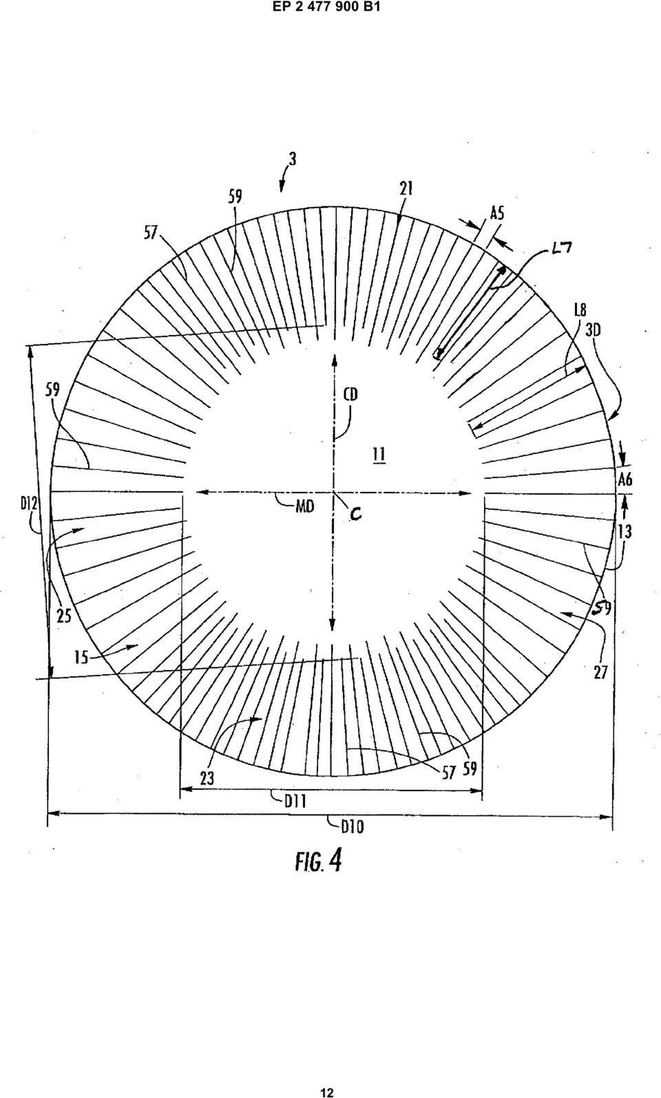
3 3 EP B1 4 the score lines 19. In one embodiment, adjacent score lines 17, 19 are spaced apart by an angle of at least approximately degrees that is uniform around the perimeter of the blank. The central portion 11 can be substantially free of any fold lines, score line, or other line of weakening, without departing from the disclosure. Further, the central portion 11 can have a line of weakening to facilitate forming the blank 3 into the container without departing from the disclosure. [00] All dimensional information presented herein is intended to be illustrative of certain aspects, features, etc., of various embodiments of the disclosure, and is not intended to limit the scope of the disclosure. The dimensions of the blanks, containers, forming tools, features, or any other dimension, can be more or less than what is shown and described in this disclosure without departing from the scope of this disclosure. [0016] As shown in the first embodiment, the blank 3A has a diameter D1 of at least approximately mm (6.687 inches), the central portion 11 has a minimum diameter D2 between respective ends of the score lines 19 of at least approximately 91.1 (3.90) and a maximum diameter D3 between respective ends of the score lines 17 of at least approximately 99.9 mm (3.932 inches). In the embodiment of Fig. 1, the shorter score lines 17 have a length L1 of at least approximately mm (1.377 inches) and the longer score lines 19 have a length L2 of at least approximately mm (1.48 inches), making the minimum radial length of the marginal portion the length L1, and the maximum radial length of the marginal portion the length L2. In the embodiment of Fig. 1, the blank 3 has 72 score lines 17, 19, each respectively spaced apart by an angle A1 of approximately five degrees, but more or less than 72 score lines could be provided and the angle A1 could be more or less than five degrees. [0017] In one embodiment, the score lines 19 are at least about percent longer than the score lines 17, in another embodiment, the score lines 19 can be at least about percent longer than the score lines 17, and in yet another embodiment, the score lines 19 can be at least about 12 percent longer than the score lines 17. [0018] In the embodiment of Fig. 2, which does not form part of the present invention, the blank 3B has a larger diameter D4 than the diameter D1 of blank 3A, the central portion 11 has a minimum diameter D that is the same as the minimum diameter D2 of the blank 3A, and the central portion has a maximum diameter D6 that is the same as the maximum diameter D3 of the blank 3A. The score lines 37, 39 of the blank 3B are longer than the score lines 17, 19 of the blank 3A. In the embodiment of Fig. 2, the blank 3B has a diameter D4 of at least approximately mm (6.937 inches), the score lines 37 have a length L3 of at least approximately mm (1.02 inches), and the score lines 39 have a length L4 of at least approximately mm (1.673 inches). The blank 3B includes 72 score lines 37, 39 at an equal degree angular spacing A2 between adjacent score lines. [0019] In the embodiment of Fig. 3, the blank 3C has a diameter D7 that is equal to the diameter D1 of the blank 3A, the central portion 11 has a minimum diameter D8 that is the same as the minimum diameter D2 of the blank 3A, and the central portion has a maximum diameter D9 that is the same as the maximum diameter D3 of the blank 3A. The marginal portion of the blank 3C includes score lines 47, 49. The score lines 47, 49 have a respective length L, L6 that is equal to the corresponding length L1, L2 of a respective score line 17, 19 of the blank 3A of the first embodiment. In the third embodiment, the blank 3C includes a greater number and different arrangement of the score lines 47, 49. The blank 3C has cross-direction portions 21, 23 of the marginal portion at respective opposite sides of the blanks. The crossdirection portions 21, 23 each includes score lines 47, 49 that are more closely spaced than the previous embodiments. In the embodiment of Fig. 3, each cross-direction portion 21, 23 includes 29 score lines 47, 49 that are spaced apart at an equal 3.21 degree spacing A3 between adjacent score lines. [0020] In the embodiment of Fig. 3, the blank 3C has machine-direction portions 2, 27 of the marginal portion that includes the longer score lines 49 that are spaced apart a greater distance than the spacing of the previous embodiments. The machine-direction portions 2, 29 are free from the shorter score lines 47. In the illustrated embodiment, the score lines 49 in the machine-direction portions 2, 27 of the blank 3C are spaced apart at an equal.71 degree spacing A4 between adjacent score lines. Each of the machine-direction portions 2, 27 includes score lines 49 so that the blank 3C includes a total of 88 score lines ( in each machine direction portion 2, 27 and 29 in each cross-direction portion 21, 23). [0021] In the embodiment of Fig. 4, the blank 3D has a diameter D that is equal to the diameter D2 of the blank 3B of the second embodiment, and the score lines 7, 9 have respective lengths L7, L8 that are the same length as the length L3, L4 of the score lines 37, 39 of the blank 3B of the second embodiment. The central portion 11 has a minimum diameter D that is the same as minimum diameter D2 of the blank 3A, and the central portion has a maximum diameter D11 that is the same as the maximum diameter D3 of the blank 3A. The blank 3D has cross-direction portions 81, 83 and machine-direction portions 8, 87 that are similar to the portions 23, 23 and 2, 27 of the blank 3C of the third embodiment in that the cross-direction portions 81, 83 each include 29 score lines 7, 9, with an equal 3.21 degree spacing A between respective adjacent score lines. The machinedirection portions 8, 87 each include score lines 79, with an equal.71 degree spacing A6 between respective adjacent score lines. [0022] The score lines 17, 19, 37, 39, 47, 49, 7, 9 of the blanks 3A, 3B, 3C, 3D can be otherwise shaped, arranged, and/or configured without departing from the scope of this disclosure. In one embodiment, the blank 3

4 EP B comprises 18 point paperboard having a thickness of approximately (.018") 0.46 mm, but the blank 3 could have a larger or smaller thickness or could comprise other materials. All of the dimensional information presented herein is intended to be illustrative of certain aspects of the disclosure and is not intended to limit the scope of the disclosure, as various other embodiments of the disclosure could include dimensions that are greater than or less than the dimensions included herein. [0023] Figs. -7 show various views of the container formed from a respective one of the blanks 3. The container comprises a generally flat bottom wall 133, a bottom corner 13 that connects the bottom wall to an annular side wall 137, an upper corner 139 that connects the side wall 137 to the flange 7, and an outer radial edge 141. The bottom wall 133 and side wall 137 at least partially define an interior space 14 of the container. The container could be otherwise shaped, arrange, configured, and/or dimensioned without departing from this disclosure. [0024] As shown in Figs. 8 and 9, the forming tool 9 comprises a cavity block 1 that is part of a lower tool assembly 2, and a punch or nose 3 that is part of an upper tool assembly 4. The cavity block 1 has a bottom wall, a lower corner 7 that connects the bottom wall to an annular side wall 9, an upper corner 161 that connects the sidewall to an upper surface 163. The bottom wall, lower corner 7, annular side wall 9, upper corner 161 form a recess 164 in the cavity block 1 below the upper surface 163. The upper surface 163 supports the flange 7 when the punch 3 has been received into the recess 164 of the cavity block 1 to form the blank 3 into the container. The recess 164 and upper surface 163 of the cavity block 1 are generally shaped to correspond with the desired shape of the container. [002] The upper corner 161 is a rounded surface between the flat upper surface 163 and the flat side wall surface 9 that has an increased radius to minimize forces that occur when the blank 3 is pulled over the upper corner of the forming tool 9 during formation of the container from the blank. The upper corner 161 forms the upper corner 139 of the container that connects the flange 7 to the side wall 137. In one embodiment the upper corner 61 has a radius R of at least approximately 1.27 mm (0.0 inches), and preferably at least about 1.6 mm (0.062 inches). [0026] In one embodiment, the blank 3 is formed into the container by conveying a blank in the machine direction MD and placing the blank in the forming tool 9 when the lower tool assembly 2 and upper tool assembly are in a separated or open position. The forming tool 9 is used to press form the blank 3 into the container by moving the tool assemblies 2, 4 together, to a closed position (Figs. 8 and 9), in a manner such that the punch 3 is pressed against the blank 3 to force the blank into the cavity 164 of the cavity block 1. When the flat blank 3 is pressed into the cavity 4 and formed into the threedimensional container by closing the forming tool 9, the score lines 17, 19, 37, 39, 47, 49, and 7, 9 facilitate forming the flat blank into the three-dimensional container in the forming tool 9. The score lines 17, 19, 37, 39 47, 49, 7, and 9 allow formation of the marginal portion of the blank 3 into the side wall 137 and flange 7 of the container. The flange 7 is formed by being pressed between the nose 3 and the flat upper surface 163 of the cavity block 1. The stiffness of the paperboard material of the blanks 3A, 3B, which do not form part of the present invention, is approximately twice as great in the cross-direction areas as the machine-direction areas. Since the paperboard stiffness is generally weaker in the machine-direction, the blanks 3A, 3B can be subjected to twice the elongation in the machine-direction areas as compared to the cross-direction areas when the blanks 3 are press-formed into the container. [0027] The blank 3C has an increased number of score lines 47, 49 in the cross-direction portions 21, 23 of the marginal area of blank 3C and a decreased spacing A3 between the score lines 47, 49 in the cross-direction areas 21, 23. Also, the blank 3C has an increased spacing A4 between the score lines 49 in the machine-direction portions 2, 27. In the illustrated embodiment, each cross-direction area 21, 23 has fourteen first score lines 47 and fifteen second score lines 49, and each machine direction area 2, 27 has fifteen second score lines 49 and zero first score lines 47. Similarly, the blank 3D has an increased number of score lines 7, 9 in the crossdirection portions 81, 83 of the marginal area of the blank 3D and a decreased spacing A between the score lines 7, 9 in the cross-direction areas. Further, the blank 3D has an increased spacing A6 between the score lines 9 in the machine-direction portions 8, 87. The arrangement and positioning of the score lines 47, 49 and 7, 9 in a respective blank 3C, 3D, promotes a uniform width of the flange 7 when the blanks 3C, 3D are formed into the container. The stiffness of the blanks 3C, 3D in the cross-direction portions 21, 23, and 81, 83 is reduced by the increased number and closer spacing of the score lines 47, 49, and 7, 9 so that the crossdirection portions will have increased elongation when the blanks are formed into the container. The stiffness of the blanks 3C, 3D in the machine-direction portions 2, 27, and 8, 87 is increased as compared to the crossdirection portions 21, 23, and 81, 83, because the machine direction portions 2, 27, and 8, 87 have a decreased number and larger spacing of the first score lines 49, 9, so that the machine-direction portions will have decreased elongation as compared to the cross-direction portions when the blanks are formed into the container. [0028] Also, the radius R of the upper corner 161 of the cavity 1 of the forming tool 9 is increased to minimize the creation of bending forces that will occur when the blanks 3 are formed into the container. The forming tool 9 can have other features to facilitate forming of the container from any of the blanks 3A, 3B, 3C, 3D without departing from the scope of this disclosure. 4

5 7 EP B1 8 [0029] In one aspect, for example, any of the blanks 3A, 3B, 3C, 3D can comprise paperboard having a basis weight of from about (60 to about 330 lbs/ream), 27 to about 148 Kg/ream, wherein a ream equals (3,000 ft 2 ) 279 m 2, for example, from (about 80 to about 140 lbs/ream) about 36 Kg/ream to about 63 Kg/ream. The paperboard generally may have a thickness of from about 6 to about 30 mils, for example, from about 0.30 to about 0.71 mm (about 12 to about 28 mils). In one particular example, the paperboard has a thickness of at least about 0.30 mm (12 mils). Any suitable paperboard may be used, for example, a solid bleached or solid unbleached sulfate board, such as SUS board, commercially available from Graphic Packaging International. In another aspect, where a more flexible construct is to be formed, the blank may comprise a paper or paper-based material generally having a basis weight of from (about to about 60 lbs/ream) about 6.7 Kg/ream to about 27 Kg/ream, for example, from about (20 to about 40 lbs/ream) about 9 Kg/ream to about 18 Kg/ream. In one particular example, the paper has a basis weight of (about 2 lbs/ream) about 11 Kg/ream. [0030] Optionally, one or more portions of the blank or other constructs described herein or contemplated hereby may be coated with varnish, clay, or other materials, either alone or in combination. The coating may then be printed over with product advertising or other information or images. The blanks or other constructs also may be selectively coated and/or printed so that less than the entire surface area of the blank or substantially the entire surface area of the blank may be coated and/or printed. [0031] The foregoing description illustrates and describes various embodiments of the present disclosure. As various changes could be made in the above construction without departing from the scope of the disclosure, it is intended that all matter contained in the above description or shown in the accompanying drawings shall be interpreted as illustrative and not in a limiting sense. Furthermore, the scope of the present disclosure covers various modifications, combinations, and alterations, etc., of the above-described embodiments. Additionally, the disclosure shows and describes only selected embodiments, but various other combinations, modifications, and environments are contemplated and are within the scope of the appended claims a central portion (11); an outer edge (13); and a marginal portion () between the outer edge and the central portion, the blank comprising a radius extending from a center (C) of the blank to the outer edge, the marginal portion comprising a plurality of radial score lines (47, 49; 7, 9) having an angular spacing between respective adjacent radial score lines, the plurality of score lines comprising a plurality of first score lines (47; 7) and a plurality of second score lines (49; 9), the first score lines (47; 7) each having a respective first length (L; L7) and the second score lines (49; 9) each having a respective second length (L6; L8), the first length (L; L7) being less than the second length (L6; L8), the blank (3C; 3D) has a first, machine direction (MD), along which the blank may be fed into a forming tool (9), and a cross-direction (CD) that is perpendicular to the first direction (MD), the marginal portion () has a first cross-direction portion (21) at one cross-directional end of the blank, a second cross-direction portion (23) at a second cross-directional end of the blank, a first machine-direction portion (2) at one machine directional end of the blank, and a second machine-direction portion (27) at a second machine-directional end of the blank, characterised in that the blank (3C; 3D) comprises weakening features in each of the first cross-direction portion (21) and the second cross-direction portion (23) and strengthening features in each of the first machine-direction portion (2) and the second machine-direction portion (27), the weakening features and the strengthening features being for strengthened resistance of the blank to stretching in the first machine-direction portion and the second machine-direction portion as compared to the first cross-direction portion and the second cross-direction portion, the weakening features comprise the plurality of first score lines (47; 7) and at least a portion of the plurality second score lines (49; 9), the strengthening features comprise at least a portion of the plurality of second score lines (49; 9), and the strengthening features are free from any of the first score lines (47; 7) in the first machine-direction portion (2) and the second machine-direction portion (27). Claims 1. A blank (3C; 3D) for forming a container (), the blank comprising: 0 2. The blank (3C; 3D) of claim 1 wherein in each of the weakening features each of the plurality of first score lines (47; 7) are adjacent to and spaced apart from a respective one of the second score lines (49; 9) by a first angular spacing (A3; A). 3. The blank (3C; 3D) of claim 2 wherein in each of the strengthening features the second score lines (49; 9) being adjacent to another of the second score lines and being spaced apart from a respective one of the second score line by a second angular spacing (A4; A6), the second angular spacing (A4; A6) being
.")
6 9 EP B1 greater than the first angular spacing (A3; A). 4. The blank (3C; 3D) of claim 1 wherein the first crossdirection portion (21) having the same quantity of first and second score lines (47, 49; 7, 9) as the second cross-direction portion (23).. The blank (3C; 3D) of claim 4 wherein the first machine-direction portion (2) has the same quantity of second score lines (49; 9) as the second machinedirection portion (27; 87). 6. The blank (3C; 3D) of claim 1 wherein the combined quantity of first and second score lines (47, 49; 7, 9) in each of the first and second cross-direction portion (21, 23) is greater than the quantity of second score lines (49; 9) in each machine-direction portion (2,27). 7. The blank (3C; 3D) of claim 1 wherein each of the first score line (47; 7) and the second score line (49; 9) extend from the outer edge (13) of the blank to a location adjacent the central portion (11) of the blank. 8. A container () formed from the blank (3C; 3D) of claim 7, the container comprising: a bottom wall (133) formed from the central portion (11); a side wall (137) extending upwardly from the bottom wall (133) and being formed from at least a portion of the marginal portion () of the blank; and a flange (7) extending laterally outward from the side wall (137) and being formed from at least a portion of the marginal portion () of the blank. 9. The container () of claim 8 wherein bottom wall (133) is generally circular and the container is a tray with the top surface of the flange (7) corresponding to a top surface of the tray.. The container () of claim 8 further comprising an upper corner (139) that connects the side wall (137) to the flange (7), the upper corner being a curved portion of the container that extends between respective flat surfaces of the flange (7) and the side wall (137). Patentansprüche 1. Zuschnitt (3C; 3D) zum Ausbilden eines Behälters (), wobei der Zuschnitt umfasst: einen zentralen Abschnitt (11); eine Außenkante (13); und einen Randabschnitt () zwischen der Außenkante und dem zentralen Abschnitt, wobei der Zuschnitt einen Radius umfasst, welcher sich von einer Mitte (C) des Zuschnitts zur Außenkante erstreckt, wobei ein Randabschnitt eine Mehrzahl von radialen Kerblinien (47, 49; 7, 9) mit einem winkeligen Abstand zwischen jeweilig benachbarten Kerblinien aufweist, wobei die Mehrzahl von Kerblinien eine Mehrzahl von ersten Kerblinien (47; 7) und eine Mehrzahl von zweiten Kerblinien (49; 9) aufweist, wobei die ersten Kerblinien (47; 7) jeweils eine erste Länge (L; L7) aufweisen und die zweiten Kerblinien (49; 9) jeweils eine zweite Länge (L6; L8) aufweisen, wobei die erste Länge (L; L7) kürzer ist als die zweite Länge (L6; L8), wobei der Zuschnitt (3C; 3D) eine erste Maschinenrichtung (MD), entlang welcher der Zuschnitt in ein Ausformungswerkzeug (9) zugeführt werden kann, und eine Querrichtung (CD), welche senkrecht zur ersten Richtung (MD) steht, aufweist, wobei der Randabschnitt () einen ersten Querrichtungsabschnitt (21) an einem Querrichtungsende des Zuschnitts, einen zweiten Querrichtungsabschnitt (23) an einem zweiten Querrichtungsende des Zuschnitts, einen ersten Maschinenrichtungsabschnitt (2) an einem Maschinenrichtungsende des Zuschnitts und einen zweiten Maschinenrichtungsabschnitt (27) an einem Maschinenrichtungsende des Zuschnitts umfasst, dadurch gekennzeichnet, dass der Zuschnitt (3C; 3D) Schwächungsmerkmale sowohl im ersten Querrichtungsabschnitt (21) als auch im zweiten Querrichtungsabschnitt (23) und Verstärkungsmerkmale sowohl im ersten Maschinenrichtungsabschnitt (2) als auch im zweiten Maschinenrichtungsabschnitt (27) aufweist, wobei die Schwächungsmerkmale und die Verstärkungsmerkmale zur verstärkten Widerstandskraft des Zuschnitts gegen Dehnung im ersten Maschinenrichtungsabschnitt und im zweiten Maschinenrichtungsabschnitt im Vergleich zum ersten Querrichtungsabschnitt und zum zweiten Querrichtungsabschnitt dienen, wobei die Schwächungsmerkmale die Mehrzahl der ersten Kerblinien (47; 7) und wenigstens einen Abschnitt der Mehrzahl der zweiten Kerblinien (49; 9) umfassen, wobei die Verstärkungsmerkmale wenigstens einen Abschnitt der Mehrzahl der zweiten Kerblinien (49; 9) umfassen und die Verstärkungsmerkmale frei von ersten Kerblinien (47; 7) im ersten Maschinenrichtungsabschnitt (2) und im zweiten Maschinenrichtungsabschnitt (27) sind. 2. Zuschnitt (3C; 3D) nach Anspruch 1, wobei in jedem 6
 of claim 4 wherein the first machine-direction portion (2) has the same quantity of second score lines (49; 9) as the second machinedirection portion (27; 87). 6.")
7 11 EP B1 12 der Schwächungsmerkmale jede der Mehrzahl von ersten Kerblinien (47; 7) benachbart einer jeweiligen der zweiten Kerblinien (49; 9) und zu dieser durch einen ersten winkeligen Abstand (A3; A) beabstandet ist. 3. Zuschnitt (3C; 3D) nach Anspruch 2, wobei in jedem der Verstärkungsmerkmale die zweiten Kerblinien (49; 9) benachbart einer jeweiligen weiteren der zweiten Kerblinien und zu dieser durch einen zweiten winkeligen Abstand (A4; A6) beabstandet sind, wobei der zweite winkelige Abstand (A4; A6) größer ist als der erste winkelige Abstand (A3; A). 4. Zuschnitt (3C; 3D) nach Anspruch 1, wobei der erste Querrichtungsabschnitt (21) die gleiche Anzahl an ersten und zweiten Kerblinien (47, 49; 7, 9) aufweist wie der zweite Querrichtungsabschnitt (23).. Zuschnitt (3C; 3D) nach Anspruch 4, wobei der erste Maschinenrichtungsabschnitt (2) die gleiche Anzahl an ersten und zweiten Kerblinien (49; 9) aufweist wie der zweite Maschinenrichtungsabschnitt (27; 87). 6. Zuschnitt (3C; 3D) nach Anspruch 1, wobei die kombinierte Anzahl an ersten und zweiten Kerblinien (47, 49; 7, 9) in jedem von erstem und zweiten Querrichtungsabschnitt (21, 23) größer ist als die Anzahl der zweiten Kerblinien (49; 9) in jedem Maschinenrichtungsabschnitt (2, 27). 7. Zuschnitt (3C; 3D) nach Anspruch 1, wobei jede der ersten Kerblinien (47; 7) und der zweiten Kerblinien (49; 9) sich von der Außenkante (13) des Zuschnitts zu einer Stelle benachbart dem zentralen Abschnitt (11) des Zuschnitts erstreckt. 8. Behälter (), welcher aus dem Zuschnitt (3C; 3D) nach Anspruch 7 ausgebildet wird, wobei der Behälter umfasst: eine Bodenwand (133), welche aus dem zentralen Abschnitt (11) ausgebildet ist; eine Seitenwand (137), welche sich nach oben von der Bodenwand (133) aus erstreckt und aus wenigstens einem Abschnitt des Randabschnitts () des Zuschnitts gebildet wird; und einen Flansch (7), welcher sich seitlich nach außen von der Seitenwand (137) aus erstreckt und aus wenigstens einem Abschnitt des Randabschnitts () des Zuschnitts ausgebildet ist. 9. Behälter () nach Anspruch 8, wobei die Bodenwand (133) allgemein rund ist und der Behälter eine Schale mit einer oberen Oberfläche des Flansches (7) ist, welche einer oberen Oberfläche der Schale entspricht.. Behälter () nach Anspruch 8, des Weiteren umfassend eine obere Kante (139), welche die Seitenwand (137) mit dem Flansch (7) verbindet, wobei die obere Kante ein gebogener Abschnitt des Behälters ist, der sich zwischen jeweiligen ebenen Oberflächen des Flansches (7) und der Seitenwand (137) erstreckt. Revendications 1. Découpe (3C ; 3D) destinée à former un conteneur (), la découpe comprenant : une partie centrale (11) ; un bord extérieur (13) ; et une partie de bord () entre le bord extérieur et la partie centrale, la découpe comprenant un rayon s étendant à partir d un centre (C) de la découpe vers le bord extérieur, la partie de bord comprenant une pluralité de lignes de rainage radiales (47, 49 ; 7, 9) présentant un espacement angulaire entre les lignes de rainage adjacentes respectives, la pluralité de lignes de rainage comprenant une pluralité de premières lignes de rainage (47 ; 7) et une pluralité de deuxièmes lignes de rainage (49 ; 9), les premières lignes de rainage (47 ; 7) présentant chacune une première longueur respective (L ; L7) et les deuxièmes lignes de rainage (49 ; 9) présentant chacune une deuxième longueur respective (L6 ; L8), la première longueur (L ; L7) étant inférieure à la deuxième longueur (L6 ; L8), la découpe (3C ; 3D) présente une première direction de machine (MD), le long de laquelle la découpe peut être alimentée vers un outil de formage (9), et une direction transversale (CD) perpendiculaire à la première direction (MD), la partie de bord () présentant une première partie transversale (21) à une extrémité transversale de la découpe, une deuxième partie transversale (23) à une deuxième extrémité transversale de la découpe, une première partie s étendant dans la direction de machine (2) à une extrémité de direction de machine de la découpe, et une deuxième partie s étendant dans la direction de machine (27) à une deuxième extrémité de direction de machine de la découpe, caractérisée en ce que la découpe (3C ; 3D) comprend des éléments d affaiblissement dans chacune parmi la première partie transversale (21) et la deuxième partie transversale (23), et des éléments de renfort dans chacune parmi la première partie s étendant dans la direction de machine (2) et 7
 beabstandet sind, wobei der zweite winkelige Abstand (A4; A6) größer ist als der erste winkelige Abstand (A3; A). 4.")
8 13 EP B1 14 la deuxième partie s étendant dans la direction de machine (27), les éléments d affaiblissement et les éléments de renfort étant destinés à augmenter la résistance de la découpe à l étirement dans la première partie s étendant dans la direction de machine et la deuxième partie s étendant dans la direction de machine en comparaison avec la première partie transversale et la deuxième partie transversale, les éléments d affaiblissement comprennent la pluralité de premières lignes de rainage (47 ; 7) et au moins une partie de la pluralité de deuxièmes lignes de rainage (49 ; 9), les éléments de renfort comprennent au moins une partie de la pluralité de deuxièmes lignes de rainage (49 ; 9), et les éléments de renfort sont exempts de n importe laquelle des premières lignes de rainage (47 ; 7) dans la première partie s étendant dans la direction de machine (2) et la deuxième partie s étendant dans la direction de machine (27). 2. Découpe (3C ; 3D) selon la revendication 1, dans laquelle, dans chacun des éléments d affaiblissement, chacune parmi la pluralité de premières lignes de rainage (47 ; 7) est adjacente à l une respective parmi les deuxièmes lignes de rainage (49 ; 9) et espacée de celle-ci selon un premier espacement angulaire (A3 ; A). 3. Découpe (3C ; 3D) selon la revendication 2, dans laquelle, dans chacun des éléments de renfort, les deuxièmes lignes de rainage (49 ; 9) sont adjacentes à une autre parmi les deuxièmes lignes de rainage et espacées de l une respective parmi les deuxièmes lignes de rainage, selon un deuxième espacement angulaire (A4 ; A6), le deuxième espacement angulaire (A4 ; A6) étant supérieur au premier espacement angulaire (A3 ; A). 4. Découpe (3C ; 3D) selon la revendication 1, dans laquelle la première partie transversale (21) présente la même quantité de premières et de deuxièmes lignes de rainage (47, 49 ; 7, 9) que la deuxième partie transversale (23) rainage (49 ; 9) dans chaque partie s étendant dans la direction de machine (2, 27). 7. Découpe (3C ; 3D) selon la revendication 1, dans laquelle chacune parmi les premières lignes de rainage (47 ; 7) et les deuxièmes lignes de rainage (49 ; 9) s étend à partir du bord extérieur (13) de la découpe, jusqu à un point adjacent à la partie centrale (11) de la découpe. 8. Conteneur () formé à partir de la découpe (3C ; 3D) de la revendication 7, le conteneur comprenant : une paroi inférieure (133) formée à partir de la partie centrale (11) ; une paroi latérale (137) s étendant vers le haut à partir de la paroi inférieure (133), tout en étant formée à partir d au moins une partie de la partie de bord () de la découpe ; et un rebord (7) s étendant latéralement vers l extérieur à partir de la paroi latérale (137), tout en étant formée à partir d au moins une partie de la partie de bord () de la découpe. 9. Conteneur () selon la revendication 8, dans lequel la paroi inférieure (133) est généralement circulaire et le conteneur est un plateau, avec la surface supérieure du rebord (7) correspondant à une surface supérieure du plateau.. Conteneur () selon la revendication 8, comprenant en outre un coin supérieur (139) reliant la paroi latérale (137) au rebord (7), le coin supérieur étant une partie courbe du conteneur, laquelle s étend entre des surfaces planes respectives du rebord (7) et de la paroi latérale (137).. Découpe (3C ; 3D) selon la revendication 4, dans laquelle la première partie s étendant dans la direction de machine (2) présente la même quantité de deuxièmes lignes de rainage (49 ; 9) que la deuxième partie s étendant dans la direction de machine (27 ; 87) Découpe (3C ; 3D) selon la revendication 1, dans laquelle la somme des premières et deuxièmes lignes de rainage (47, 49 ; 7, 9) dans chacune des première et deuxième parties transversales (21, 23) est supérieure à la quantité de deuxièmes lignes de 8
, les éléments de renfort comprennent au moins une partie de la pluralité de deuxièmes lignes de rainage (49 ; 9), et les éléments de renfort sont exempts de n importe laquelle des premières")
9 EP B1 9

10 EP B1

11 EP B1 11

12 EP B1 12
13 EP B1 13

14 EP B1 14

15 EP B1 REFERENCES CITED IN THE DESCRIPTION This list of references cited by the applicant is for the reader s convenience only. It does not form part of the European patent document. Even though great care has been taken in compiling the references, errors or omissions cannot be excluded and the EPO disclaims all liability in this regard. Patent documents cited in the description US A [0007] US A [0011] WO A [0011] US A [0012]

*EP001173363B1* EP 1 173 363 B1 (19) (11) EP 1 173 363 B1 (12) EUROPEAN PATENT SPECIFICATION
 (11) EP 1 173 363 B1 (12) EUROPEAN PATENT SPECIFICATION") (19) Europäisches Patentamt European Patent Office Office européen des brevets *EP001173363B1* (11) EP 1 173 363 B1 (12) EUROPEAN PATENT SPECIFICATION (4) Date of publication and mention of the grant of
(19) Europäisches Patentamt European Patent Office Office européen des brevets *EP001173363B1* (11) EP 1 173 363 B1 (12) EUROPEAN PATENT SPECIFICATION (4) Date of publication and mention of the grant of
(51) Int Cl.: B29C 41/20 (2006.01) F21S 4/00 (2006.01) H05K 3/28 (2006.01)
 Int Cl.: B29C 41/20 (2006.01) F21S 4/00 (2006.01) H05K 3/28 (2006.01)") (19) TEPZZ 68698B_T (11) EP 2 68 698 B1 (12) EUROPEAN PATENT SPECIFICATION (4) Date of publication and mention of the grant of the patent: 18.11.201 Bulletin 201/47 (21) Application number: 11808612.3
(19) TEPZZ 68698B_T (11) EP 2 68 698 B1 (12) EUROPEAN PATENT SPECIFICATION (4) Date of publication and mention of the grant of the patent: 18.11.201 Bulletin 201/47 (21) Application number: 11808612.3
(51) Int Cl.: H04N 5/225 (2006.01)
 Int Cl.: H04N 5/225 (2006.01)") (19) TEPZZ_94 66_B_T (11) EP 1 942 661 B1 (12) EUROPEAN PATENT SPECIFICATION (4) Date of publication and mention of the grant of the patent: 17.09.2014 Bulletin 2014/38 (1) Int Cl.: H04N /22 (2006.01)
(19) TEPZZ_94 66_B_T (11) EP 1 942 661 B1 (12) EUROPEAN PATENT SPECIFICATION (4) Date of publication and mention of the grant of the patent: 17.09.2014 Bulletin 2014/38 (1) Int Cl.: H04N /22 (2006.01)
(51) Int Cl.: H04L 29/06 (2006.01) G06F 9/445 (2006.01) G06F 13/00 (2006.01)
 Int Cl.: H04L 29/06 (2006.01) G06F 9/445 (2006.01) G06F 13/00 (2006.01)") (19) TEPZZ_7486_6B_T (11) EP 1 748 616 B1 (12) EUROPEAN PATENT SPECIFICATION (4) Date of publication and mention of the grant of the patent: 03.09.2014 Bulletin 2014/36 (1) Int Cl.: H04L 29/06 (2006.01)
(19) TEPZZ_7486_6B_T (11) EP 1 748 616 B1 (12) EUROPEAN PATENT SPECIFICATION (4) Date of publication and mention of the grant of the patent: 03.09.2014 Bulletin 2014/36 (1) Int Cl.: H04L 29/06 (2006.01)
(51) Int Cl.: G06F 9/455 (2006.01) G06F 9/50 (2006.01)
 Int Cl.: G06F 9/455 (2006.01) G06F 9/50 (2006.01)") (19) TEPZZ 6987 B_T (11) EP 2 698 711 B1 (12) EUROPEAN PATENT SPECIFICATION (4) Date of publication and mention of the grant of the patent: 0.08.1 Bulletin 1/32 (21) Application number: 118777.8 (22) Date
(19) TEPZZ 6987 B_T (11) EP 2 698 711 B1 (12) EUROPEAN PATENT SPECIFICATION (4) Date of publication and mention of the grant of the patent: 0.08.1 Bulletin 1/32 (21) Application number: 118777.8 (22) Date
(51) Int Cl.: C08K 5/523 (2006.01) C08K 5/521 (2006.01) C08K 5/52 (2006.01) C08G 64/00 (2006.01)
 Int Cl.: C08K 5/523 (2006.01) C08K 5/521 (2006.01) C08K 5/52 (2006.01) C08G 64/00 (2006.01)") (19) Europäisches Patentamt European Patent Office Office européen des brevets (11) EP 0 78 966 B1 (12) EUROPEAN PATENT SPECIFICATION (4) Date of publication and mention of the grant of the patent: 01.03.06
(19) Europäisches Patentamt European Patent Office Office européen des brevets (11) EP 0 78 966 B1 (12) EUROPEAN PATENT SPECIFICATION (4) Date of publication and mention of the grant of the patent: 01.03.06
TEPZZ_768 7_B_T EP 1 768 371 B1 (19) (11) EP 1 768 371 B1 (12) EUROPEAN PATENT SPECIFICATION. (51) Int Cl.: H04M 19/04 (2006.01)
 (11) EP 1 768 371 B1 (12) EUROPEAN PATENT SPECIFICATION. (51) Int Cl.: H04M 19/04 (2006.01)") (19) TEPZZ_768 7_B_T (11) EP 1 768 371 B1 (12) EUROPEAN PATENT SPECIFICATION (4) Date of publication and mention of the grant of the patent: 1.01.2014 Bulletin 2014/03 (1) Int Cl.: H04M 19/04 (2006.01)
(19) TEPZZ_768 7_B_T (11) EP 1 768 371 B1 (12) EUROPEAN PATENT SPECIFICATION (4) Date of publication and mention of the grant of the patent: 1.01.2014 Bulletin 2014/03 (1) Int Cl.: H04M 19/04 (2006.01)
(51) Int Cl.: G05F 3/26 (2006.01) G05F 3/24 (2006.01)
 Int Cl.: G05F 3/26 (2006.01) G05F 3/24 (2006.01)") (19) Europäisches Patentamt European Patent Office Office européen des brevets (11) EP 1 280 033 B1 (12) EUROPEAN PATENT SPECIFICATION (4) Date of publication and mention of the grant of the patent: 31.0.2006
(19) Europäisches Patentamt European Patent Office Office européen des brevets (11) EP 1 280 033 B1 (12) EUROPEAN PATENT SPECIFICATION (4) Date of publication and mention of the grant of the patent: 31.0.2006
The Advantialer and Its Advantages
 (19) TEPZZ Z B_T (11) EP 2 0 113 B1 (12) EUROPEAN PATENT SPECIFICATION (4) Date of publication and mention of the grant of the patent: 16.09.1 Bulletin 1/38 (21) Application number: 07809477.8 (22) Date
(51) Int Cl.: H05K 1/02 (2006.01)
 Int Cl.: H05K 1/02 (2006.01)") (19) (11) EP 1 229 767 B1 (12) EUROPEAN PATENT SPECIFICATION (4) Date of publication and mention of the grant of the patent: 20.01.2010 Bulletin 2010/03 (1) Int Cl.: H0K 1/02 (2006.01) (21) Application
(19) (11) EP 1 229 767 B1 (12) EUROPEAN PATENT SPECIFICATION (4) Date of publication and mention of the grant of the patent: 20.01.2010 Bulletin 2010/03 (1) Int Cl.: H0K 1/02 (2006.01) (21) Application
TEPZZ 87_546A T EP 2 871 546 A2 (19) (11) EP 2 871 546 A2 (12) EUROPEAN PATENT APPLICATION. (51) Int Cl.: G05B 19/05 (2006.01)
 (11) EP 2 871 546 A2 (12) EUROPEAN PATENT APPLICATION. (51) Int Cl.: G05B 19/05 (2006.01)") (19) TEPZZ 87_46A T (11) EP 2 871 46 A2 (12) EUROPEAN PATENT APPLICATION (43) Date of publication: 13.0.1 Bulletin 1/ (1) Int Cl.: G0B 19/0 (06.01) (21) Application number: 14188238.1 (22) Date of filing:
(19) TEPZZ 87_46A T (11) EP 2 871 46 A2 (12) EUROPEAN PATENT APPLICATION (43) Date of publication: 13.0.1 Bulletin 1/ (1) Int Cl.: G0B 19/0 (06.01) (21) Application number: 14188238.1 (22) Date of filing:
(51) Int Cl. 7 : G03G 15/00
 Int Cl. 7 : G03G 15/00") (19) Europäisches Patentamt European Patent Office Office européen des brevets *EP001179B1* (11) EP 1 17 9 B1 (12) EUROPEAN PATENT SPECIFICATION (4) Date of publication and mention of the grant of the
(19) Europäisches Patentamt European Patent Office Office européen des brevets *EP001179B1* (11) EP 1 17 9 B1 (12) EUROPEAN PATENT SPECIFICATION (4) Date of publication and mention of the grant of the
(51) Int Cl.: G06F 13/38 (2006.01) G06F 1/16 (2006.01)
 Int Cl.: G06F 13/38 (2006.01) G06F 1/16 (2006.01)") (19) TEPZZ 9777B_T (11) EP 2 97 77 B1 (12) EUROPEAN PATENT SPECIFICATION (4) Date of publication and mention of the grant of the patent: 1.07.1 Bulletin 1/29 (1) Int Cl.: G06F 13/38 (06.01) G06F 1/16 (06.01)
(19) TEPZZ 9777B_T (11) EP 2 97 77 B1 (12) EUROPEAN PATENT SPECIFICATION (4) Date of publication and mention of the grant of the patent: 1.07.1 Bulletin 1/29 (1) Int Cl.: G06F 13/38 (06.01) G06F 1/16 (06.01)
*EP001520563A1* EP 1 520 563 A1 (19) (11) EP 1 520 563 A1 (12) EUROPEAN PATENT APPLICATION. (43) Date of publication: 06.04.2005 Bulletin 2005/14
 (11) EP 1 520 563 A1 (12) EUROPEAN PATENT APPLICATION. (43) Date of publication: 06.04.2005 Bulletin 2005/14") (19) Europäisches Patentamt European Patent Office Office européen des brevets *EP001520563A1* (11) EP 1 520 563 A1 (12) EUROPEAN PATENT APPLICATION (43) Date of publication: 06.04.2005 Bulletin 2005/14
(19) Europäisches Patentamt European Patent Office Office européen des brevets *EP001520563A1* (11) EP 1 520 563 A1 (12) EUROPEAN PATENT APPLICATION (43) Date of publication: 06.04.2005 Bulletin 2005/14
TEPZZ 69 _ZA T EP 2 692 310 A2 (19) (11) EP 2 692 310 A2. (12) EUROPEAN PATENT APPLICATION published in accordance with Art.
 (11) EP 2 692 310 A2. (12) EUROPEAN PATENT APPLICATION published in accordance with Art.") (19) TEPZZ 69 _ZA T (11) EP 2 692 3 A2 (12) EUROPEAN PATENT APPLICATION published in accordance with Art. 13(4) EPC (43) Date of publication: 0.02.14 Bulletin 14/06 (21) Application number: 1276632.0 (22)
(19) TEPZZ 69 _ZA T (11) EP 2 692 3 A2 (12) EUROPEAN PATENT APPLICATION published in accordance with Art. 13(4) EPC (43) Date of publication: 0.02.14 Bulletin 14/06 (21) Application number: 1276632.0 (22)
(51) Int Cl.: H04N 1/19 (2006.01) H04N 3/15 (2006.01) H04N 9/04 (2006.01)
 Int Cl.: H04N 1/19 (2006.01) H04N 3/15 (2006.01) H04N 9/04 (2006.01)") (19) (12) EUROPEAN PATENT SPECIFICATION (11) EP 1 417 829 B1 (45) Date of publication and mention of the grant of the patent: 08.04.2009 Bulletin 2009/15 (21) Application number: 02751534.5 (22) Date of
(19) (12) EUROPEAN PATENT SPECIFICATION (11) EP 1 417 829 B1 (45) Date of publication and mention of the grant of the patent: 08.04.2009 Bulletin 2009/15 (21) Application number: 02751534.5 (22) Date of
(51) Int Cl.: G06F 11/20 (2006.01)
 Int Cl.: G06F 11/20 (2006.01)") (19) TEPZZ 66_ B_T (11) EP 2 366 13 B1 (12) EUROPEAN PATENT SPECIFICATION (4) Date of publication and mention of the grant of the patent: 13.0.201 Bulletin 201/20 (21) Application number: 08878183.6 (22)
(19) TEPZZ 66_ B_T (11) EP 2 366 13 B1 (12) EUROPEAN PATENT SPECIFICATION (4) Date of publication and mention of the grant of the patent: 13.0.201 Bulletin 201/20 (21) Application number: 08878183.6 (22)
(51) Int Cl.: H04L 9/24 (2006.01) G06Q 10/00 (2012.01)
 Int Cl.: H04L 9/24 (2006.01) G06Q 10/00 (2012.01)") (19) TEPZZ_4Z 68ZB_T (11) EP 1 2 680 B1 (12) EUROPEAN PATENT SPECIFICATION (4) Date of publication and mention of the grant of the patent: 01.04.1 Bulletin 1/14 (21) Application number: 02741722.9 (22)
(19) TEPZZ_4Z 68ZB_T (11) EP 1 2 680 B1 (12) EUROPEAN PATENT SPECIFICATION (4) Date of publication and mention of the grant of the patent: 01.04.1 Bulletin 1/14 (21) Application number: 02741722.9 (22)
(51) Int Cl.: G06F 21/00 (2006.01) H04L 29/06 (2006.01)
 Int Cl.: G06F 21/00 (2006.01) H04L 29/06 (2006.01)") (19) TEPZZ_8Z_7 _B_T (11) EP 1 801 721 B1 (12) EUROPEAN PATENT SPECIFICATION (4) Date of publication and mention of the grant of the patent: 16.06. Bulletin /24 (1) Int Cl.: G06F 21/00 (06.01) H04L 29/06
(19) TEPZZ_8Z_7 _B_T (11) EP 1 801 721 B1 (12) EUROPEAN PATENT SPECIFICATION (4) Date of publication and mention of the grant of the patent: 16.06. Bulletin /24 (1) Int Cl.: G06F 21/00 (06.01) H04L 29/06
TEPZZ 65Z79 A_T EP 2 650 793 A1 (19) (11) EP 2 650 793 A1. (12) EUROPEAN PATENT APPLICATION published in accordance with Art.
 (11) EP 2 650 793 A1. (12) EUROPEAN PATENT APPLICATION published in accordance with Art.") (19) TEPZZ 65Z79 A_T (11) EP 2 650 793 A1 (12) EUROPEAN PATENT APPLICATION published in accordance with Art. 153(4) EPC (43) Date of publication: 16.10.2013 Bulletin 2013/42 (21) Application number: 12818771.3
(19) TEPZZ 65Z79 A_T (11) EP 2 650 793 A1 (12) EUROPEAN PATENT APPLICATION published in accordance with Art. 153(4) EPC (43) Date of publication: 16.10.2013 Bulletin 2013/42 (21) Application number: 12818771.3
TEPZZ 6_Z76 A_T EP 2 610 763 A1 (19) (11) EP 2 610 763 A1 (12) EUROPEAN PATENT APPLICATION. (51) Int Cl.:
 (11) EP 2 610 763 A1 (12) EUROPEAN PATENT APPLICATION. (51) Int Cl.:") (19) TEPZZ 6_Z76 A_T (11) EP 2 6 763 A1 (12) EUROPEAN PATENT APPLICATION (43) Date of publication: 03.07.2013 Bulletin 2013/27 (51) Int Cl.: G06F 17/30 (2006.01) (21) Application number: 12192220.7 (22)
(19) TEPZZ 6_Z76 A_T (11) EP 2 6 763 A1 (12) EUROPEAN PATENT APPLICATION (43) Date of publication: 03.07.2013 Bulletin 2013/27 (51) Int Cl.: G06F 17/30 (2006.01) (21) Application number: 12192220.7 (22)
(51) Int Cl.: G10L 15/26 (2006.01)
 Int Cl.: G10L 15/26 (2006.01)") (19) TEPZZ Z 8B_T (11) EP 2 023 338 B1 (12) EUROPEAN PATENT SPECIFICATION (4) Date of publication and mention of the grant of the patent: 28.0.14 Bulletin 14/22 (1) Int Cl.: GL /26 (06.01) (21) Application
(19) TEPZZ Z 8B_T (11) EP 2 023 338 B1 (12) EUROPEAN PATENT SPECIFICATION (4) Date of publication and mention of the grant of the patent: 28.0.14 Bulletin 14/22 (1) Int Cl.: GL /26 (06.01) (21) Application
(51) Int Cl.: H04L 12/46 (2006.01) H04L 29/14 (2006.01) H04L 29/12 (2006.01)
 Int Cl.: H04L 12/46 (2006.01) H04L 29/14 (2006.01) H04L 29/12 (2006.01)") (19) (11) EP 1 342 344 B1 (12) EUROPEAN PATENT SPECIFICATION (4) Date of publication and mention of the grant of the patent: 03.06.09 Bulletin 09/23 (21) Application number: 019639.0 (22) Date of filing:.08.01
(19) (11) EP 1 342 344 B1 (12) EUROPEAN PATENT SPECIFICATION (4) Date of publication and mention of the grant of the patent: 03.06.09 Bulletin 09/23 (21) Application number: 019639.0 (22) Date of filing:.08.01
TEPZZ 9 Z5A_T EP 2 922 305 A1 (19) (11) EP 2 922 305 A1. (12) EUROPEAN PATENT APPLICATION published in accordance with Art.
 (11) EP 2 922 305 A1. (12) EUROPEAN PATENT APPLICATION published in accordance with Art.") (19) TEPZZ 9 ZA_T (11) EP 2 922 A1 (12) EUROPEAN PATENT APPLICATION published in accordance with Art. 13(4) EPC (43) Date of publication: 23.09.1 Bulletin 1/39 (21) Application number: 1386446.2 (22) Date
(19) TEPZZ 9 ZA_T (11) EP 2 922 A1 (12) EUROPEAN PATENT APPLICATION published in accordance with Art. 13(4) EPC (43) Date of publication: 23.09.1 Bulletin 1/39 (21) Application number: 1386446.2 (22) Date
(51) Int Cl.: H04W 4/14 (2009.01)
 Int Cl.: H04W 4/14 (2009.01)") (19) (12) EUROPEAN PATENT SPECIFICATION (11) EP 2 184 897 B1 (4) Date of publication and mention of the grant of the patent: 14.03.12 Bulletin 12/11 (21) Application number: 087774.3 (22) Date of filing:
(19) (12) EUROPEAN PATENT SPECIFICATION (11) EP 2 184 897 B1 (4) Date of publication and mention of the grant of the patent: 14.03.12 Bulletin 12/11 (21) Application number: 087774.3 (22) Date of filing:
Office europeen des brevets Publication number: 0 377 486 B1 EUROPEAN PATENT SPECIFICATION
 Office europeen des brevets Publication number: 0 377 486 B1 EUROPEAN PATENT SPECIFICATION Date of publication of patent specification : Int. CI.5 : F16L 58/10, F16L 55/16 21.07.93 Bulletin 93/29 Application
EP 2 455 926 A1 (19) (11) EP 2 455 926 A1 (12) EUROPEAN PATENT APPLICATION. (43) Date of publication: 23.05.2012 Bulletin 2012/21
 (11) EP 2 455 926 A1 (12) EUROPEAN PATENT APPLICATION. (43) Date of publication: 23.05.2012 Bulletin 2012/21") (19) (12) EUROPEAN PATENT APPLICATION (11) EP 2 4 926 A1 (43) Date of publication: 23.0.2012 Bulletin 2012/21 (21) Application number: 11190024.7 (1) Int Cl.: G08B 2/14 (2006.01) G08B 2/00 (2006.01) G0B
(19) (12) EUROPEAN PATENT APPLICATION (11) EP 2 4 926 A1 (43) Date of publication: 23.0.2012 Bulletin 2012/21 (21) Application number: 11190024.7 (1) Int Cl.: G08B 2/14 (2006.01) G08B 2/00 (2006.01) G0B
TEPZZ 46699B_T EP 2 346 699 B1 (19) (11) EP 2 346 699 B1 (12) EUROPEAN PATENT SPECIFICATION
 (11) EP 2 346 699 B1 (12) EUROPEAN PATENT SPECIFICATION") (19) TEPZZ 46699B_T (11) EP 2 346 699 B1 (12) EUROPEAN PATENT SPECIFICATION (4) Date of publication and mention of the grant of the patent: 29.01.14 Bulletin 14/0 (21) Application number: 098101.9 (22)
(19) TEPZZ 46699B_T (11) EP 2 346 699 B1 (12) EUROPEAN PATENT SPECIFICATION (4) Date of publication and mention of the grant of the patent: 29.01.14 Bulletin 14/0 (21) Application number: 098101.9 (22)
(51) Int Cl.: G06F 1/00 (2006.01)
 Int Cl.: G06F 1/00 (2006.01)") (19) (11) EP 0 972 234 B1 (12) EUROPEAN PATENT SPECIFICATION (4) Date of publication and mention of the grant of the patent: 0.09.07 Bulletin 07/36 (21) Application number: 98913219.6 (22) Date of filing:
(19) (11) EP 0 972 234 B1 (12) EUROPEAN PATENT SPECIFICATION (4) Date of publication and mention of the grant of the patent: 0.09.07 Bulletin 07/36 (21) Application number: 98913219.6 (22) Date of filing:
(51) Int Cl.: H04M 3/50 (2006.01)
 Int Cl.: H04M 3/50 (2006.01)") (19) TEPZZ_Z48_64B_T (11) EP 1 048 164 B1 (12) EUROPEAN PATENT SPECIFICATION (4) Date of publication and mention of the grant of the patent: 07.01.1 Bulletin 1/02 (21) Application number: 9893133.0 (22)
(19) TEPZZ_Z48_64B_T (11) EP 1 048 164 B1 (12) EUROPEAN PATENT SPECIFICATION (4) Date of publication and mention of the grant of the patent: 07.01.1 Bulletin 1/02 (21) Application number: 9893133.0 (22)
TEPZZ 68575_A_T EP 2 685 751 A1 (19) (11) EP 2 685 751 A1. (12) EUROPEAN PATENT APPLICATION published in accordance with Art.
 (11) EP 2 685 751 A1. (12) EUROPEAN PATENT APPLICATION published in accordance with Art.") (19) TEPZZ 687_A_T (11) EP 2 68 71 A1 (12) EUROPEAN PATENT APPLICATION published in accordance with Art. 3(4) EPC (43) Date of publication:.01.14 Bulletin 14/03 (21) Application number: 1278849.6 (22)
(19) TEPZZ 687_A_T (11) EP 2 68 71 A1 (12) EUROPEAN PATENT APPLICATION published in accordance with Art. 3(4) EPC (43) Date of publication:.01.14 Bulletin 14/03 (21) Application number: 1278849.6 (22)
Title (fr) SOURCE IONIQUE INTERNE DOUBLE POUR PRODUCTION DE FAISCEAU DE PARTICULES AVEC UN CYCLOTRON
 SOURCE IONIQUE INTERNE DOUBLE POUR PRODUCTION DE FAISCEAU DE PARTICULES AVEC UN CYCLOTRON") Title (en) A TWIN INTERNAL ION SOURCE FOR PARTICLE BEAM PRODUCTION WITH A CYCLOTRON Title (de) DOPPELTE INTERNE IONENQUELLE FÜR PARTIKELSTRAHLHERSTELLUNG MIT EINEM ZYKLOTRON Title (fr) SOURCE IONIQUE INTERNE
Title (en) A TWIN INTERNAL ION SOURCE FOR PARTICLE BEAM PRODUCTION WITH A CYCLOTRON Title (de) DOPPELTE INTERNE IONENQUELLE FÜR PARTIKELSTRAHLHERSTELLUNG MIT EINEM ZYKLOTRON Title (fr) SOURCE IONIQUE INTERNE
(51) Int Cl. 7 : H04B 7/185, H04B 1/40. (56) References cited: WO-A-00/03494
 Int Cl. 7 : H04B 7/185, H04B 1/40. (56) References cited: WO-A-00/03494") (19) Europäisches Patentamt European Patent Office Office européen des brevets *EP001363412B1* (11) EP 1 363 412 B1 (12) EUROPEAN PATENT SPECIFICATION (4) Date of publication and mention of the grant of
(19) Europäisches Patentamt European Patent Office Office européen des brevets *EP001363412B1* (11) EP 1 363 412 B1 (12) EUROPEAN PATENT SPECIFICATION (4) Date of publication and mention of the grant of
TEPZZ 84 587A_T EP 2 843 587 A1 (19) (11) EP 2 843 587 A1 (12) EUROPEAN PATENT APPLICATION. (51) Int Cl.: G06F 21/64 (2013.01)
 (11) EP 2 843 587 A1 (12) EUROPEAN PATENT APPLICATION. (51) Int Cl.: G06F 21/64 (2013.01)") (19) TEPZZ 84 87A_T (11) EP 2 843 87 A1 (12) EUROPEAN PATENT APPLICATION (43) Date of publication: 04.03.201 Bulletin 201/ (1) Int Cl.: G06F 21/64 (2013.01) (21) Application number: 13181902.1 (22) Date
(19) TEPZZ 84 87A_T (11) EP 2 843 87 A1 (12) EUROPEAN PATENT APPLICATION (43) Date of publication: 04.03.201 Bulletin 201/ (1) Int Cl.: G06F 21/64 (2013.01) (21) Application number: 13181902.1 (22) Date
(51) Int Cl.: H01M 8/04 (2006.01)
 Int Cl.: H01M 8/04 (2006.01)") (19) (11) EP 1 791 20 B1 (12) EUROPEAN PATENT SPECIFICATION (4) Date of publication and mention of the grant of the patent: 12.09.2012 Bulletin 2012/37 (1) Int Cl.: H01M 8/04 (2006.01) (21) Application
(19) (11) EP 1 791 20 B1 (12) EUROPEAN PATENT SPECIFICATION (4) Date of publication and mention of the grant of the patent: 12.09.2012 Bulletin 2012/37 (1) Int Cl.: H01M 8/04 (2006.01) (21) Application
(51) Int Cl.: H04L 29/06 (2006.01) H04M 15/00 (2006.01)
 Int Cl.: H04L 29/06 (2006.01) H04M 15/00 (2006.01)") (19) TEPZZ 7Z 74 B_T (11) EP 2 702 742 B1 (12) EUROPEAN PATENT SPECIFICATION (4) Date of publication and mention of the grant of the patent:.04. Bulletin /16 (21) Application number: 1171674.6 (22) Date
(19) TEPZZ 7Z 74 B_T (11) EP 2 702 742 B1 (12) EUROPEAN PATENT SPECIFICATION (4) Date of publication and mention of the grant of the patent:.04. Bulletin /16 (21) Application number: 1171674.6 (22) Date
(51) Int Cl.: H04L 12/26 (2006.01)
 Int Cl.: H04L 12/26 (2006.01)") (19) TEPZZ 84 8B_T (11) EP 2 84 338 B1 (12) EUROPEAN PATENT SPECIFICATION (4) Date of publication and mention of the grant of the patent: 23.09.1 Bulletin 1/39 (1) Int Cl.: H04L 12/26 (06.01) (21) Application
(19) TEPZZ 84 8B_T (11) EP 2 84 338 B1 (12) EUROPEAN PATENT SPECIFICATION (4) Date of publication and mention of the grant of the patent: 23.09.1 Bulletin 1/39 (1) Int Cl.: H04L 12/26 (06.01) (21) Application
(51) Int Cl.: H01J 37/34 (2006.01) C23C 14/35 (2006.01)
 Int Cl.: H01J 37/34 (2006.01) C23C 14/35 (2006.01)") (19) TEPZZ _6 899B_T (11) EP 2 162 899 B1 (12) EUROPEAN PATENT SPECIFICATION (4) Date of publication and mention of the grant of the patent: 21.01.1 Bulletin 1/04 (21) Application number: 087619.2 (22)
(19) TEPZZ _6 899B_T (11) EP 2 162 899 B1 (12) EUROPEAN PATENT SPECIFICATION (4) Date of publication and mention of the grant of the patent: 21.01.1 Bulletin 1/04 (21) Application number: 087619.2 (22)
(51) Int Cl.: H04N 7/16 (2011.01)
 Int Cl.: H04N 7/16 (2011.01)") (19) TEPZZ_796 89B_T (11) EP 1 796 389 B1 (12) EUROPEAN PATENT SPECIFICATION (4) Date of publication and mention of the grant of the patent: 04.03.1 Bulletin 1/ (1) Int Cl.: H04N 7/16 (11.01) (21) Application
(19) TEPZZ_796 89B_T (11) EP 1 796 389 B1 (12) EUROPEAN PATENT SPECIFICATION (4) Date of publication and mention of the grant of the patent: 04.03.1 Bulletin 1/ (1) Int Cl.: H04N 7/16 (11.01) (21) Application
(51) Int Cl. 7 : G06F 11/22
 Int Cl. 7 : G06F 11/22") (19) Europäisches Patentamt European Patent Office Office européen des brevets *EP00084463B1* (11) EP 0 844 63 B1 (12) EUROPEAN PATENT SPECIFICATION (4) Date of publication and mention of the grant of
(19) Europäisches Patentamt European Patent Office Office européen des brevets *EP00084463B1* (11) EP 0 844 63 B1 (12) EUROPEAN PATENT SPECIFICATION (4) Date of publication and mention of the grant of
(51) Int Cl.: G04B 19/08 (2006.01)
 Int Cl.: G04B 19/08 (2006.01)") (19) (11) EP 1 988 432 B1 (12) EUROPEAN PATENT SPECIFICATION (4) Date of publication and mention of the grant of the patent: 0.10.2011 Bulletin 2011/40 (21) Application number: 0771278.9 (22) Date of filing:
(19) (11) EP 1 988 432 B1 (12) EUROPEAN PATENT SPECIFICATION (4) Date of publication and mention of the grant of the patent: 0.10.2011 Bulletin 2011/40 (21) Application number: 0771278.9 (22) Date of filing:
(51) Int Cl.: G06F 13/42 (2006.01)
 Int Cl.: G06F 13/42 (2006.01)") (19) TEPZZ 67487_B_T (11) EP 2 674 871 B1 (12) EUROPEAN PATENT SPECIFICATION (4) Date of publication and mention of the grant of the patent: 04.03.201 Bulletin 201/ (1) Int Cl.: G06F 13/42 (2006.01) (21)
(19) TEPZZ 67487_B_T (11) EP 2 674 871 B1 (12) EUROPEAN PATENT SPECIFICATION (4) Date of publication and mention of the grant of the patent: 04.03.201 Bulletin 201/ (1) Int Cl.: G06F 13/42 (2006.01) (21)
(51) Int Cl.: G06F 1/00 (2006.01)
 Int Cl.: G06F 1/00 (2006.01)") (19) TEPZZ_4 Z4ZB_T (11) EP 1 433 040 B1 (12) EUROPEAN PATENT SPECIFICATION (4) Date of publication and mention of the grant of the patent: 11.11.201 Bulletin 201/46 (21) Application number: 0277267.9
(19) TEPZZ_4 Z4ZB_T (11) EP 1 433 040 B1 (12) EUROPEAN PATENT SPECIFICATION (4) Date of publication and mention of the grant of the patent: 11.11.201 Bulletin 201/46 (21) Application number: 0277267.9
TEPZZ Z9Z75 B_T EP 2 090 752 B1 (19) (11) EP 2 090 752 B1 (12) EUROPEAN PATENT SPECIFICATION
 (11) EP 2 090 752 B1 (12) EUROPEAN PATENT SPECIFICATION") (19) TEPZZ Z9Z7 B_T (11) EP 2 090 72 B1 (12) EUROPEAN PATENT SPECIFICATION (4) Date of publication and mention of the grant of the patent: 1.01.14 Bulletin 14/03 (21) Application number: 0934.7 (1) Int
(19) TEPZZ Z9Z7 B_T (11) EP 2 090 72 B1 (12) EUROPEAN PATENT SPECIFICATION (4) Date of publication and mention of the grant of the patent: 1.01.14 Bulletin 14/03 (21) Application number: 0934.7 (1) Int
(51) Int Cl.: H04L 29/06 (2006.01)
 Int Cl.: H04L 29/06 (2006.01)") (19) (11) EP 2 07 816 B1 (12) EUROPEAN PATENT SPECIFICATION (4) Date of publication and mention of the grant of the patent: 04.0.11 Bulletin 11/18 (21) Application number: 07804833.7 (22) Date of filing:
(19) (11) EP 2 07 816 B1 (12) EUROPEAN PATENT SPECIFICATION (4) Date of publication and mention of the grant of the patent: 04.0.11 Bulletin 11/18 (21) Application number: 07804833.7 (22) Date of filing:
(51) Int Cl.: H05K 1/02 (2006.01)
 Int Cl.: H05K 1/02 (2006.01)") (19) TEPZZ 4 67B_T (11) EP 2 241 167 B1 (12) EUROPEAN PATENT SPECIFICATION (4) Date of publication and mention of the grant of the patent:.03.13 Bulletin 13/12 (21) Application number: 0886976.0 (22) Date
(19) TEPZZ 4 67B_T (11) EP 2 241 167 B1 (12) EUROPEAN PATENT SPECIFICATION (4) Date of publication and mention of the grant of the patent:.03.13 Bulletin 13/12 (21) Application number: 0886976.0 (22) Date
(51) Int Cl.: G06F 9/46 (2006.01) H04L 12/56 (2006.01)
 Int Cl.: G06F 9/46 (2006.01) H04L 12/56 (2006.01)") (19) (11) EP 1 611 23 B1 (12) EUROPEAN PATENT SPECIFICATION (4) Date of publication and mention of the grant of the patent: 21.0.08 Bulletin 08/21 (21) Application number: 0471948.2 (22) Date of filing:
(19) (11) EP 1 611 23 B1 (12) EUROPEAN PATENT SPECIFICATION (4) Date of publication and mention of the grant of the patent: 21.0.08 Bulletin 08/21 (21) Application number: 0471948.2 (22) Date of filing:
(51) Int Cl.: H04L 12/00 (2006.01)
 Int Cl.: H04L 12/00 (2006.01)") (19) (11) EP 2 119 B1 (12) EUROPEAN PATENT SPECIFICATION (4) Date of publication and mention of the grant of the patent: 14.12.11 Bulletin 11/0 (21) Application number: 0789037.9 (22) Date of filing: 14.12.07
(19) (11) EP 2 119 B1 (12) EUROPEAN PATENT SPECIFICATION (4) Date of publication and mention of the grant of the patent: 14.12.11 Bulletin 11/0 (21) Application number: 0789037.9 (22) Date of filing: 14.12.07
(56) References cited:
 References cited:") (19) (12) EUROPEAN PATENT SPECIFICATION (11) EP 1 371 26 B1 (4) Date of publication and mention of the grant of the patent: 21.01.09 Bulletin 09/04 (21) Application number: 02711612.8 (22) Date of filing:
(19) (12) EUROPEAN PATENT SPECIFICATION (11) EP 1 371 26 B1 (4) Date of publication and mention of the grant of the patent: 21.01.09 Bulletin 09/04 (21) Application number: 02711612.8 (22) Date of filing:
(51) Int Cl.: H04L 9/32 (2006.01) H04B 7/00 (2006.01) A61N 1/37 (2006.01)
 Int Cl.: H04L 9/32 (2006.01) H04B 7/00 (2006.01) A61N 1/37 (2006.01)") (19) TEPZZ_4977B_T (11) EP 1 49 77 B1 (12) EUROPEAN PATENT SPECIFICATION (4) Date of publication and mention of the grant of the patent:.12.14 Bulletin 14/0 (21) Application number: 03723989.4 (22) Date
(19) TEPZZ_4977B_T (11) EP 1 49 77 B1 (12) EUROPEAN PATENT SPECIFICATION (4) Date of publication and mention of the grant of the patent:.12.14 Bulletin 14/0 (21) Application number: 03723989.4 (22) Date
(51) Int Cl.: B65H 9/16 (2006.01) B65H 5/02 (2006.01)
 Int Cl.: B65H 9/16 (2006.01) B65H 5/02 (2006.01)") (19) (11) EP 1 4 6 B1 (12) EUROPEAN PATENT SPECIFICATION (4) Date of publication and mention of the grant of the patent: 17.09.08 Bulletin 08/38 (1) Int Cl.: B6H 9/16 (06.01) B6H /02 (06.01) (21) Application
(19) (11) EP 1 4 6 B1 (12) EUROPEAN PATENT SPECIFICATION (4) Date of publication and mention of the grant of the patent: 17.09.08 Bulletin 08/38 (1) Int Cl.: B6H 9/16 (06.01) B6H /02 (06.01) (21) Application
SAP Patent Pricing and a Transport Management System
 (19) (11) EP 1 63 34 B1 (12) EUROPEAN PATENT SPECIFICATION (4) Date of publication and mention of the grant of the patent: 23.07.08 Bulletin 08/ (1) Int Cl.: G06F 9/44 (06.01) G06F 9/44 (06.01) (21) Application
(51) Int Cl.: H04L 12/24 (2006.01) G06F 9/445 (2006.01)
 Int Cl.: H04L 12/24 (2006.01) G06F 9/445 (2006.01)") (19) (12) EUROPEAN PATENT SPECIFICATION (11) EP 1 978 672 B1 (4) Date of publication and mention of the grant of the patent: 01.09. Bulletin /3 (1) Int Cl.: H04L 12/24 (06.01) G06F 9/44 (06.01) (21) Application
(19) (12) EUROPEAN PATENT SPECIFICATION (11) EP 1 978 672 B1 (4) Date of publication and mention of the grant of the patent: 01.09. Bulletin /3 (1) Int Cl.: H04L 12/24 (06.01) G06F 9/44 (06.01) (21) Application
(51) Int Cl.: H04L 12/56 (2006.01)
 Int Cl.: H04L 12/56 (2006.01)") (19) (11) EP 1 779 90 B1 (12) EUROPEAN PATENT SPECIFICATION (4) Date of publication and mention of the grant of the patent: 28.12.11 Bulletin 11/2 (21) Application number: 0783482.2 (22) Date of filing:
(19) (11) EP 1 779 90 B1 (12) EUROPEAN PATENT SPECIFICATION (4) Date of publication and mention of the grant of the patent: 28.12.11 Bulletin 11/2 (21) Application number: 0783482.2 (22) Date of filing:
(51) Int Cl.: H04L 12/24 (2006.01)
 Int Cl.: H04L 12/24 (2006.01)") (19) TEPZZ_8_9Z96B_T (11) EP 1 819 096 B1 (12) EUROPEAN PATENT SPECIFICATION (4) Date of publication and mention of the grant of the patent: 24..12 Bulletin 12/43 (21) Application number: 0818628.9 (22)
(19) TEPZZ_8_9Z96B_T (11) EP 1 819 096 B1 (12) EUROPEAN PATENT SPECIFICATION (4) Date of publication and mention of the grant of the patent: 24..12 Bulletin 12/43 (21) Application number: 0818628.9 (22)
(51) Int Cl.: G06F 21/24 (2006.01)
 Int Cl.: G06F 21/24 (2006.01)") (19) (12) EUROPEAN PATENT SPECIFICATION (11) EP 1 674 960 B1 (45) Date of publication and mention of the grant of the patent: 05..2011 Bulletin 2011/40 (51) Int Cl.: G06F 21/24 (2006.01) (21) Application
(19) (12) EUROPEAN PATENT SPECIFICATION (11) EP 1 674 960 B1 (45) Date of publication and mention of the grant of the patent: 05..2011 Bulletin 2011/40 (51) Int Cl.: G06F 21/24 (2006.01) (21) Application
TEPZZ_9 6Z46B_T EP 1 926 046 B1 (19) (11) EP 1 926 046 B1 (12) EUROPEAN PATENT SPECIFICATION. (51) Int Cl.:
 (11) EP 1 926 046 B1 (12) EUROPEAN PATENT SPECIFICATION. (51) Int Cl.:") (19) TEPZZ_9 6Z46B_T (11) EP 1 926 046 B1 (12) EUROPEAN PATENT SPECIFICATION (4) Date of publication and mention of the grant of the patent: 21.08.13 Bulletin 13/34 (1) Int Cl.: G06F 19/00 (11.01) (21)
(19) TEPZZ_9 6Z46B_T (11) EP 1 926 046 B1 (12) EUROPEAN PATENT SPECIFICATION (4) Date of publication and mention of the grant of the patent: 21.08.13 Bulletin 13/34 (1) Int Cl.: G06F 19/00 (11.01) (21)
(51) Int Cl. 7 : F16K 11/044, F16K 11/04
 Int Cl. 7 : F16K 11/044, F16K 11/04") (19) Europäisches Patentamt European Patent Office Office européen des brevets *EP0078182B1* (11) EP 1 078 182 B1 (12) EUROPEAN PATENT SPECIFICATION (4) Date of publication and mention of the grant of
(19) Europäisches Patentamt European Patent Office Office européen des brevets *EP0078182B1* (11) EP 1 078 182 B1 (12) EUROPEAN PATENT SPECIFICATION (4) Date of publication and mention of the grant of
(51) Int Cl.: H04L 29/06 (2006.01) H04Q 7/24 (2006.01) H04L 12/66 (2006.01)
 Int Cl.: H04L 29/06 (2006.01) H04Q 7/24 (2006.01) H04L 12/66 (2006.01)") (19) (11) EP 1 314 291 B1 (12) EUROPEAN PATENT SPECIFICATION (4) Date of publication and mention of the grant of the patent:..07 Bulletin 07/41 (21) Application number: 0194907.2 (22) Date of filing: 06.07.01
(19) (11) EP 1 314 291 B1 (12) EUROPEAN PATENT SPECIFICATION (4) Date of publication and mention of the grant of the patent:..07 Bulletin 07/41 (21) Application number: 0194907.2 (22) Date of filing: 06.07.01
(51) Int Cl.: H04L 29/06 (2006.01) H04L 12/22 (2006.01)
 Int Cl.: H04L 29/06 (2006.01) H04L 12/22 (2006.01)") (19) (11) EP 0 998 091 B1 (12) EUROPEAN PATENT SPECIFICATION (4) Date of publication and mention of the grant of the patent: 31.01.07 Bulletin 07/0 (1) Int Cl.: H04L 29/06 (06.01) H04L 12/22 (06.01) (21)
(19) (11) EP 0 998 091 B1 (12) EUROPEAN PATENT SPECIFICATION (4) Date of publication and mention of the grant of the patent: 31.01.07 Bulletin 07/0 (1) Int Cl.: H04L 29/06 (06.01) H04L 12/22 (06.01) (21)
(51) Int Cl.: G06F 11/14 (2006.01) G06F 17/30 (2006.01)
 Int Cl.: G06F 11/14 (2006.01) G06F 17/30 (2006.01)") (19) TEPZZ_97799B_T (11) EP 1 97 799 B1 (12) EUROPEAN PATENT SPECIFICATION (4) Date of publication and mention of the grant of the patent: 06.0. Bulletin /19 (1) Int Cl.: G06F 11/14 (06.01) G06F 17/ (06.01)
(19) TEPZZ_97799B_T (11) EP 1 97 799 B1 (12) EUROPEAN PATENT SPECIFICATION (4) Date of publication and mention of the grant of the patent: 06.0. Bulletin /19 (1) Int Cl.: G06F 11/14 (06.01) G06F 17/ (06.01)
TEPZZ 87657ZA_T EP 2 876 570 A1 (19) (11) EP 2 876 570 A1 (12) EUROPEAN PATENT APPLICATION
 (11) EP 2 876 570 A1 (12) EUROPEAN PATENT APPLICATION") (19) TEPZZ 8767ZA_T (11) EP 2 876 70 A1 (12) EUROPEAN PATENT APPLICATION (43) Date of publication: 27.0.201 Bulletin 201/22 (21) Application number: 14189809.8 (1) Int Cl.: G06F 21/34 (2013.01) G08B 13/196
(19) TEPZZ 8767ZA_T (11) EP 2 876 70 A1 (12) EUROPEAN PATENT APPLICATION (43) Date of publication: 27.0.201 Bulletin 201/22 (21) Application number: 14189809.8 (1) Int Cl.: G06F 21/34 (2013.01) G08B 13/196
(51) Int Cl.: H04L 9/32 (2006.01) G09C 1/00 (2006.01) G06F 21/33 (2013.01) H04L 29/06 (2006.01)
 Int Cl.: H04L 9/32 (2006.01) G09C 1/00 (2006.01) G06F 21/33 (2013.01) H04L 29/06 (2006.01)") (19) TEPZZ Z48B_T (11) EP 2 2 048 B1 (12) EUROPEAN PATENT SPECIFICATION (4) Date of publication and mention of the grant of the patent: 13.0. Bulletin / (21) Application number: 1179238.6 (22) Date of
(19) TEPZZ Z48B_T (11) EP 2 2 048 B1 (12) EUROPEAN PATENT SPECIFICATION (4) Date of publication and mention of the grant of the patent: 13.0. Bulletin / (21) Application number: 1179238.6 (22) Date of
EP 2 354 708 A2 (19) (11) EP 2 354 708 A2 (12) EUROPEAN PATENT APPLICATION. (43) Date of publication: 10.08.2011 Bulletin 2011/32
 (11) EP 2 354 708 A2 (12) EUROPEAN PATENT APPLICATION. (43) Date of publication: 10.08.2011 Bulletin 2011/32") (19) (12) EUROPEAN PATENT APPLICATION (11) EP 2 354 708 A2 (43) Date of publication:.08.2011 Bulletin 2011/32 (51) Int Cl.: F24H 3/08 (2006.01) F24H 8/00 (2006.01) (21) Application number: 111536.8 (22)
(19) (12) EUROPEAN PATENT APPLICATION (11) EP 2 354 708 A2 (43) Date of publication:.08.2011 Bulletin 2011/32 (51) Int Cl.: F24H 3/08 (2006.01) F24H 8/00 (2006.01) (21) Application number: 111536.8 (22)
TEPZZ 69 49A_T EP 2 693 349 A1 (19) (11) EP 2 693 349 A1 (12) EUROPEAN PATENT APPLICATION. (51) Int Cl.: G06F 17/30 (2006.01)
 (11) EP 2 693 349 A1 (12) EUROPEAN PATENT APPLICATION. (51) Int Cl.: G06F 17/30 (2006.01)") (19) TEPZZ 69 49A_T (11) EP 2 693 349 A1 (12) EUROPEAN PATENT APPLICATION (43) Date of publication: 0.02.2014 Bulletin 2014/06 (1) Int Cl.: G06F 17/30 (2006.01) (21) Application number: 13160696.4 (22)
(19) TEPZZ 69 49A_T (11) EP 2 693 349 A1 (12) EUROPEAN PATENT APPLICATION (43) Date of publication: 0.02.2014 Bulletin 2014/06 (1) Int Cl.: G06F 17/30 (2006.01) (21) Application number: 13160696.4 (22)
EP 2 492 881 A2 (19) (11) EP 2 492 881 A2 (12) EUROPEAN PATENT APPLICATION. (43) Date of publication: 29.08.2012 Bulletin 2012/35
 (11) EP 2 492 881 A2 (12) EUROPEAN PATENT APPLICATION. (43) Date of publication: 29.08.2012 Bulletin 2012/35") (19) (12) EUROPEAN PATENT APPLICATION (11) EP 2 492 881 A2 (43) Date of publication: 29.08.2012 Bulletin 2012/35 (51) Int Cl.: G08B 13/16 (2006.01) G08B 25/08 (2006.01) (21) Application number: 12386006.6
(19) (12) EUROPEAN PATENT APPLICATION (11) EP 2 492 881 A2 (43) Date of publication: 29.08.2012 Bulletin 2012/35 (51) Int Cl.: G08B 13/16 (2006.01) G08B 25/08 (2006.01) (21) Application number: 12386006.6
TEPZZ 8 8 A_T EP 2 811 282 A1 (19) (11) EP 2 811 282 A1 (12) EUROPEAN PATENT APPLICATION. (51) Int Cl.: G01N 3/04 (2006.01) G01N 3/08 (2006.
 (11) EP 2 811 282 A1 (12) EUROPEAN PATENT APPLICATION. (51) Int Cl.: G01N 3/04 (2006.01) G01N 3/08 (2006.") (19) TEPZZ 8 8 A_T (11) EP 2 811 282 A1 (12) EUROPEAN PATENT APPLICATION (43) Date of publication:.12.14 Bulletin 14/0 (1) Int Cl.: G01N 3/04 (06.01) G01N 3/08 (06.01) (21) Application number: 14170412.2
(19) TEPZZ 8 8 A_T (11) EP 2 811 282 A1 (12) EUROPEAN PATENT APPLICATION (43) Date of publication:.12.14 Bulletin 14/0 (1) Int Cl.: G01N 3/04 (06.01) G01N 3/08 (06.01) (21) Application number: 14170412.2
(56) References cited:
 References cited:") (19) (12) EUROPEAN PATENT SPECIFICATION (11) EP 1 04 B1 (4) Date of publication and mention of the grant of the patent: 26.12.07 Bulletin 07/2 (21) Application number: 03742391.0 (22) Date of filing: 02.07.03
(19) (12) EUROPEAN PATENT SPECIFICATION (11) EP 1 04 B1 (4) Date of publication and mention of the grant of the patent: 26.12.07 Bulletin 07/2 (21) Application number: 03742391.0 (22) Date of filing: 02.07.03
(51) Int Cl.: A61M 15/00 (2006.01) A61M 15/08 (2006.01)
 Int Cl.: A61M 15/00 (2006.01) A61M 15/08 (2006.01)") (19) (11) EP 1 39 28 B1 (12) EUROPEAN PATENT SPECIFICATION (4) Date of publication and mention of the grant of the patent: 16.07.08 Bulletin 08/29 (21) Application number: 0280770.1 (22) Date of filing:
(19) (11) EP 1 39 28 B1 (12) EUROPEAN PATENT SPECIFICATION (4) Date of publication and mention of the grant of the patent: 16.07.08 Bulletin 08/29 (21) Application number: 0280770.1 (22) Date of filing:
(51) Int Cl.: B62M 7/12 (2006.01) B62M 23/02 (2006.01)
 Int Cl.: B62M 7/12 (2006.01) B62M 23/02 (2006.01)") (19) (11) EP 1 810 918 B1 (12) EUROPEAN PATENT SPECIFICATION (4) Date of publication and mention of the grant of the patent: 18.11.2009 Bulletin 2009/47 (1) Int Cl.: B62M 7/12 (2006.01) B62M 23/02 (2006.01)
(19) (11) EP 1 810 918 B1 (12) EUROPEAN PATENT SPECIFICATION (4) Date of publication and mention of the grant of the patent: 18.11.2009 Bulletin 2009/47 (1) Int Cl.: B62M 7/12 (2006.01) B62M 23/02 (2006.01)
(51) Int Cl.: H04L 12/24 (2006.01)
 Int Cl.: H04L 12/24 (2006.01)") (19) (12) EUROPEAN PATENT SPECIFICATION (11) EP 1 487 11 B1 (4) Date of publication and mention of the grant of the patent: 01.07.09 Bulletin 09/27 (1) Int Cl.: H04L 12/24 (06.01) (21) Application number:
(19) (12) EUROPEAN PATENT SPECIFICATION (11) EP 1 487 11 B1 (4) Date of publication and mention of the grant of the patent: 01.07.09 Bulletin 09/27 (1) Int Cl.: H04L 12/24 (06.01) (21) Application number:
(51) Int Cl.: G06F 17/30 (2006.01)
 Int Cl.: G06F 17/30 (2006.01)") (19) TEPZZ 7 _B_T (11) EP 1 127 321 B1 (12) EUROPEAN PATENT SPECIFICATION (4) Date of publication and mention of the grant of the patent: 03.04.13 Bulletin 13/14 (21) Application number: 99948341. (22)
(19) TEPZZ 7 _B_T (11) EP 1 127 321 B1 (12) EUROPEAN PATENT SPECIFICATION (4) Date of publication and mention of the grant of the patent: 03.04.13 Bulletin 13/14 (21) Application number: 99948341. (22)
TEPZZ 5Z _9_B_T EP 2 502 191 B1 (19) (11) EP 2 502 191 B1 (12) EUROPEAN PATENT SPECIFICATION
 (11) EP 2 502 191 B1 (12) EUROPEAN PATENT SPECIFICATION") (19) TEPZZ Z _9_B_T (11) EP 2 02 191 B1 (12) EUROPEAN PATENT SPECIFICATION (4) Date of publication and mention of the grant of the patent: 17.06.1 Bulletin 1/2 (21) Application number: 787872.0 (22) Date
(19) TEPZZ Z _9_B_T (11) EP 2 02 191 B1 (12) EUROPEAN PATENT SPECIFICATION (4) Date of publication and mention of the grant of the patent: 17.06.1 Bulletin 1/2 (21) Application number: 787872.0 (22) Date
TEPZZ 858 ZB_T EP 2 858 320 B1 (19) (11) EP 2 858 320 B1 (12) EUROPEAN PATENT SPECIFICATION
 (11) EP 2 858 320 B1 (12) EUROPEAN PATENT SPECIFICATION") (19) TEPZZ 88 ZB_T (11) EP 2 88 3 B1 (12) EUROPEAN PATENT SPECIFICATION (4) Date of publication and mention of the grant of the patent: 06.04.16 Bulletin 16/14 (21) Application number: 1287929.9 (22) Date
(19) TEPZZ 88 ZB_T (11) EP 2 88 3 B1 (12) EUROPEAN PATENT SPECIFICATION (4) Date of publication and mention of the grant of the patent: 06.04.16 Bulletin 16/14 (21) Application number: 1287929.9 (22) Date
(51) Int Cl.: G10L 19/00 (2006.01) H04L 1/20 (2006.01)
 Int Cl.: G10L 19/00 (2006.01) H04L 1/20 (2006.01)") (19) Europäisches Patentamt European Patent Office Office européen des brevets (11) EP 1 317 72 B1 (12) EUROPEAN PATENT SPECIFICATION (4) Date of publication and mention of the grant of the patent:.08.06
(19) Europäisches Patentamt European Patent Office Office européen des brevets (11) EP 1 317 72 B1 (12) EUROPEAN PATENT SPECIFICATION (4) Date of publication and mention of the grant of the patent:.08.06
(51) Int Cl.: H04L 12/66 (2006.01)
 Int Cl.: H04L 12/66 (2006.01)") (19) (12) EUROPEAN PATENT SPECIFICATION (11) EP 1 73 43 B1 (4) Date of publication and mention of the grant of the patent: 18.01.12 Bulletin 12/03 (21) Application number: 02792. (22) Date of filing: 26.12.02
(19) (12) EUROPEAN PATENT SPECIFICATION (11) EP 1 73 43 B1 (4) Date of publication and mention of the grant of the patent: 18.01.12 Bulletin 12/03 (21) Application number: 02792. (22) Date of filing: 26.12.02
(51) Int Cl.: H04L 29/06 (2006.01)
 Int Cl.: H04L 29/06 (2006.01)") (19) Europäisches Patentamt European Patent Office Office européen des brevets (11) EP 1 146 711 B1 (12) EUROPEAN PATENT SPECIFICATION (4) Date of publication and mention of the grant of the patent: 13.09.06
(19) Europäisches Patentamt European Patent Office Office européen des brevets (11) EP 1 146 711 B1 (12) EUROPEAN PATENT SPECIFICATION (4) Date of publication and mention of the grant of the patent: 13.09.06
(56) References cited:
 References cited:") (19) (12) EUROPEAN PATENT SPECIFICATION (11) EP 1 43 18 B1 (4) Date of publication and mention of the grant of the patent: 02.12.09 Bulletin 09/49 (21) Application number: 02773111.6 (22) Date of filing:
(19) (12) EUROPEAN PATENT SPECIFICATION (11) EP 1 43 18 B1 (4) Date of publication and mention of the grant of the patent: 02.12.09 Bulletin 09/49 (21) Application number: 02773111.6 (22) Date of filing:
(51) Int Cl.: H04L 12/58 (2006.01)
 Int Cl.: H04L 12/58 (2006.01)") (19) (11) EP 1 628 448 B1 (12) EUROPEAN PATENT SPECIFICATION (4) Date of publication and mention of the grant of the patent: 21.11.07 Bulletin 07/47 (1) Int Cl.: H04L 12/8 (06.01) (21) Application number:
(19) (11) EP 1 628 448 B1 (12) EUROPEAN PATENT SPECIFICATION (4) Date of publication and mention of the grant of the patent: 21.11.07 Bulletin 07/47 (1) Int Cl.: H04L 12/8 (06.01) (21) Application number:
(51) Int Cl.: G01C 21/36 (2006.01)
 Int Cl.: G01C 21/36 (2006.01)") (19) TEPZZ_ 678B_T (11) EP 1 26 78 B1 (12) EUROPEAN PATENT SPECIFICATION (4) Date of publication and mention of the grant of the patent:.09.14 Bulletin 14/37 (1) Int Cl.: G01C 21/36 (06.01) (21) Application
(19) TEPZZ_ 678B_T (11) EP 1 26 78 B1 (12) EUROPEAN PATENT SPECIFICATION (4) Date of publication and mention of the grant of the patent:.09.14 Bulletin 14/37 (1) Int Cl.: G01C 21/36 (06.01) (21) Application
EUROPEAN PATENT APPLICATION. Hudson, NC 28638 (US) Chancery Lane London WC2A 1QU (GB)
 Chancery Lane London WC2A 1QU (GB)") (19) (12) Europaisches Patentamt European Patent Office Office europeen een des brevets EUROPEAN PATENT APPLICATION EP 0 889 344 A1 (43) Date of publication: (51) nt CI.6: G 02 B 6/44 07.01.1999 Bulletin
(19) (12) Europaisches Patentamt European Patent Office Office europeen een des brevets EUROPEAN PATENT APPLICATION EP 0 889 344 A1 (43) Date of publication: (51) nt CI.6: G 02 B 6/44 07.01.1999 Bulletin
(51) Int Cl.: H04L 1/00 (2006.01) H04L 1/18 (2006.01)
 Int Cl.: H04L 1/00 (2006.01) H04L 1/18 (2006.01)") (19) TEPZZ_ 4 48B_T (11) EP 1 34 348 B1 (12) EUROPEAN PATENT SPECIFICATION (4) Date of publication and mention of the grant of the patent: 17.12.14 Bulletin 14/1 (1) Int Cl.: H04L 1/00 (06.01) H04L 1/18
(19) TEPZZ_ 4 48B_T (11) EP 1 34 348 B1 (12) EUROPEAN PATENT SPECIFICATION (4) Date of publication and mention of the grant of the patent: 17.12.14 Bulletin 14/1 (1) Int Cl.: H04L 1/00 (06.01) H04L 1/18
(51) Int Cl.: G06F 9/50 (2006.01) G06F 9/48 (2006.01)
 Int Cl.: G06F 9/50 (2006.01) G06F 9/48 (2006.01)") (19) TEPZZ Z4878B_T (11) EP 2 048 78 B1 (12) EUROPEAN PATENT SPECIFICATION (4) Date of publication and mention of the grant of the patent:.04.13 Bulletin 13/ (1) Int Cl.: G06F 9/0 (06.01) G06F 9/48 (06.01)
(19) TEPZZ Z4878B_T (11) EP 2 048 78 B1 (12) EUROPEAN PATENT SPECIFICATION (4) Date of publication and mention of the grant of the patent:.04.13 Bulletin 13/ (1) Int Cl.: G06F 9/0 (06.01) G06F 9/48 (06.01)
EP 0 678 590 B1 (19) (11) EP 0 678 590 B1 (12) EUROPEAN PATENT SPECIFICATION
 (11) EP 0 678 590 B1 (12) EUROPEAN PATENT SPECIFICATION") (19) Europäisches Patentamt European Patent Office Office européen des brevets (11) EP 0 678 90 B1 (12) EUROPEAN PATENT SPECIFICATION (4) Date of publication and mention of the grant of the patent: 06.09.00
(19) Europäisches Patentamt European Patent Office Office européen des brevets (11) EP 0 678 90 B1 (12) EUROPEAN PATENT SPECIFICATION (4) Date of publication and mention of the grant of the patent: 06.09.00
*EP000961991B1* EP 0 961 991 B1 (19) (11) EP 0 961 991 B1 (12) EUROPEAN PATENT SPECIFICATION
 (11) EP 0 961 991 B1 (12) EUROPEAN PATENT SPECIFICATION") (19) Europäisches Patentamt European Patent Office Office européen des brevets *EP000961991B1* (11) EP 0 961 991 B1 (12) EUROPEAN PATENT SPECIFICATION (4) Date of publication and mention of the grant of
(19) Europäisches Patentamt European Patent Office Office européen des brevets *EP000961991B1* (11) EP 0 961 991 B1 (12) EUROPEAN PATENT SPECIFICATION (4) Date of publication and mention of the grant of
(51) Int Cl.: G06F 11/14 (2006.01) G06F 12/08 (2006.01)
 Int Cl.: G06F 11/14 (2006.01) G06F 12/08 (2006.01)") (19) TEPZZ 488949B_T (11) EP 2 488 949 B1 (12) EUROPEAN PATENT SPECIFICATION (4) Date of publication and mention of the grant of the patent: 07.0.14 Bulletin 14/19 (21) Application number: 76367.4 (22)
(19) TEPZZ 488949B_T (11) EP 2 488 949 B1 (12) EUROPEAN PATENT SPECIFICATION (4) Date of publication and mention of the grant of the patent: 07.0.14 Bulletin 14/19 (21) Application number: 76367.4 (22)
Our patent and trade mark attorneys are here to help you protect and profit from your ideas, making sure they re working every bit as hard as you do.
 Our patent and trade mark attorneys are here to help you protect and profit from your ideas, making sure they re working every bit as hard as you do. Our people work with everyone from multi-nationals
(51) Int Cl.: H04L 29/06 (2006.01)
 Int Cl.: H04L 29/06 (2006.01)") (19) TEPZZ Z9 96 B_T (11) EP 2 093 962 B1 (12) EUROPEAN PATENT SPECIFICATION (4) Date of publication and mention of the grant of the patent: 19.12.12 Bulletin 12/1 (21) Application number: 08800984.0 (22)
(19) TEPZZ Z9 96 B_T (11) EP 2 093 962 B1 (12) EUROPEAN PATENT SPECIFICATION (4) Date of publication and mention of the grant of the patent: 19.12.12 Bulletin 12/1 (21) Application number: 08800984.0 (22)
TEPZZ 9 _88_A_T EP 2 921 881 A1 (19) (11) EP 2 921 881 A1 (12) EUROPEAN PATENT APPLICATION
 (11) EP 2 921 881 A1 (12) EUROPEAN PATENT APPLICATION") (19) TEPZZ 9 _88_A_T (11) EP 2 921 881 A1 (12) EUROPEAN PATENT APPLICATION (43) Date of publication: 23.09.1 Bulletin 1/39 (21) Application number: 1416041.2 (1) Int Cl.: G01T 1/ (06.01) G03B 42/02 (06.01)
(19) TEPZZ 9 _88_A_T (11) EP 2 921 881 A1 (12) EUROPEAN PATENT APPLICATION (43) Date of publication: 23.09.1 Bulletin 1/39 (21) Application number: 1416041.2 (1) Int Cl.: G01T 1/ (06.01) G03B 42/02 (06.01)
(51) Int Cl.: G08G 1/14 (2006.01) G07B 15/02 (2006.01) G10L 15/28 (2006.01)
 Int Cl.: G08G 1/14 (2006.01) G07B 15/02 (2006.01) G10L 15/28 (2006.01)") (19) (12) EUROPEAN PATENT SPECIFICATION (11) EP 1 862 986 B1 (4) Date of publication and mention of the grant of the patent: 14.07. Bulletin /28 (1) Int Cl.: G08G 1/14 (06.01) G07B 1/02 (06.01) GL 1/28
(19) (12) EUROPEAN PATENT SPECIFICATION (11) EP 1 862 986 B1 (4) Date of publication and mention of the grant of the patent: 14.07. Bulletin /28 (1) Int Cl.: G08G 1/14 (06.01) G07B 1/02 (06.01) GL 1/28
TEPZZ 8898 7A_T EP 2 889 827 A1 (19) (11) EP 2 889 827 A1 (12) EUROPEAN PATENT APPLICATION. (51) Int Cl.: G06Q 40/04 (2012.01)
 (11) EP 2 889 827 A1 (12) EUROPEAN PATENT APPLICATION. (51) Int Cl.: G06Q 40/04 (2012.01)") (19) TEPZZ 8898 7A_T (11) EP 2 889 827 A1 (12) EUROPEAN PATENT APPLICATION (43) Date of publication: 01.07.201 Bulletin 201/27 (1) Int Cl.: G06Q 40/04 (2012.01) (21) Application number: 14199864.1 (22)
(19) TEPZZ 8898 7A_T (11) EP 2 889 827 A1 (12) EUROPEAN PATENT APPLICATION (43) Date of publication: 01.07.201 Bulletin 201/27 (1) Int Cl.: G06Q 40/04 (2012.01) (21) Application number: 14199864.1 (22)
~ llll III II II III IMI II I II I II European Patent Office Office europeen des brevets (11) EP 0 606 043 B1 EUROPEAN PATENT SPECIFICATION
 EP 0 606 043 B1 EUROPEAN PATENT SPECIFICATION") (19) J (12) ~ llll III II II III IMI II I II I II European Patent Office Office europeen des brevets (11) EP 0 606 043 B1 EUROPEAN PATENT SPECIFICATION (45) Date of publication and mention (51) nt. CI.6:
(19) J (12) ~ llll III II II III IMI II I II I II European Patent Office Office europeen des brevets (11) EP 0 606 043 B1 EUROPEAN PATENT SPECIFICATION (45) Date of publication and mention (51) nt. CI.6:
(51) Int Cl.: B43M 3/04 (2006.01)
 Int Cl.: B43M 3/04 (2006.01)") (19) (11) EP 0 899 129 B1 (12) EUROPEAN PATENT SPECIFICATION (4) Date of publication and mention of the grant of the patent: 13.08.08 Bulletin 08/33 (1) Int Cl.: B43M 3/04 (06.01) (21) Application number:
(19) (11) EP 0 899 129 B1 (12) EUROPEAN PATENT SPECIFICATION (4) Date of publication and mention of the grant of the patent: 13.08.08 Bulletin 08/33 (1) Int Cl.: B43M 3/04 (06.01) (21) Application number:
(51) Int Cl.: G01S 7/52 (2006.01)
 Int Cl.: G01S 7/52 (2006.01)") (19) (11) EP 0 92 48 B1 (12) EUROPEAN PATENT SPECIFICATION (4) Date of publication and mention of the grant of the patent: 18.08. Bulletin /33 (1) Int Cl.: G01S 7/2 (06.01) (21) Application number: 993172.3
(19) (11) EP 0 92 48 B1 (12) EUROPEAN PATENT SPECIFICATION (4) Date of publication and mention of the grant of the patent: 18.08. Bulletin /33 (1) Int Cl.: G01S 7/2 (06.01) (21) Application number: 993172.3
(51) Int Cl.: G08B 21/02 (2006.01) H04M 11/04 (2006.01)
 Int Cl.: G08B 21/02 (2006.01) H04M 11/04 (2006.01)") (19) Europäisches Patentamt European Patent Office Office européen des brevets (11) EP 1 224 642 B1 (12) EUROPEAN PATENT SPECIFICATION (4) Date of publication and mention of the grant of the patent: 1.03.06
(19) Europäisches Patentamt European Patent Office Office européen des brevets (11) EP 1 224 642 B1 (12) EUROPEAN PATENT SPECIFICATION (4) Date of publication and mention of the grant of the patent: 1.03.06
TEPZZ 94Z968A_T EP 2 940 968 A1 (19) (11) EP 2 940 968 A1 (12) EUROPEAN PATENT APPLICATION. (51) Int Cl.: H04L 29/08 (2006.01)
 (11) EP 2 940 968 A1 (12) EUROPEAN PATENT APPLICATION. (51) Int Cl.: H04L 29/08 (2006.01)") (19) TEPZZ 94Z968A_T (11) EP 2 940 968 A1 (12) EUROPEAN PATENT APPLICATION (43) Date of publication: 04.11.20 Bulletin 20/4 (1) Int Cl.: H04L 29/08 (2006.01) (21) Application number: 1430649.7 (22) Date
(19) TEPZZ 94Z968A_T (11) EP 2 940 968 A1 (12) EUROPEAN PATENT APPLICATION (43) Date of publication: 04.11.20 Bulletin 20/4 (1) Int Cl.: H04L 29/08 (2006.01) (21) Application number: 1430649.7 (22) Date
TEPZZ_965577B_T EP 1 965 577 B1 (19) (11) EP 1 965 577 B1 (12) EUROPEAN PATENT SPECIFICATION. (51) Int Cl.: H04M 3/523 (2006.01)
 (11) EP 1 965 577 B1 (12) EUROPEAN PATENT SPECIFICATION. (51) Int Cl.: H04M 3/523 (2006.01)") (19) TEPZZ_9677B_T (11) EP 1 96 77 B1 (12) EUROPEAN PATENT SPECIFICATION (4) Date of publication and mention of the grant of the patent:.04.14 Bulletin 14/18 (1) Int Cl.: H04M 3/23 (06.01) (21) Application
(19) TEPZZ_9677B_T (11) EP 1 96 77 B1 (12) EUROPEAN PATENT SPECIFICATION (4) Date of publication and mention of the grant of the patent:.04.14 Bulletin 14/18 (1) Int Cl.: H04M 3/23 (06.01) (21) Application
(51) Int Cl.: B61K 9/12 (2006.01)
 Int Cl.: B61K 9/12 (2006.01)") (19) (11) EP 2 001 722 B1 (12) EUROPEAN PATENT SPECIFICATION (4) Date of publication and mention of the grant of the patent: 21.12.11 Bulletin 11/1 (21) Application number: 077926.6 (22) Date of filing:
(19) (11) EP 2 001 722 B1 (12) EUROPEAN PATENT SPECIFICATION (4) Date of publication and mention of the grant of the patent: 21.12.11 Bulletin 11/1 (21) Application number: 077926.6 (22) Date of filing:
(51) Int Cl.: H04B 3/23 (2006.01)
 Int Cl.: H04B 3/23 (2006.01)") (19) (11) EP 0 983 638 B1 (12) EUROPEAN PATENT SPECIFICATION (4) Date of publication and mention of the grant of the patent: 21.03.12 Bulletin 12/12 (21) Application number: 989232.7 (22) Date of filing:
(19) (11) EP 0 983 638 B1 (12) EUROPEAN PATENT SPECIFICATION (4) Date of publication and mention of the grant of the patent: 21.03.12 Bulletin 12/12 (21) Application number: 989232.7 (22) Date of filing:
(51) Int Cl.: H04L 29/12 (2006.01)
 Int Cl.: H04L 29/12 (2006.01)") (19) (11) EP 1 4 260 B1 (12) EUROPEAN PATENT SPECIFICATION (4) Date of publication and mention of the grant of the patent:.09.08 Bulletin 08/37 (1) Int Cl.: H04L 29/12 (06.01) (21) Application number:
(19) (11) EP 1 4 260 B1 (12) EUROPEAN PATENT SPECIFICATION (4) Date of publication and mention of the grant of the patent:.09.08 Bulletin 08/37 (1) Int Cl.: H04L 29/12 (06.01) (21) Application number: