(51) Int Cl.: H01M 8/04 ( )
|
|
|
- Ella Kelly
- 10 years ago
- Views:
Transcription
1 (19) (11) EP B1 (12) EUROPEAN PATENT SPECIFICATION (4) Date of publication and mention of the grant of the patent: Bulletin 2012/37 (1) Int Cl.: H01M 8/04 ( ) (21) Application number: (22) Date of filing: (4) Apparatus for thermal simulation of a fuel cell Vorrichtung zur thermischen Simulation einer Brennstoffzelle Apparail pour la simulation thermique d une pile à combustible (84) Designated Contracting States: DE DK NL (30) Priority: JP (43) Date of publication of application: Bulletin 2007/22 (73) Proprietor: Atomic Energy Council - Institute of Nuclear Energy Research Lungtan, Taoyuan, Taiwan (TW) (72) Inventors: Tsai, Yu-Ching, No 11, Hemei st. Taiwan (CN) Chyou, Yau-Pin, 9F.-2, No.7 Taipei 114, Taiwan (CN) (74) Representative: Beck, Michael Rudolf et al Beck & Rössig European Patent Attorneys Cuvilliésstrasse München (DE) (6) References cited: EP-A US-A US-A CHYOU Y-P ET AL: "Integrated thermal engineering analyses with heat transfer at periphery of planar solid oxide fuel cell", JOURNAL OF POWER SOURCES, ELSEVIER SA, CH, vol. 139, no. 1-2, 4 January 200 ( ), pages , XP , ISSN: , DOI: DOI:.16/J.JPOWSOUR EP B1 Note: Within nine months of the publication of the mention of the grant of the European patent in the European Patent Bulletin, any person may give notice to the European Patent Office of opposition to that patent, in accordance with the Implementing Regulations. Notice of opposition shall not be deemed to have been filed until the opposition fee has been paid. (Art. 99(1) European Patent Convention). Printed by Jouve, 7001 PARIS (FR)
 Apparatus for thermal simulation of a fuel cell Vorrichtung zur thermischen Simulation einer Brennstoffzelle Apparail pour la simulation thermique d une pile à combustible (84) Designated")
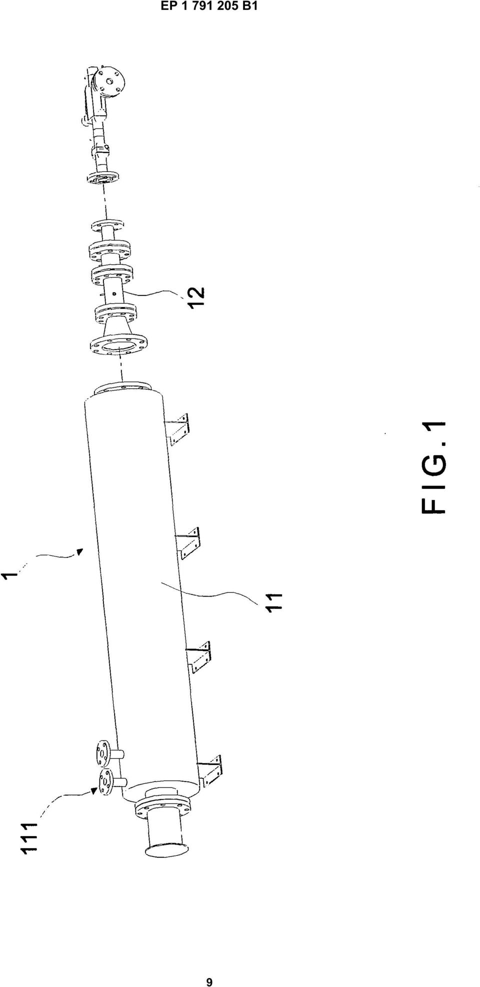
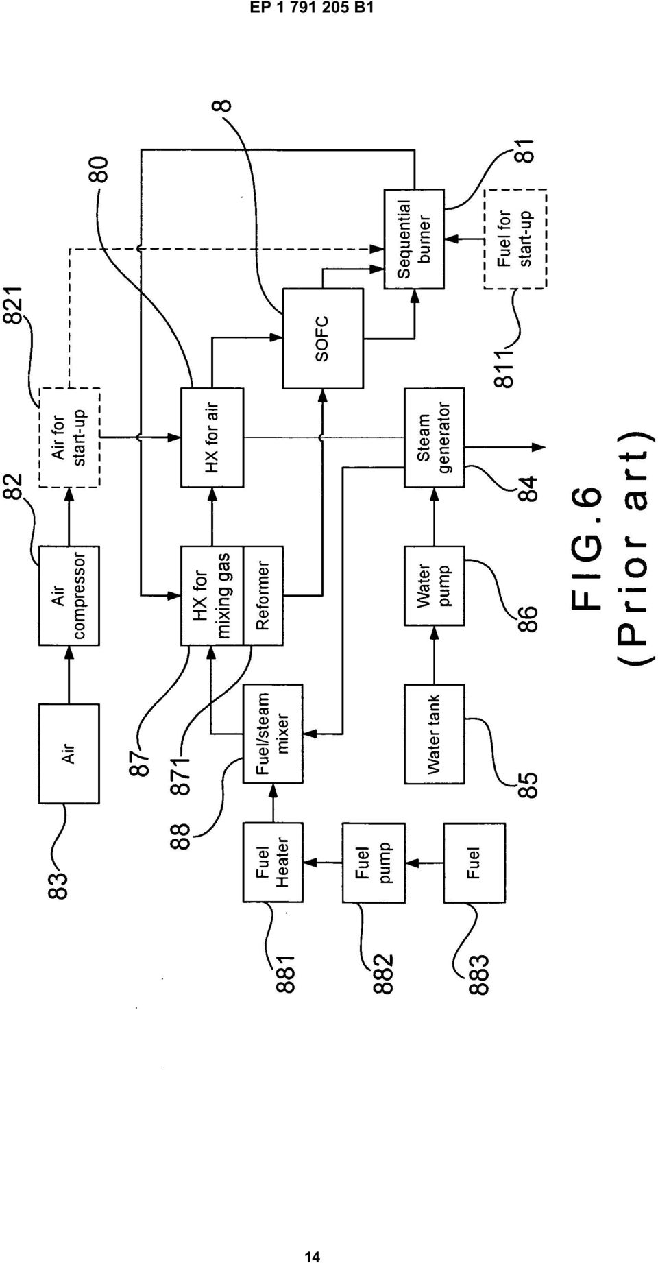
2 1 EP B1 2 Description Field of the invention [0001] The present invention relates to a thermal simulation apparatus; more particularly, it relates to running initial system integration tests of a solid oxide fuel cell (SOFC) with reduced costs by replacing the SOFC with the apparatus. Description of the Related Art [0002] As the price of energy is increasing, energy expense has become a big issue in the world nowadays. Methods for improving energy utilization efficiency are surely the most instant solutions. As is well-known, a fuel cell generates electric power through electrochemical reaction of hydrogen and oxygen, whose power-generating efficiency possesses high potential to all kinds of powergenerating technology, from a small electric power used in 3C products to a mega-watt-scaled electric power produced by a power plant. Among all kinds of fuel cells, SOFC shows the best efficiency. Yet, since it is run under a high temperature and the exhaust gas it produces is of high temperature too, it requires the most challenging technology among the fuel cells as well. And, as it is run under a temperature between 600 to 00 C, the performance parameters of the coordinated peripheral components, such as a reformer, a sequential burner and heat exchangers, have to be carefully considered for a successful thermal system integration of fuel cell. In another word, it is truly a prerequisite to the peripheral components that they must be able to sustain high-temperature operations. Hence, an integration examination of a SOFC not only requires a complete matching analysis; but also a down-to-earth experiment is essential. [0003] A disposition of a complete SOFC system of a prior art, as shown in FIG.6, comprises a SOFC 8; a heat exchanger for air flow 80 connecting to the SOFC 8; a sequential burner 81 connecting to the SOFC while having a fuel flow for start-up 811; an air compressor 82 compressing air 83 to supply an air for start-up 821 to the heat exchanger for air flow 80 and the sequential burner 81; a steam generator 84 connecting to the heat exchanger for air flow 80; a water tank 8 supplying water to the steam generator 84 by using a water pump 86; a heat exchanger for mixing gas 87 connecting respectively to the SOFC 8, the heat exchanger for air flow 80 and the sequential burner 81, coordinated with a reformer 871; a fuel/steam mixer 88 connecting to the steam generator 84 and the heat exchanger for mixing gas 87 and connecting to a fuel heater 881 supplying a fuel 883 by using a fuel pump 882. [0004] Nevertheless, a SOFC costs high and its structure is not strong, even weak with its main body, it does not sustain a severe operation or environment. Obviously, owing to its high cost, when the environment has a somewhat big change, a high loss might happen, which is not suitable in initial system integration tests. Hence, the prior art does not fulfill users requests on actual use. [000] A thermal simulator for thermal simulation of fuel cell comprising the features of the preamble portion of claim 1 is known from US 200/ A1. Summary of the invention [0006] The main purpose of the present invention is to test a sequential burner, a heat exchanger and/or other component by using a pre-heater and a simulation burner coordinated with a steam boiler, an air compressor, a gas supplier, a mixer and a reformer, where a SOFC is replaced to save costs when running initial system integration tests of the SOFC. [0007] To achieve the above purpose, the present invention is an apparatus for a thermal simulation of fuel cell, comprising a pre-heater heating an air flow passing by; and a simulation burner respectively located at an end of the pre-heater burning a fuel to raise the temperature of the air flow and to obtain another air flow having required components, coordinated with a steam boiler, an air compressor, a gas supplier, a mixer and a reformer, where a sequential burner, a heat exchanger or other component is tested. Accordingly, a novel apparatus for a thermal simulation of fuel cell is obtained. Brief descriptions of the drawings [0008] The present invention will be better understood from the following detailed descriptions of the preferred embodiments according to the present invention, taken in conjunction with the accompanying drawings, in which FIG.1 FIG.2 FIG.3 FIG.4 FIG. FIG.6 is an explosive view showing a fundamental structure of a first preferred embodiment according to the present invention; is a block view showing a flow chart according to a second preferred embodiment of the present invention; is a block view showing a flow chart according to a third preferred embodiment of the present invention: and is a block view showing a flow chart according to a fourth preferred embodiment of the present invention; is a block view showing a flow chart according to a fifth preferred embodiment of the present invention; is a disposition block view of a prior art. 2
![Description of the Related Art [0002] As the price of energy is increasing, energy expense has become a big issue in the world nowadays.](/docs-images/45/11595835/images/page_2.jpg "Methods for improving energy utilization efficiency are surely the most instant solutions.")
3 3 EP B1 4 Description of preferred embodiments [0009] The following description of the preferred embodiments are provided to understand the features and the structures of the present invention. [00] Please refer to FIG.1, which is an explosive view showing a fundamental structure of a first preferred embodiment according to the present invention. As shown in the figure, the present invention is an apparatus for a thermal simulation of fuel cell, where a thermal simulator 1 comprises a pre-heater 11 and a simulation burner 12; and the thermal simulator 1 plays a role as a solid oxide fuel cell (SOFC) where a component is tested with saved costs in initial system integration tests of the SOFC. [0011] The pre-heater 11 heats an air flow passing by until a predestined temperature between 400 and 600 C (Celsius degree) to supply heat so that a required temperature is obtained at an end of the simulation burner 12; the pre-heater 11 heats the air flow with an electric heater; and a plurality of inlet pipes 111 are deposed on the pre-heater 11. [0012] The simulation burner 12 is located at an end of the pre-heater 11 to produce an air flow simulating which is outputted from a sequential burner, a heat exchanger or other component; and the simulation burner 12 raises temperature of the air flow by burning a fuel. [0013] Please refer to FIG.2, which is a block view showing a flow chart according to a second preferred embodiment of the present invention. As shown in the figure, when using the present invention, a test object 6 of a heat exchanger is tested by using a thermal simulator 1 comprising a pre-heater 11 and a simulation burner, coordinated with a steam boiler 2, an air compressor 3, a gas supplier 4 and a mixer. [0014] The pre-heater 11 heats an air flow passing by until a predestined temperature between 400 and 600 C to supply heat so that a required temperature is obtained at an end of the simulation burner 12. [00] The simulation burner 12 is located at an end of the pre-heater 11 to produce an air flow simulating which is outputted from a heat exchanger; and the simulation burner 12 raises temperature of the air flow by burning a fuel. [0016] The steam boiler 2 is connected with the preheater 11 to provide a required steam flow for the thermal simulator 1 so that a steam amount at an output of a heat exchanger is simulated; and a mass flow controller (MFC) 21 is located between the steam boiler 2 and the preheater 11. [0017] The air compressor 3 is connected with the preheater 11 to provide required compressed air; and an MFC 31 is located between the air compressor 3 and the pre-heater 11. [0018] The gas supplier 4 is connected with the simulation burner 12; the gas supplier 4 is a steel cylinder to provide a methane (CH 4 ) or a natural gas; and an MFC 41 is located between the gas supplier 4 and the simulation burner 12. [0019] The mixer is connected to the gas supplier 4, the air compressor 3 and the simulation burner to mix airs; and an MFC 32 is located between the air compressor 3 and the mixer. [0020] The test object 6 is connected with the simulation burner 12. [0021] In the second preferred embodiment here, the test object 6 is a heat exchanger located downstream to the simulation burner 12 to recycle the thermal energy at an output of the simulation burner 12. Hence, the performance of the test object 6 is tested with the simulation burner 12 by simulating the gas outputted from a sequential burner. Because the output gas from a sequential burner is the same as that from burning a methane in air (only where the air is excessively supplied) yet the temperature obtained is higher than that obtained from purely burning the methane in air (which is a characteristic of SOFC), heat is supplied by using the pre-heater 11 to obtain required temperature when a sequential burner is simulated with the simulation burner 12. [0022] Please refer to FIG.3, which is a block view showing a flow chart according to a third preferred embodiment of the present invention. As shown in the figure, when using the present invention, a test object 6 other than a sequential burner, such as a heat exchanger, is tested by using a thermal simulator 1 comprising a preheater 11 and a simulation burner, coordinated with a reformer 7, a steam boiler 2, an air compressor 3 and a gas supplier 4. [0023] The pre-heater 11 heats an air flow passing by until a predestined temperature between 400 and 600 C to supply heat so that a required temperature is obtained at an end of the simulation burner 12. [0024] The simulation burner 12 is located at an end of the pre-heater 11 to produce an air flow simulating which is outputted from a component other than a sequential burner, such as a heat exchanger; and the simulation burner 12 raises temperature of the air flow by burning a fuel. [002] The reformer 7 is connected with the first simulation burner 12 to reform a hydrocarbon fuel to be rich in hydrogen. [0026] The steam boiler 2 is connected with the reformer 7 to provide a required steam flow for the reformer 7; and an MFC 22 is located between the steam boiler 2 and the reformer 7. [0027] The gas supplier 4 is connected with the reformer 7; the gas supplier 4 is a steel cylinder to provide a methane or a natural gas; and an MFC 48 is located between the gas supplier 4 and the reformer 7. [0028] The air compressor 3 is connected with the preheater 11 to provide required compressed air; and an MFC 33 is located between the air compressor 3 and the pre-heater 11. [0029] The test object 6 is connected with the simulation burner 12. [0030] The third preferred embodiment can be regard- 3
 where a component is tested with saved costs in initial system integration tests of the SOFC.")
4 EP B1 6 ed as an extension of the second preferred embodiment, where a fuel flow and a steam flow are supplied by a reformer 7. Thus, a component other than a sequential burner can be tested. [0031] Please refer to FIG.4, which is a block view showing a flow chart according to a fourth preferred embodiment of the present invention. As shown in the figure, a first test object 6a of a sequential burner is tested by using a first thermal simulator 1a, comprising a first preheater 11a and a first simulation burner 12a, and a second thermal simulator 1b, comprising a second pre-heater 11b and a second simulation burner 12b, coordinated with an air compressor 3, a first gas supplier 4a, a second gas supplier 4b and a third gas supplier 4c. [0032] The first pre-heater 11a and the second preheater 11b heat a first and a second air flows passing by to a predestined temperature between 400 and 600 C to supply heat so that a required temperature is obtained at each end of the first simulation burner 12a and the second simulation burner 12b respectively. [0033] The first simulation burner 12a is located at an end of the first pre-heater 11a to produce a first air flow simulating which is outputted from a cathode of a SOFC; and the first simulation burner 12a raises temperature of the first air flow by burning a fuel. [0034] The second simulation burner 12b is located at an end of the second pre-heater 11b to produce a second air flow simulating which is outputted from an anode of the SOFC; and the second simulation burner 12b raises temperature of the second air flow by burning a fuel. [003] The air compressor 3 is connected with the first pre-heater 11a to provide required compressed air; and an MFC 31a is located between the air compressor 3 and the first pre-heater 11a. [0036] The first gas supplier 4a is connected with the first simulation burner 12a; the first gas supplier 4a is a steel cylinder to provide a methane or hydrogen (H 2 ); and an MFC 41a is located between the first gas supplier 4a and the first simulation burner 12a. [0037] The second gas supplier 4a is connected with the second simulation burner 12a; the second gas supplier 4a comprises steel cylinders 42b,43b to provide hydrogen (H 2 ) and oxygen (O 2 ); and an MFC 421b,431b is located between each steel cylinder 42b,43b and the second simulation burner 12b. [0038] The third gas supplier 4c is connected with the second pre-heater 11b; the third gas supplier 4c comprises steel cylinders 44c,4c,46c,47c to provide a methane, hydrogen, carbon monoxide (CO) and carbon dioxide (CO 2 ); and an MFC 441c,41c,461c,471c is located between each steel cylinder 44c,4c,46c,47c and the second pre-heater 11b. [0039] The first test object 6a is connected with the first simulation burner 12a and the second pre-heater 11b. [0040] The output at a cathode of the SOFC is an air with high temperature, which comprises less oxygen than regular air after passing through an anode and a solid electrolyte. Therefore, when the first thermal simulator 1a is used to simulate the cathode of the SOFC, some oxygen in the air is consumed by a burning with some adequate fuel added to the first simulation burner 12a so that a required oxygen amount in the output of the cathode of the SOFC is simulated. Although the burning produces CO 2 and H 2 O, their amounts are so tiny that they almost do nothing to the sequential burner. Besides, the temperature of the air is also raised by the burning so that the power required by the first pre-heater 11a is reduced. Regarding the output air at the anode of the SOFC, the output air may comprises H 2, CH 4, CO, CO 2 and H 2 O, where H 2 O takes the most part, and H 2 and CO 2 follows. Thus, a second thermal simulator 1b is used to simulate the cathode of the SOFC by a burning of H 2 and O 2 in the second thermal simulator 1b so that a required amount of H 2 O is obtained and the power required by the second pre-heater 1b is reduced. The other components of the fuel are sent to the second pre-heater 11b through the MFCs 441c,41c,461c,471c of the third gas supplier 4c to be mixed with the output air flow from the second simulation burner. Thus, the output air at the anode of the SOFC is obtained. [0041] Please further refer to FIG., which is a block view showing a flow chart according to a fifth preferred embodiment of the present invention. As shown in the figure, two connected test objects are located downstream to the first simulation burner 12a, which comprises a first test object 6a of a sequential burner and a second test object 6b of a heat exchanger. By doing so, the first test object 6a and the second test object 6b are tested simultaneously. [0042] To sum up, the present invention is an apparatus for a thermal simulation of fuel cell, where a sequential burner, a heat exchanger or other component is tested by using a pre-heater and a simulation burner coordinated with a steam boiler, an air compressor, a gas supplier, a mixer and a reformer. Consequently, a SOFC can be replaced with the apparatus when running initial system integration tests of the SOFC. [0043] The preferred embodiments herein disclosed are not intended to unnecessarily limit the scope of the invention. Therefore, simple modifications or variations belonging to the equivalent of the scope of the claims and the instructions disclosed herein for a patent are all within the scope of the present invention. Claims 1. Thermal simulator (1) for the thermal simulation of a fuel cell, wherein the fuel cell is replaced by said thermal simulator, said thermal simulator (1) comprising: at least a pre-heater (11) heating a flow passing by, the flow being selected from an air flow and a steam flow; 4

5 7 EP B1 8 characterized by at least a simulation burner (12) located at an end of the pre-heater (11) to raise temperature of the air flow by burning a fuel and to obtain another air flow having predestined elements. 2. Thermal simulator according to claim 1, wherein the pre-heater (11) heats the air flow with an electric heater. 3. Thermal simulator according to claim 1 or 2, wherein a plurality of inlet pipes (111) are deposed on the pre-heater (11). 4. Apparatus, comprising a thermal simulator (1) according to claim 1 wherein the at least one pre-heater comprises a pre-heater (11) heating an air flow passing by, characterized by a steam boiler (2) connecting to the pre-heater (11) to provide steam; an air compressor (3) connecting to the pre-heater (11) and the simulation burner (12) to provide compressed air; a gas supplier (4) connecting to the simulation burner (12); a mixer () connecting to the gas supplier, the air compressor and the simulation burner, the mixer mixing airs from the gas supplier and the air compressor and delivering the mixture to the simulation burner; and a test object (6) connecting to the simulation burner (12).. Apparatus according to claim 4, wherein the gas supplier (4) comprises a steel cylinder providing a gas selected from a group consisting of a methane (CH 4 ) and a natural gas. 6. Apparatus according to claim 4 or, wherein the test object (6) is a heat exchanger. 7. Apparatus according to one of claim 4 to 6, wherein a mass flow controller (MFC) is located between the steam boiler (2) and the pre-heater (11); wherein an MFC is located between the air compressor and the pre-heater; wherein an MFC is located between the air compressor and the mixer; and wherein an MFC is located between the gas supplier and the mixer to provide a steam flow for the reformer; and wherein the gas supplier (4) connects to the reformer, the gas supplier comprising a steel cylinder providing methane. 9. Apparatus according to claim 8, wherein an MFC is located between the steam boiler (2) and the reformer (7); and wherein an MFC is located between the gas supplier (4) and the reformer (7).. Apparatus comprising two thermal simulators (1) of claim 1, wherein a first thermal simulator (1a) comprises a first preheater (11a) heating a first air flow passing by and a first simulation burner (12a) located at an end of the first pre-heater to raise temperature of the first air flow and to obtain an air flow having predestined components, and a second thermal simulator (1b) comprises a second pre-heater (11b) heating a second air flow passing by anda second simulation burner (12b) located at an end of the second pre-heater to raise temperature of the second air flow and to obtain an air flow having predestined components, characterized by an air compressor (421b) connecting to the first preheater to provide a compressed air; a first gas supplier (4a) connecting to the first simulation burner; a second gas supplier (4b) connecting to the second simulation burner; a third gas supplier connecting to the second preheater: and a test object (6a, 6b) connecting to the first simulation burner and the second pre-heater. 11. Apparatus according to claim, wherein the first gas supplier (4a) comprises a steel cylinder providing a gas selected from a group consisting of a methane and hydrogen. 12. Apparatus according to claim or 11, wherein the second gas supplier (4b) comprises steel cylinders providing hydrogen (H 2 ) and oxygen (O 2 ). 13. Apparatus according to one of claims to 12, wherein the third gas supplier comprises steel cylinders providing a methane, hydrogen, carbon monoxide (CO) and carbon dioxide (CO 2 ). 8. Apparatus according to one of claims 4 to 7, wherein the mixer is a reformer (7), the reformer connecting to the gas supplier (4) and the steam boiler (2) at an end, the reformer connecting to the simulation burner (12) at another end, the reformer reforming air into an air containing hydrogen; wherein the steam boiler (2) connects to the reformer 14. Apparatus according to one of claims to 13, wherein the test object (6a, 6b) is a sequential burner.. Apparatus according to one of claims to 13, wherein the test object (6a, 6b) is a sequential burner connected with a heat exchanger.
 according to claim 1 wherein the at least one pre-heater comprises a pre-heater (11) heating an air flow passing by, characterized by a steam boiler (2)")
6 9 EP B1 16. Apparatus according to one of claims to, wherein an MFC is located between the air compressor and the first pre-heater; wherein an MFC is located between the first gas supplier and the first simulation burner; wherein an MFC is located between each steel cylinder of the second gas supplier and the second simulation burner; and wherein an MFC is located between each steel cylinder of the third gas supplier and the second simulation burner. Patentansprüche 1. Thermischer Simulator (1) zur thermischen Simulation einer Brennstoffzelle, wobei die Brennstoffzelle durch den thermischen Simulator ersetzt wird und der thermische Simulator (1) umfasst: mindestens einen Vorwärmer (11), der einen vorbeiströmenden Strom erwärmt, wobei der Strom aus einem Luftstrom und einem Dampfstrom ausgewählt ist; gekennzeichnet durch mindestens einen Simulationsbrenner (12), der an einem Ende des Vorwärmers (11) angeordnet ist, um die Temperatur des Luftstroms durch Verbrennen eines Brennstoffs anzuheben und einen weiteren Luftstrom zu erhalten, der vorgegebene Elemente aufweist. 2. Thermischer Simulator nach Anspruch 1, wobei der Vorwärmer (11) den Luftstrom mithilfe eines elektrischen Heizers erwärmt. 3. Thermischer Simulator nach Anspruch 1 oder 2, wobei eine Vielzahl von Ansaugrohren (111) an dem Vorwärmer (11) angeordnet ist. 4. Vorrichtung, die einen thermischen Simulator (1) nach Anspruch 1 umfasst, wobei der mindestens eine Vorwärmer einen Vorwärmer (11) umfasst, der einen vorbeiströmenden Luftstrom erwärmt, gekennzeichnet durch einen Dampfkessel (2), der an den Vorwärmer (11) angeschlossen ist, um Dampf bereitzustellen; einen Luftkompressor (3), der an den Vorwärmer (11) und den Simulationsbrenner (12) angeschlossen ist, um Druckluft bereitzustellen; eine Gaszufuhr (4), die an den Simulationsbrenner (12) angeschlossen ist; einen Mischer (), der an die Gaszufuhr, den Luftkompressor und den Simulationsbrenner angeschlossen ist, wobei der Mischer die Luft aus der Gaszufuhr und dem Luftkompressor mischt und das Gemisch an den Simulationsbrenner liefert; und ein Testobjekt (6), das an den Simulationsbrenner (12) angeschlossen ist.. Vorrichtung nach Anspruch 4, wobei die Gaszufuhr (4) einen Stahlzylinder umfasst, der ein Gas bereitstellt, das aus der Gruppe bestehend aus Methangas (CH 4 ) und Erdgas ausgewählt ist. 6. Vorrichtung nach Anspruch 4 oder, wobei das Testobjekt (6) ein Wärmetauscher ist. 7. Vorrichtung nach einem der Ansprüche 4 bis 6, wobei ein Mengenregler (MFC) zwischen dem Dampfkessel (2) und dem Vorwärmer (11) angeordnet ist; wobei ein Mengenregler (MFC) zwischen dem Luftkompressor und dem Vorwärmer angeordnet ist; wobei ein Mengenregler (MFC) zwischen dem Luftkompressor und dem Mischer angeordnet ist; und wobei ein Mengenregler (MFC) zwischen der Gaszufuhr und dem Mischer angeordnet ist. 8. Vorrichtung nach einem der Ansprüche 4 bis 7, wobei der Mischer ein Reformer (7) ist, der Reformer an einem Ende an die Gaszufuhr (4) und den Dampfkessel (2) angeschlossen ist, der Reformer am anderen Ende an den Simulationsbrenner (12) angeschlossen ist, und der Reformer Luft in einen luftenthaltenden Wasserstoff reformiert; wobei der Dampfkessel (2) an den Reformer angeschlossen ist, um einen Dampfstrom für den Reformer bereitzustellen; und wobei die Gaszufuhr (4) an den Reformer angeschlossen ist und die Gaszufuhr einen Stahlzylinder umfasst, der Methan bereitstellt. 9. Vorrichtung nach Anspruch 8, wobei ein Mengenregler (MFC) zwischen dem Dampfkessel (2) und dem Reformer (7) angeordnet ist; und wobei ein Mengenregler (MFC) zwischen der Gaszufuhr (4) und dem Reformer (7) angeordnet ist.. Vorrichtung, umfassend zwei thermische Simulatoren (1) nach Anspruch 1, wobei ein erster thermischer Simulator (1a) einen ersten Vorwärmer (11a) umfasst, der einen ersten vorbeiströmenden Luftstrom erwärmt, und einen ersten Simulationsbrenner (12a), der an einem Ende des ersten Vorwärmers angeordnet ist, damit die Temperatur des ersten Luftstroms angehoben und ein Luftstrom erhalten wird, der vorgegebene Komponenten aufweist, und ein zweiter thermischer Simulator (1b) einen zweiten Vorwärmer (11b) umfasst, der einen zweiten vorbeiströmenden Luftstrom erwärmt, und einen zweiten Simulationsbrenner (12b), der an einem Ende des zweiten Vorwärmers angeordnet ist, damit die Temperatur des zweiten Luftstroms angehoben und ein 6

7 11 EP B1 12 Luftstrom erhalten wird, der vorgegebene Komponenten aufweist, gekennzeichnet durch einen Luftkompressor (421b), der an den ersten Vorwärmer angeschlossen ist, um Druckluft bereitzustellen; eine erste Gaszufuhr (4a), die an den ersten Simulationsbrenner angeschlossen ist; eine zweite Gaszufuhr (4b), die an den zweiten Simulationsbrenner angeschlossen ist; eine dritte Gaszufuhr, die an den zweiten Vorwärmer angeschlossen ist; und ein Testobjekt (6a, 6b), das an den ersten Simulationsbrenner und den zweiten Vorwärmer angeschlossen ist. 11. Vorrichtung nach Anspruch, wobei die erste Gaszufuhr (4a) einen Stahlzylinder umfasst, der ein Gas bereitstellt, das aus der Gruppe bestehend aus Methangas und Wasserstoff gewählt ist. 20 étant remplacée par ledit simulateur thermique, ledit simulateur thermique (1) comprenant : au moins un préchauffeur (11) qui chauffe un flux qui passe, le flux étant sélectionné parmi un flux d air et un flux de vapeur, caractérisé par au moins un brûleur de simulation (12) situé à une extrémité du préchauffeur (11) pour augmenter la température du flux d air en brûlant un combustible et pour obtenir un autre flux d air ayant des éléments prédestinés. 2. Simulateur thermique selon la revendication 1 dans lequel le préchauffeur (11) chauffe le flux d air avec un dispositif de chauffage électrique. 3. Simulateur thermique selon la revendication 1 ou 2 dans lequel une pluralité de tuyaux d admission (111) est déposée sur le préchauffeur (11). 12. Vorrichtung nach Anspruch oder 11, wobei die zweite Gaszufuhr (4b) Stahlzylinder umfasst, die Wasserstoff (H 2 ) und Sauerstoff (O 2 ) bereitstellen. 13. Vorrichtung nach einem der Ansprüche bis 12, wobei die dritte Gaszufuhr Stahlzylinder umfasst, die Methan, Wasserstoff, Kohlenmonoxid (CO) und Kohlendioxid (CO 2 ) bereitstellen. 14. Vorrichtung nach einem der Ansprüche bis 13, wobei das Testobjekt (6a, 6b) ein sequentieller Brenner ist.. Vorrichtung nach einem der Ansprüche bis 13, wobei das Testobjekt (6a, 6b) ein sequentieller Brenner ist, der an einen Wärmetauscher angeschlossen ist. 16. Vorrichtung nach einem der Ansprüche bis, wobei ein Mengenregler (MFC) zwischen dem Luftkompressor und dem ersten Vorwärmer angeordnet ist; wobei ein Mengenregler (MFC) zwischen der ersten Gaszufuhr und dem ersten Simulationsbrenner angeordnet ist. wobei ein Mengenregler (MFC) zwischen jedem Stahlzylinder der zweiten Gaszufuhr und dem zweiten Simulationsbrenner angeordnet ist; und wobei ein Mengenregler (MFC) zwischen jedem Stahlzylinder der dritten Gaszufuhr und dem zweiten Simulationsbrenner angeordnet ist. Revendications 1. Simulateur thermique (1) pour la simulation thermique d une pile à combustible, la pile à combustible Appareil comprenant un simulateur thermique (1) selon la revendication 1 dans lequel le préchauffeur qui existe au moins comprend un préchauffeur (11) qui chauffe un flux d air qui passe, caractérisé par : une chaudière à vapeur (2) reliée au préchauffeur (11) pour procurer de la vapeur ; un compresseur d air (3) relié au préchauffeur (11) et au brûleur de simulation (12) pour procurer de l air comprimé ; un fournisseur de gaz (4) relié au brûleur de simulation (12) ; un mélangeur () relié au fournisseur de gaz, au compresseur d air et au brûleur de simulation, le mélangeur mélangeant l air du fournisseur de gaz et du compresseur d air et qui livre le mélange au brûleur de simulation et un objet à tester (6) relié au brûleur de simulation (12).. Appareil selon la revendication 4 dans lequel le fournisseur de gaz (4) comprend un cylindre d acier procurant un gaz sélectionné dans un groupe comprenant un méthane (CH 4 ) et un gaz naturel. 6. Appareil selon la revendication 4 ou dans lequel l objet à tester (6) est un échangeur thermique. 7. Appareil selon l une des revendications 4 à 6 dans lequel un contrôleur de débit massique (MFC) est situé entre la chaudière à vapeur (2) et le préchauffeur (11), dans lequel un contrôleur de débit massique (MFC) est situé entre le compresseur d air et le préchauffeur, dans lequel un contrôleur de débit massique (MFC) est situé entre le compresseur d air et le mélangeur et dans lequel un contrôleur de débit massique (MFC) est situé entre le fournisseur de 7
 einen Stahlzylinder umfasst, der ein Gas bereitstellt, das aus der Gruppe bestehend aus Methangas und Wasserstoff gewählt ist.")
8 13 EP B1 14 gaz et le mélangeur. 8. Appareil selon l une des revendications 4 à 7 dans lequel le mélangeur est un reformeur (7), le reformeur étant relié au fournisseur de gaz (4) et à la chaudière à vapeur (2) à une extrémité, le reformeur étant relié au brûleur de simulation (12) à une autre extrémité, le reformeur reformant de l air en air contenant de l hydrogène, dans lequel la chaudière à vapeur (2) est reliée au reformeur pour fournir un flux de vapeur au reformeur et dans lequel le fournisseur de gaz (4) est relié au reformeur, le fournisseur de gaz comprenant un cylindre d acier procurant du méthane. 9. Appareil selon la revendication 8 dans lequel un contrôleur de débit massique (MFC) est situé entre la chaudière à vapeur (2) et le reformeur (7) et dans lequel un contrôleur de débit massique (MFC) est situé entre le fournisseur de gaz (4) et le reformeur (7).. Appareil comprenant deux simulateurs thermiques (1) selon la revendication 1 dans lequel un premier simulateur thermique (1a) comprend un premier préchauffeur (11a) chauffant un premier flux d air qui passe et un premier brûleur de simulation (12a) situé à une extrémité du premier préchauffeur pour augmenter la température du premier flux d air et pour obtenir un flux d air qui a des composants prédestinés et un second simulateur thermique (1b) comprend un second préchauffeur (11b) qui chauffe un second flux d air qui passe et un second brûleur de simulation (12b) situé à une extrémité du second préchauffeur pour augmenter la température du second flux d air et pour obtenir un flux d air qui a des composants prédestinés, caractérisé par un compresseur d air (421b) relié au premier préchauffeur pour procurer de l air compressé, un premier fournisseur de gaz (4a) relié au premier brûleur de simulation, un second fournisseur de gaz (4b) relié au second brûleur de simulation, un troisième fournisseur de gaz relié au second préchauffeur et un objet à tester (6a, 6b) relié au premier brûleur de simulation et au second préchauffeur Appareil selon l une des revendications à 12 dans lequel le troisième fournisseur de gaz comprend des cylindres d acier qui procurent un méthane, de l hydrogène, du monoxyde de carbone (CO) et du dioxyde de carbone (CO 2 ). 14. Appareil selon l une des revendications à 13 dans lequel l objet à tester (6a, 6b) est un brûleur séquentiel.. Appareil selon l une des revendications à 13 dans lequel l objet à tester (6a, 6b) est un brûleur séquentiel lié à un échangeur thermique. 16. Appareil selon l une des revendications à dans lequel un contrôleur de débit massique (MFC) est situé entre le compresseur d air et le premier préchauffeur, dans lequel un contrôleur de débit massique (MFC) est situé entre le premier fournisseur de gaz et le premier brûleur de simulation, dans lequel un contrôleur de débit massique (MFC) est situé entre chaque cylindre d acier du second fournisseur de gaz et le second brûleur de simulation et un contrôleur de débit massique (MFC) est situé entre chaque cylindre d acier du troisième fournisseur de gaz et le second brûleur de simulation. 11. Appareil selon la revendication dans lequel le premier fournisseur de gaz (4a) comprend un cylindre d acier qui procure un gaz sélectionné dans un groupe comprenant un méthane et de l hydrogène Appareil selon la revendication ou 11 dans lequel le second fournisseur de gaz (4b) comprend des cylindres d acier procurant de l hydrogène (H 2 ) et de l oxygène (O 2 ). 8
 est relié au reformeur, le fournisseur de gaz comprenant un cylindre d acier procurant du méthane. 9.")
9 EP B1 9
10 EP B1

11 EP B1 11

12 EP B1 12

13 EP B1 13

14 EP B1 14
15 EP B1 REFERENCES CITED IN THE DESCRIPTION This list of references cited by the applicant is for the reader s convenience only. It does not form part of the European patent document. Even though great care has been taken in compiling the references, errors or omissions cannot be excluded and the EPO disclaims all liability in this regard. Patent documents cited in the description US A1 [000]

*EP001173363B1* EP 1 173 363 B1 (19) (11) EP 1 173 363 B1 (12) EUROPEAN PATENT SPECIFICATION
 (11) EP 1 173 363 B1 (12) EUROPEAN PATENT SPECIFICATION") (19) Europäisches Patentamt European Patent Office Office européen des brevets *EP001173363B1* (11) EP 1 173 363 B1 (12) EUROPEAN PATENT SPECIFICATION (4) Date of publication and mention of the grant of
(19) Europäisches Patentamt European Patent Office Office européen des brevets *EP001173363B1* (11) EP 1 173 363 B1 (12) EUROPEAN PATENT SPECIFICATION (4) Date of publication and mention of the grant of
(51) Int Cl.: H04L 29/06 (2006.01) G06F 9/445 (2006.01) G06F 13/00 (2006.01)
 Int Cl.: H04L 29/06 (2006.01) G06F 9/445 (2006.01) G06F 13/00 (2006.01)") (19) TEPZZ_7486_6B_T (11) EP 1 748 616 B1 (12) EUROPEAN PATENT SPECIFICATION (4) Date of publication and mention of the grant of the patent: 03.09.2014 Bulletin 2014/36 (1) Int Cl.: H04L 29/06 (2006.01)
(19) TEPZZ_7486_6B_T (11) EP 1 748 616 B1 (12) EUROPEAN PATENT SPECIFICATION (4) Date of publication and mention of the grant of the patent: 03.09.2014 Bulletin 2014/36 (1) Int Cl.: H04L 29/06 (2006.01)
TEPZZ_768 7_B_T EP 1 768 371 B1 (19) (11) EP 1 768 371 B1 (12) EUROPEAN PATENT SPECIFICATION. (51) Int Cl.: H04M 19/04 (2006.01)
 (11) EP 1 768 371 B1 (12) EUROPEAN PATENT SPECIFICATION. (51) Int Cl.: H04M 19/04 (2006.01)") (19) TEPZZ_768 7_B_T (11) EP 1 768 371 B1 (12) EUROPEAN PATENT SPECIFICATION (4) Date of publication and mention of the grant of the patent: 1.01.2014 Bulletin 2014/03 (1) Int Cl.: H04M 19/04 (2006.01)
(19) TEPZZ_768 7_B_T (11) EP 1 768 371 B1 (12) EUROPEAN PATENT SPECIFICATION (4) Date of publication and mention of the grant of the patent: 1.01.2014 Bulletin 2014/03 (1) Int Cl.: H04M 19/04 (2006.01)
(51) Int Cl.: G05F 3/26 (2006.01) G05F 3/24 (2006.01)
 Int Cl.: G05F 3/26 (2006.01) G05F 3/24 (2006.01)") (19) Europäisches Patentamt European Patent Office Office européen des brevets (11) EP 1 280 033 B1 (12) EUROPEAN PATENT SPECIFICATION (4) Date of publication and mention of the grant of the patent: 31.0.2006
(19) Europäisches Patentamt European Patent Office Office européen des brevets (11) EP 1 280 033 B1 (12) EUROPEAN PATENT SPECIFICATION (4) Date of publication and mention of the grant of the patent: 31.0.2006
(51) Int Cl.: G06F 13/38 (2006.01) G06F 1/16 (2006.01)
 Int Cl.: G06F 13/38 (2006.01) G06F 1/16 (2006.01)") (19) TEPZZ 9777B_T (11) EP 2 97 77 B1 (12) EUROPEAN PATENT SPECIFICATION (4) Date of publication and mention of the grant of the patent: 1.07.1 Bulletin 1/29 (1) Int Cl.: G06F 13/38 (06.01) G06F 1/16 (06.01)
(19) TEPZZ 9777B_T (11) EP 2 97 77 B1 (12) EUROPEAN PATENT SPECIFICATION (4) Date of publication and mention of the grant of the patent: 1.07.1 Bulletin 1/29 (1) Int Cl.: G06F 13/38 (06.01) G06F 1/16 (06.01)
(51) Int Cl.: C08K 5/523 (2006.01) C08K 5/521 (2006.01) C08K 5/52 (2006.01) C08G 64/00 (2006.01)
 Int Cl.: C08K 5/523 (2006.01) C08K 5/521 (2006.01) C08K 5/52 (2006.01) C08G 64/00 (2006.01)") (19) Europäisches Patentamt European Patent Office Office européen des brevets (11) EP 0 78 966 B1 (12) EUROPEAN PATENT SPECIFICATION (4) Date of publication and mention of the grant of the patent: 01.03.06
(19) Europäisches Patentamt European Patent Office Office européen des brevets (11) EP 0 78 966 B1 (12) EUROPEAN PATENT SPECIFICATION (4) Date of publication and mention of the grant of the patent: 01.03.06
(51) Int Cl.: H04W 4/14 (2009.01)
 Int Cl.: H04W 4/14 (2009.01)") (19) (12) EUROPEAN PATENT SPECIFICATION (11) EP 2 184 897 B1 (4) Date of publication and mention of the grant of the patent: 14.03.12 Bulletin 12/11 (21) Application number: 087774.3 (22) Date of filing:
(19) (12) EUROPEAN PATENT SPECIFICATION (11) EP 2 184 897 B1 (4) Date of publication and mention of the grant of the patent: 14.03.12 Bulletin 12/11 (21) Application number: 087774.3 (22) Date of filing:
(51) Int Cl.: H05K 1/02 (2006.01)
 Int Cl.: H05K 1/02 (2006.01)") (19) (11) EP 1 229 767 B1 (12) EUROPEAN PATENT SPECIFICATION (4) Date of publication and mention of the grant of the patent: 20.01.2010 Bulletin 2010/03 (1) Int Cl.: H0K 1/02 (2006.01) (21) Application
(19) (11) EP 1 229 767 B1 (12) EUROPEAN PATENT SPECIFICATION (4) Date of publication and mention of the grant of the patent: 20.01.2010 Bulletin 2010/03 (1) Int Cl.: H0K 1/02 (2006.01) (21) Application
(51) Int Cl.: B29C 41/20 (2006.01) F21S 4/00 (2006.01) H05K 3/28 (2006.01)
 Int Cl.: B29C 41/20 (2006.01) F21S 4/00 (2006.01) H05K 3/28 (2006.01)") (19) TEPZZ 68698B_T (11) EP 2 68 698 B1 (12) EUROPEAN PATENT SPECIFICATION (4) Date of publication and mention of the grant of the patent: 18.11.201 Bulletin 201/47 (21) Application number: 11808612.3
(19) TEPZZ 68698B_T (11) EP 2 68 698 B1 (12) EUROPEAN PATENT SPECIFICATION (4) Date of publication and mention of the grant of the patent: 18.11.201 Bulletin 201/47 (21) Application number: 11808612.3
(51) Int Cl. 7 : G03G 15/00
 Int Cl. 7 : G03G 15/00") (19) Europäisches Patentamt European Patent Office Office européen des brevets *EP001179B1* (11) EP 1 17 9 B1 (12) EUROPEAN PATENT SPECIFICATION (4) Date of publication and mention of the grant of the
(19) Europäisches Patentamt European Patent Office Office européen des brevets *EP001179B1* (11) EP 1 17 9 B1 (12) EUROPEAN PATENT SPECIFICATION (4) Date of publication and mention of the grant of the
(51) Int Cl.: G06F 21/00 (2006.01) H04L 29/06 (2006.01)
 Int Cl.: G06F 21/00 (2006.01) H04L 29/06 (2006.01)") (19) TEPZZ_8Z_7 _B_T (11) EP 1 801 721 B1 (12) EUROPEAN PATENT SPECIFICATION (4) Date of publication and mention of the grant of the patent: 16.06. Bulletin /24 (1) Int Cl.: G06F 21/00 (06.01) H04L 29/06
(19) TEPZZ_8Z_7 _B_T (11) EP 1 801 721 B1 (12) EUROPEAN PATENT SPECIFICATION (4) Date of publication and mention of the grant of the patent: 16.06. Bulletin /24 (1) Int Cl.: G06F 21/00 (06.01) H04L 29/06
(51) Int Cl.: H04N 5/225 (2006.01)
 Int Cl.: H04N 5/225 (2006.01)") (19) TEPZZ_94 66_B_T (11) EP 1 942 661 B1 (12) EUROPEAN PATENT SPECIFICATION (4) Date of publication and mention of the grant of the patent: 17.09.2014 Bulletin 2014/38 (1) Int Cl.: H04N /22 (2006.01)
(19) TEPZZ_94 66_B_T (11) EP 1 942 661 B1 (12) EUROPEAN PATENT SPECIFICATION (4) Date of publication and mention of the grant of the patent: 17.09.2014 Bulletin 2014/38 (1) Int Cl.: H04N /22 (2006.01)
The Advantialer and Its Advantages
 (19) TEPZZ Z B_T (11) EP 2 0 113 B1 (12) EUROPEAN PATENT SPECIFICATION (4) Date of publication and mention of the grant of the patent: 16.09.1 Bulletin 1/38 (21) Application number: 07809477.8 (22) Date
(51) Int Cl.: H04L 12/24 (2006.01)
 Int Cl.: H04L 12/24 (2006.01)") (19) TEPZZ_8_9Z96B_T (11) EP 1 819 096 B1 (12) EUROPEAN PATENT SPECIFICATION (4) Date of publication and mention of the grant of the patent: 24..12 Bulletin 12/43 (21) Application number: 0818628.9 (22)
(19) TEPZZ_8_9Z96B_T (11) EP 1 819 096 B1 (12) EUROPEAN PATENT SPECIFICATION (4) Date of publication and mention of the grant of the patent: 24..12 Bulletin 12/43 (21) Application number: 0818628.9 (22)
(51) Int Cl.: H04N 7/16 (2011.01)
 Int Cl.: H04N 7/16 (2011.01)") (19) TEPZZ_796 89B_T (11) EP 1 796 389 B1 (12) EUROPEAN PATENT SPECIFICATION (4) Date of publication and mention of the grant of the patent: 04.03.1 Bulletin 1/ (1) Int Cl.: H04N 7/16 (11.01) (21) Application
(19) TEPZZ_796 89B_T (11) EP 1 796 389 B1 (12) EUROPEAN PATENT SPECIFICATION (4) Date of publication and mention of the grant of the patent: 04.03.1 Bulletin 1/ (1) Int Cl.: H04N 7/16 (11.01) (21) Application
TEPZZ 5Z _9_B_T EP 2 502 191 B1 (19) (11) EP 2 502 191 B1 (12) EUROPEAN PATENT SPECIFICATION
 (11) EP 2 502 191 B1 (12) EUROPEAN PATENT SPECIFICATION") (19) TEPZZ Z _9_B_T (11) EP 2 02 191 B1 (12) EUROPEAN PATENT SPECIFICATION (4) Date of publication and mention of the grant of the patent: 17.06.1 Bulletin 1/2 (21) Application number: 787872.0 (22) Date
(19) TEPZZ Z _9_B_T (11) EP 2 02 191 B1 (12) EUROPEAN PATENT SPECIFICATION (4) Date of publication and mention of the grant of the patent: 17.06.1 Bulletin 1/2 (21) Application number: 787872.0 (22) Date
(51) Int Cl.: H04L 12/26 (2006.01)
 Int Cl.: H04L 12/26 (2006.01)") (19) TEPZZ 84 8B_T (11) EP 2 84 338 B1 (12) EUROPEAN PATENT SPECIFICATION (4) Date of publication and mention of the grant of the patent: 23.09.1 Bulletin 1/39 (1) Int Cl.: H04L 12/26 (06.01) (21) Application
(19) TEPZZ 84 8B_T (11) EP 2 84 338 B1 (12) EUROPEAN PATENT SPECIFICATION (4) Date of publication and mention of the grant of the patent: 23.09.1 Bulletin 1/39 (1) Int Cl.: H04L 12/26 (06.01) (21) Application
(51) Int Cl.: H04M 3/50 (2006.01)
 Int Cl.: H04M 3/50 (2006.01)") (19) TEPZZ_Z48_64B_T (11) EP 1 048 164 B1 (12) EUROPEAN PATENT SPECIFICATION (4) Date of publication and mention of the grant of the patent: 07.01.1 Bulletin 1/02 (21) Application number: 9893133.0 (22)
(19) TEPZZ_Z48_64B_T (11) EP 1 048 164 B1 (12) EUROPEAN PATENT SPECIFICATION (4) Date of publication and mention of the grant of the patent: 07.01.1 Bulletin 1/02 (21) Application number: 9893133.0 (22)
(51) Int Cl.: H04L 9/24 (2006.01) G06Q 10/00 (2012.01)
 Int Cl.: H04L 9/24 (2006.01) G06Q 10/00 (2012.01)") (19) TEPZZ_4Z 68ZB_T (11) EP 1 2 680 B1 (12) EUROPEAN PATENT SPECIFICATION (4) Date of publication and mention of the grant of the patent: 01.04.1 Bulletin 1/14 (21) Application number: 02741722.9 (22)
(19) TEPZZ_4Z 68ZB_T (11) EP 1 2 680 B1 (12) EUROPEAN PATENT SPECIFICATION (4) Date of publication and mention of the grant of the patent: 01.04.1 Bulletin 1/14 (21) Application number: 02741722.9 (22)
(51) Int Cl.: G10L 15/26 (2006.01)
 Int Cl.: G10L 15/26 (2006.01)") (19) TEPZZ Z 8B_T (11) EP 2 023 338 B1 (12) EUROPEAN PATENT SPECIFICATION (4) Date of publication and mention of the grant of the patent: 28.0.14 Bulletin 14/22 (1) Int Cl.: GL /26 (06.01) (21) Application
(19) TEPZZ Z 8B_T (11) EP 2 023 338 B1 (12) EUROPEAN PATENT SPECIFICATION (4) Date of publication and mention of the grant of the patent: 28.0.14 Bulletin 14/22 (1) Int Cl.: GL /26 (06.01) (21) Application
(51) Int Cl.: H04L 29/06 (2006.01) H04Q 7/24 (2006.01) H04L 12/66 (2006.01)
 Int Cl.: H04L 29/06 (2006.01) H04Q 7/24 (2006.01) H04L 12/66 (2006.01)") (19) (11) EP 1 314 291 B1 (12) EUROPEAN PATENT SPECIFICATION (4) Date of publication and mention of the grant of the patent:..07 Bulletin 07/41 (21) Application number: 0194907.2 (22) Date of filing: 06.07.01
(19) (11) EP 1 314 291 B1 (12) EUROPEAN PATENT SPECIFICATION (4) Date of publication and mention of the grant of the patent:..07 Bulletin 07/41 (21) Application number: 0194907.2 (22) Date of filing: 06.07.01
TEPZZ Z9Z75 B_T EP 2 090 752 B1 (19) (11) EP 2 090 752 B1 (12) EUROPEAN PATENT SPECIFICATION
 (11) EP 2 090 752 B1 (12) EUROPEAN PATENT SPECIFICATION") (19) TEPZZ Z9Z7 B_T (11) EP 2 090 72 B1 (12) EUROPEAN PATENT SPECIFICATION (4) Date of publication and mention of the grant of the patent: 1.01.14 Bulletin 14/03 (21) Application number: 0934.7 (1) Int
(19) TEPZZ Z9Z7 B_T (11) EP 2 090 72 B1 (12) EUROPEAN PATENT SPECIFICATION (4) Date of publication and mention of the grant of the patent: 1.01.14 Bulletin 14/03 (21) Application number: 0934.7 (1) Int
(51) Int Cl. 7 : F16K 11/044, F16K 11/04
 Int Cl. 7 : F16K 11/044, F16K 11/04") (19) Europäisches Patentamt European Patent Office Office européen des brevets *EP0078182B1* (11) EP 1 078 182 B1 (12) EUROPEAN PATENT SPECIFICATION (4) Date of publication and mention of the grant of
(19) Europäisches Patentamt European Patent Office Office européen des brevets *EP0078182B1* (11) EP 1 078 182 B1 (12) EUROPEAN PATENT SPECIFICATION (4) Date of publication and mention of the grant of
EP 0 678 590 B1 (19) (11) EP 0 678 590 B1 (12) EUROPEAN PATENT SPECIFICATION
 (11) EP 0 678 590 B1 (12) EUROPEAN PATENT SPECIFICATION") (19) Europäisches Patentamt European Patent Office Office européen des brevets (11) EP 0 678 90 B1 (12) EUROPEAN PATENT SPECIFICATION (4) Date of publication and mention of the grant of the patent: 06.09.00
(19) Europäisches Patentamt European Patent Office Office européen des brevets (11) EP 0 678 90 B1 (12) EUROPEAN PATENT SPECIFICATION (4) Date of publication and mention of the grant of the patent: 06.09.00
(51) Int Cl.: H04L 12/46 (2006.01) H04L 29/14 (2006.01) H04L 29/12 (2006.01)
 Int Cl.: H04L 12/46 (2006.01) H04L 29/14 (2006.01) H04L 29/12 (2006.01)") (19) (11) EP 1 342 344 B1 (12) EUROPEAN PATENT SPECIFICATION (4) Date of publication and mention of the grant of the patent: 03.06.09 Bulletin 09/23 (21) Application number: 019639.0 (22) Date of filing:.08.01
(19) (11) EP 1 342 344 B1 (12) EUROPEAN PATENT SPECIFICATION (4) Date of publication and mention of the grant of the patent: 03.06.09 Bulletin 09/23 (21) Application number: 019639.0 (22) Date of filing:.08.01
(51) Int Cl.: G06F 21/24 (2006.01)
 Int Cl.: G06F 21/24 (2006.01)") (19) (12) EUROPEAN PATENT SPECIFICATION (11) EP 1 674 960 B1 (45) Date of publication and mention of the grant of the patent: 05..2011 Bulletin 2011/40 (51) Int Cl.: G06F 21/24 (2006.01) (21) Application
(19) (12) EUROPEAN PATENT SPECIFICATION (11) EP 1 674 960 B1 (45) Date of publication and mention of the grant of the patent: 05..2011 Bulletin 2011/40 (51) Int Cl.: G06F 21/24 (2006.01) (21) Application
(51) Int Cl.: G06F 1/00 (2006.01)
 Int Cl.: G06F 1/00 (2006.01)") (19) (11) EP 0 972 234 B1 (12) EUROPEAN PATENT SPECIFICATION (4) Date of publication and mention of the grant of the patent: 0.09.07 Bulletin 07/36 (21) Application number: 98913219.6 (22) Date of filing:
(19) (11) EP 0 972 234 B1 (12) EUROPEAN PATENT SPECIFICATION (4) Date of publication and mention of the grant of the patent: 0.09.07 Bulletin 07/36 (21) Application number: 98913219.6 (22) Date of filing:
(51) Int Cl. 7 : H04B 7/185, H04B 1/40. (56) References cited: WO-A-00/03494
 Int Cl. 7 : H04B 7/185, H04B 1/40. (56) References cited: WO-A-00/03494") (19) Europäisches Patentamt European Patent Office Office européen des brevets *EP001363412B1* (11) EP 1 363 412 B1 (12) EUROPEAN PATENT SPECIFICATION (4) Date of publication and mention of the grant of
(19) Europäisches Patentamt European Patent Office Office européen des brevets *EP001363412B1* (11) EP 1 363 412 B1 (12) EUROPEAN PATENT SPECIFICATION (4) Date of publication and mention of the grant of
TEPZZ_9 6Z46B_T EP 1 926 046 B1 (19) (11) EP 1 926 046 B1 (12) EUROPEAN PATENT SPECIFICATION. (51) Int Cl.:
 (11) EP 1 926 046 B1 (12) EUROPEAN PATENT SPECIFICATION. (51) Int Cl.:") (19) TEPZZ_9 6Z46B_T (11) EP 1 926 046 B1 (12) EUROPEAN PATENT SPECIFICATION (4) Date of publication and mention of the grant of the patent: 21.08.13 Bulletin 13/34 (1) Int Cl.: G06F 19/00 (11.01) (21)
(19) TEPZZ_9 6Z46B_T (11) EP 1 926 046 B1 (12) EUROPEAN PATENT SPECIFICATION (4) Date of publication and mention of the grant of the patent: 21.08.13 Bulletin 13/34 (1) Int Cl.: G06F 19/00 (11.01) (21)
(51) Int Cl.: G06F 17/00 (2006.01) G06F 11/20 (2006.01)
 Int Cl.: G06F 17/00 (2006.01) G06F 11/20 (2006.01)") (19) Europäisches Patentamt European Patent Office Office européen des brevets (11) EP 1 388 08 B1 (12) EUROPEAN PATENT SPECIFICATION (4) Date of publication and mention of the grant of the patent: 29.11.06
(19) Europäisches Patentamt European Patent Office Office européen des brevets (11) EP 1 388 08 B1 (12) EUROPEAN PATENT SPECIFICATION (4) Date of publication and mention of the grant of the patent: 29.11.06
(51) Int Cl.: H04M 3/42 (2006.01) H04Q 3/00 (2006.01)
 Int Cl.: H04M 3/42 (2006.01) H04Q 3/00 (2006.01)") (19) (11) EP 1 696 646 B1 (12) EUROPEAN PATENT SPECIFICATION (4) Date of publication and mention of the grant of the patent: 07.03.12 Bulletin 12/ (1) Int Cl.: H04M 3/42 (06.01) H04Q 3/00 (06.01) (21)
(19) (11) EP 1 696 646 B1 (12) EUROPEAN PATENT SPECIFICATION (4) Date of publication and mention of the grant of the patent: 07.03.12 Bulletin 12/ (1) Int Cl.: H04M 3/42 (06.01) H04Q 3/00 (06.01) (21)
(51) Int Cl.: B43M 3/04 (2006.01)
 Int Cl.: B43M 3/04 (2006.01)") (19) (11) EP 0 899 129 B1 (12) EUROPEAN PATENT SPECIFICATION (4) Date of publication and mention of the grant of the patent: 13.08.08 Bulletin 08/33 (1) Int Cl.: B43M 3/04 (06.01) (21) Application number:
(19) (11) EP 0 899 129 B1 (12) EUROPEAN PATENT SPECIFICATION (4) Date of publication and mention of the grant of the patent: 13.08.08 Bulletin 08/33 (1) Int Cl.: B43M 3/04 (06.01) (21) Application number:
(51) Int Cl.: H04L 12/58 (2006.01)
 Int Cl.: H04L 12/58 (2006.01)") (19) (11) EP 1 628 448 B1 (12) EUROPEAN PATENT SPECIFICATION (4) Date of publication and mention of the grant of the patent: 21.11.07 Bulletin 07/47 (1) Int Cl.: H04L 12/8 (06.01) (21) Application number:
(19) (11) EP 1 628 448 B1 (12) EUROPEAN PATENT SPECIFICATION (4) Date of publication and mention of the grant of the patent: 21.11.07 Bulletin 07/47 (1) Int Cl.: H04L 12/8 (06.01) (21) Application number:
(51) Int Cl.: H04L 12/24 (2006.01)
 Int Cl.: H04L 12/24 (2006.01)") (19) (12) EUROPEAN PATENT SPECIFICATION (11) EP 1 487 11 B1 (4) Date of publication and mention of the grant of the patent: 01.07.09 Bulletin 09/27 (1) Int Cl.: H04L 12/24 (06.01) (21) Application number:
(19) (12) EUROPEAN PATENT SPECIFICATION (11) EP 1 487 11 B1 (4) Date of publication and mention of the grant of the patent: 01.07.09 Bulletin 09/27 (1) Int Cl.: H04L 12/24 (06.01) (21) Application number:
(51) Int Cl.: H04L 29/06 (2006.01) H04L 12/22 (2006.01)
 Int Cl.: H04L 29/06 (2006.01) H04L 12/22 (2006.01)") (19) (11) EP 0 998 091 B1 (12) EUROPEAN PATENT SPECIFICATION (4) Date of publication and mention of the grant of the patent: 31.01.07 Bulletin 07/0 (1) Int Cl.: H04L 29/06 (06.01) H04L 12/22 (06.01) (21)
(19) (11) EP 0 998 091 B1 (12) EUROPEAN PATENT SPECIFICATION (4) Date of publication and mention of the grant of the patent: 31.01.07 Bulletin 07/0 (1) Int Cl.: H04L 29/06 (06.01) H04L 12/22 (06.01) (21)
(51) Int Cl. 7 : G06F 11/22
 Int Cl. 7 : G06F 11/22") (19) Europäisches Patentamt European Patent Office Office européen des brevets *EP00084463B1* (11) EP 0 844 63 B1 (12) EUROPEAN PATENT SPECIFICATION (4) Date of publication and mention of the grant of
(19) Europäisches Patentamt European Patent Office Office européen des brevets *EP00084463B1* (11) EP 0 844 63 B1 (12) EUROPEAN PATENT SPECIFICATION (4) Date of publication and mention of the grant of
(51) Int Cl.: B65H 9/16 (2006.01) B65H 5/02 (2006.01)
 Int Cl.: B65H 9/16 (2006.01) B65H 5/02 (2006.01)") (19) (11) EP 1 4 6 B1 (12) EUROPEAN PATENT SPECIFICATION (4) Date of publication and mention of the grant of the patent: 17.09.08 Bulletin 08/38 (1) Int Cl.: B6H 9/16 (06.01) B6H /02 (06.01) (21) Application
(19) (11) EP 1 4 6 B1 (12) EUROPEAN PATENT SPECIFICATION (4) Date of publication and mention of the grant of the patent: 17.09.08 Bulletin 08/38 (1) Int Cl.: B6H 9/16 (06.01) B6H /02 (06.01) (21) Application
(51) Int Cl.: H04L 12/56 (2006.01) H04L 12/28 (2006.01) H04M 7/00 (2006.01)
 Int Cl.: H04L 12/56 (2006.01) H04L 12/28 (2006.01) H04M 7/00 (2006.01)") (19) (12) EUROPEAN PATENT SPECIFICATION (11) EP 1 129 0 B1 (4) Date of publication and mention of the grant of the patent: 09.04.08 Bulletin 08/1 (21) Application number: 9996836.2 (22) Date of filing:
(19) (12) EUROPEAN PATENT SPECIFICATION (11) EP 1 129 0 B1 (4) Date of publication and mention of the grant of the patent: 09.04.08 Bulletin 08/1 (21) Application number: 9996836.2 (22) Date of filing:
(51) Int Cl.: B65D 1/26 (2006.01) B31B 43/00 (2006.01) B65D 1/34 (2006.01) B21D 22/20 (2006.01) B21D 51/18 (2006.01)
 Int Cl.: B65D 1/26 (2006.01) B31B 43/00 (2006.01) B65D 1/34 (2006.01) B21D 22/20 (2006.01) B21D 51/18 (2006.01)") (19) TEPZZ 4779ZZB_T (11) EP 2 477 900 B1 (12) EUROPEAN PATENT SPECIFICATION (4) Date of publication and mention of the grant of the patent: 12.08.20 Bulletin 20/33 (21) Application number: 776.8 (22)
(19) TEPZZ 4779ZZB_T (11) EP 2 477 900 B1 (12) EUROPEAN PATENT SPECIFICATION (4) Date of publication and mention of the grant of the patent: 12.08.20 Bulletin 20/33 (21) Application number: 776.8 (22)
(51) Int Cl.: H04L 12/56 (2006.01) H04L 12/24 (2006.01) H04L 29/06 (2006.01) H04L 29/08 (2006.01)
 Int Cl.: H04L 12/56 (2006.01) H04L 12/24 (2006.01) H04L 29/06 (2006.01) H04L 29/08 (2006.01)") (19) (11) EP 2 184 89 B1 (12) EUROPEAN PATENT SPECIFICATION (4) Date of publication and mention of the grant of the patent: 16.03.11 Bulletin 11/11 (1) Int Cl.: H04L 12/6 (06.01) H04L 12/24 (06.01) H04L
(19) (11) EP 2 184 89 B1 (12) EUROPEAN PATENT SPECIFICATION (4) Date of publication and mention of the grant of the patent: 16.03.11 Bulletin 11/11 (1) Int Cl.: H04L 12/6 (06.01) H04L 12/24 (06.01) H04L
(51) Int Cl.: H04N 7/15 (2006.01) H04N 7/18 (2006.01)
 Int Cl.: H04N 7/15 (2006.01) H04N 7/18 (2006.01)") (19) TEPZZ_4967ZZB_T (11) EP 1 496 700 B1 (12) EUROPEAN PATENT SPECIFICATION (4) Date of publication and mention of the grant of the patent: 1.01.14 Bulletin 14/03 (1) Int Cl.: H04N 7/1 (06.01) H04N 7/18
(19) TEPZZ_4967ZZB_T (11) EP 1 496 700 B1 (12) EUROPEAN PATENT SPECIFICATION (4) Date of publication and mention of the grant of the patent: 1.01.14 Bulletin 14/03 (1) Int Cl.: H04N 7/1 (06.01) H04N 7/18
(51) Int Cl.: G10L 19/00 (2006.01) H04L 1/20 (2006.01)
 Int Cl.: G10L 19/00 (2006.01) H04L 1/20 (2006.01)") (19) Europäisches Patentamt European Patent Office Office européen des brevets (11) EP 1 317 72 B1 (12) EUROPEAN PATENT SPECIFICATION (4) Date of publication and mention of the grant of the patent:.08.06
(19) Europäisches Patentamt European Patent Office Office européen des brevets (11) EP 1 317 72 B1 (12) EUROPEAN PATENT SPECIFICATION (4) Date of publication and mention of the grant of the patent:.08.06
(51) Int Cl.: G08G 1/14 (2006.01) G07B 15/02 (2006.01) G10L 15/28 (2006.01)
 Int Cl.: G08G 1/14 (2006.01) G07B 15/02 (2006.01) G10L 15/28 (2006.01)") (19) (12) EUROPEAN PATENT SPECIFICATION (11) EP 1 862 986 B1 (4) Date of publication and mention of the grant of the patent: 14.07. Bulletin /28 (1) Int Cl.: G08G 1/14 (06.01) G07B 1/02 (06.01) GL 1/28
(19) (12) EUROPEAN PATENT SPECIFICATION (11) EP 1 862 986 B1 (4) Date of publication and mention of the grant of the patent: 14.07. Bulletin /28 (1) Int Cl.: G08G 1/14 (06.01) G07B 1/02 (06.01) GL 1/28
(51) Int Cl.: G06F 9/46 (2006.01) H04L 12/56 (2006.01)
 Int Cl.: G06F 9/46 (2006.01) H04L 12/56 (2006.01)") (19) (11) EP 1 611 23 B1 (12) EUROPEAN PATENT SPECIFICATION (4) Date of publication and mention of the grant of the patent: 21.0.08 Bulletin 08/21 (21) Application number: 0471948.2 (22) Date of filing:
(19) (11) EP 1 611 23 B1 (12) EUROPEAN PATENT SPECIFICATION (4) Date of publication and mention of the grant of the patent: 21.0.08 Bulletin 08/21 (21) Application number: 0471948.2 (22) Date of filing:
(51) Int Cl.: H05K 7/20 (2006.01) F28D 19/04 (2006.01)
 Int Cl.: H05K 7/20 (2006.01) F28D 19/04 (2006.01)") (19) (11) EP 1 903 849 B1 (12) EUROPEAN PATENT SPECIFICATION (4) Date of publication and mention of the grant of the patent: 11.0.11 Bulletin 11/19 (1) Int Cl.: H0K 7/ (06.01) F28D 19/04 (06.01) (21) Application
(19) (11) EP 1 903 849 B1 (12) EUROPEAN PATENT SPECIFICATION (4) Date of publication and mention of the grant of the patent: 11.0.11 Bulletin 11/19 (1) Int Cl.: H0K 7/ (06.01) F28D 19/04 (06.01) (21) Application
TEPZZ_57 7_9B_T EP 1 573 719 B1 (19) (11) EP 1 573 719 B1 (12) EUROPEAN PATENT SPECIFICATION
 (11) EP 1 573 719 B1 (12) EUROPEAN PATENT SPECIFICATION") (19) TEPZZ_7 7_9B_T (11) EP 1 73 719 B1 (12) EUROPEAN PATENT SPECIFICATION (4) Date of publication and mention of the grant of the patent:.11.13 Bulletin 13/47 (21) Application number: 0277098.3 (22) Date
(19) TEPZZ_7 7_9B_T (11) EP 1 73 719 B1 (12) EUROPEAN PATENT SPECIFICATION (4) Date of publication and mention of the grant of the patent:.11.13 Bulletin 13/47 (21) Application number: 0277098.3 (22) Date
(51) Int Cl.: H05K 1/02 (2006.01)
 Int Cl.: H05K 1/02 (2006.01)") (19) TEPZZ 4 67B_T (11) EP 2 241 167 B1 (12) EUROPEAN PATENT SPECIFICATION (4) Date of publication and mention of the grant of the patent:.03.13 Bulletin 13/12 (21) Application number: 0886976.0 (22) Date
(19) TEPZZ 4 67B_T (11) EP 2 241 167 B1 (12) EUROPEAN PATENT SPECIFICATION (4) Date of publication and mention of the grant of the patent:.03.13 Bulletin 13/12 (21) Application number: 0886976.0 (22) Date
(51) Int Cl.: H04L 12/66 (2006.01)
 Int Cl.: H04L 12/66 (2006.01)") (19) (12) EUROPEAN PATENT SPECIFICATION (11) EP 1 73 43 B1 (4) Date of publication and mention of the grant of the patent: 18.01.12 Bulletin 12/03 (21) Application number: 02792. (22) Date of filing: 26.12.02
(19) (12) EUROPEAN PATENT SPECIFICATION (11) EP 1 73 43 B1 (4) Date of publication and mention of the grant of the patent: 18.01.12 Bulletin 12/03 (21) Application number: 02792. (22) Date of filing: 26.12.02
Office europeen des brevets Publication number: 0 377 486 B1 EUROPEAN PATENT SPECIFICATION
 Office europeen des brevets Publication number: 0 377 486 B1 EUROPEAN PATENT SPECIFICATION Date of publication of patent specification : Int. CI.5 : F16L 58/10, F16L 55/16 21.07.93 Bulletin 93/29 Application
~ llll III II II III IMI II I II I II European Patent Office Office europeen des brevets (11) EP 0 606 043 B1 EUROPEAN PATENT SPECIFICATION
 EP 0 606 043 B1 EUROPEAN PATENT SPECIFICATION") (19) J (12) ~ llll III II II III IMI II I II I II European Patent Office Office europeen des brevets (11) EP 0 606 043 B1 EUROPEAN PATENT SPECIFICATION (45) Date of publication and mention (51) nt. CI.6:
(19) J (12) ~ llll III II II III IMI II I II I II European Patent Office Office europeen des brevets (11) EP 0 606 043 B1 EUROPEAN PATENT SPECIFICATION (45) Date of publication and mention (51) nt. CI.6:
TEPZZ 59_99ZB_T EP 2 591 990 B1 (19) (11) EP 2 591 990 B1 (12) EUROPEAN PATENT SPECIFICATION
 (11) EP 2 591 990 B1 (12) EUROPEAN PATENT SPECIFICATION") (19) TEPZZ 59_99ZB_T (11) EP 2 591 990 B1 (12) EUROPEAN PATENT SPECIFICATION (45) Date of publication and mention of the grant of the patent: 13.08.2014 Bulletin 2014/33 (51) Int Cl.: B62D 55/04 (2006.01)
(19) TEPZZ 59_99ZB_T (11) EP 2 591 990 B1 (12) EUROPEAN PATENT SPECIFICATION (45) Date of publication and mention of the grant of the patent: 13.08.2014 Bulletin 2014/33 (51) Int Cl.: B62D 55/04 (2006.01)
(51) Int Cl.: B62M 7/12 (2006.01) B62M 23/02 (2006.01)
 Int Cl.: B62M 7/12 (2006.01) B62M 23/02 (2006.01)") (19) (11) EP 1 810 918 B1 (12) EUROPEAN PATENT SPECIFICATION (4) Date of publication and mention of the grant of the patent: 18.11.2009 Bulletin 2009/47 (1) Int Cl.: B62M 7/12 (2006.01) B62M 23/02 (2006.01)
(19) (11) EP 1 810 918 B1 (12) EUROPEAN PATENT SPECIFICATION (4) Date of publication and mention of the grant of the patent: 18.11.2009 Bulletin 2009/47 (1) Int Cl.: B62M 7/12 (2006.01) B62M 23/02 (2006.01)
(51) Int Cl.: H04L 9/32 (2006.01) H04B 7/00 (2006.01) A61N 1/37 (2006.01)
 Int Cl.: H04L 9/32 (2006.01) H04B 7/00 (2006.01) A61N 1/37 (2006.01)") (19) TEPZZ_4977B_T (11) EP 1 49 77 B1 (12) EUROPEAN PATENT SPECIFICATION (4) Date of publication and mention of the grant of the patent:.12.14 Bulletin 14/0 (21) Application number: 03723989.4 (22) Date
(19) TEPZZ_4977B_T (11) EP 1 49 77 B1 (12) EUROPEAN PATENT SPECIFICATION (4) Date of publication and mention of the grant of the patent:.12.14 Bulletin 14/0 (21) Application number: 03723989.4 (22) Date
(51) Int Cl.: H04L 12/24 (2006.01) G06F 9/445 (2006.01)
 Int Cl.: H04L 12/24 (2006.01) G06F 9/445 (2006.01)") (19) (12) EUROPEAN PATENT SPECIFICATION (11) EP 1 978 672 B1 (4) Date of publication and mention of the grant of the patent: 01.09. Bulletin /3 (1) Int Cl.: H04L 12/24 (06.01) G06F 9/44 (06.01) (21) Application
(19) (12) EUROPEAN PATENT SPECIFICATION (11) EP 1 978 672 B1 (4) Date of publication and mention of the grant of the patent: 01.09. Bulletin /3 (1) Int Cl.: H04L 12/24 (06.01) G06F 9/44 (06.01) (21) Application
(51) Int Cl.: H04L 29/06 (2006.01) H04M 3/56 (2006.01) H04M 3/44 (2006.01) H04L 12/18 (2006.01)
 Int Cl.: H04L 29/06 (2006.01) H04M 3/56 (2006.01) H04M 3/44 (2006.01) H04L 12/18 (2006.01)") (19) TEPZZ Z9 79B_T (11) EP 2 091 179 B1 (12) EUROPEAN PATENT SPECIFICATION (4) Date of publication and mention of the grant of the patent: 17.12.14 Bulletin 14/1 (21) Application number: 07817029.7 (22)
(19) TEPZZ Z9 79B_T (11) EP 2 091 179 B1 (12) EUROPEAN PATENT SPECIFICATION (4) Date of publication and mention of the grant of the patent: 17.12.14 Bulletin 14/1 (21) Application number: 07817029.7 (22)
(51) Int Cl.: H04L 12/46 (2006.01)
 Int Cl.: H04L 12/46 (2006.01)") (19) (11) EP 1 892 B1 (12) EUROPEAN PATENT SPECIFICATION (4) Date of publication and mention of the grant of the patent: 19.12.07 Bulletin 07/1 (21) Application number: 0374778. (22) Date of filing: 09.09.03
(19) (11) EP 1 892 B1 (12) EUROPEAN PATENT SPECIFICATION (4) Date of publication and mention of the grant of the patent: 19.12.07 Bulletin 07/1 (21) Application number: 0374778. (22) Date of filing: 09.09.03
(51) Int Cl.: G08B 21/02 (2006.01) H04M 11/04 (2006.01)
 Int Cl.: G08B 21/02 (2006.01) H04M 11/04 (2006.01)") (19) Europäisches Patentamt European Patent Office Office européen des brevets (11) EP 1 224 642 B1 (12) EUROPEAN PATENT SPECIFICATION (4) Date of publication and mention of the grant of the patent: 1.03.06
(19) Europäisches Patentamt European Patent Office Office européen des brevets (11) EP 1 224 642 B1 (12) EUROPEAN PATENT SPECIFICATION (4) Date of publication and mention of the grant of the patent: 1.03.06
(51) Int Cl.: A47C 17/86 (2006.01) A47C 19/00 (2006.01) (72) Inventor: Pessotto, Gianfranco. (IT)
 Int Cl.: A47C 17/86 (2006.01) A47C 19/00 (2006.01) (72) Inventor: Pessotto, Gianfranco. (IT)") (19) (11) EP 2 160 961 B1 (12) EUROPEAN PATENT SPECIFICATION (4) Date of publication and mention of the grant of the patent: 20.04.2011 Bulletin 2011/16 (1) Int Cl.: A47C 17/86 (2006.01) A47C 19/00 (2006.01)
(19) (11) EP 2 160 961 B1 (12) EUROPEAN PATENT SPECIFICATION (4) Date of publication and mention of the grant of the patent: 20.04.2011 Bulletin 2011/16 (1) Int Cl.: A47C 17/86 (2006.01) A47C 19/00 (2006.01)
(51) Int Cl.: H04B 3/23 (2006.01)
 Int Cl.: H04B 3/23 (2006.01)") (19) (11) EP 0 983 638 B1 (12) EUROPEAN PATENT SPECIFICATION (4) Date of publication and mention of the grant of the patent: 21.03.12 Bulletin 12/12 (21) Application number: 989232.7 (22) Date of filing:
(19) (11) EP 0 983 638 B1 (12) EUROPEAN PATENT SPECIFICATION (4) Date of publication and mention of the grant of the patent: 21.03.12 Bulletin 12/12 (21) Application number: 989232.7 (22) Date of filing:
(51) Int Cl.: H04L 1/00 (2006.01) H04L 1/18 (2006.01)
 Int Cl.: H04L 1/00 (2006.01) H04L 1/18 (2006.01)") (19) TEPZZ_ 4 48B_T (11) EP 1 34 348 B1 (12) EUROPEAN PATENT SPECIFICATION (4) Date of publication and mention of the grant of the patent: 17.12.14 Bulletin 14/1 (1) Int Cl.: H04L 1/00 (06.01) H04L 1/18
(19) TEPZZ_ 4 48B_T (11) EP 1 34 348 B1 (12) EUROPEAN PATENT SPECIFICATION (4) Date of publication and mention of the grant of the patent: 17.12.14 Bulletin 14/1 (1) Int Cl.: H04L 1/00 (06.01) H04L 1/18
EP 1 976 249 B1 (19) (11) EP 1 976 249 B1 (12) EUROPEAN PATENT SPECIFICATION
 (11) EP 1 976 249 B1 (12) EUROPEAN PATENT SPECIFICATION") (19) (11) EP 1 976 249 B1 (12) EUROPEAN PATENT SPECIFICATION (4) Date of publication and mention of the grant of the patent: 11.03.09 Bulletin 09/11 (1) Int Cl.: H04M 1/72 (06.01) G06F 9/44 (06.01) H04W
(19) (11) EP 1 976 249 B1 (12) EUROPEAN PATENT SPECIFICATION (4) Date of publication and mention of the grant of the patent: 11.03.09 Bulletin 09/11 (1) Int Cl.: H04M 1/72 (06.01) G06F 9/44 (06.01) H04W
(51) Int Cl.: G05B 19/05 (2006.01)
 Int Cl.: G05B 19/05 (2006.01)") (19) (11) EP 1 291 74 B1 (12) EUROPEAN PATENT SPECIFICATION (4) Date of publication and mention of the grant of the patent:.06.07 Bulletin 07/2 (1) Int Cl.: G0B 19/0 (06.01) (21) Application number: 078479.9
(19) (11) EP 1 291 74 B1 (12) EUROPEAN PATENT SPECIFICATION (4) Date of publication and mention of the grant of the patent:.06.07 Bulletin 07/2 (1) Int Cl.: G0B 19/0 (06.01) (21) Application number: 078479.9
(51) Int Cl.: H04L 12/56 (2006.01)
 Int Cl.: H04L 12/56 (2006.01)") (19) (11) EP 1 779 90 B1 (12) EUROPEAN PATENT SPECIFICATION (4) Date of publication and mention of the grant of the patent: 28.12.11 Bulletin 11/2 (21) Application number: 0783482.2 (22) Date of filing:
(19) (11) EP 1 779 90 B1 (12) EUROPEAN PATENT SPECIFICATION (4) Date of publication and mention of the grant of the patent: 28.12.11 Bulletin 11/2 (21) Application number: 0783482.2 (22) Date of filing:
(51) Int Cl.: H04L 29/08 (2006.01) H04L 29/06 (2006.01)
 Int Cl.: H04L 29/08 (2006.01) H04L 29/06 (2006.01)") (19) TEPZZ_897 6B_T (11) EP 1 897 336 B1 (12) EUROPEAN PATENT SPECIFICATION (4) Date of publication and mention of the grant of the patent: 12.08.1 Bulletin 1/33 (21) Application number: 06779738.1 (22)
(19) TEPZZ_897 6B_T (11) EP 1 897 336 B1 (12) EUROPEAN PATENT SPECIFICATION (4) Date of publication and mention of the grant of the patent: 12.08.1 Bulletin 1/33 (21) Application number: 06779738.1 (22)
(51) Int Cl.: G06F 9/50 (2006.01) G06F 9/48 (2006.01)
 Int Cl.: G06F 9/50 (2006.01) G06F 9/48 (2006.01)") (19) TEPZZ Z4878B_T (11) EP 2 048 78 B1 (12) EUROPEAN PATENT SPECIFICATION (4) Date of publication and mention of the grant of the patent:.04.13 Bulletin 13/ (1) Int Cl.: G06F 9/0 (06.01) G06F 9/48 (06.01)
(19) TEPZZ Z4878B_T (11) EP 2 048 78 B1 (12) EUROPEAN PATENT SPECIFICATION (4) Date of publication and mention of the grant of the patent:.04.13 Bulletin 13/ (1) Int Cl.: G06F 9/0 (06.01) G06F 9/48 (06.01)
(51) Int Cl.: G06Q 10/00 (2006.01)
 Int Cl.: G06Q 10/00 (2006.01)") (19) (11) EP 1 69 282 B1 (12) EUROPEAN PATENT SPECIFICATION (4) Date of publication and mention of the grant of the patent: 2.03.09 Bulletin 09/13 (21) Application number: 048.1 (22) Date of filing: 29.11.04
(19) (11) EP 1 69 282 B1 (12) EUROPEAN PATENT SPECIFICATION (4) Date of publication and mention of the grant of the patent: 2.03.09 Bulletin 09/13 (21) Application number: 048.1 (22) Date of filing: 29.11.04
(51) Int Cl.: H04L 29/12 (2006.01) H04L 29/06 (2006.01) H04M 7/00 (2006.01)
 Int Cl.: H04L 29/12 (2006.01) H04L 29/06 (2006.01) H04M 7/00 (2006.01)") (19) TEPZZ_94_6Z6B_T (11) EP 1 941 606 B1 (12) EUROPEAN PATENT SPECIFICATION (45) Date of publication and mention of the grant of the patent: 03.12.2014 Bulletin 2014/49 (21) Application number: 06817404.4
(19) TEPZZ_94_6Z6B_T (11) EP 1 941 606 B1 (12) EUROPEAN PATENT SPECIFICATION (45) Date of publication and mention of the grant of the patent: 03.12.2014 Bulletin 2014/49 (21) Application number: 06817404.4
(51) Int Cl.: G10L 19/16 (2013.01) G10L 19/02 (2013.01)
 Int Cl.: G10L 19/16 (2013.01) G10L 19/02 (2013.01)") (19) TEPZZ Z64 B_T (11) EP 2 642 B1 (12) EUROPEAN PATENT SPECIFICATION (4) Date of publication and mention of the grant of the patent: 21..1 Bulletin 1/43 (21) Application number: 0971649.2 (22) Date of
(19) TEPZZ Z64 B_T (11) EP 2 642 B1 (12) EUROPEAN PATENT SPECIFICATION (4) Date of publication and mention of the grant of the patent: 21..1 Bulletin 1/43 (21) Application number: 0971649.2 (22) Date of
(51) Int Cl.: B29C 44/06 (2006.01)
 Int Cl.: B29C 44/06 (2006.01)") (19) TEPZZ 8 9 B_T (11) EP 2 81 193 B1 (12) EUROPEAN PATENT SPECIFICATION (4) Date of publication and mention of the grant of the patent: 2.11.1 Bulletin 1/48 (1) Int Cl.: B29C 44/06 (06.01) (21) Application
(19) TEPZZ 8 9 B_T (11) EP 2 81 193 B1 (12) EUROPEAN PATENT SPECIFICATION (4) Date of publication and mention of the grant of the patent: 2.11.1 Bulletin 1/48 (1) Int Cl.: B29C 44/06 (06.01) (21) Application
(51) Int Cl.: H04L 29/02 (2006.01) H04L 12/801 (2013.01)
 Int Cl.: H04L 29/02 (2006.01) H04L 12/801 (2013.01)") (19) TEPZZ 7 48ZB_T (11) EP 2 72 480 B1 (12) EUROPEAN PATENT SPECIFICATION (4) Date of publication and mention of the grant of the patent: 03.12.2014 Bulletin 2014/49 (21) Application number: 11784039.7
(19) TEPZZ 7 48ZB_T (11) EP 2 72 480 B1 (12) EUROPEAN PATENT SPECIFICATION (4) Date of publication and mention of the grant of the patent: 03.12.2014 Bulletin 2014/49 (21) Application number: 11784039.7
TEPZZ_7Z 4Z8B_T EP 1 702 408 B1 (19) (11) EP 1 702 408 B1 (12) EUROPEAN PATENT SPECIFICATION
 (11) EP 1 702 408 B1 (12) EUROPEAN PATENT SPECIFICATION") (19) TEPZZ_7Z 4Z8B_T (11) EP 1 702 8 B1 (12) EUROPEAN PATENT SPECIFICATION (4) Date of publication and mention of the grant of the patent: 1.07.1 Bulletin 1/29 (21) Application number: 0700244.6 (22) Date
(19) TEPZZ_7Z 4Z8B_T (11) EP 1 702 8 B1 (12) EUROPEAN PATENT SPECIFICATION (4) Date of publication and mention of the grant of the patent: 1.07.1 Bulletin 1/29 (21) Application number: 0700244.6 (22) Date
(51) Int Cl.: B61K 9/12 (2006.01)
 Int Cl.: B61K 9/12 (2006.01)") (19) (11) EP 2 001 722 B1 (12) EUROPEAN PATENT SPECIFICATION (4) Date of publication and mention of the grant of the patent: 21.12.11 Bulletin 11/1 (21) Application number: 077926.6 (22) Date of filing:
(19) (11) EP 2 001 722 B1 (12) EUROPEAN PATENT SPECIFICATION (4) Date of publication and mention of the grant of the patent: 21.12.11 Bulletin 11/1 (21) Application number: 077926.6 (22) Date of filing: