(51) Int Cl.: B43M 3/04 ( )
|
|
|
- Emil Tyler
- 10 years ago
- Views:
Transcription
1 (19) (11) EP B1 (12) EUROPEAN PATENT SPECIFICATION (4) Date of publication and mention of the grant of the patent: Bulletin 08/33 (1) Int Cl.: B43M 3/04 (06.01) (21) Application number: (22) Date of filing: (4) High speed document input system Hochgeschwindigkeitsdokumenteneingabesystem Système d entrée de document à grande vitesse (84) Designated Contracting States: DE FR GB () Priority: US (43) Date of publication of application: Bulletin 1999/09 (73) Proprietor: PITNEY BOWES INC. Stamford, CT (US) (72) Inventor: Holbrook, Russell W. Southbury, Connecticut (US) (74) Representative: HOFFMANN EITLE Patent- und Rechtsanwälte Arabellastrasse München (DE) (6) References cited: US-A US-A US-A- 4 4 US-A- 3 1 EP B1 Note: Within nine months of the publication of the mention of the grant of the European patent in the European Patent Bulletin, any person may give notice to the European Patent Office of opposition to that patent, in accordance with the Implementing Regulations. Notice of opposition shall not be deemed to have been filed until the opposition fee has been paid. (Art. 99(1) European Patent Convention). Printed by Jouve, 7001 PARIS (FR)
 Date of publication of application: 03.03.1999 Bulletin 1999/09 (73) Proprietor: PITNEY BOWES INC. Stamford, CT 06926-0700 (US) (72) Inventor: Holbrook, Russell W.")
2 1 EP B1 2 Description [0001] The present invention relates generally to multistation document inserting systems, which assemble batches of documents for insertion into envelopes. More particularly, the present invention is directed towards the input system for providing documents at a high speed to such multi-station document inserting systems. [0002] Multi-station document inserting systems generally include a plurality of various stations that are configured for specific applications. Typically, such inserting systems, also known as console inserting machines, are manufactured to perform operations customized for a particular customer. Such machines are known in the art and are generally used by organizations, which produce a large volume of mailings where the content of each mail piece may vary. [0003] For instance, inserter systems are used by organizations such as banks, insurance companies and utility companies for producing a large volume of specific mailings where the contents of each mail item are directed to a particular addressee. Additionally, other organizations, such as direct mailers, use inserts for producing a large volume of generic mailings where the contents of each mail item are substantially identical for each addressee. Examples of such inserter systems are the 8 series and 9 series inserter systems available from Pitney Bowes, Inc. of Stamford, Connecticut. [0004] US-A-4,939,888 describes apparatus for producing a mass distributable printed packet wherein a web of paper has printed thereon a format of successive rectangular pieces in a plurality of longitudinal lines extending parallel to the edges of the web, the web is cut longitudinally between the print patterns and the thusformed strips are superposed in vertical registry of the printed patterns. The superposed strips are then cut to form sets of printed pieces which sets are each placed within an individual outer container. [000] US-A-4,02,676 describes a document handling machine for assembling groups of documents. [0006] In many respects the typical inserter system resembles a manufacturing assembly line. Sheets and other raw materials (other sheets, enclosures, and envelopes) enter the inserter system as inputs. Then, a plurality of different modules or workstations in the inserter system work cooperatively to process the sheets until a finished mailpiece is produced. The exact configuration of each inserter system depends upon the needs of each particular customer or installation. [0007] For example, a typical inserter system includes a plurality of serially arranged stations including an envelope feeder, a plurality of insert feeder stations and a burster-folder station. There is a computer generated form or web feeder that feeds continuous form control documents having control coded marks printed thereon to a cutter or burster station for individually separating documents from the web. A control scanner is typically located in the cutting or bursting station for sensing the control marks on the control documents. According to the control marks, these individual documents are accumulated in an accumulating station and then folded in a folding station. Thereafter, the serially arranged insert feeder stations sequentially feed the necessary documents onto a transport deck at each insert station as the control document arrives at the respective station to form a precisely collated stack of documents which is transported to the envelope feeder-insert station where the stack is inserted into the envelope. A typical modern inserter system also includes a control system to synchronize the operation of the overall inserter system to ensure that the collations are properly assembled. [0008] In order for such multi-station inserter systems to process a large number, of mailpieces (e.g., 18,000 mailpieces an hour) with each mailpiece having a high page count collation (at least five () pages), it is imperative that the input system of the multi-station inserter system is capable of cycling input documents at extremely high rates (e.g. 72,000 per hour). However, currently there are no commercially available document inserter systems having an input system with the capability to perform such high speed document input cycling. Regarding the input system, existing document inserter systems typically first cut or burst sheets from a web so as to transform the web into individual sheets. These individual sheets may be either processed in a one-up format or merged into a two-up format, typically accomplished by center-slitting the web prior to cutting or bursting into individual sheets. A gap is then generated between the sheets (travelling in either in a one-up or two-up format) to provide proper page breaks enabling collation and accumulation functions. After the sheets are accumulated, they are folded and conveyed downstream for further processing. As previously mentioned, it has been found that this type of described input system is either unable to, or encounters tremendous difficulties, when attempting to provide high page count collations at high cycling speeds. [0009] Therefore, it is an object of the present invention to overcome the difficulties associated with input stations for console inserter systems when providing high page count collations at high cycling speeds. [00] The present invention provides a system and method for inputting documents in a high speed inserter system to achieve high page count collations. More particularly, the present invention provides for collecting, stacking and re-feeding individual documents after they are fed from a web supply and separated in a cutting station, preparatory to collation and accumulation of the individual documents. [0011] According to a first aspect of the invention, there is provided an input system for supplying individually oneup sheets to an inserter system from a paper web having two portions of travel, the input system comprising: a feeding module for supplying the paper web having the two web portions in a side-by-side relationship; a merging module located downstream in the path of travel from the 2
![[0002] Multi-station document inserting systems generally include a plurality of various stations that are configured for specific applications.](/docs-images/55/9343502/images/page_2.jpg "Typically, such inserting systems, also known as console inserting machines, are manufactured to perform operations customized for a particular customer.")
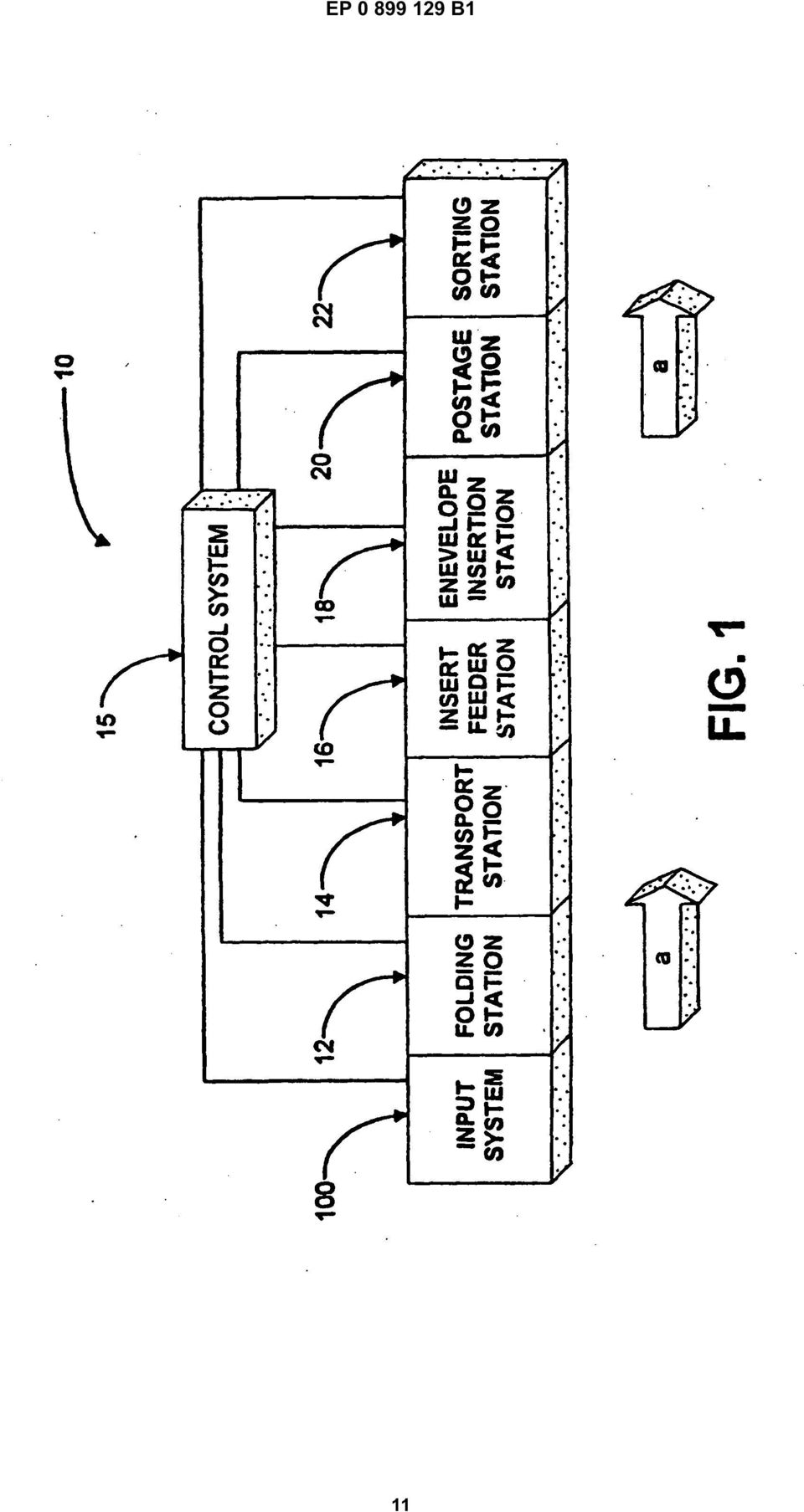
3 3 EP B1 4 feeding module for feeding the two web portions in upperlower relationship so as to reorient the paper web from side-by-side to upper-lower relationship; a separating module located downstream in the path of travel from the merging module for receiving the paper web in the upperlower relationship and separating the paper web into individual sheets in an upper-lower relationship; and a stacking module located downstream in the path of travel from the separating module, the stacking module having an upstream side and downstream side and is configured to receive from the upstream side the individual separated sheets in an upper-lower relationship, stack the individual sheets and individually feed one-up sheets from the stack through the downstream side. [0012] A mass mailing inserter system may include an input system according to said first aspect together with an accumulating module located downstream in the path of travel from the stacking module for collecting a predetermined number of individual one-up sheets in a sheet collation; a folding module located downstream in the path of travel from the accumulating module for folding the sheet collation; and an insertion module located downstream in the path of travel from the folding station for inserting the folded sheet collation into an envelope. [0013] According to a second aspect of the invention, there is provided a method for supplying individual oneup sheets to an inserter system from a web having two portions of travel comprising the steps of: supplying a paper web having two portions in side-by-side relationship; merging the two portions of the web from the sideby-side relationship to an upper-lower relationship; separating the upper-lower relationship paper web into individual two-up sheets; stacking the individual two-up separated sheets in a stacking pile; and feeding from the stacking pile individual one-up sheets. [0014] The above and other objects and advantages of the present invention will become more readily apparent upon consideration of the following detailed description, taken in conjunction with accompanying drawings, in which like reference characters refer to like parts throughout the drawings and in which: Fig. 1 is a block diagram schematic of a document inserting system according to an embodiment of the present invention input system is incorporated; Fig. 2 is a block diagram schematic of an input station according to an embodiment of the invention, for use in the inserter system of Fig. 1; and Fig. 3 is a block diagram schematic of another embodiment of an input system according to the present invention. [001] As described below, the input system includes a feeding module for supplying a paper web having the two web portions in side-by-side relationship. A merging module is located downstream in the path of travel from the feeding module and is operational to feed the two web portions in upper-lower relationship so as to reorient the paper web from the side-by-side relationship to an upper-lower relationship. A separating module is located downstream in the path of travel from the merging module and is operational to receive the paper web in the upperlower relationship and separate the paper web into individual two-up sheets. In order to separate the two-up sheets into one-up sheets, a stacking module is located downstream in the path of travel from the separating module and is configured to receive the two-up sheets, stack the two-up sheets in a sheet pile and individually feed one-up sheets from the stack. [0016] In describing the preferred embodiments of the present invention, reference is made to the drawings, wherein there is seen in FIG. 1 a schematic of a typical document inserting system, generally designated, which includes an input system 0. In the following description, numerous paper handling stations implemented in inserter system are set forth to provide a thorough understanding of the preferred operating environment of the present invention. However it will become apparent to one skilled in the art that the present invention may be practiced without the specific details within the scope of the claims in regard to each of these paper-handling stations. [0017] As will be described in greater detail below system includes an input system 0 that feeds paper sheets from a paper web to an accumulating station that accumulates the sheets of paper in collation packets. Preferably, only a single sheet of a collation is coded (the control document), which coded information enables the control system 1 of inserter system to control the processing of documents in the various stations of the mass mailing inserter system. The code can comprise a bar code, UPC code or the like. [0018] Essentially, input system 0 feeds sheets in a paper path, as indicated by arrow "a," along what is commonly termed the "main deck" of inserter system. After sheets are accumulated into collations by input system 0, the collations are folded in folding station 12 and the folded collations are then conveyed to a transport station 14, preferably operative to perform buffering operations for maintaining a proper timing scheme for the processing of documents in inserting system. [0019] Each sheet collation is fed from transport station 14 to insert feeder station 16. It is to be appreciated that a typical inserter system includes a plurality of feeder stations, but for clarity of illustration only a single insert feeder 16 is shown. Insert feeder station 16 is operational to convey an insert (e.g., an advertisement) from a supply tray to the main deck of inserter system so as to be nested with the aforesaid sheet collation being conveyed along the main deck. The sheet collation and the nested insert(s) are next conveyed into an envelope insertion station 18 that is operative to insert the collation into an envelope. The envelope is then preferably conveyed to postage station that applies appropriate postage thereto. Finally, the envelope is preferably conveyed to sorting station 22 that sorts the envelopes in accordance 3

4 EP B1 6 with postal discount requirements. [00] As previously mentioned, inserter system includes a control system 1 coupled to each modular component of inserter system, which control system 1 controls and harmonizes operation of the various modular components implemented in inserter system. Preferably, control system 1 uses an Optical Character Reader (OCR) for reading the code from each coded document. Such a control system is well known in the art and since it forms no part of the present invention, it is not described in detail in order not to obscure the present disclosure. Similarly, since none of the other above-mentioned modular components (namely: folding station 12, transport station 14, insert feeder station 16. envelope insertion station 18, postage station and sorting station 22) form no part of the present invention input system 0, further discussion of each of these stations is also not described in detail in order not to obscure the present disclosure. Moreover, it is to be appreciated that the depicted embodiment of inserter system including input system 0 is only to be understood as an example configuration of such an inserter system. It is of course to be understood that such an inserter system may have many other configurations in accordance with a specific user s needs. [0021] Referring now to Fig. 2 the input system 0 is shown in more detail. In the preferred embodiment, insert system 0 consists of a paper supply 2, a centerslitting device 6, a merging device 1, a cutting and feed device 114, a stacking and re-feed device 118 and an accumulating device 126. Regarding paper supply device 2, it is to be understood to encompass any known device for supplying side-by-side sheets from a paper web 4 to input system 0 (i.e., enabling a two-up format). Paper supply device 2 may feed the side-by-side web 4 from a web roll, which is well known in the art. Alternatively, paper supply device 2 may feed the sideby-side web 4 from a fan-fold format, also well known in the art. As is typical, web 4 is preferably provided with apertures (not shown) along its side margins for enabling feeding into paper supply station 2, which apertures are subsequently trimmed and discarded. [0022] A center-slit device 6 is coupled to paper supply station 2 and provides a center slitting blade operative to center slit the web 4 into side-by-side uncut sheets 8 (A and B). Coupled to center-slit device 6 is a merging device 1 operative to transfer the centerslit web 8 into an upper-lower relationship, commonly referred to as a "two-up" format 112. That is, merging device 1 merges the two uncut streams of sheets A and B on top of one another, wherein as shown in Fig. 2, the left stream of uncut sheets A are positioned atop the right stream of sheets B producing a "two-up" (A/B) web 112. It is to be appreciated that even though the merging device 1 of Fig. 2 depicts the left side uncut sheets A being positioned atop the right side uncut sheets B (A/B), one skilled in the art could easily adapt merging device to position the right side uncut sheets B atop the left side A uncut sheets (B/A). An example of such a merging device for transforming an uncut web from a side-by-side relationship to an upper-lower relationship can be found in commonly assigned U.S. Patent No.,4,4. [0023] A cutting and feed device 114 is coupled to merging device 1 and is operative to cut the "two-up" A/B web 112 into separated "two-up" (A/B) individual sheets 116. Preferably, cutting and feed device 114 includes either a rotary or guillotine type cutting blade, which cuts the two sheets A and B atop one another 116 every cutter cycle. Preferably, the "two-up" (A/B) sheets 116 are fed from cutting and feed device 114 with a predetermined gap G 1 between each succession of "twoup" (A/B) collations 116 conveying downstream from cutting and feed device 114. It is to be appreciated that in order to maintain a high cycle speed for inserter system, the aforesaid "two-up" (A/B) web 112 is continually transported into cutting and feed device 114 at a constant velocity. [0024] A stacking and re-feed device 118 is coupled in proximity and downstream to cutting and feed device 114 and is operative to separate the "two-up" (A/B) sheet collations 116 into individual sheets 124 (A) and 126 (B). Stacking and re-feed device 118 is needed since the "two-up" (A/B) web 112 is merged before being cut into individual sheets and it is necessary to separate the twoup sheets 116 into individual sheets 122 (A) and 124 (B) prior to further downstream processing in inserter system. In the present preferred embodiment, the two-up sheets 116 (A and B) are separated from one another by stacking the aforesaid "two-up" (A/B) sheet collations 116 atop of one another in a stacking pile 1. Stacking and re-feed device 118 is configured to individually (e.g., in seriatim) feed one-up sheets 122, 124 (A, B) from sheet stack 1. Sheet and re-feed device 118 is further configured to individually re-feed the sheets from the bottom of stack 1 with a predetermined gap G 2 between each successive sheet 122 (A) and 124 (B). This gap G 2 may be varied by stacking and re-feed device 118 under instruction from control system 1, which gap G 2 provides break-points for enabling proper accumulation in downstream accumulating device 126. [002] It is pointed out that another advantage afforded by stacking and re-feed device 118 is that it enables inserter system to maintain a high cycle speed. That is, in order for inserter system to maintain a high cycle speed (e.g., approximately 18,000 mailpieces per hour) it is essential for the input of inserter system 0 to have a considerably greater cycle speed (e.g., approximately 72,000 sheets per hour) due to resulting time requirements needed for subsequent downstream processing (e.g., collating, accumulating, folding, etc). Furthermore, stacking and re-feed device 118 enables sheets to be fed in the aforesaid two-up format 116 from a web roll at an approximately constant speed (e.g., 36,000 cuts per hour) which is also advantageous in that it is difficult to control to the rotational speed of a large web roll (espe- 4

5 7 EP B1 8 cially at high speeds) for feeding sheets therefrom due to the large inertia forces present upon the web roll. The individual sheets 122, 124 (A, B) are then individually fed from stack 1 at a second speed (e.g., over inches per second or 63 cm per second), which second speed is greater than the input speed (e.g., approximately 117 inches per second or 298 cm per second). [0026] Coupled downstream to the stacking and refeed device 118 is an accumulating device 126 for assembling a plurality of individual sheets of paper into a particular desired collation packet prior to further downstream processing. In particular, accumulating device 126 is configured to receive the seriatim fed individual sheets 122 and 124 from stacking and re-feed device 118, and pursuant to instructions by control system 1, collates a predetermined number of sheets 128 before advancing that collation downstream in inserter system for further processing (e.g., folding). Accumulator device 126 may collate the sheets into the desired packets either in the same or reverse order the sheets are fed thereinto. Each collation packet 128 may then be folded, stitched or subsequently combined with other output from document feedings devices located downstream thereof and ultimately inserted into a envelope. It is to be appreciated that such accumulating devices are well known in the art, an example of which is commonly assigned U.S. Patent No.,083,769. [0027] Therefore, an advantage of the present invention mass mailing input system 0 is that it: 1) center slits a web before cutting the web 8 into individual sheets 116; 2) feeds individual sheets 116 at a high speed in a two-up format to a stacking pile 1; and 3) feeds individual sheets 122, 124 (A, B) in seriatim in a one-up format from the stacking pile 1 for subsequent processing in the high speed inserter system. As mentioned above, this system arrangement is particularly advantageous in high-speed inserter systems where it is imperative to provide input sheets at high cycle speeds. In particular, the present invention input system 0 is advantageous in that it eliminates the need for a merging device downstream of the cutting device that results in an additional operation and time. Furthermore, the stacking of individual sheets in stacking and re-feed device 118 acts as a buffer between the accumulating device 126 and the paper supply 2 and provides quick response times to a feed and gap request from the control system 1 while enabling the paper supply 2 to provide a constant feed of documents. [0028] Referring now to Fig. 3, there is shown an input system designated generally by reference numeral 0 that is substantial similar to the above described input system 0, wherein like reference numerals identify like objects. The difference being that stacking and re-feed device 218 of input system 0 is also configured as a "right-angle-turner." That is, stacking and re-feed device 218 changes the direction of travel for sheets 216 feeding from cutting device 114 by 90 relative to sheets 222 feeding from stacking and re-feed device [0029] In operation, and as depicted in Fig. 3, two-up sheets 216 are fed from cutting device 114 into stacking device 218 along a first direction of travel (represented by arrow "A"). As previously mentioned with regard to the stacking device 118 of input system 0, stacking device 218 stacks atop one another the two-up sheets 216 in a sheet pile 2. However, unlike the stacking device 118 of input system 0, stacking device 218 individually feeds, in seriatim, one-up sheets 222 and 224 along a second direction of travel (represented by arrow "B") oriented 90 relative to the aforesaid first direction of travel (represented by arrow "A"). [00] An advantage of this arrangement is that sheets 216 can be fed from a paper supply 2 in a landscape orientation, whereby stacking device 218 changes the sheet orientation to a portrait orientation when sheets 222 are fed downstream from stacking device 218. Of course it is to be appreciated that the input system depicted in Fig. 3 is not to be understood to be limited to changing a sheets orientation of travel from landscape to portrait, as input system 0 may be adapted by one skilled in the art to change a sheets orientation of travel from portrait to landscape. An additionally advantage of input system 0 is that it changes the overall footprint of an inserter system, which is often required so as to suit a customers designated area that is to accommodate the inserter system. [0031] In summary, an input system 0 for providing individual documents to a high speed mass mailing inserter system has been described. Although the present invention has been described with emphasis on a particular embodiment, it should be understood that the Figures are for illustration of the exemplary embodiment of the invention and should not be taken as limitations or thought to be the only means of carrying out the invention. Further, it is contemplated that many changes and modifications may be made to the invention without departing from the scope of the invention as disclosed and claimed. Claims 1. An input system (0) for supplying individually oneup sheets to an inserter system from a paper web (4) having two portions of travel, the input system comprising: a feeding module (2) for supplying the paper web having the two web portions in a side-byside relationship; a merging module (1) located downstream in the path of travel from the feeding module for feeding the two web portions in upper-lower relationship so as to reorient the paper web from side-by-side to upper-lower relationship; a separating module (114) located downstream in the path of travel from the merging module for

6 9 EP B1 receiving the paper web in the upper-lower relationship and separating the paper web into individual sheets in an upper-lower relationship; and a stacking module (118) located downstream in the path of travel from the separating module (114), the stacking module having an upstream side and downstream side and is configured to receive from the upstream side the individual separated sheets in an upper-lower relationship, stack the individual sheets and individually feed one-up sheets from the stack through the downstream side. 2. An input system as recited in Claim 1 further including: an accumulating module (126) located downstream in the path of travel from the stacking module (118) for collecting a predetermined number of individual one-up sheets in a sheet collation. 3. A mass mailing inserter system () having an input system according to Claim 2 for supplying individual one-up sheets from a paper web having two portions of travel, the inserter system further comprising: 1 2 (114) to provide a predetermined spaced gap between each succession of individual sheets in an upper-lower relationship that are being conveyed downstream from the separating module. 8. The system as recited in Claim 7, wherein the stacking module (118) is coupled to the control system (1), which control system is operative to instruct the stacking module to provide a predetermined spaced gap between each individual one-up sheet being conveyed downstream from the stacking module. 9. The system as recited in any preceding claim, wherein the stacking module (118) is operative to receive in the upstream side, in a first velocity, the individual sheets in an upper-lower relationship and convey from the downstream side with a second velocity the individual one-up sheets, wherein the second velocity is greater than the first velocity.. The system as recited in any preceding claim, wherein the stacking module (218) is configured to receive sheets in the upstream side from a first direction of travel and convey sheets from the downstream side in a second direction of travel wherein the second direction of travel is oriented 90 relative to the first direction of travel. a folding module (12) located downstream in the path of travel from the accumulating module (126) for folding the sheet collation; and an insertion module (18) located downstream in the path of travel from the folding station for inserting the folded sheet collation into an envelope. 4. An inserter system as recited in Claim 3, further including: at least one insert feeder module (16) located downstream in the path of travel from the folding station and upstream in the path of travel from the insertion module, the insert feeder module being operative to insert an enclosure into a sheet collation.. The system as recited in any preceding claim, wherein the merging module includes a center mounted slitting blade for separating the paper web having two portions in a side-by-side relationship. 6. The system as recited in any preceding claim, wherein the separating module (114) includes a cutting blade for cutting the web into individual sheets. 7. The system as recited in any preceding claim, wherein the separating module is coupled to a control system (1) operative to instruct the separating module A method for supplying individual one-up sheets to an inserter system from a web having two portions of travel comprising the steps of: supplying a paper web (4; 4) having two portions in side-by-side relationship; merging the two portions of the web from the side-by-side relationship to an upper-lower relationship; separating the upper-lower relationship paper web into individual two-up sheets; stacking the individual two-up separated sheets in a stacking pile; and feeding from the stacking pile individual one-up sheets. 12. A method as recited in Claim 11 further comprising the step: accumulating a predetermined number of oneup sheets in a sheet collation. 13. A method as recited in Claim 11 or 12, wherein the merging step includes the step of center-slitting the paper web having the two web portions in side-byside relationship. 14. A method as recited in any one of Claims 11 to 13, wherein the separating step includes the step of cutting the upper-lower relationship into individual two- 6
 located downstream in the path of travel from the stacking module (118) for collecting a predetermined number of")
7 11 EP B1 12 up sheets. 1. A method as recited in any one of Claims 11 to 14 further including the steps of: providing a first controlled gaped space between each succession of individual two-up sheets; and providing a second controlled gaped space between each individual one-up sheet. 16. A method as recited in any one of Claims 11 to 1, wherein the stacking step includes the step of receiving individual two-up sheets in a first direction of travel; and the feeding step feeds individual one-up sheets in a second direction of travel oriented substantially at 90 relative to the first direction of travel. Patentansprüche 1 ein Sammelmodul (126), das sich in dem Bewegungspfad stromabwärts von dem Stapelmodul (118) befindet, um eine vorbestimmte Anzahl individueller One-up-Blätter in einer Blatt-Zusammenstellung zu sammeln. 3. Massenpost-Einfügesystem () mit einem Eingabesystem nach Anspruch 2 zum Zuführen individueller One-up-Blätter von einer Papierbahn mit zwei Bewegungsabschnitten, wobei das Einfügesystem ferner umfasst: ein Faltmodul (12), das sich im Bewegungspfad stromabwärts von dem Sammelmodul (126) befindet, um die Blatt-Zusammenstellung zu falten; und ein Einfügemodul (18), das sich stromabwärts in dem Bewegungspfad von der Faltstation befindet, um die gefaltete Blatt-Zusammenstellung in eine Briefhülle einzufügen. 1. Eingabesystem (0) zum Zuführen individueller One-up-Blätter von einer Papierbahn (4) mit zwei Bewegungsabschnitten zu einem Einfügesystem, wobei das Eingabesystem umfasst: ein Zufuhrmodul (2) zum Zuführen der Papierbahn mit zwei Bahnabschnitten in einem Nebeneinander-Zusammenhang; ein Zusammenfügemodul (1), das auf dem Bewegungspfad stromabwärts von dem Zufuhrmodul angeordnet ist, zum Zuführen der beiden Bahnabschnitte in einem Oberhalb-Unterhalb- Zusammenhang, um die Papierbahn von dem Nebeneinander-Zusammenhang zu dem Oberhalb-Unterhalb-Zusammenhang umzuorientieren; ein Trennmodul (114), das sich in dem Bewegungspfad stromabwärts von dem Zusammenfügemodul befindet, um die Papierbahn in dem Oberhalb-Unterhalb-Zusammenhang zu empfangen und die Papierbahn in individuelle Blätter in einem Oberhalb-Unterhalb-Zusammenhang zu trennen; und ein Stapelmodul (118), das sich in dem Bewegungspfad stromabwärts von dem Trennmodul (114) befindet, wobei das Stapelmodul eine stromaufwärtige Seite und eine stromabwärtige Seite hat und konfiguriert ist zum Empfangen der individuellen getrennten Blätter von der stromaufwärtigen Seite in einem Oberhalb-Unterhalb-Zusammenhang, zum Stapeln der individuellen Blätter und individuellen zum Befördern von One-up-Blätter von dem Stapel durch die stromabwärtige Seite. 2. Eingabesystem nach Anspruch 1, ferner einschließend: Einfügesystem nach Anspruch 3, ferner einschließend: mindestens ein Einfügezufuhrmodul (16), das sich stromabwärts in dem Bewegungspfad von der Faltstation befindet und stromaufwärts in dem Bewegungspfad von dem Einfügemodul, wobei das Einfügezufuhrmodul betreibbar ist zum Einfügen einer Beilage in eine Blatt-Zusammenstellung.. System nach einem der vorhergehenden Ansprüche, wobei das Zusammenfügemodul eine mittenmontierte Schlitzklinge einschließt zum Trennen der Papierbahn mit zwei Abschnitten in einem Nebeneinander-Zusammenhang. 6. System nach einem der vorhergehenden Ansprüche, wobei das Trennmodul (114) eine Schneidklinge zum Schneiden der Bahn in individuelle Blätter einschließt. 7. System nach einem der vorhergehenden Ansprüche, wobei das Trennmodul an ein Steuersystem (1) gekoppelt ist, das betreibbar ist, um das Trennmodul (114) anzuweisen, einen vorbestimmten beabstandeten Zwischenraum zwischen jedem der aufeinanderfolgenden individuellen Blätter im Oberhalb-Unterhalb-Zusammenhang vorzusehen, die stromabwärts von dem Trennmodul befördert werden. 8. System nach Anspruch 7, wobei das Stapelmodul (118) an das Steuersystem (1) gekoppelt ist, welches Steuersystem betreibbar ist, um das Stapelmodul anzuweisen, einen vorbestimmten beabstandeten Zwischenraum zwischen jeweiligen der strom- 7

8 13 EP B1 14 abwärts von dem Stapelmodul beförderten individuellen One-up-Blätter vorzusehen. 9. System nach einem der vorhergehenden Ansprüche, wobei das Stapelmodul (118) betreibbar ist, um in einer ersten Geschwindigkeit auf der stromaufwärtigen Seite die individuellen Blätter in einem Oberhalb-Unterhalb-Zusammenhang zu empfangen und die individuellen One-up-Blätter von der stromabwärtigen Seite mit einer zweiten Geschwindigkeit zu befördern, wobei die zweite Geschwindigkeit größer ist als die erste Geschwindigkeit.. System nach einem der vorhergehenden Ansprüche, wobei das Stapelmodul (218) konfiguriert ist, um Blätter auf der stromaufwärtigen Seite von einer ersten Bewegungsrichtung zu empfangen und Blätter von der stromabwärtigen Seite in einer zweiten Bewegungsrichtung zu befördern, wobei die zweite Richtung um 90 bezogen auf die erste Bewegungsrichtung ausgerichtet ist. 11. System zum Zuführen individueller One-up-Blätter zu einem Einfügesystem einer Bahn mit zwei Bewegungsabschnitten, die Schritte umfassend: Zuführen einer Papierbahn (4; 4) mit zwei Bewegungsabschnitten in einem Nebeneinander-Zusammenhang; Zusammenfügen der beiden Abschnitte der Bahn von dem Nebeneinander-Zusammenhang zu einem Oberhalb-Unterhalb-Zusammenhang; Trennen der im Oberhalb-Unterhalb-Zusammenhang stehenden Papierbahn in individuelle Two-up-Blätter; Stapeln der individuellen, getrennten Two-up- Blätter in einem Stapel; und Zuführen individueller One-up-Blätter von dem Stapel. 12. Verfahren nach Anspruch 11, ferner den Schritt umfassend: Akkumulieren einer vorbestimmten Anzahl von One-up-Blättern in einer Blatt-Zusammenstellung. 13. Verfahren nach Anspruch 11 oder 12, wobei der Zusammenfüge-Schritt den Schritt des mittigen Auftrennens der Papierbahn mit zwei Papierabschnitten im Nebeneinander-Zusammenhang einschließt. 14. Verfahren nach einem der Ansprüche 11 bis 13, wobei der Trenn-Schritt des Schneidens der individuellen Two-up-Blätter im Oberhalb-Unterhalb-Zusammenhang einschließt Verfahren nach einem der Ansprüche 11 bis 14, ferner die Schritte einschließend: Bereitstellen eines ersten gesteuerten beabstandeten Zwischenraums zwischen jeder Aufeinanderfolge der individuellen Two-up-Blätter; und Bereitstellen eines zweiten gesteuerten beabstandeten Zwischenraums zwischen jeweiligen individuellen One-up-Blättern. 16. Verfahren nach einem der Ansprüche 11 bis 1, wobei der Stapelschritt den Schritt des Empfangens individueller Two-up-Blätter in einer ersten Bewegungsrichtung einschließt und den Zufuhrschritt zum Zuführen individueller One-up-Blätter in einer zweiten Bewegungsrichtung, die 90 in Bezug auf die erste Bewegungsrichtung ausgerichtet ist. Revendications 1. Système d entrée (0) pour délivrer individuellement des feuilles simples à un système d insertion en provenance d une feuille de papier continue (4) ayant deux zones de déplacement, le système d entrée comprenant : un module d entraînement (2) pour délivrer la feuille de papier continue ayant les deux zones de la feuille continue disposées côte à côte ; un module de fusionnement (1) situé en aval sur le trajet de déplacement par rapport au module d entraînement pour entraîner les deux zones de la feuille continue dans une disposition haut-bas de façon à réorienter la feuille de papier continue d une disposition côte à côte à une disposition haut-bas ; un module de séparation (114) situé en aval sur le trajet de déplacement par rapport au module de fusionnement pour recevoir la feuille de papier continue dans la disposition haut-bas et séparer la feuille de papier continue en des feuilles individuelles dans une disposition haut-bas ; et un module d empilage (118) situé en aval sur le trajet de déplacement par rapport au module de séparation (114), le module d empilage ayant un côté amont et un côté aval et étant configuré pour recevoir du côté amont les feuilles individuelles séparées en disposition haut-bas, empiler les feuilles individuelles et introduire individuellement des feuilles simples en provenance de la pile à travers le côté aval. 2. Système d entrée selon la revendication 1, comprenant en outre : un module d accumulation (126) situé en aval sur le trajet de déplacement par rapport au mo- 8

9 1 EP B1 16 dule d empilage (118) pour collecter un nombre prédéterminé de feuilles simples individuelles dans un collationnement de feuilles. 3. Système d insertion de publipostage () ayant un système d entrée selon la revendication 2 pour délivrer des feuilles simples individuelles à partir d une feuille de papier continue ayant deux zones de déplacement, le système d insertion comprenant en outre : vers l aval du module d empilage. 9. Système selon l une quelconque des revendications précédentes, dans lequel le module d empilage (118) a pour fonction de recevoir du côté amont, à une première vitesse, les feuilles individuelles dans une disposition haut-bas et de transporter à partir du côté aval à une deuxième vitesse des feuilles simples individuelles, la deuxième vitesse étant supérieure à la première vitesse. un module de pliage (12) situé en aval sur le trajet de déplacement par rapport au module d accumulation (126) pour plier le collationnement de feuilles ; et un module d insertion (18) situé en aval sur le trajet de déplacement par rapport au poste de pliage pour insérer le collationnement de feuilles pliées dans une enveloppe. 4. Système d insertion selon la revendication 3, comprenant en outre : au moins un module d entraînement d insertion (16) situé en aval sur le trajet de déplacement par rapport au poste de pliage et en amont sur le trajet de déplacement par rapport au module d insertion, le module d entraînement d insertion ayant pour fonction d insérer une pièce jointe dans un collationnement de feuilles.. Système selon l une quelconque des revendications précédentes, dans lequel le module de fusionnement comprend une lame à refendre montée centralement pour séparer la feuille de papier continue comportant deux zones dans une disposition côte à côte. 6. Système selon l une quelconque des revendications précédentes, dans lequel le module de séparation (114) comprend une lame coupante pour découper la feuille continue en des feuilles individuelles. 7. Système selon l une quelconque des revendications précédentes, dans lequel le module de séparation est relié à un système de commande (1) ayant pour fonction d ordonner au module de séparation (114) de produire un interstice d espacement prédéterminé entre chaque succession de feuilles individuelles dans une disposition haut-bas qui sont transportées vers l aval du module de séparation Système selon l une quelconque des revendications précédentes, dans lequel le module d empilage (218) est configuré pour recevoir des feuilles du côté amont dans une première direction de déplacement et de transporter des feuilles provenant du côté aval dans une deuxième direction de déplacement, la deuxième direction de déplacement étant orientée à 90 par rapport à la première direction de déplacement. 11. Procédé pour fournir des feuilles simples individuelles à un système d insertion à partir d une feuille continue ayant deux zones de déplacement, comprenant les étapes consistant à : délivrer une feuille de papier continue (4 ; 4) ayant deux zones disposées côte à côte ; fusionner les deux zones de la feuille continue de la disposition côte à côte à la disposition hautbas ; séparer la feuille de papier continue dans la disposition haut-bas en des feuilles individuelles doubles ; et empiler les feuilles doubles séparées individuelles dans une pile d empilage ; et entraîner depuis la pile d empilage des feuilles simples individuelles. 12. Procédé selon la revendication 11, comprenant en outre l étape : d accumulation d un nombre prédéterminé de feuilles simples dans un collationnement de feuilles. 13. Procédé selon la revendication 11 ou 12, dans lequel l étape de fusionnement comprend l étape de refendage central de la feuille de papier continue ayant deux zones de feuille continue dans une disposition côte à côte. 8. Système selon la revendication 7, dans lequel le module d empilage (118) est relié au système de commande (1), lequel système de commande a pour fonction d ordonner au module d empilage de produire un interstice d espacement prédéterminé entre chaque feuille simple individuelle qui est transportée 14. Procédé selon l une quelconque des revendications 11 à 13, dans lequel l étape de séparation comprend l étape consistant à découper la relation haut-bas en des feuilles doubles individuelles. 1. Procédé selon l une quelconque des revendications 9
 a pour fonction de recevoir du côté amont, à une première vitesse, les feuilles individuelles")
10 17 EP B à 14, comprenant en outre les étapes consistant à: former un premier espace de séparation commandé entre chaque succession de feuilles doubles individuelles ; et former un deuxième espace de séparation commandé entre chaque feuille simple individuelle. 16. Procédé selon l une quelconque des revendications 11 à 1, dans lequel l étape d empilage comprend l étape de réception de feuilles doubles individuelles dans une première direction de déplacement ; et l étape d entraînement entraîne des feuilles simples individuelles dans une deuxième direction de déplacement orientée sensiblement à 90 par rapport à la première direction de déplacement

11 EP B1 11
12 EP B1 12

13 EP B1 13

14 EP B1 REFERENCES CITED IN THE DESCRIPTION This list of references cited by the applicant is for the reader s convenience only. It does not form part of the European patent document. Even though great care has been taken in compiling the references, errors or omissions cannot be excluded and the EPO disclaims all liability in this regard. Patent documents cited in the description US A [0004] US 2676 A [000] US 44 A [0022] US A [0026] 14

*EP001173363B1* EP 1 173 363 B1 (19) (11) EP 1 173 363 B1 (12) EUROPEAN PATENT SPECIFICATION
 (11) EP 1 173 363 B1 (12) EUROPEAN PATENT SPECIFICATION") (19) Europäisches Patentamt European Patent Office Office européen des brevets *EP001173363B1* (11) EP 1 173 363 B1 (12) EUROPEAN PATENT SPECIFICATION (4) Date of publication and mention of the grant of
(19) Europäisches Patentamt European Patent Office Office européen des brevets *EP001173363B1* (11) EP 1 173 363 B1 (12) EUROPEAN PATENT SPECIFICATION (4) Date of publication and mention of the grant of
(51) Int Cl.: G05F 3/26 (2006.01) G05F 3/24 (2006.01)
 Int Cl.: G05F 3/26 (2006.01) G05F 3/24 (2006.01)") (19) Europäisches Patentamt European Patent Office Office européen des brevets (11) EP 1 280 033 B1 (12) EUROPEAN PATENT SPECIFICATION (4) Date of publication and mention of the grant of the patent: 31.0.2006
(19) Europäisches Patentamt European Patent Office Office européen des brevets (11) EP 1 280 033 B1 (12) EUROPEAN PATENT SPECIFICATION (4) Date of publication and mention of the grant of the patent: 31.0.2006
TEPZZ_768 7_B_T EP 1 768 371 B1 (19) (11) EP 1 768 371 B1 (12) EUROPEAN PATENT SPECIFICATION. (51) Int Cl.: H04M 19/04 (2006.01)
 (11) EP 1 768 371 B1 (12) EUROPEAN PATENT SPECIFICATION. (51) Int Cl.: H04M 19/04 (2006.01)") (19) TEPZZ_768 7_B_T (11) EP 1 768 371 B1 (12) EUROPEAN PATENT SPECIFICATION (4) Date of publication and mention of the grant of the patent: 1.01.2014 Bulletin 2014/03 (1) Int Cl.: H04M 19/04 (2006.01)
(19) TEPZZ_768 7_B_T (11) EP 1 768 371 B1 (12) EUROPEAN PATENT SPECIFICATION (4) Date of publication and mention of the grant of the patent: 1.01.2014 Bulletin 2014/03 (1) Int Cl.: H04M 19/04 (2006.01)
(51) Int Cl.: G06F 13/38 (2006.01) G06F 1/16 (2006.01)
 Int Cl.: G06F 13/38 (2006.01) G06F 1/16 (2006.01)") (19) TEPZZ 9777B_T (11) EP 2 97 77 B1 (12) EUROPEAN PATENT SPECIFICATION (4) Date of publication and mention of the grant of the patent: 1.07.1 Bulletin 1/29 (1) Int Cl.: G06F 13/38 (06.01) G06F 1/16 (06.01)
(19) TEPZZ 9777B_T (11) EP 2 97 77 B1 (12) EUROPEAN PATENT SPECIFICATION (4) Date of publication and mention of the grant of the patent: 1.07.1 Bulletin 1/29 (1) Int Cl.: G06F 13/38 (06.01) G06F 1/16 (06.01)
(51) Int Cl.: H04W 4/14 (2009.01)
 Int Cl.: H04W 4/14 (2009.01)") (19) (12) EUROPEAN PATENT SPECIFICATION (11) EP 2 184 897 B1 (4) Date of publication and mention of the grant of the patent: 14.03.12 Bulletin 12/11 (21) Application number: 087774.3 (22) Date of filing:
(19) (12) EUROPEAN PATENT SPECIFICATION (11) EP 2 184 897 B1 (4) Date of publication and mention of the grant of the patent: 14.03.12 Bulletin 12/11 (21) Application number: 087774.3 (22) Date of filing:
(51) Int Cl.: H04L 29/06 (2006.01) G06F 9/445 (2006.01) G06F 13/00 (2006.01)
 Int Cl.: H04L 29/06 (2006.01) G06F 9/445 (2006.01) G06F 13/00 (2006.01)") (19) TEPZZ_7486_6B_T (11) EP 1 748 616 B1 (12) EUROPEAN PATENT SPECIFICATION (4) Date of publication and mention of the grant of the patent: 03.09.2014 Bulletin 2014/36 (1) Int Cl.: H04L 29/06 (2006.01)
(19) TEPZZ_7486_6B_T (11) EP 1 748 616 B1 (12) EUROPEAN PATENT SPECIFICATION (4) Date of publication and mention of the grant of the patent: 03.09.2014 Bulletin 2014/36 (1) Int Cl.: H04L 29/06 (2006.01)
(51) Int Cl.: H05K 1/02 (2006.01)
 Int Cl.: H05K 1/02 (2006.01)") (19) (11) EP 1 229 767 B1 (12) EUROPEAN PATENT SPECIFICATION (4) Date of publication and mention of the grant of the patent: 20.01.2010 Bulletin 2010/03 (1) Int Cl.: H0K 1/02 (2006.01) (21) Application
(19) (11) EP 1 229 767 B1 (12) EUROPEAN PATENT SPECIFICATION (4) Date of publication and mention of the grant of the patent: 20.01.2010 Bulletin 2010/03 (1) Int Cl.: H0K 1/02 (2006.01) (21) Application
(51) Int Cl. 7 : G03G 15/00
 Int Cl. 7 : G03G 15/00") (19) Europäisches Patentamt European Patent Office Office européen des brevets *EP001179B1* (11) EP 1 17 9 B1 (12) EUROPEAN PATENT SPECIFICATION (4) Date of publication and mention of the grant of the
(19) Europäisches Patentamt European Patent Office Office européen des brevets *EP001179B1* (11) EP 1 17 9 B1 (12) EUROPEAN PATENT SPECIFICATION (4) Date of publication and mention of the grant of the
(51) Int Cl.: B65H 9/16 (2006.01) B65H 5/02 (2006.01)
 Int Cl.: B65H 9/16 (2006.01) B65H 5/02 (2006.01)") (19) (11) EP 1 4 6 B1 (12) EUROPEAN PATENT SPECIFICATION (4) Date of publication and mention of the grant of the patent: 17.09.08 Bulletin 08/38 (1) Int Cl.: B6H 9/16 (06.01) B6H /02 (06.01) (21) Application
(19) (11) EP 1 4 6 B1 (12) EUROPEAN PATENT SPECIFICATION (4) Date of publication and mention of the grant of the patent: 17.09.08 Bulletin 08/38 (1) Int Cl.: B6H 9/16 (06.01) B6H /02 (06.01) (21) Application
(51) Int Cl.: H04L 12/26 (2006.01)
 Int Cl.: H04L 12/26 (2006.01)") (19) TEPZZ 84 8B_T (11) EP 2 84 338 B1 (12) EUROPEAN PATENT SPECIFICATION (4) Date of publication and mention of the grant of the patent: 23.09.1 Bulletin 1/39 (1) Int Cl.: H04L 12/26 (06.01) (21) Application
(19) TEPZZ 84 8B_T (11) EP 2 84 338 B1 (12) EUROPEAN PATENT SPECIFICATION (4) Date of publication and mention of the grant of the patent: 23.09.1 Bulletin 1/39 (1) Int Cl.: H04L 12/26 (06.01) (21) Application
(51) Int Cl.: H04N 7/16 (2011.01)
 Int Cl.: H04N 7/16 (2011.01)") (19) TEPZZ_796 89B_T (11) EP 1 796 389 B1 (12) EUROPEAN PATENT SPECIFICATION (4) Date of publication and mention of the grant of the patent: 04.03.1 Bulletin 1/ (1) Int Cl.: H04N 7/16 (11.01) (21) Application
(19) TEPZZ_796 89B_T (11) EP 1 796 389 B1 (12) EUROPEAN PATENT SPECIFICATION (4) Date of publication and mention of the grant of the patent: 04.03.1 Bulletin 1/ (1) Int Cl.: H04N 7/16 (11.01) (21) Application
(51) Int Cl.: C08K 5/523 (2006.01) C08K 5/521 (2006.01) C08K 5/52 (2006.01) C08G 64/00 (2006.01)
 Int Cl.: C08K 5/523 (2006.01) C08K 5/521 (2006.01) C08K 5/52 (2006.01) C08G 64/00 (2006.01)") (19) Europäisches Patentamt European Patent Office Office européen des brevets (11) EP 0 78 966 B1 (12) EUROPEAN PATENT SPECIFICATION (4) Date of publication and mention of the grant of the patent: 01.03.06
(19) Europäisches Patentamt European Patent Office Office européen des brevets (11) EP 0 78 966 B1 (12) EUROPEAN PATENT SPECIFICATION (4) Date of publication and mention of the grant of the patent: 01.03.06
(51) Int Cl.: G06F 21/00 (2006.01) H04L 29/06 (2006.01)
 Int Cl.: G06F 21/00 (2006.01) H04L 29/06 (2006.01)") (19) TEPZZ_8Z_7 _B_T (11) EP 1 801 721 B1 (12) EUROPEAN PATENT SPECIFICATION (4) Date of publication and mention of the grant of the patent: 16.06. Bulletin /24 (1) Int Cl.: G06F 21/00 (06.01) H04L 29/06
(19) TEPZZ_8Z_7 _B_T (11) EP 1 801 721 B1 (12) EUROPEAN PATENT SPECIFICATION (4) Date of publication and mention of the grant of the patent: 16.06. Bulletin /24 (1) Int Cl.: G06F 21/00 (06.01) H04L 29/06
(51) Int Cl.: H04L 12/24 (2006.01)
 Int Cl.: H04L 12/24 (2006.01)") (19) TEPZZ_8_9Z96B_T (11) EP 1 819 096 B1 (12) EUROPEAN PATENT SPECIFICATION (4) Date of publication and mention of the grant of the patent: 24..12 Bulletin 12/43 (21) Application number: 0818628.9 (22)
(19) TEPZZ_8_9Z96B_T (11) EP 1 819 096 B1 (12) EUROPEAN PATENT SPECIFICATION (4) Date of publication and mention of the grant of the patent: 24..12 Bulletin 12/43 (21) Application number: 0818628.9 (22)
(51) Int Cl.: H04N 5/225 (2006.01)
 Int Cl.: H04N 5/225 (2006.01)") (19) TEPZZ_94 66_B_T (11) EP 1 942 661 B1 (12) EUROPEAN PATENT SPECIFICATION (4) Date of publication and mention of the grant of the patent: 17.09.2014 Bulletin 2014/38 (1) Int Cl.: H04N /22 (2006.01)
(19) TEPZZ_94 66_B_T (11) EP 1 942 661 B1 (12) EUROPEAN PATENT SPECIFICATION (4) Date of publication and mention of the grant of the patent: 17.09.2014 Bulletin 2014/38 (1) Int Cl.: H04N /22 (2006.01)
TEPZZ 5Z _9_B_T EP 2 502 191 B1 (19) (11) EP 2 502 191 B1 (12) EUROPEAN PATENT SPECIFICATION
 (11) EP 2 502 191 B1 (12) EUROPEAN PATENT SPECIFICATION") (19) TEPZZ Z _9_B_T (11) EP 2 02 191 B1 (12) EUROPEAN PATENT SPECIFICATION (4) Date of publication and mention of the grant of the patent: 17.06.1 Bulletin 1/2 (21) Application number: 787872.0 (22) Date
(19) TEPZZ Z _9_B_T (11) EP 2 02 191 B1 (12) EUROPEAN PATENT SPECIFICATION (4) Date of publication and mention of the grant of the patent: 17.06.1 Bulletin 1/2 (21) Application number: 787872.0 (22) Date
(51) Int Cl.: H04L 29/06 (2006.01) H04Q 7/24 (2006.01) H04L 12/66 (2006.01)
 Int Cl.: H04L 29/06 (2006.01) H04Q 7/24 (2006.01) H04L 12/66 (2006.01)") (19) (11) EP 1 314 291 B1 (12) EUROPEAN PATENT SPECIFICATION (4) Date of publication and mention of the grant of the patent:..07 Bulletin 07/41 (21) Application number: 0194907.2 (22) Date of filing: 06.07.01
(19) (11) EP 1 314 291 B1 (12) EUROPEAN PATENT SPECIFICATION (4) Date of publication and mention of the grant of the patent:..07 Bulletin 07/41 (21) Application number: 0194907.2 (22) Date of filing: 06.07.01
The Advantialer and Its Advantages
 (19) TEPZZ Z B_T (11) EP 2 0 113 B1 (12) EUROPEAN PATENT SPECIFICATION (4) Date of publication and mention of the grant of the patent: 16.09.1 Bulletin 1/38 (21) Application number: 07809477.8 (22) Date
(51) Int Cl.: G06F 1/00 (2006.01)
 Int Cl.: G06F 1/00 (2006.01)") (19) (11) EP 0 972 234 B1 (12) EUROPEAN PATENT SPECIFICATION (4) Date of publication and mention of the grant of the patent: 0.09.07 Bulletin 07/36 (21) Application number: 98913219.6 (22) Date of filing:
(19) (11) EP 0 972 234 B1 (12) EUROPEAN PATENT SPECIFICATION (4) Date of publication and mention of the grant of the patent: 0.09.07 Bulletin 07/36 (21) Application number: 98913219.6 (22) Date of filing:
(51) Int Cl.: G06Q 10/00 (2006.01)
 Int Cl.: G06Q 10/00 (2006.01)") (19) (11) EP 1 69 282 B1 (12) EUROPEAN PATENT SPECIFICATION (4) Date of publication and mention of the grant of the patent: 2.03.09 Bulletin 09/13 (21) Application number: 048.1 (22) Date of filing: 29.11.04
(19) (11) EP 1 69 282 B1 (12) EUROPEAN PATENT SPECIFICATION (4) Date of publication and mention of the grant of the patent: 2.03.09 Bulletin 09/13 (21) Application number: 048.1 (22) Date of filing: 29.11.04
TEPZZ_9 6Z46B_T EP 1 926 046 B1 (19) (11) EP 1 926 046 B1 (12) EUROPEAN PATENT SPECIFICATION. (51) Int Cl.:
 (11) EP 1 926 046 B1 (12) EUROPEAN PATENT SPECIFICATION. (51) Int Cl.:") (19) TEPZZ_9 6Z46B_T (11) EP 1 926 046 B1 (12) EUROPEAN PATENT SPECIFICATION (4) Date of publication and mention of the grant of the patent: 21.08.13 Bulletin 13/34 (1) Int Cl.: G06F 19/00 (11.01) (21)
(19) TEPZZ_9 6Z46B_T (11) EP 1 926 046 B1 (12) EUROPEAN PATENT SPECIFICATION (4) Date of publication and mention of the grant of the patent: 21.08.13 Bulletin 13/34 (1) Int Cl.: G06F 19/00 (11.01) (21)
(51) Int Cl.: G10L 15/26 (2006.01)
 Int Cl.: G10L 15/26 (2006.01)") (19) TEPZZ Z 8B_T (11) EP 2 023 338 B1 (12) EUROPEAN PATENT SPECIFICATION (4) Date of publication and mention of the grant of the patent: 28.0.14 Bulletin 14/22 (1) Int Cl.: GL /26 (06.01) (21) Application
(19) TEPZZ Z 8B_T (11) EP 2 023 338 B1 (12) EUROPEAN PATENT SPECIFICATION (4) Date of publication and mention of the grant of the patent: 28.0.14 Bulletin 14/22 (1) Int Cl.: GL /26 (06.01) (21) Application
(51) Int Cl.: B29C 41/20 (2006.01) F21S 4/00 (2006.01) H05K 3/28 (2006.01)
 Int Cl.: B29C 41/20 (2006.01) F21S 4/00 (2006.01) H05K 3/28 (2006.01)") (19) TEPZZ 68698B_T (11) EP 2 68 698 B1 (12) EUROPEAN PATENT SPECIFICATION (4) Date of publication and mention of the grant of the patent: 18.11.201 Bulletin 201/47 (21) Application number: 11808612.3
(19) TEPZZ 68698B_T (11) EP 2 68 698 B1 (12) EUROPEAN PATENT SPECIFICATION (4) Date of publication and mention of the grant of the patent: 18.11.201 Bulletin 201/47 (21) Application number: 11808612.3
(51) Int Cl.: G06F 21/24 (2006.01)
 Int Cl.: G06F 21/24 (2006.01)") (19) (12) EUROPEAN PATENT SPECIFICATION (11) EP 1 674 960 B1 (45) Date of publication and mention of the grant of the patent: 05..2011 Bulletin 2011/40 (51) Int Cl.: G06F 21/24 (2006.01) (21) Application
(19) (12) EUROPEAN PATENT SPECIFICATION (11) EP 1 674 960 B1 (45) Date of publication and mention of the grant of the patent: 05..2011 Bulletin 2011/40 (51) Int Cl.: G06F 21/24 (2006.01) (21) Application
(51) Int Cl.: H04L 12/58 (2006.01)
 Int Cl.: H04L 12/58 (2006.01)") (19) (11) EP 1 628 448 B1 (12) EUROPEAN PATENT SPECIFICATION (4) Date of publication and mention of the grant of the patent: 21.11.07 Bulletin 07/47 (1) Int Cl.: H04L 12/8 (06.01) (21) Application number:
(19) (11) EP 1 628 448 B1 (12) EUROPEAN PATENT SPECIFICATION (4) Date of publication and mention of the grant of the patent: 21.11.07 Bulletin 07/47 (1) Int Cl.: H04L 12/8 (06.01) (21) Application number:
(51) Int Cl.: H01M 8/04 (2006.01)
 Int Cl.: H01M 8/04 (2006.01)") (19) (11) EP 1 791 20 B1 (12) EUROPEAN PATENT SPECIFICATION (4) Date of publication and mention of the grant of the patent: 12.09.2012 Bulletin 2012/37 (1) Int Cl.: H01M 8/04 (2006.01) (21) Application
(19) (11) EP 1 791 20 B1 (12) EUROPEAN PATENT SPECIFICATION (4) Date of publication and mention of the grant of the patent: 12.09.2012 Bulletin 2012/37 (1) Int Cl.: H01M 8/04 (2006.01) (21) Application
(51) Int Cl.: H04M 3/50 (2006.01)
 Int Cl.: H04M 3/50 (2006.01)") (19) TEPZZ_Z48_64B_T (11) EP 1 048 164 B1 (12) EUROPEAN PATENT SPECIFICATION (4) Date of publication and mention of the grant of the patent: 07.01.1 Bulletin 1/02 (21) Application number: 9893133.0 (22)
(19) TEPZZ_Z48_64B_T (11) EP 1 048 164 B1 (12) EUROPEAN PATENT SPECIFICATION (4) Date of publication and mention of the grant of the patent: 07.01.1 Bulletin 1/02 (21) Application number: 9893133.0 (22)
(51) Int Cl.: H04L 12/66 (2006.01)
 Int Cl.: H04L 12/66 (2006.01)") (19) (12) EUROPEAN PATENT SPECIFICATION (11) EP 1 73 43 B1 (4) Date of publication and mention of the grant of the patent: 18.01.12 Bulletin 12/03 (21) Application number: 02792. (22) Date of filing: 26.12.02
(19) (12) EUROPEAN PATENT SPECIFICATION (11) EP 1 73 43 B1 (4) Date of publication and mention of the grant of the patent: 18.01.12 Bulletin 12/03 (21) Application number: 02792. (22) Date of filing: 26.12.02
(51) Int Cl.: H04L 29/06 (2006.01) H04L 12/22 (2006.01)
 Int Cl.: H04L 29/06 (2006.01) H04L 12/22 (2006.01)") (19) (11) EP 0 998 091 B1 (12) EUROPEAN PATENT SPECIFICATION (4) Date of publication and mention of the grant of the patent: 31.01.07 Bulletin 07/0 (1) Int Cl.: H04L 29/06 (06.01) H04L 12/22 (06.01) (21)
(19) (11) EP 0 998 091 B1 (12) EUROPEAN PATENT SPECIFICATION (4) Date of publication and mention of the grant of the patent: 31.01.07 Bulletin 07/0 (1) Int Cl.: H04L 29/06 (06.01) H04L 12/22 (06.01) (21)
(51) Int Cl.: G06F 17/30 (2006.01)
 Int Cl.: G06F 17/30 (2006.01)") (19) TEPZZ 7 _B_T (11) EP 1 127 321 B1 (12) EUROPEAN PATENT SPECIFICATION (4) Date of publication and mention of the grant of the patent: 03.04.13 Bulletin 13/14 (21) Application number: 99948341. (22)
(19) TEPZZ 7 _B_T (11) EP 1 127 321 B1 (12) EUROPEAN PATENT SPECIFICATION (4) Date of publication and mention of the grant of the patent: 03.04.13 Bulletin 13/14 (21) Application number: 99948341. (22)
(51) Int Cl. 7 : G06F 11/22
 Int Cl. 7 : G06F 11/22") (19) Europäisches Patentamt European Patent Office Office européen des brevets *EP00084463B1* (11) EP 0 844 63 B1 (12) EUROPEAN PATENT SPECIFICATION (4) Date of publication and mention of the grant of
(19) Europäisches Patentamt European Patent Office Office européen des brevets *EP00084463B1* (11) EP 0 844 63 B1 (12) EUROPEAN PATENT SPECIFICATION (4) Date of publication and mention of the grant of
(51) Int Cl.: H04L 12/24 (2006.01) G06F 9/445 (2006.01)
 Int Cl.: H04L 12/24 (2006.01) G06F 9/445 (2006.01)") (19) (12) EUROPEAN PATENT SPECIFICATION (11) EP 1 978 672 B1 (4) Date of publication and mention of the grant of the patent: 01.09. Bulletin /3 (1) Int Cl.: H04L 12/24 (06.01) G06F 9/44 (06.01) (21) Application
(19) (12) EUROPEAN PATENT SPECIFICATION (11) EP 1 978 672 B1 (4) Date of publication and mention of the grant of the patent: 01.09. Bulletin /3 (1) Int Cl.: H04L 12/24 (06.01) G06F 9/44 (06.01) (21) Application
(51) Int Cl.: H04M 3/42 (2006.01) H04Q 3/00 (2006.01)
 Int Cl.: H04M 3/42 (2006.01) H04Q 3/00 (2006.01)") (19) (11) EP 1 696 646 B1 (12) EUROPEAN PATENT SPECIFICATION (4) Date of publication and mention of the grant of the patent: 07.03.12 Bulletin 12/ (1) Int Cl.: H04M 3/42 (06.01) H04Q 3/00 (06.01) (21)
(19) (11) EP 1 696 646 B1 (12) EUROPEAN PATENT SPECIFICATION (4) Date of publication and mention of the grant of the patent: 07.03.12 Bulletin 12/ (1) Int Cl.: H04M 3/42 (06.01) H04Q 3/00 (06.01) (21)
(51) Int Cl.: H04L 29/06 (2006.01) H04M 3/56 (2006.01) H04M 3/44 (2006.01) H04L 12/18 (2006.01)
 Int Cl.: H04L 29/06 (2006.01) H04M 3/56 (2006.01) H04M 3/44 (2006.01) H04L 12/18 (2006.01)") (19) TEPZZ Z9 79B_T (11) EP 2 091 179 B1 (12) EUROPEAN PATENT SPECIFICATION (4) Date of publication and mention of the grant of the patent: 17.12.14 Bulletin 14/1 (21) Application number: 07817029.7 (22)
(19) TEPZZ Z9 79B_T (11) EP 2 091 179 B1 (12) EUROPEAN PATENT SPECIFICATION (4) Date of publication and mention of the grant of the patent: 17.12.14 Bulletin 14/1 (21) Application number: 07817029.7 (22)
(51) Int Cl. 7 : H04B 7/185, H04B 1/40. (56) References cited: WO-A-00/03494
 Int Cl. 7 : H04B 7/185, H04B 1/40. (56) References cited: WO-A-00/03494") (19) Europäisches Patentamt European Patent Office Office européen des brevets *EP001363412B1* (11) EP 1 363 412 B1 (12) EUROPEAN PATENT SPECIFICATION (4) Date of publication and mention of the grant of
(19) Europäisches Patentamt European Patent Office Office européen des brevets *EP001363412B1* (11) EP 1 363 412 B1 (12) EUROPEAN PATENT SPECIFICATION (4) Date of publication and mention of the grant of
(51) Int Cl.: H04L 9/24 (2006.01) G06Q 10/00 (2012.01)
 Int Cl.: H04L 9/24 (2006.01) G06Q 10/00 (2012.01)") (19) TEPZZ_4Z 68ZB_T (11) EP 1 2 680 B1 (12) EUROPEAN PATENT SPECIFICATION (4) Date of publication and mention of the grant of the patent: 01.04.1 Bulletin 1/14 (21) Application number: 02741722.9 (22)
(19) TEPZZ_4Z 68ZB_T (11) EP 1 2 680 B1 (12) EUROPEAN PATENT SPECIFICATION (4) Date of publication and mention of the grant of the patent: 01.04.1 Bulletin 1/14 (21) Application number: 02741722.9 (22)
(51) Int Cl.: H04L 12/56 (2006.01) H04L 12/28 (2006.01) H04M 7/00 (2006.01)
 Int Cl.: H04L 12/56 (2006.01) H04L 12/28 (2006.01) H04M 7/00 (2006.01)") (19) (12) EUROPEAN PATENT SPECIFICATION (11) EP 1 129 0 B1 (4) Date of publication and mention of the grant of the patent: 09.04.08 Bulletin 08/1 (21) Application number: 9996836.2 (22) Date of filing:
(19) (12) EUROPEAN PATENT SPECIFICATION (11) EP 1 129 0 B1 (4) Date of publication and mention of the grant of the patent: 09.04.08 Bulletin 08/1 (21) Application number: 9996836.2 (22) Date of filing:
(51) Int Cl.: H05K 1/02 (2006.01)
 Int Cl.: H05K 1/02 (2006.01)") (19) TEPZZ 4 67B_T (11) EP 2 241 167 B1 (12) EUROPEAN PATENT SPECIFICATION (4) Date of publication and mention of the grant of the patent:.03.13 Bulletin 13/12 (21) Application number: 0886976.0 (22) Date
(19) TEPZZ 4 67B_T (11) EP 2 241 167 B1 (12) EUROPEAN PATENT SPECIFICATION (4) Date of publication and mention of the grant of the patent:.03.13 Bulletin 13/12 (21) Application number: 0886976.0 (22) Date
(51) Int Cl.: B65D 1/26 (2006.01) B31B 43/00 (2006.01) B65D 1/34 (2006.01) B21D 22/20 (2006.01) B21D 51/18 (2006.01)
 Int Cl.: B65D 1/26 (2006.01) B31B 43/00 (2006.01) B65D 1/34 (2006.01) B21D 22/20 (2006.01) B21D 51/18 (2006.01)") (19) TEPZZ 4779ZZB_T (11) EP 2 477 900 B1 (12) EUROPEAN PATENT SPECIFICATION (4) Date of publication and mention of the grant of the patent: 12.08.20 Bulletin 20/33 (21) Application number: 776.8 (22)
(19) TEPZZ 4779ZZB_T (11) EP 2 477 900 B1 (12) EUROPEAN PATENT SPECIFICATION (4) Date of publication and mention of the grant of the patent: 12.08.20 Bulletin 20/33 (21) Application number: 776.8 (22)
(51) Int Cl.: G08G 1/14 (2006.01) G07B 15/02 (2006.01) G10L 15/28 (2006.01)
 Int Cl.: G08G 1/14 (2006.01) G07B 15/02 (2006.01) G10L 15/28 (2006.01)") (19) (12) EUROPEAN PATENT SPECIFICATION (11) EP 1 862 986 B1 (4) Date of publication and mention of the grant of the patent: 14.07. Bulletin /28 (1) Int Cl.: G08G 1/14 (06.01) G07B 1/02 (06.01) GL 1/28
(19) (12) EUROPEAN PATENT SPECIFICATION (11) EP 1 862 986 B1 (4) Date of publication and mention of the grant of the patent: 14.07. Bulletin /28 (1) Int Cl.: G08G 1/14 (06.01) G07B 1/02 (06.01) GL 1/28
(51) Int Cl.: G06F 9/46 (2006.01) H04L 12/56 (2006.01)
 Int Cl.: G06F 9/46 (2006.01) H04L 12/56 (2006.01)") (19) (11) EP 1 611 23 B1 (12) EUROPEAN PATENT SPECIFICATION (4) Date of publication and mention of the grant of the patent: 21.0.08 Bulletin 08/21 (21) Application number: 0471948.2 (22) Date of filing:
(19) (11) EP 1 611 23 B1 (12) EUROPEAN PATENT SPECIFICATION (4) Date of publication and mention of the grant of the patent: 21.0.08 Bulletin 08/21 (21) Application number: 0471948.2 (22) Date of filing:
(51) Int Cl.: G08B 21/02 (2006.01) H04M 11/04 (2006.01)
 Int Cl.: G08B 21/02 (2006.01) H04M 11/04 (2006.01)") (19) Europäisches Patentamt European Patent Office Office européen des brevets (11) EP 1 224 642 B1 (12) EUROPEAN PATENT SPECIFICATION (4) Date of publication and mention of the grant of the patent: 1.03.06
(19) Europäisches Patentamt European Patent Office Office européen des brevets (11) EP 1 224 642 B1 (12) EUROPEAN PATENT SPECIFICATION (4) Date of publication and mention of the grant of the patent: 1.03.06
(51) Int Cl.: H04L 12/56 (2006.01)
 Int Cl.: H04L 12/56 (2006.01)") (19) (11) EP 1 779 90 B1 (12) EUROPEAN PATENT SPECIFICATION (4) Date of publication and mention of the grant of the patent: 28.12.11 Bulletin 11/2 (21) Application number: 0783482.2 (22) Date of filing:
(19) (11) EP 1 779 90 B1 (12) EUROPEAN PATENT SPECIFICATION (4) Date of publication and mention of the grant of the patent: 28.12.11 Bulletin 11/2 (21) Application number: 0783482.2 (22) Date of filing:
(51) Int Cl.: H04L 9/32 (2006.01) H04B 7/00 (2006.01) A61N 1/37 (2006.01)
 Int Cl.: H04L 9/32 (2006.01) H04B 7/00 (2006.01) A61N 1/37 (2006.01)") (19) TEPZZ_4977B_T (11) EP 1 49 77 B1 (12) EUROPEAN PATENT SPECIFICATION (4) Date of publication and mention of the grant of the patent:.12.14 Bulletin 14/0 (21) Application number: 03723989.4 (22) Date
(19) TEPZZ_4977B_T (11) EP 1 49 77 B1 (12) EUROPEAN PATENT SPECIFICATION (4) Date of publication and mention of the grant of the patent:.12.14 Bulletin 14/0 (21) Application number: 03723989.4 (22) Date
(51) Int Cl.: G05B 19/05 (2006.01)
 Int Cl.: G05B 19/05 (2006.01)") (19) (11) EP 1 291 74 B1 (12) EUROPEAN PATENT SPECIFICATION (4) Date of publication and mention of the grant of the patent:.06.07 Bulletin 07/2 (1) Int Cl.: G0B 19/0 (06.01) (21) Application number: 078479.9
(19) (11) EP 1 291 74 B1 (12) EUROPEAN PATENT SPECIFICATION (4) Date of publication and mention of the grant of the patent:.06.07 Bulletin 07/2 (1) Int Cl.: G0B 19/0 (06.01) (21) Application number: 078479.9
(51) Int Cl.: H04L 12/24 (2006.01)
 Int Cl.: H04L 12/24 (2006.01)") (19) (12) EUROPEAN PATENT SPECIFICATION (11) EP 1 487 11 B1 (4) Date of publication and mention of the grant of the patent: 01.07.09 Bulletin 09/27 (1) Int Cl.: H04L 12/24 (06.01) (21) Application number:
(19) (12) EUROPEAN PATENT SPECIFICATION (11) EP 1 487 11 B1 (4) Date of publication and mention of the grant of the patent: 01.07.09 Bulletin 09/27 (1) Int Cl.: H04L 12/24 (06.01) (21) Application number:
(51) Int Cl.: B61K 9/12 (2006.01)
 Int Cl.: B61K 9/12 (2006.01)") (19) (11) EP 2 001 722 B1 (12) EUROPEAN PATENT SPECIFICATION (4) Date of publication and mention of the grant of the patent: 21.12.11 Bulletin 11/1 (21) Application number: 077926.6 (22) Date of filing:
(19) (11) EP 2 001 722 B1 (12) EUROPEAN PATENT SPECIFICATION (4) Date of publication and mention of the grant of the patent: 21.12.11 Bulletin 11/1 (21) Application number: 077926.6 (22) Date of filing:
(51) Int Cl.: H04L 29/06 (2006.01) H04M 15/00 (2006.01)
 Int Cl.: H04L 29/06 (2006.01) H04M 15/00 (2006.01)") (19) TEPZZ 7Z 74 B_T (11) EP 2 702 742 B1 (12) EUROPEAN PATENT SPECIFICATION (4) Date of publication and mention of the grant of the patent:.04. Bulletin /16 (21) Application number: 1171674.6 (22) Date
(19) TEPZZ 7Z 74 B_T (11) EP 2 702 742 B1 (12) EUROPEAN PATENT SPECIFICATION (4) Date of publication and mention of the grant of the patent:.04. Bulletin /16 (21) Application number: 1171674.6 (22) Date
(51) Int Cl.: H04B 3/23 (2006.01)
 Int Cl.: H04B 3/23 (2006.01)") (19) (11) EP 0 983 638 B1 (12) EUROPEAN PATENT SPECIFICATION (4) Date of publication and mention of the grant of the patent: 21.03.12 Bulletin 12/12 (21) Application number: 989232.7 (22) Date of filing:
(19) (11) EP 0 983 638 B1 (12) EUROPEAN PATENT SPECIFICATION (4) Date of publication and mention of the grant of the patent: 21.03.12 Bulletin 12/12 (21) Application number: 989232.7 (22) Date of filing:
(51) Int Cl.: H04L 29/08 (2006.01) H04L 29/06 (2006.01)
 Int Cl.: H04L 29/08 (2006.01) H04L 29/06 (2006.01)") (19) TEPZZ_897 6B_T (11) EP 1 897 336 B1 (12) EUROPEAN PATENT SPECIFICATION (4) Date of publication and mention of the grant of the patent: 12.08.1 Bulletin 1/33 (21) Application number: 06779738.1 (22)
(19) TEPZZ_897 6B_T (11) EP 1 897 336 B1 (12) EUROPEAN PATENT SPECIFICATION (4) Date of publication and mention of the grant of the patent: 12.08.1 Bulletin 1/33 (21) Application number: 06779738.1 (22)
(51) Int Cl.: H04N 7/15 (2006.01) H04N 7/18 (2006.01)
 Int Cl.: H04N 7/15 (2006.01) H04N 7/18 (2006.01)") (19) TEPZZ_4967ZZB_T (11) EP 1 496 700 B1 (12) EUROPEAN PATENT SPECIFICATION (4) Date of publication and mention of the grant of the patent: 1.01.14 Bulletin 14/03 (1) Int Cl.: H04N 7/1 (06.01) H04N 7/18
(19) TEPZZ_4967ZZB_T (11) EP 1 496 700 B1 (12) EUROPEAN PATENT SPECIFICATION (4) Date of publication and mention of the grant of the patent: 1.01.14 Bulletin 14/03 (1) Int Cl.: H04N 7/1 (06.01) H04N 7/18
Office europeen des brevets Publication number: 0 377 486 B1 EUROPEAN PATENT SPECIFICATION
 Office europeen des brevets Publication number: 0 377 486 B1 EUROPEAN PATENT SPECIFICATION Date of publication of patent specification : Int. CI.5 : F16L 58/10, F16L 55/16 21.07.93 Bulletin 93/29 Application
(51) Int Cl. 7 : F16K 11/044, F16K 11/04
 Int Cl. 7 : F16K 11/044, F16K 11/04") (19) Europäisches Patentamt European Patent Office Office européen des brevets *EP0078182B1* (11) EP 1 078 182 B1 (12) EUROPEAN PATENT SPECIFICATION (4) Date of publication and mention of the grant of
(19) Europäisches Patentamt European Patent Office Office européen des brevets *EP0078182B1* (11) EP 1 078 182 B1 (12) EUROPEAN PATENT SPECIFICATION (4) Date of publication and mention of the grant of
(51) Int Cl.: H04W 8/16 (2009.01) H04L 29/12 (2006.01) H04W 8/18 (2009.01)
 Int Cl.: H04W 8/16 (2009.01) H04L 29/12 (2006.01) H04W 8/18 (2009.01)") (19) TEPZZ 474_77B_T (11) EP 2 474 177 B1 (12) EUROPEAN PATENT SPECIFICATION (4) Date of publication and mention of the grant of the patent: 0.11.14 Bulletin 14/4 (21) Application number: 747648.3 (22)
(19) TEPZZ 474_77B_T (11) EP 2 474 177 B1 (12) EUROPEAN PATENT SPECIFICATION (4) Date of publication and mention of the grant of the patent: 0.11.14 Bulletin 14/4 (21) Application number: 747648.3 (22)
(51) Int Cl.: H04L 1/00 (2006.01) H04L 1/18 (2006.01)
 Int Cl.: H04L 1/00 (2006.01) H04L 1/18 (2006.01)") (19) TEPZZ_ 4 48B_T (11) EP 1 34 348 B1 (12) EUROPEAN PATENT SPECIFICATION (4) Date of publication and mention of the grant of the patent: 17.12.14 Bulletin 14/1 (1) Int Cl.: H04L 1/00 (06.01) H04L 1/18
(19) TEPZZ_ 4 48B_T (11) EP 1 34 348 B1 (12) EUROPEAN PATENT SPECIFICATION (4) Date of publication and mention of the grant of the patent: 17.12.14 Bulletin 14/1 (1) Int Cl.: H04L 1/00 (06.01) H04L 1/18
TEPZZ_57 7_9B_T EP 1 573 719 B1 (19) (11) EP 1 573 719 B1 (12) EUROPEAN PATENT SPECIFICATION
 (11) EP 1 573 719 B1 (12) EUROPEAN PATENT SPECIFICATION") (19) TEPZZ_7 7_9B_T (11) EP 1 73 719 B1 (12) EUROPEAN PATENT SPECIFICATION (4) Date of publication and mention of the grant of the patent:.11.13 Bulletin 13/47 (21) Application number: 0277098.3 (22) Date
(19) TEPZZ_7 7_9B_T (11) EP 1 73 719 B1 (12) EUROPEAN PATENT SPECIFICATION (4) Date of publication and mention of the grant of the patent:.11.13 Bulletin 13/47 (21) Application number: 0277098.3 (22) Date
(51) Int Cl.: H04L 12/46 (2006.01) H04L 29/14 (2006.01) H04L 29/12 (2006.01)
 Int Cl.: H04L 12/46 (2006.01) H04L 29/14 (2006.01) H04L 29/12 (2006.01)") (19) (11) EP 1 342 344 B1 (12) EUROPEAN PATENT SPECIFICATION (4) Date of publication and mention of the grant of the patent: 03.06.09 Bulletin 09/23 (21) Application number: 019639.0 (22) Date of filing:.08.01
(19) (11) EP 1 342 344 B1 (12) EUROPEAN PATENT SPECIFICATION (4) Date of publication and mention of the grant of the patent: 03.06.09 Bulletin 09/23 (21) Application number: 019639.0 (22) Date of filing:.08.01
(51) Int Cl.: G06F 17/00 (2006.01) G06F 11/20 (2006.01)
 Int Cl.: G06F 17/00 (2006.01) G06F 11/20 (2006.01)") (19) Europäisches Patentamt European Patent Office Office européen des brevets (11) EP 1 388 08 B1 (12) EUROPEAN PATENT SPECIFICATION (4) Date of publication and mention of the grant of the patent: 29.11.06
(19) Europäisches Patentamt European Patent Office Office européen des brevets (11) EP 1 388 08 B1 (12) EUROPEAN PATENT SPECIFICATION (4) Date of publication and mention of the grant of the patent: 29.11.06
(51) Int Cl.: H04L 12/10 (2006.01) H04L 12/40 (2006.01)
 Int Cl.: H04L 12/10 (2006.01) H04L 12/40 (2006.01)") (19) TEPZZ 4799 B_T (11) EP 2 479 92 B1 (12) EUROPEAN PATENT SPECIFICATION (4) Date of publication and mention of the grant of the patent: 14.0.14 Bulletin 14/ (1) Int Cl.: H04L 12/ (06.01) H04L 12/ (06.01)
(19) TEPZZ 4799 B_T (11) EP 2 479 92 B1 (12) EUROPEAN PATENT SPECIFICATION (4) Date of publication and mention of the grant of the patent: 14.0.14 Bulletin 14/ (1) Int Cl.: H04L 12/ (06.01) H04L 12/ (06.01)
TEPZZ 858 ZB_T EP 2 858 320 B1 (19) (11) EP 2 858 320 B1 (12) EUROPEAN PATENT SPECIFICATION
 (11) EP 2 858 320 B1 (12) EUROPEAN PATENT SPECIFICATION") (19) TEPZZ 88 ZB_T (11) EP 2 88 3 B1 (12) EUROPEAN PATENT SPECIFICATION (4) Date of publication and mention of the grant of the patent: 06.04.16 Bulletin 16/14 (21) Application number: 1287929.9 (22) Date
(19) TEPZZ 88 ZB_T (11) EP 2 88 3 B1 (12) EUROPEAN PATENT SPECIFICATION (4) Date of publication and mention of the grant of the patent: 06.04.16 Bulletin 16/14 (21) Application number: 1287929.9 (22) Date
(51) Int Cl.: H04L 29/02 (2006.01) H04L 12/801 (2013.01)
 Int Cl.: H04L 29/02 (2006.01) H04L 12/801 (2013.01)") (19) TEPZZ 7 48ZB_T (11) EP 2 72 480 B1 (12) EUROPEAN PATENT SPECIFICATION (4) Date of publication and mention of the grant of the patent: 03.12.2014 Bulletin 2014/49 (21) Application number: 11784039.7
(19) TEPZZ 7 48ZB_T (11) EP 2 72 480 B1 (12) EUROPEAN PATENT SPECIFICATION (4) Date of publication and mention of the grant of the patent: 03.12.2014 Bulletin 2014/49 (21) Application number: 11784039.7
TEPZZ Z9Z75 B_T EP 2 090 752 B1 (19) (11) EP 2 090 752 B1 (12) EUROPEAN PATENT SPECIFICATION
 (11) EP 2 090 752 B1 (12) EUROPEAN PATENT SPECIFICATION") (19) TEPZZ Z9Z7 B_T (11) EP 2 090 72 B1 (12) EUROPEAN PATENT SPECIFICATION (4) Date of publication and mention of the grant of the patent: 1.01.14 Bulletin 14/03 (21) Application number: 0934.7 (1) Int
(19) TEPZZ Z9Z7 B_T (11) EP 2 090 72 B1 (12) EUROPEAN PATENT SPECIFICATION (4) Date of publication and mention of the grant of the patent: 1.01.14 Bulletin 14/03 (21) Application number: 0934.7 (1) Int
(51) Int Cl.: H04L 9/32 (2006.01)
 Int Cl.: H04L 9/32 (2006.01)") (19) Europäisches Patentamt European Patent Office Office européen des brevets (11) EP 1 17 038 B1 (12) EUROPEAN PATENT SPECIFICATION (4) Date of publication and mention of the grant of the patent: 19.07.06
(19) Europäisches Patentamt European Patent Office Office européen des brevets (11) EP 1 17 038 B1 (12) EUROPEAN PATENT SPECIFICATION (4) Date of publication and mention of the grant of the patent: 19.07.06
(51) Int Cl.: H01J 37/34 (2006.01) C23C 14/35 (2006.01)
 Int Cl.: H01J 37/34 (2006.01) C23C 14/35 (2006.01)") (19) TEPZZ _6 899B_T (11) EP 2 162 899 B1 (12) EUROPEAN PATENT SPECIFICATION (4) Date of publication and mention of the grant of the patent: 21.01.1 Bulletin 1/04 (21) Application number: 087619.2 (22)
(19) TEPZZ _6 899B_T (11) EP 2 162 899 B1 (12) EUROPEAN PATENT SPECIFICATION (4) Date of publication and mention of the grant of the patent: 21.01.1 Bulletin 1/04 (21) Application number: 087619.2 (22)
EP 1 976 249 B1 (19) (11) EP 1 976 249 B1 (12) EUROPEAN PATENT SPECIFICATION
 (11) EP 1 976 249 B1 (12) EUROPEAN PATENT SPECIFICATION") (19) (11) EP 1 976 249 B1 (12) EUROPEAN PATENT SPECIFICATION (4) Date of publication and mention of the grant of the patent: 11.03.09 Bulletin 09/11 (1) Int Cl.: H04M 1/72 (06.01) G06F 9/44 (06.01) H04W
(19) (11) EP 1 976 249 B1 (12) EUROPEAN PATENT SPECIFICATION (4) Date of publication and mention of the grant of the patent: 11.03.09 Bulletin 09/11 (1) Int Cl.: H04M 1/72 (06.01) G06F 9/44 (06.01) H04W
~ llll III II II III IMI II I II I II European Patent Office Office europeen des brevets (11) EP 0 606 043 B1 EUROPEAN PATENT SPECIFICATION
 EP 0 606 043 B1 EUROPEAN PATENT SPECIFICATION") (19) J (12) ~ llll III II II III IMI II I II I II European Patent Office Office europeen des brevets (11) EP 0 606 043 B1 EUROPEAN PATENT SPECIFICATION (45) Date of publication and mention (51) nt. CI.6:
(19) J (12) ~ llll III II II III IMI II I II I II European Patent Office Office europeen des brevets (11) EP 0 606 043 B1 EUROPEAN PATENT SPECIFICATION (45) Date of publication and mention (51) nt. CI.6:
(51) Int Cl.: G06F 9/445 (2006.01)
 Int Cl.: G06F 9/445 (2006.01)") (19) TEPZZ_649648B_T (11) EP 1 649 648 B1 (12) EUROPEAN PATENT SPECIFICATION (4) Date of publication and mention of the grant of the patent: 1..14 Bulletin 14/42 (21) Application number: 0476769.8 (22)
(19) TEPZZ_649648B_T (11) EP 1 649 648 B1 (12) EUROPEAN PATENT SPECIFICATION (4) Date of publication and mention of the grant of the patent: 1..14 Bulletin 14/42 (21) Application number: 0476769.8 (22)
(51) Int Cl.: G06F 9/455 (2006.01) G06F 9/50 (2006.01)
 Int Cl.: G06F 9/455 (2006.01) G06F 9/50 (2006.01)") (19) TEPZZ 6987 B_T (11) EP 2 698 711 B1 (12) EUROPEAN PATENT SPECIFICATION (4) Date of publication and mention of the grant of the patent: 0.08.1 Bulletin 1/32 (21) Application number: 118777.8 (22) Date
(19) TEPZZ 6987 B_T (11) EP 2 698 711 B1 (12) EUROPEAN PATENT SPECIFICATION (4) Date of publication and mention of the grant of the patent: 0.08.1 Bulletin 1/32 (21) Application number: 118777.8 (22) Date
(51) Int Cl.: H04L 12/24 (2006.01) H04L 12/26 (2006.01)
 Int Cl.: H04L 12/24 (2006.01) H04L 12/26 (2006.01)") (19) (11) EP 1 3 219 B1 (12) EUROPEAN PATENT SPECIFICATION (4) Date of publication and mention of the grant of the patent: 03.01.07 Bulletin 07/01 (1) Int Cl.: H04L 12/24 (06.01) H04L 12/26 (06.01) (21)
(19) (11) EP 1 3 219 B1 (12) EUROPEAN PATENT SPECIFICATION (4) Date of publication and mention of the grant of the patent: 03.01.07 Bulletin 07/01 (1) Int Cl.: H04L 12/24 (06.01) H04L 12/26 (06.01) (21)
TEPZZ 46699B_T EP 2 346 699 B1 (19) (11) EP 2 346 699 B1 (12) EUROPEAN PATENT SPECIFICATION
 (11) EP 2 346 699 B1 (12) EUROPEAN PATENT SPECIFICATION") (19) TEPZZ 46699B_T (11) EP 2 346 699 B1 (12) EUROPEAN PATENT SPECIFICATION (4) Date of publication and mention of the grant of the patent: 29.01.14 Bulletin 14/0 (21) Application number: 098101.9 (22)
(19) TEPZZ 46699B_T (11) EP 2 346 699 B1 (12) EUROPEAN PATENT SPECIFICATION (4) Date of publication and mention of the grant of the patent: 29.01.14 Bulletin 14/0 (21) Application number: 098101.9 (22)
(51) Int Cl.: H04L 29/12 (2006.01) H04L 12/56 (2006.01)
 Int Cl.: H04L 29/12 (2006.01) H04L 12/56 (2006.01)") (19) (11) EP 1 993 266 B1 (12) EUROPEAN PATENT SPECIFICATION (4) Date of publication and mention of the grant of the patent: 04.07.12 Bulletin 12/27 (1) Int Cl.: H04L 29/12 (06.01) H04L 12/6 (06.01) (21)
(19) (11) EP 1 993 266 B1 (12) EUROPEAN PATENT SPECIFICATION (4) Date of publication and mention of the grant of the patent: 04.07.12 Bulletin 12/27 (1) Int Cl.: H04L 29/12 (06.01) H04L 12/6 (06.01) (21)
(51) Int Cl.: G10L 19/00 (2006.01) H04L 1/20 (2006.01)
 Int Cl.: G10L 19/00 (2006.01) H04L 1/20 (2006.01)") (19) Europäisches Patentamt European Patent Office Office européen des brevets (11) EP 1 317 72 B1 (12) EUROPEAN PATENT SPECIFICATION (4) Date of publication and mention of the grant of the patent:.08.06
(19) Europäisches Patentamt European Patent Office Office européen des brevets (11) EP 1 317 72 B1 (12) EUROPEAN PATENT SPECIFICATION (4) Date of publication and mention of the grant of the patent:.08.06
(51) Int Cl.: H04Q 11/04 (2006.01) H04L 12/64 (2006.01)
 Int Cl.: H04Q 11/04 (2006.01) H04L 12/64 (2006.01)") (19) (11) EP 1 181 839 B1 (12) EUROPEAN PATENT SPECIFICATION (4) Date of publication and mention of the grant of the patent: 27.0.09 Bulletin 09/22 (21) Application number: 009391.3 (22) Date of filing:
(19) (11) EP 1 181 839 B1 (12) EUROPEAN PATENT SPECIFICATION (4) Date of publication and mention of the grant of the patent: 27.0.09 Bulletin 09/22 (21) Application number: 009391.3 (22) Date of filing:
(51) Int Cl.: G06F 17/30 (2006.01)
 Int Cl.: G06F 17/30 (2006.01)") (19) (11) EP 1 426 877 B1 (12) EUROPEAN PATENT SPECIFICATION (4) Date of publication and mention of the grant of the patent:.09. Bulletin /37 (1) Int Cl.: G06F 17/ (06.01) (21) Application number: 026013.7
(19) (11) EP 1 426 877 B1 (12) EUROPEAN PATENT SPECIFICATION (4) Date of publication and mention of the grant of the patent:.09. Bulletin /37 (1) Int Cl.: G06F 17/ (06.01) (21) Application number: 026013.7
(51) Int Cl.: H04L 29/06 (2006.01) H04L 29/12 (2006.01)
 Int Cl.: H04L 29/06 (2006.01) H04L 29/12 (2006.01)") (19) TEPZZ_8 Z _9B_T (11) EP 1 8 319 B1 (12) EUROPEAN PATENT SPECIFICATION (4) Date of publication and mention of the grant of the patent: 17.06.1 Bulletin 1/2 (21) Application number: 08163. (22) Date
(19) TEPZZ_8 Z _9B_T (11) EP 1 8 319 B1 (12) EUROPEAN PATENT SPECIFICATION (4) Date of publication and mention of the grant of the patent: 17.06.1 Bulletin 1/2 (21) Application number: 08163. (22) Date