TEPZZ 59_99ZB_T EP B1 (19) (11) EP B1 (12) EUROPEAN PATENT SPECIFICATION
|
|
|
- Amos Lindsey
- 7 years ago
- Views:
Transcription
1 (19) TEPZZ 59_99ZB_T (11) EP B1 (12) EUROPEAN PATENT SPECIFICATION (45) Date of publication and mention of the grant of the patent: Bulletin 2014/33 (51) Int Cl.: B62D 55/04 ( ) B62D 55/065 ( ) B62D 55/084 ( ) B62D 55/14 ( ) (21) Application number: (22) Date of filing: (54) Track system with overlapping wheel tandem frames Raupenkettenanordnung mit überlappenden Tandemradrahmen Dispositif de chenilles avec cadres de roues en tandem chevauchants (84) Designated Contracting States: AL AT BE BG CH CY CZ DE DK EE ES FI FR GB GR HR HU IE IS IT LI LT LU LV MC MK MT NL NO PL PT RO RS SE SI SK SM TR (30) Priority: US P (43) Date of publication of application: Bulletin 2013/20 (73) Proprietor: Soucy International Inc. Drummondville QC J2E 8A8 (CA) (72) Inventors: Pare, Steeve ST-MAJORIQUE, Québec J2B 8A8 (CA) Gasse, William DRUMMONDVILLE, Québec J2B 5K1 (CA) Todd, André MONT SAINT-HILAIRE, Québec J3H 6J4 (CA) (74) Representative: Vuillermoz, Bruno et al Cabinet Laurent & Charras "Le Contemporain" 50, Chemin de la Bruyère Dardilly Cédex (FR) (56) References cited: US-A US-A US-A EP B1 Note: Within nine months of the publication of the mention of the grant of the European patent in the European Patent Bulletin, any person may give notice to the European Patent Office of opposition to that patent, in accordance with the Implementing Regulations. Notice of opposition shall not be deemed to have been filed until the opposition fee has been paid. (Art. 99(1) European Patent Convention). Printed by Jouve, PARIS (FR)
 Priority: 14.11.")
2 1 EP B1 2 Description Cross-Reference to Related Applications [0001] The present patent application claims the benefits of priority of U.S. Provisional Patent Application No. 61/559,290, entitled "Track System with Overlapping Wheel Tandem Frames" and filed at the United States Patent and Trademark Office on November 14, Field of the Invention [0002] The present invention generally relates to track systems and traction assemblies used as wheel replacement for typically wheeled vehicles. More particularly, the present invention relates to track systems and traction assemblies for use on heavy vehicles such as, but not limited to, farming and agricultural vehicles (e.g. tractors, harvesters, etc.) and construction and industrial vehicles (e.g. excavators, combines, forestry equipments, etc.). Background of the Invention [0003] Several normally wheeled vehicles and particularly heavy wheeled vehicles (e.g. farming tractors, front loaders, harvesters, etc.) often have their wheels replaced by track systems which use an endless traction band instead of a tire for propulsion. Vehicles equipped with track systems typically have improved floatation and traction, particularly when they are operated over soft terrains. [0004] However, during operation, some components of the track systems, and more particularly the idler wheels and road wheels, can experience uneven load distribution. This is particularly true when the idler wheels and the road wheels are mounted in tandem on tandem frames. [0005] Indeed, in such track systems, the resultant force from the traction band tension and the traction band friction can induce a torque around the tandem frame pivot, resulting in the rotation of the tandem frame thereabout. This rotation then generally causes the wheels located at one end of the tandem frame to move upwardly while causing the wheels located at the other end of the tandem frame to move downwardly, resulting in an increased load on the wheels which are urged downwardly. The rotation of the tandem frame can also cause the trailing portion of the track system to rise. This uneven load distribution can reduce the efficiency of the track system and even lead to premature failure thereof. [0006] Furthermore, when the vehicle equipped with such track systems needs to frequently switch from moving in a forward direction to moving in a rearward direction, and vice-versa, there is often an unpleasant lag time before the track systems properly respond to the change in moving direction. This lag time is at least partially caused by the time it takes for the tandem frames to pivot back to their normal position and then to their new pivoted position. This lag time causes, among other things, unwanted delays in the operation of the vehicle. [0007] U.S. Patent No. 5,842,757, describing the preamble of claim 1, discloses such a typical track system comprising tandem frames for supporting the idler wheels and road wheels. [0008] Hence, there is a need for an improved track system which mitigates at least some shortcomings of prior art track systems. Summary of the Invention [0009] A track system in accordance with the principles of the present invention as defined by independent claim 1 generally mitigates at least some of the shortcomings of prior track systems by having the idler wheels and the road wheels mounted on overlapping tandem frames. [00] Hence, a track system in accordance with the principles of the present invention generally comprises a drive wheel configured to be mounted to an axle of a vehicle, a support frame (or support frame assembly) configured to be mounted to the vehicle, front and rear idler wheels, typically respectively mounted at the front and at the rear of the track system, road wheels, typically mounted longitudinally between the idler wheels, and an endless traction band disposed about the drive wheel, the idler wheels and the road wheels. [0011] The idler wheels and the road wheels are pivotally mounted to tandem frames which are pivotally mounted to the support frame at longitudinally spaced apart pivoting points. The tandem frames allow the idler wheels and the road wheels to move or pivot with respect to the pivoting points, thereby allowing the traction band, and more particularly the lower run thereof, to generally follow the irregularities of the terrain over which the track system is operated. [0012] In accordance with the principles of the present invention, adjacent tandem frames are overlapping, i.e. the tandem frames extend into one another. Due to the overlapping configuration of the tandem frames, the movements of the idler wheels and/or of the road wheels with respect to the pivoting points are limited. [0013] In typical though non-limitative embodiments of a track system in accordance with the principles of the present invention, the diameter of the idler wheels is larger than the diameter of the road wheels. In such embodiments, when a tandem frame support both idler wheels and road wheels, the longitudinal distance between the rotation axis of the idler wheels and the rotation axis of the pivoting point of the tandem frame is typically smaller than the longitudinal distance between the rotation axis of the road wheels and the rotation axis of the pivoting point of the tandem frame. When a tandem frame supports only road wheels, the longitudinal distances between the rotation axes of the road wheels and the rotation axis of the pivoting point of the tandem frame is typically substantially equal. 2
![Field of the Invention [0002] The present invention generally relates to track systems and traction assemblies used as wheel replacement for typically wheeled vehicles.](/docs-images/47/20297989/images/page_2.jpg "More particularly, the present invention relates to track systems and traction assemblies for use on heavy vehicles such as, but not limited to, farming and agricultural vehicles (e.g. tractors, harvesters, etc.")
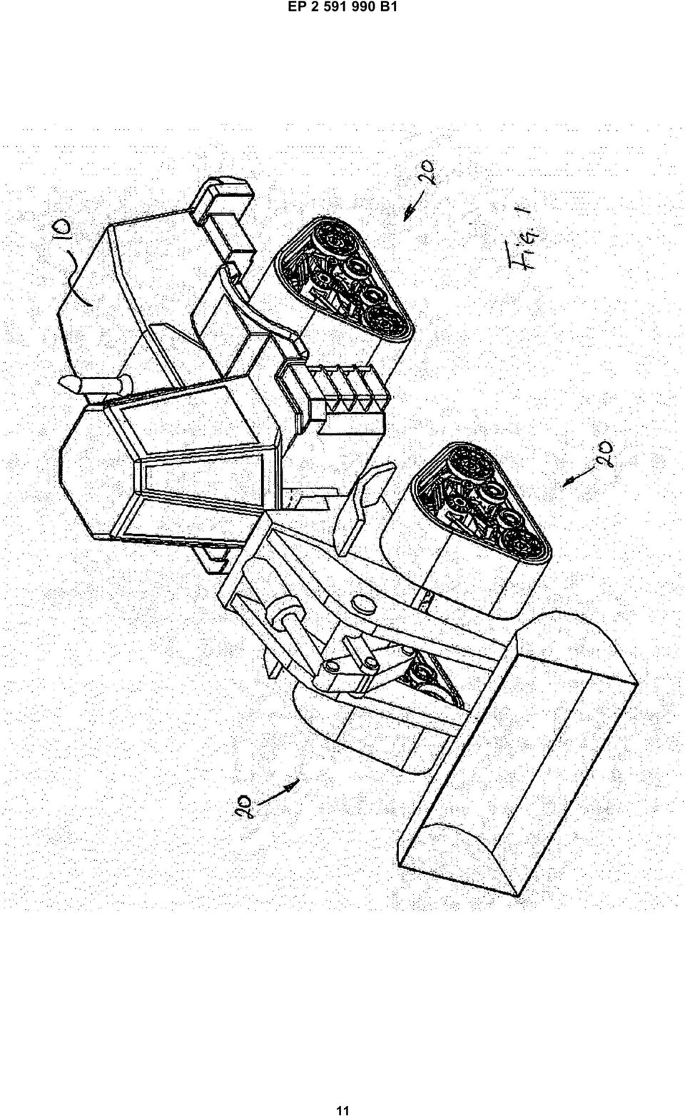
3 3 EP B1 4 [0014] In typical though non-limitative embodiments of a track system in accordance with the principles of the present invention, the rotation axes of the pivoting points of the tandem frames which respectively support the front and rear idler wheels are respectively located longitudinally in front of and behind the rotation axis of the drive wheel. [0015] In some non-limitative embodiments of a track system in accordance with the principles of the present invention, at least some of the road wheels are pivotally mounted to at least one tandem sub-frame, the at least one tandem sub-frame being pivotally mounted to one of the tandem frames. [0016] A track system in accordance with the principles of the present invention generally improves the load distributions between the idler wheels and the road wheels, and/or generally decreases the tendency of the pivoting point located behind the rotation axis of the drive wheel to move upwardly when the vehicle moves forwardly, and vice-versa, and/or generally reduces the lag time when the vehicle moving in a forward direction switches to move in a rearward direction, and vice-versa. [0017] Other and further aspects and advantages of the present invention will be obvious upon an understanding of the illustrative embodiments about to be described or will be indicated in the appended claims, and various advantages not referred to herein will occur to one skilled in the art upon employment of the invention in practice. The features of the present invention which are believed to be novel are set forth with particularity in the appended claims. Brief Description of the Drawings [0018] The above and other aspects, features and advantages of the invention will become more readily apparent from the following description, reference being made to the accompanying drawings in which: Figure 1 is a perspective view of a vehicle having mounted thereto four track systems in accordance with the principles to the present invention. Figure 2 is a perspective view of one of the track system of Fig. 1. Figure 3A is a side view of the track system of Fig. 2. Figure 3B is a side view of the track system of Fig. 2. Figure 4 is an exploded perspective view of the track system of Fig. 2, without the endless traction band. Figure 5 is a perspective view of another embodiment of a track system in accordance with the principles to the present invention, without the endless traction band. Figure 6 is a side view of the track system of Fig. 5. Figure 7 is a perspective view of a variant of the track system of Fig. 2, viewed from the inboard side. Figure 8 is a perspective view of another embodiment of a track system in accordance with the principles to the present invention, without the endless traction band. Figure 9 is a side view of the track system of Fig. 8. Detailed Description of the Preferred Embodiment [0019] A novel track system with overlapping wheel tandem frames will be described hereinafter. Although the invention is described in terms of specific illustrative embodiments, it is to be understood that the embodiments described herein are by way of example only and that the scope of the invention is not intended to be limited thereby. [0020] Referring first to Fig. 1, four track systems 20 made in accordance to the principles of the present invention are shown mounted to a vehicle. In Fig. 1, the vehicle is a front-loader typically used in construction. Notably, in Fig. 1, the track systems 20 are used to replace the wheels which are typically used on such vehicle. [0021] In Fig. 1, all four track systems 20 are identical though the left and right track systems 20 are mirror image of each other. Still, the front and rear track systems 20 could be different depending, among other things, on the configuration of the vehicle. For instance, some farming vehicles (e.g. tractors) sometimes use smaller front track systems and larger rear track systems. [0022] Referring now to Figs. 2 and 3A, one of the four track systems 20 is shown in greater details. [0023] In the present embodiment, the track system 20 comprises a drive wheel 22 configured to be mounted to the axle (not shown) of the vehicle. The drive wheel 22 defines a rotation axis 23 about which it rotates. The drive wheel 22 comprises, along its periphery 24, a plurality of evenly disposed sprocket teeth 26 configured to engage drive lugs (not shown) located on the inner surface 30 of the traction band 28. In the present embodiment, the drive wheel 22 is a sprocket wheel. [0024] The track system 20 also comprises a frame assembly 34 pivotally mounted to the drive wheel 22. Understandably, though the frame assembly 34 can pivot with respect to the drive wheel 22, the frame assembly 34 does not rotate with the drive wheel 22 as the frame assembly 34 is not drivingly engaged to the drive wheel 22. Though in the present embodiment, the frame assembly 34 is pivotally mounted to the drive wheel 22, in other embodiments, such as the one shown in Fig. 7, the frame assembly 34 could be configured to be mounted directly to the vehicle, typically to its frame. In such embodiments, the frame assembly 34 would typically comprise an attachment frame or assembly 90 configured to secure the frame assembly 34 to the vehicle. [0025] In the present embodiment, the frame assembly 34 pivotally supports two tandem frames 36 and 38. The front tandem frame 36 is pivotally mounted to the frame assembly 34 at front pivoting point 40 while the rear tandem frame 38 is pivotally mounted at rear pivoting point 42. [0026] The front pivoting point 40 defines a rotation 3
![[0015] In some non-limitative embodiments of a track system in accordance with the principles of the present invention, at least some of the road wheels are pivotally mounted to at least one tandem](/docs-images/47/20297989/images/page_3.jpg "sub-frame, the at least one tandem sub-frame being pivotally mounted to one of the tandem frames.")
4 5 EP B axis 41 while the rear pivoting point 42 defines a rotation axis 43. As best shown in Fig. 3A, in the present embodiment, the rotation axis 41 is located longitudinally in front of the drive wheel rotation axis 23 while the rotation axis 43 is located longitudinally behind the drive wheel rotation axis 23. [0027] In the present embodiment, the longitudinal distance between the rotation axis 41 and the drive wheel rotation axis 23 is substantially equal to the longitudinal distance between the rotation axis 43 and the drive wheel rotation axis 23. In other embodiments, these two distances could be different. [0028] Referring back to Figs. 2 and 3A, in the present embodiment, the front tandem frame 36 pivotally supports front idler wheels 44 and rear road wheels 46. In a substantially symmetrical fashion, the rear tandem frame 38 pivotally supports rear idler wheels 48 and front road wheels 50. [0029] The track system 20 also comprises the traction band 28, already introduced above, which is disposed about the drive wheel 22, the idler wheels 44 and 48 and the road wheels 46 and 50. The traction band 28 is typically made from reinforced elastomeric material and comprises an inner wheel-engaging surface 30 and an outer ground-engaging surface 32. [0030] Though not shown in the figures, the inner surface 30 of the traction band 28 typically comprises one or more rows of longitudinally aligned drive lugs and/or one or more rows of longitudinally aligned guide lugs (collectively referred to as "inner lugs"). The drive lugs are configured to be drivingly engaged by the sprocket teeth 26 of the drive wheel 22. [0031] In other embodiments, the inner surface 30 of the traction band 28 could only comprises guide lugs, and thus be devoid of drive lugs, such as to be frictionally engaged by the drive wheel 22 instead of being positively engaged thereby. [0032] Though not shown in the figures, the outer surface 32 of the traction band 28 typically comprises traction lugs configured to engage the terrain over which the track system 20 is operated. [0033] Referring now more particularly to Fig. 3A, the front pivoting point 40 allows the front tandem frame 36 to pivot thereabout, allowing the front idler wheels 44 and the rear road wheels 46 to move substantially vertically in opposite directions (e.g. upwardly and downwardly). Similarly, the rear pivoting point 42 allows the rear tandem frame 38 to pivot thereabout, allowing the rear idler wheels 48 and the front road wheels 50 to move substantially vertically in opposite directions (e.g. upwardly and downwardly). The ability of the idler wheels 44 and 48 and of the road wheels 46 and 50 to move substantially vertically as the tandem frames 36 and 38 pivot allows the lower run of the traction band 28, i.e. the portion of the traction band 28 which generally engages the ground, to substantially follow the irregularities of the terrain over which the track system 20 is operated. [0034] Still referring to Fig. 3A, in the present embodiment, the diameter of the idler wheels 44 and 48 is larger than the diameter of the road wheels 46 and 50. Having larger idler wheels 44 and 48 generally allows the track system 20 to more easily overcome obstacles and also to overcome larger obstacles. Larger idler wheels also generally reduce rolling resistance as it is easier to bend an elastomeric traction band around larger idler wheels than around smaller idler wheels. [0035] In addition, in the present embodiment, the longitudinal distance between the rotation axis 45 of the front idler wheels 44 and the rotation axis 41 of the front pivoting point 40 is smaller than the longitudinal distance between the rotation axis 47 of the rear road wheels 46 and the rotation axis 41 of the front pivoting point 40. Similarly, the longitudinal distance between the rotation axis 49 of the rear idler wheels 48 and the rotation axis 43 of the rear pivoting point 42 is smaller than the longitudinal distance between the rotation axis 51 of the front road wheels 50 and the rotation axis 43 of the rear pivoting point 42. [0036] As already mentioned above, the diameter of the idler wheels 44 and 48 is larger than the diameter of the road wheels 46 and 50. The present combination of the different longitudinal distances between the rotation axes and of the different wheel diameters generally allows a more balance load distribution between the larger idler wheels 44 and 48 and the smaller road wheels 46 and 50. Indeed, due to their smaller diameter, the smaller road wheels 46 and 50 have a load bearing capacity which is generally inferior to the load bearing capacity of the larger diameter idler wheels 44 and 48. Hence, to prevent the road wheels 46 and 50 from sinking excessively into the inner surface 30 of the elastomeric traction band 28, it is preferable to more evenly balance the load transmitted to and/or supported by the idler wheels 44 and 48 and by the road wheels 46 and 50 during operation of the track system 20. [0037] Typically, the load bearing capacity of a wheel will be generally proportional to its diameter. Hence, a wheel with a diameter twice as large as the diameter of another wheel would be able to support approximately twice the load. [0038] Thus, to generally evenly balance the load distribution between the idler wheels 44 and 48 and the road wheels 46 and 50, the ratio of the longitudinal distance between the rotation axis of the road wheels and the rotation axis of the tandem frame, to the longitudinal distance between the rotation axis of the idler wheels and the rotation axis of the tandem frame should be approximately equal to the ratio of the diameter of the idler wheels to the diameter of the road wheels. [0039] Understandably, other parameters (e.g. wheel width) could affect the relation between the longitudinal distances and the wheel diameters. In addition, one could choose particular distances and/or wheel diameters such as to change the load distribution. [0040] Referring now to Fig. 3B, when the track system 20 is operated such as to move in a forward direction, 4

5 7 EP B1 8 indicated by arrow F, the drive wheel 22 will rotate in a counterclockwise direction as indicated by arrow S. The rotation of the drive wheel 22 will pull on the portion of the traction band 28 located behind the drive wheel 22. This pulling, indicated by arrow T, will impart an upward motion to the rear idler wheels 48 as indicated by arrow RI. Because of the pivotal connection of the rear tandem frame 38 to the frame assembly 34, the upward motion of the rear idler wheels 48 will cause an opposite downward motion of the front road wheels 50 as indicated by arrow FR. [0041] However, as the longitudinal distance between the rotation axis 51 of the front road wheels 50 and the rotation axis 43 of the rear pivoting point 42 is larger than the longitudinal distance between the rotation axis 49 of the rear idler wheels 48 and the rotation axis 43 of the rear pivoting point 42, the downward motion of the front road wheels 50 will be countered, thereby limiting the upward motion of the rear idler wheels 48 and thus limiting the overall pivotal movement of the rear tandem frame 38. Indeed, the longer longitudinal distance between the rotation axis 51 of the front road wheels 50 and the rotation axis 43 of the rear pivoting point 42 creates a longer lever arm which can more easily counter the downward motion. [0042] Furthermore, if the track system 20 then switches to be operated such as to move in a rearward direction, the drive wheel 22 will then rotate in a clockwise direction and the situation of Fig. 3B will be essentially reversed. However, as the pivotal motion of the rear tandem frame 38 was previously limited, the time required to pivot the rear tandem frame 38 back to its normal position will be reduced, thereby reducing the lag time when the track system 20 switches from moving in a forward direction to moving in a rearward direction, and vice-versa. [0043] Understandably, frequent direction switching of the track system 20 can occur when the track system 20 is mounted to a vehicle, such as the front-loader shown in Fig. 1, which frequently switches direction during, for example, the handling of material. [0044] Hence, limiting the rotation of the rear tandem frame 38 with respect to the pivoting point 42 is beneficial as it generally reduces lag time during direction switching and as it generally provides a more stable operation of the track system 20, and thus a more stable operation of the vehicle. Understandably, when the vehicle is operated in reverse, the same principles apply to the front tandem frame 36 and its associated front idler wheels 44 and rear road wheels 46. [0045] In the present embodiment, the rotation axis 51 of the front road wheels 50 is located longitudinally in front of the rotation axis 23 of the drive wheel 22. Symmetrically, the rotation axis 47 of the rear road wheels 46 is located longitudinally behind the rotation axis 23 of the drive wheel 22. In addition, in the present embodiment, the center of gravity of the traction system 20 is substantially vertically aligned with the rotation axis 23 of the drive wheel 22. Understandably, the relative position of the rotation axes of the idler wheels, of the road wheels and of the pivoting points with respect to the rotation axis 23 of the drive wheel 22 can further improve the load distribution and the load transfer between the idler wheels and road wheels during operation of the track system 20. [0046] Referring now to Fig. 4, an exploded view of the track system 20, without the traction band 28 is shown. Notably, in the present embodiment, the frame assembly 34 comprises frame members 52, 54 and 56 between which are mounted blockers or limiters 53 and 55. While the frame member 52 is located on the outer or outboard side of the drive wheel 22, the frame members 54 and 56, are located on the inner or inboard side of the drive wheel 22. Understandably, the frame assembly 34 normally behaves as a unitary structure. For their part, the limiters 53 and 55 limit the amplitude of the pivotal movements of the tandem frames 36 and 38 with respect to the frame assembly 34. [0047] Referring now to Figs. 5 and 6, another embodiment of a track system 120 made in accordance with the principles of the present invention is shown. [0048] The track system 120 is broadly similar to track system 20 and therefore generally comprises a drive wheel 122, a frame assembly 134 pivotally mounted to the drive wheel 122, a front tandem frame 136 pivotally mounted to the frame assembly 134, a rear tandem frame 138 pivotally mounted to the frame assembly 134. [0049] However, though the front tandem frame 136 is similar to the front tandem frame 36 in that it supports the front idler wheels 144 and the rear road wheels 146, the rear tandem frame 138 differs from the rear tandem frame 38 in that it further pivotally supports a tandem sub-frame 160 where the rear tandem frame 138 pivotally supports the front road wheels 150. [0050] As best shown in Fig. 6, the tandem sub-frame 160 pivotally supports two sets of front road wheels 150, front road wheels 150A and front road wheels 150B. In other embodiments, there could be more than two sets of front road wheels 150. [0051] The additional set or sets of road wheels can be used to support larger loads (e.g. heavier vehicles) and/or to provide a smoother ride. The additional set or sets of road wheels can also be beneficial when a longer track system is needed (e.g. for improved stability). [0052] Understandably, depending on the exact configuration of the track system 120, the rear road wheels 146 could also be replaced by two or more sets of road wheels 146A and 146B mounted to a rear tandem subframe (not shown). [0053] Referring to Figs. 8 and 9, another embodiment of a track system 220 made in accordance with the principles of the present invention is shown. [0054] The track system 220 differs from track systems 20 and 120 in that the front and rear tandem frames 236 and 238 are not directly overlapping. However, track system 220 comprises at least one additional intermediate tandem frame 270, pivotally mounted to the support 5

6 9 EP B1 frame assembly 234 at 272, which overlaps both the front and rear tandem frames 236 and 238. [0055] Having one or more overlapping intermediate tandem frames, such as intermediate tandem frame 270, may be beneficial when, for example, longer track systems are required. [0056] Understandably, as shown in track system 220, when more than two tandem frames are present, the front and rear tandem frames may not directly overlap. However, in accordance with the principles of the present invention and as shown in track system 220, when more than two tandem frames are present, adjacent tandem frames should generally be overlapping. [0057] Still referring to Figs. 8 and 9, in this embodiment, the intermediate tandem frame 270 further supports a tandem sub-frame 280, similar to the tandem subframe 160 of the embodiment of Figs. 5 and 6. The tandem sub-frame 280 pivotally supports two sets of road wheels 282, road wheels 282A and 282B. [0058] Understandably, depending on the exact configuration of the track system 220, the front, rear and intermediate tandem frames 236, 238 and 270 could all pivotally support tandem sub-frames if appropriate. [0059] Understandably, the front and rear qualifiers used hereinabove are relative to the typically normal direction of movement of the track systems 20, 120 and 220 and have been use for ease of reference. However, the front and rear qualifiers should not be construed limitatively. [0060] While illustrative and presently preferred embodiments of the invention have been described in detail hereinabove, it is to be understood that the inventive concepts may be otherwise variously embodied and employed and that the appended claims are intended to be construed to include such variations except insofar as limited by the prior art. Claims 1. A track system (20, 120, 220) for a vehicle (), the track system (20, 120, 220) comprising: idler wheel (48, 148) and at least one second road wheel (50, 150); d) a traction band (28) disposed about the drive wheel (22, 122), the at least one first idler wheel (44, 144), the at least one second idler wheel (48, 148), the at least one first road wheel (46, 146), and the at least one second road wheel (50, 150); characterized in that adjacent tandem frames (36, 38, 136, 138, 236, 238, 270) are overlapping whereby the at least one first road wheel (46, 146) is located longitudinally between the wheels pivotally supported by the tandem frame (38, 138, 238, 270) adjacent to the first tandem frame (36, 136, 236), and whereby said at least one second road wheel (50, 150) is located longitudinally between the wheels pivotally supported by the tandem frame (36, 136, 236, 270) adjacent to the second tandem frame (38, 138, 238). 2. A track system as claimed in claim 1, wherein the tandem frame rotation axes (41, 43) are longitudinally spaced apart. 3. A track system as claimed in claim 2, wherein the drive wheel rotation axis (23) is located longitudinally between the first tandem frame rotation axis (41) and the second tandem frame rotation axis (43). 4. A track system as claimed in claim 1, wherein the at least one first idler wheel (44, 144) has a first idler wheel rotation axis (45), and wherein the at least one first road wheel (46, 146) has a first road wheel rotation axis (47). 5. A track system as claimed in claim 4, wherein a longitudinal distance between the first idler wheel rotation axis (45) and the first tandem frame rotation axis (41) is smaller than a longitudinal distance between the first tandem frame rotation axis (41) and the first road wheel rotation axis (47). a) a drive wheel (22, 122) configured to be mounted to the vehicle (), the drive wheel (22, 122) having a drive wheel rotation axis (23); b) a support frame (34, 134, 234); c) a plurality of tandem frames (36, 38, 136, 138, 236, 238, 270) pivotally mounted to the support frame (34, 134, 234), each of the tandem frames (36, 38, 136, 138, 236, 238, 270) having a tandem frame rotation axis (41, 43), the tandem frames (36, 38, 136, 138, 236, 238, 270) comprising at least a first tandem frame (36, 136, 236) pivotally supporting at least one first idler wheel (44, 144) and at least one first road wheel (46, 146), and a second tandem frame (38, 138, 238) pivotally supporting at least one second A track system as claimed in claim 5, wherein the at least one first idler wheel (44, 144) has a first idler wheel diameter, and wherein the at least one first road wheel (46, 146) has a first road wheel diameter, the first idler wheel diameter being larger than the first road wheel diameter. 7. A track system as claimed in any of claims 1 to 6, wherein the at least one second idler wheel (48, 148) has a second idler wheel rotation axis (49), and wherein the at least one second road wheel (50, 150) has a second road wheel rotation axis (51). 8. A track system as claimed in claim 7, wherein a longitudinal distance between the second idler wheel 6
![[0056] Understandably, as shown in track system 220, when more than two tandem frames are present, the front and rear tandem frames may not directly overlap.](/docs-images/47/20297989/images/page_6.jpg "However, in accordance with the principles of the present invention and as shown in track system 220, when more than two tandem frames are present, adjacent tandem frames should generally be")
7 11 EP B1 12 rotation axis (49) and the second tandem frame rotation axis (43) is smaller than a longitudinal distance between the second tandem frame rotation axis (43) and the second road wheel rotation axis (51). 9. A track system as claimed in claim 8, wherein the at least one second idler wheel (48) has a second idler wheel diameter, and wherein the at least one second road wheel (50) has a second road wheel diameter, the second idler wheel diameter being larger than the second road wheel diameter.. A track system as claimed in any of claims 1 to 9, wherein the tandem frames (36, 38, 136, 138, 236, 238, 270) comprise at least a third tandem frame (270) pivotally supporting at least one third road wheel and at least one fourth road wheel. 11. A track system as claimed in claim, wherein the third tandem frame rotation axis is located longitudinally between the first tandem frame rotation axis (41) and the second tandem frame rotation axis (43). 12. A track system as claimed in any of claims 1 to 11, wherein the at least one first idler wheel (44, 144) comprises a plurality of first idler wheels (44, 144), wherein the at least one first road wheel (46, 146) comprises a plurality of first road wheels (46, 146), wherein the at least one second idler wheel (48, 148) comprises a plurality of second idler wheels (48, 148), and wherein the at least one second road wheel (50, 150) comprises a plurality of second road wheels (50, 150). 13. A track system as claimed in any of claims 1 to 12, wherein at least one of the tandem frames (36, 38, 136, 138, 236, 238, 270) comprises at least one tandem sub-frame (160, 280) pivotally mounted to the at least one of the tandem frames (36, 38, 136, 138, 236, 238, 270), the at least one tandem sub-frame (160, 280) pivotally supporting at least two road wheels (150, 282). 14. A track system as claimed in any of claims 1to 13, wherein the support frame (34, 134, 234) is pivotally mounted to the drive wheel (22, 122). 15. A track system as claimed in any of claims 1to 13, wherein the support frame (34, 134, 234) is configured to be mounted to the vehicle (). 16. A track system as claimed in any of claims 1 to 15, wherein the first tandem frame (36, 136) is the front tandem frame (36, 136), wherein the second tandem frame (38, 138) is the rear tandem frame (38, 138), wherein the at least one first idler wheel (44, 144) is the at least one front idler wheel (44, 144), and wherein the at least one second idler wheel (48, 148) is the at least one rear idler wheel (48, 148). 17. A vehicle () having mounted thereto at least one track system (20, 120, 220) as claimed in any of claims 1 to 18. Patentansprüche 1. Raupenkettensystem (20, 120, 220) für ein Fahrzeug (), wobei das Raupenkettensystem (20, 120, 220) umfasst: a) ein Antriebsrad (22, 122), das so gestaltet ist, um an dem Fahrzeug () montiert zu werden, wobei das Antriebsrad (22, 122) eine Antriebsradrotationsachse (23) aufweist; b) einen Tragrahmen (34, 134, 234); c) eine Vielzahl von Tandemrahmen (36, 38, 136, 138, 236, 238, 270), die an dem Tragrahmen (34, 134, 234) drehgelenkig angeordnet sind, jeder der Tandemrahmen (36, 38, 136, 138, 236, 238, 270) eine Tandemrahmenrotationsachse (41, 43) aufweist, die Tandemrahmen (36, 38, 136, 138, 236, 238, 270) zumindest einen ersten Tandemrahmen (36, 136, 236), der zumindest ein erstes Leitrad (44, 144) und zumindest ein erstes Laufrad (46, 146) drehgelenkig lagert, und einen zweiten Tandemrahmen (38, 138, 238), der zumindest ein zweites Leitrad (48, 148) und zumindest ein zweites Laufrad (50, 150) drehgelenkig lagert, umfassen; d) einen Treibriemen (28), der um das Antriebsrad (22, 122), das zumindest eine erste Leitrad (44, 144), das zumindest eine zweite Leitrad (48, 148), das zumindest eine erste Laufrad (46, 146) und das zumindest eine zweite Laufrad (50, 150) herum angeordnet ist; dadurch gekennzeichnet, dass angrenzende Tandemrahmen (36, 38, 136, 138, 236, 238, 270) sich überschneiden, wodurch das zumindest eine erste Laufrad (46, 146) in Längsrichtung zwischen den Rädern liegt, die durch den an den ersten Tandemrahmen (36, 136, 236) angrenzenden Tandemrahmen (38, 138, 238, 270) drehgelenkig gelagert sind, und wodurch das zumindest eine zweite Laufrad (50, 150) in Längsrichtung zwischen den Rädern liegt, die durch den an den zweiten Tandemrahmen (38, 138, 238) angrenzenden Tandemrahmen (36, 136, 236, 270) drehgelenkig gelagert sind. 2. Raupenkettensystem nach Anspruch 1, wobei die Tandemrahmenrotationsachsen (41, 43) in Längsrichtung voneinander beanstandet sind. 3. Raupenkettensystem nach Anspruch 2, wobei die Antriebsradrotationsachse (23) in Längsrichtung 7

8 13 EP B1 14 zwischen der ersten Tandemrahmenrotationsachse (41) und der zweiten Tandemrahmenrotationsachse (43) liegt. 4. Raupenkettensystem nach Anspruch 1, wobei das zumindest eine erste Leitrad (44, 144) eine erste Leitradrotationsachse (45) aufweist, und wobei das zumindest eine erste Laufrad (46, 146) eine erste Laufradrotationsachse (47) aufweist. 5. Raupenkettensystem nach Anspruch 4, wobei ein Längsabstand zwischen der ersten Leitradrotationsachse (45) und der ersten Tandemrahmenrotationsachse (41) kleiner als ein Längsabstand zwischen der ersten Tandemrahmenrotationsachse (41) und der ersten Laufradrotationsachse (47) ist. 6. Raupenkettensystem nach Anspruch 5, wobei das zumindest eine erste Leitrad (44, 144) einen ersten Leitraddurchmesser aufweist, und wobei das zumindest eine erste Laufrad (46, 146) einen ersten Laufraddurchmesser aufweist, wobei der erste Leitraddurchmesser größer ist als der erste Laufraddurchmesser. 7. Raupenkettensystem nach einem der Ansprüche 1 bis 6, wobei das zumindest eine zweite Leitrad (48, 148) eine zweite Leitradrotationsachse (49) aufweist, und wobei das zumindest eine zweite Laufrad (50, 150) eine zweite Laufradradrotationsachse (51) aufweist Raupenkettensystem nach Anspruch, wobei die dritte Tandemrahmenrotationsachse in Längsrichtung zwischen der ersten Tandemrahmenrotationsachse (41) und der zweiten Tandemrahmenrotationsachse (43) liegt. 12. Raupenkettensystem nach einem der Ansprüche 1 bis 11, wobei das zumindest eine erste Leitrad (44, 144) eine Vielzahl von ersten Leiträdern (44, 144) aufweist, wobei das zumindest eine erste Laufrad (46, 146) eine Vielzahl von ersten Laufrädern (46, 146) aufweist, wobei das zumindest eine zweite Leitrad (48, 148) eine Vielzahl von zweiten Leiträdern (48, 148) aufweist, und wobei das zumindest eine zweite Laufrad (50, 150) eine Vielzahl von zweiten Laufrädern (50, 150) aufweist. 13. Raupenkettensystem nach einem der Ansprüche 1 bis 12, wobei zumindest einer der Tandemrahmen (36, 38, 136, 138, 236, 238, 270) zumindest einen Tandemhilfsrahmen (160, 280) aufweist, der an dem zumindest einen der Tandemrahmen (36, 38, 136, 138, 236, 238, 270) drehgelenkig angeordnet ist, wobei der zumindest eine Tandemhilfsrahmen (160, 280) zumindest zwei Laufräder (150, 282) drehgelenkig lagert. 14. Raupenkettensystem nach einem der Ansprüche 1 bis 13, wobei der Tragrahmen (34, 134, 234) an dem Antriebsrad (22, 122) drehgelenkig angeordnet ist. 15. Raupenkettensystem nach einem der Ansprüche 1 bis 13, wobei der Tragrahmen (34, 134, 234) so gestaltet ist, um an dem Fahrzeug () angeordnet zu werden. 8. Raupenkettensystem nach Anspruch 7, wobei ein Längsabstand zwischen der zweiten Leitradrotationsachse (49) und der zweiten Tandemrahmenrotationsachse (43) kleiner ist als ein Längsabstand zwischen der zweiten Tandemrahmenrotationsachse (43) und der zweiten Laufradrotationsachse (51). 9. Raupenkettensystem nach Anspruch 8, wobei das zumindest eine zweite Leitrad (48) einen zweiten Leitraddurchmesser aufweist, und wobei das zumindest eine zweite Laufrad (50) einen zweiten Laufraddurchmesser aufweist, wobei der zweite Leitraddurchmesser größer ist als der zweite Laufraddurchmesser Raupenkettensystem nach einem der Ansprüche 1 bis 15, wobei der erste Tandemrahmen (36, 136) der vordere Tandemrahmen (36, 136) ist, wobei der zweite Tandemrahmen (38, 138) der hintere Tandemrahmen (38, 138) ist, wobei das zumindest eine erste Leitrad (44, 144) das zumindest eine vordere Leitrad (44, 144) ist, und wobei das zumindest eine zweite Leitrad (48, 148) das zumindest eine hintere Leitrad (48, 148) ist. 17. Fahrzeug () mit einem daran montierten, zumindest einen Raupenkettensystem (20, 120, 220) nach einem der Ansprüche 1 bis 18.. Raupenkettensystem nach einem der Ansprüche 1 bis 9, wobei die Tandemrahmen (36, 38, 136, 138, 236, 238, 270) zumindest einen dritten Tandemrahmen (270) aufweisen, der mindestens ein drittes Laufrad und mindestens ein viertes Laufrad drehgelenkig trägt Revendications 1. Dispositif de chenilles (20, 120, 220) pour un véhicule (), le dispositif de chenilles (20, 120, 220) comprenant : a) une roue motrice (22, 122) configurée de manière à être montée sur le véhicule (), la roue motrice (22, 122) présentant un axe de rotation de roue motrice (23) ; b) un cadre de support (34, 134, 234) ; 8
 und der ersten Tandemrahmenrotationsachse (41) kleiner als ein Längsabstand zwischen der")
9 15 EP B1 16 c) une pluralité de cadres en tandem (36, 38, 136, 138, 236, 238, 270) montés de façon pivotante sur le cadre de support (34, 134, 234), chacun des cadres en tandem (36, 38, 136, 138, 236, 238, 270) présentant un axe de rotation de cadre en tandem (41, 43), les cadres en tandem (36, 38, 136, 138, 236, 238, 270) comprenant au moins un premier cadre en tandem (36, 136, 236) qui supporte de façon pivotante au moins une première roue folle (44, 144) et au moins une première roue routière (46, 146), et un deuxième cadre en tandem (38, 138, 238) qui supporte de façon pivotante au moins une deuxième roue folle (48, 148) et au moins une deuxième roue routière (50, 150) ; d) une bande de traction (28) disposée autour de la roue motrice (22, 122), de ladite au moins une première roue folle (44, 144), de ladite au moins une deuxième roue folle (48, 148), de ladite au moins une première roue routière (46, 146) et de ladite au moins une deuxième roue routière (50, 150) ; caractérisé en ce que des cadres en tandem adjacents (36, 38, 136, 138, 236, 238, 270) se chevauchent, moyennant quoi ladite au moins une première roue routière (46, 146) est disposée de façon longitudinale entre les roues supportées de façon pivotante par le cadre en tandem (38, 138, 238, 270) adjacent au premier cadre en tandem (36, 136, 236), et moyennant quoi ladite au moins une deuxième roue routière (50, 150) est disposée de façon longitudinale entre les roues supportées de façon pivotante par le cadre en tandem (36, 136, 236, 270) adjacent au deuxième cadre en tandem (38, 138, 238). 2. Dispositif de chenilles selon la revendication 1, dans lequel les axes de rotation de cadre en tandem (41, 43) sont espacés l un de l autre de façon longitudinale. 3. Dispositif de chenilles selon la revendication 2, dans lequel l axe de rotation de roue motrice (23) est disposé de façon longitudinale entre le premier axe de rotation de cadre en tandem (41) et le deuxième axe de rotation de cadre en tandem (43). 4. Dispositif de chenilles selon la revendication 1, dans lequel ladite au moins une première roue folle (44, 144) présente un premier axe de rotation de roue folle (45), et dans lequel ladite au moins une première roue routière (46, 146) présente un premier axe de rotation de roue routière (47). 5. Dispositif de chenilles selon la revendication 4, dans lequel une distance longitudinale entre le premier axe de rotation de roue folle (45) et le premier axe de rotation de cadre en tandem (41) est plus courte qu une distance longitudinale entre le premier axe de rotation de cadre en tandem (41) et le premier axe de rotation de roue routière (47). 6. Dispositif de chenilles selon la revendication 5, dans lequel ladite au moins une première roue folle (44, 144) présente un premier diamètre de roue folle, et dans lequel ladite au moins une première roue routière (46, 146) présente un premier diamètre de roue routière, le premier diamètre de roue folle étant plus grand que le premier diamètre de roue routière. 7. Dispositif de chenilles selon l une quelconque des revendications 1 à 6, dans lequel ladite au moins une deuxième roue folle (48, 148) présente un deuxième axe de rotation de roue folle (49), et dans lequel ladite au moins une deuxième roue routière (50, 150) présente un deuxième axe de rotation de roue routière (51). 8. Dispositif de chenilles selon la revendication 7, dans lequel une distance longitudinale entre le deuxième axe de rotation de roue folle (49) et le deuxième axe de rotation de cadre en tandem (43) est plus courte qu une distance longitudinale entre le deuxième axe de rotation de cadre en tandem (43) et le deuxième axe de rotation de roue routière (51). 9. Dispositif de chenilles selon la revendication 8, dans lequel ladite au moins une deuxième roue folle (48) présente un deuxième diamètre de roue folle, et dans lequel ladite au moins une deuxième roue routière (50) présente un deuxième diamètre de roue routière, le deuxième diamètre de roue folle étant plus grand que le deuxième diamètre de roue routière.. Dispositif de chenilles selon l une quelconque des revendications 1 à 9, dans lequel les cadres en tandem (36, 38, 136, 138, 236, 238, 270) comprennent au moins un troisième cadre en tandem (270) qui supporte de façon pivotante au moins une troisième roue routière et au moins une quatrième roue routière. 11. Dispositif de chenilles selon la revendication, dans lequel le troisième axe de rotation de cadre en tandem est disposé de façon longitudinale entre le premier axe de rotation de cadre en tandem (41) et le deuxième axe de rotation de cadre en tandem (43). 12. Dispositif de chenilles selon l une quelconque des revendications 1 à 11, dans lequel ladite au moins une première roue folle (44, 144) comprend une pluralité de premières roues folles (44, 144), dans lequel ladite au moins une première roue routière (46, 146) comprend une pluralité de premières roues routières 9
 et au moins une deuxième roue routière (50, 150) ; d) une bande de traction (28) disposée autour de la roue motrice (22, 122), de ladite au moins")
10 17 EP B1 18 (46, 146), dans lequel ladite au moins une deuxième roue folle (48, 148) comprend une pluralité de deuxièmes roues folles (48, 148), et dans lequel ladite au moins une deuxième roue routière (50, 150) comprend une pluralité de deuxièmes roues routières (50, 150) Dispositif de chenilles selon l une quelconque des revendications 1 à 12, dans lequel au moins un des cadres en tandem (36, 38, 136, 138, 236, 238, 270) comprend au moins un sous-cadre en tandem (160, 280) qui est monté de façon pivotante sur ledit au moins un des cadres en tandem (36, 38, 136, 138, 236, 238, 270), ledit au moins un sous-cadre en tandem (160, 280) supportant de façon pivotante au moins deux roues routières (150, 282) Dispositif de chenilles selon l une quelconque des revendications 1 à 13, dans lequel le cadre de support (34, 134, 234) est monté de façon pivotante sur la roue motrice (22, 122) Dispositif de chenilles selon l une quelconque des revendications 1 à 13, dans lequel le cadre de support (34, 134, 234) est configuré de manière à être monté sur le véhicule () Dispositif de chenilles selon l une quelconque des revendications 1 à 15, dans lequel le premier cadre en tandem (36, 136) est le cadre en tandem avant (36, 136), dans lequel le deuxième cadre en tandem (38, 138) est le cadre en tandem arrière (38, 138), dans lequel ladite au moins une première roue folle (44, 144) est ladite au moins une roue folle avant (44, 144), et dans lequel ladite au moins une deuxième roue folle (48, 148) est ladite au moins une roue folle arrière (48, 148) Véhicule () sur lequel au moins un dispositif de chenilles (20, 120, 220) selon l une quelconque des revendications 1 à 16 est monté
 qui est monté de façon pivotante sur ledit au moins un des cadres en tandem (36, 38, 136, 138, 236, 238, 270), ledit au moins un sous-cadre en tandem (160, 280) supportant de façon")
11 11
12 12

13 13

14 14

15 15

16 16

17 17

18 18

19 19

20 20

21 REFERENCES CITED IN THE DESCRIPTION This list of references cited by the applicant is for the reader s convenience only. It does not form part of the European patent document. Even though great care has been taken in compiling the references, errors or omissions cannot be excluded and the EPO disclaims all liability in this regard. Patent documents cited in the description US A [0001] US A [0007] 21
(51) Int Cl.: B29C 41/20 (2006.01) F21S 4/00 (2006.01) H05K 3/28 (2006.01)
 Int Cl.: B29C 41/20 (2006.01) F21S 4/00 (2006.01) H05K 3/28 (2006.01)") (19) TEPZZ 68698B_T (11) EP 2 68 698 B1 (12) EUROPEAN PATENT SPECIFICATION (4) Date of publication and mention of the grant of the patent: 18.11.201 Bulletin 201/47 (21) Application number: 11808612.3
(19) TEPZZ 68698B_T (11) EP 2 68 698 B1 (12) EUROPEAN PATENT SPECIFICATION (4) Date of publication and mention of the grant of the patent: 18.11.201 Bulletin 201/47 (21) Application number: 11808612.3
*EP001173363B1* EP 1 173 363 B1 (19) (11) EP 1 173 363 B1 (12) EUROPEAN PATENT SPECIFICATION
 (11) EP 1 173 363 B1 (12) EUROPEAN PATENT SPECIFICATION") (19) Europäisches Patentamt European Patent Office Office européen des brevets *EP001173363B1* (11) EP 1 173 363 B1 (12) EUROPEAN PATENT SPECIFICATION (4) Date of publication and mention of the grant of
(19) Europäisches Patentamt European Patent Office Office européen des brevets *EP001173363B1* (11) EP 1 173 363 B1 (12) EUROPEAN PATENT SPECIFICATION (4) Date of publication and mention of the grant of
(51) Int Cl.: H05K 1/02 (2006.01)
 Int Cl.: H05K 1/02 (2006.01)") (19) (11) EP 1 229 767 B1 (12) EUROPEAN PATENT SPECIFICATION (4) Date of publication and mention of the grant of the patent: 20.01.2010 Bulletin 2010/03 (1) Int Cl.: H0K 1/02 (2006.01) (21) Application
(19) (11) EP 1 229 767 B1 (12) EUROPEAN PATENT SPECIFICATION (4) Date of publication and mention of the grant of the patent: 20.01.2010 Bulletin 2010/03 (1) Int Cl.: H0K 1/02 (2006.01) (21) Application
(51) Int Cl.: G05F 3/26 (2006.01) G05F 3/24 (2006.01)
 Int Cl.: G05F 3/26 (2006.01) G05F 3/24 (2006.01)") (19) Europäisches Patentamt European Patent Office Office européen des brevets (11) EP 1 280 033 B1 (12) EUROPEAN PATENT SPECIFICATION (4) Date of publication and mention of the grant of the patent: 31.0.2006
(19) Europäisches Patentamt European Patent Office Office européen des brevets (11) EP 1 280 033 B1 (12) EUROPEAN PATENT SPECIFICATION (4) Date of publication and mention of the grant of the patent: 31.0.2006
(51) Int Cl.: H04L 29/06 (2006.01) G06F 9/445 (2006.01) G06F 13/00 (2006.01)
 Int Cl.: H04L 29/06 (2006.01) G06F 9/445 (2006.01) G06F 13/00 (2006.01)") (19) TEPZZ_7486_6B_T (11) EP 1 748 616 B1 (12) EUROPEAN PATENT SPECIFICATION (4) Date of publication and mention of the grant of the patent: 03.09.2014 Bulletin 2014/36 (1) Int Cl.: H04L 29/06 (2006.01)
(19) TEPZZ_7486_6B_T (11) EP 1 748 616 B1 (12) EUROPEAN PATENT SPECIFICATION (4) Date of publication and mention of the grant of the patent: 03.09.2014 Bulletin 2014/36 (1) Int Cl.: H04L 29/06 (2006.01)
*EP001520563A1* EP 1 520 563 A1 (19) (11) EP 1 520 563 A1 (12) EUROPEAN PATENT APPLICATION. (43) Date of publication: 06.04.2005 Bulletin 2005/14
 (11) EP 1 520 563 A1 (12) EUROPEAN PATENT APPLICATION. (43) Date of publication: 06.04.2005 Bulletin 2005/14") (19) Europäisches Patentamt European Patent Office Office européen des brevets *EP001520563A1* (11) EP 1 520 563 A1 (12) EUROPEAN PATENT APPLICATION (43) Date of publication: 06.04.2005 Bulletin 2005/14
(19) Europäisches Patentamt European Patent Office Office européen des brevets *EP001520563A1* (11) EP 1 520 563 A1 (12) EUROPEAN PATENT APPLICATION (43) Date of publication: 06.04.2005 Bulletin 2005/14
TEPZZ 87_546A T EP 2 871 546 A2 (19) (11) EP 2 871 546 A2 (12) EUROPEAN PATENT APPLICATION. (51) Int Cl.: G05B 19/05 (2006.01)
 (11) EP 2 871 546 A2 (12) EUROPEAN PATENT APPLICATION. (51) Int Cl.: G05B 19/05 (2006.01)") (19) TEPZZ 87_46A T (11) EP 2 871 46 A2 (12) EUROPEAN PATENT APPLICATION (43) Date of publication: 13.0.1 Bulletin 1/ (1) Int Cl.: G0B 19/0 (06.01) (21) Application number: 14188238.1 (22) Date of filing:
(19) TEPZZ 87_46A T (11) EP 2 871 46 A2 (12) EUROPEAN PATENT APPLICATION (43) Date of publication: 13.0.1 Bulletin 1/ (1) Int Cl.: G0B 19/0 (06.01) (21) Application number: 14188238.1 (22) Date of filing:
(51) Int Cl.: H04M 3/50 (2006.01)
 Int Cl.: H04M 3/50 (2006.01)") (19) TEPZZ_Z48_64B_T (11) EP 1 048 164 B1 (12) EUROPEAN PATENT SPECIFICATION (4) Date of publication and mention of the grant of the patent: 07.01.1 Bulletin 1/02 (21) Application number: 9893133.0 (22)
(19) TEPZZ_Z48_64B_T (11) EP 1 048 164 B1 (12) EUROPEAN PATENT SPECIFICATION (4) Date of publication and mention of the grant of the patent: 07.01.1 Bulletin 1/02 (21) Application number: 9893133.0 (22)
(51) Int Cl.: G06F 13/38 (2006.01) G06F 1/16 (2006.01)
 Int Cl.: G06F 13/38 (2006.01) G06F 1/16 (2006.01)") (19) TEPZZ 9777B_T (11) EP 2 97 77 B1 (12) EUROPEAN PATENT SPECIFICATION (4) Date of publication and mention of the grant of the patent: 1.07.1 Bulletin 1/29 (1) Int Cl.: G06F 13/38 (06.01) G06F 1/16 (06.01)
(19) TEPZZ 9777B_T (11) EP 2 97 77 B1 (12) EUROPEAN PATENT SPECIFICATION (4) Date of publication and mention of the grant of the patent: 1.07.1 Bulletin 1/29 (1) Int Cl.: G06F 13/38 (06.01) G06F 1/16 (06.01)
TEPZZ 6_Z76 A_T EP 2 610 763 A1 (19) (11) EP 2 610 763 A1 (12) EUROPEAN PATENT APPLICATION. (51) Int Cl.:
 (11) EP 2 610 763 A1 (12) EUROPEAN PATENT APPLICATION. (51) Int Cl.:") (19) TEPZZ 6_Z76 A_T (11) EP 2 6 763 A1 (12) EUROPEAN PATENT APPLICATION (43) Date of publication: 03.07.2013 Bulletin 2013/27 (51) Int Cl.: G06F 17/30 (2006.01) (21) Application number: 12192220.7 (22)
(19) TEPZZ 6_Z76 A_T (11) EP 2 6 763 A1 (12) EUROPEAN PATENT APPLICATION (43) Date of publication: 03.07.2013 Bulletin 2013/27 (51) Int Cl.: G06F 17/30 (2006.01) (21) Application number: 12192220.7 (22)
TEPZZ 69 _ZA T EP 2 692 310 A2 (19) (11) EP 2 692 310 A2. (12) EUROPEAN PATENT APPLICATION published in accordance with Art.
 (11) EP 2 692 310 A2. (12) EUROPEAN PATENT APPLICATION published in accordance with Art.") (19) TEPZZ 69 _ZA T (11) EP 2 692 3 A2 (12) EUROPEAN PATENT APPLICATION published in accordance with Art. 13(4) EPC (43) Date of publication: 0.02.14 Bulletin 14/06 (21) Application number: 1276632.0 (22)
(19) TEPZZ 69 _ZA T (11) EP 2 692 3 A2 (12) EUROPEAN PATENT APPLICATION published in accordance with Art. 13(4) EPC (43) Date of publication: 0.02.14 Bulletin 14/06 (21) Application number: 1276632.0 (22)
TEPZZ_768 7_B_T EP 1 768 371 B1 (19) (11) EP 1 768 371 B1 (12) EUROPEAN PATENT SPECIFICATION. (51) Int Cl.: H04M 19/04 (2006.01)
 (11) EP 1 768 371 B1 (12) EUROPEAN PATENT SPECIFICATION. (51) Int Cl.: H04M 19/04 (2006.01)") (19) TEPZZ_768 7_B_T (11) EP 1 768 371 B1 (12) EUROPEAN PATENT SPECIFICATION (4) Date of publication and mention of the grant of the patent: 1.01.2014 Bulletin 2014/03 (1) Int Cl.: H04M 19/04 (2006.01)
(19) TEPZZ_768 7_B_T (11) EP 1 768 371 B1 (12) EUROPEAN PATENT SPECIFICATION (4) Date of publication and mention of the grant of the patent: 1.01.2014 Bulletin 2014/03 (1) Int Cl.: H04M 19/04 (2006.01)
EP 2 455 926 A1 (19) (11) EP 2 455 926 A1 (12) EUROPEAN PATENT APPLICATION. (43) Date of publication: 23.05.2012 Bulletin 2012/21
 (11) EP 2 455 926 A1 (12) EUROPEAN PATENT APPLICATION. (43) Date of publication: 23.05.2012 Bulletin 2012/21") (19) (12) EUROPEAN PATENT APPLICATION (11) EP 2 4 926 A1 (43) Date of publication: 23.0.2012 Bulletin 2012/21 (21) Application number: 11190024.7 (1) Int Cl.: G08B 2/14 (2006.01) G08B 2/00 (2006.01) G0B
(19) (12) EUROPEAN PATENT APPLICATION (11) EP 2 4 926 A1 (43) Date of publication: 23.0.2012 Bulletin 2012/21 (21) Application number: 11190024.7 (1) Int Cl.: G08B 2/14 (2006.01) G08B 2/00 (2006.01) G0B
TEPZZ 9 Z5A_T EP 2 922 305 A1 (19) (11) EP 2 922 305 A1. (12) EUROPEAN PATENT APPLICATION published in accordance with Art.
 (11) EP 2 922 305 A1. (12) EUROPEAN PATENT APPLICATION published in accordance with Art.") (19) TEPZZ 9 ZA_T (11) EP 2 922 A1 (12) EUROPEAN PATENT APPLICATION published in accordance with Art. 13(4) EPC (43) Date of publication: 23.09.1 Bulletin 1/39 (21) Application number: 1386446.2 (22) Date
(19) TEPZZ 9 ZA_T (11) EP 2 922 A1 (12) EUROPEAN PATENT APPLICATION published in accordance with Art. 13(4) EPC (43) Date of publication: 23.09.1 Bulletin 1/39 (21) Application number: 1386446.2 (22) Date
Title (fr) SOURCE IONIQUE INTERNE DOUBLE POUR PRODUCTION DE FAISCEAU DE PARTICULES AVEC UN CYCLOTRON
 SOURCE IONIQUE INTERNE DOUBLE POUR PRODUCTION DE FAISCEAU DE PARTICULES AVEC UN CYCLOTRON") Title (en) A TWIN INTERNAL ION SOURCE FOR PARTICLE BEAM PRODUCTION WITH A CYCLOTRON Title (de) DOPPELTE INTERNE IONENQUELLE FÜR PARTIKELSTRAHLHERSTELLUNG MIT EINEM ZYKLOTRON Title (fr) SOURCE IONIQUE INTERNE
Title (en) A TWIN INTERNAL ION SOURCE FOR PARTICLE BEAM PRODUCTION WITH A CYCLOTRON Title (de) DOPPELTE INTERNE IONENQUELLE FÜR PARTIKELSTRAHLHERSTELLUNG MIT EINEM ZYKLOTRON Title (fr) SOURCE IONIQUE INTERNE
(51) Int Cl.: G06F 9/455 (2006.01) G06F 9/50 (2006.01)
 Int Cl.: G06F 9/455 (2006.01) G06F 9/50 (2006.01)") (19) TEPZZ 6987 B_T (11) EP 2 698 711 B1 (12) EUROPEAN PATENT SPECIFICATION (4) Date of publication and mention of the grant of the patent: 0.08.1 Bulletin 1/32 (21) Application number: 118777.8 (22) Date
(19) TEPZZ 6987 B_T (11) EP 2 698 711 B1 (12) EUROPEAN PATENT SPECIFICATION (4) Date of publication and mention of the grant of the patent: 0.08.1 Bulletin 1/32 (21) Application number: 118777.8 (22) Date
(51) Int Cl.: B62M 7/12 (2006.01) B62M 23/02 (2006.01)
 Int Cl.: B62M 7/12 (2006.01) B62M 23/02 (2006.01)") (19) (11) EP 1 810 918 B1 (12) EUROPEAN PATENT SPECIFICATION (4) Date of publication and mention of the grant of the patent: 18.11.2009 Bulletin 2009/47 (1) Int Cl.: B62M 7/12 (2006.01) B62M 23/02 (2006.01)
(19) (11) EP 1 810 918 B1 (12) EUROPEAN PATENT SPECIFICATION (4) Date of publication and mention of the grant of the patent: 18.11.2009 Bulletin 2009/47 (1) Int Cl.: B62M 7/12 (2006.01) B62M 23/02 (2006.01)
(51) Int Cl.: G10L 15/26 (2006.01)
 Int Cl.: G10L 15/26 (2006.01)") (19) TEPZZ Z 8B_T (11) EP 2 023 338 B1 (12) EUROPEAN PATENT SPECIFICATION (4) Date of publication and mention of the grant of the patent: 28.0.14 Bulletin 14/22 (1) Int Cl.: GL /26 (06.01) (21) Application
(19) TEPZZ Z 8B_T (11) EP 2 023 338 B1 (12) EUROPEAN PATENT SPECIFICATION (4) Date of publication and mention of the grant of the patent: 28.0.14 Bulletin 14/22 (1) Int Cl.: GL /26 (06.01) (21) Application
TEPZZ 65Z79 A_T EP 2 650 793 A1 (19) (11) EP 2 650 793 A1. (12) EUROPEAN PATENT APPLICATION published in accordance with Art.
 (11) EP 2 650 793 A1. (12) EUROPEAN PATENT APPLICATION published in accordance with Art.") (19) TEPZZ 65Z79 A_T (11) EP 2 650 793 A1 (12) EUROPEAN PATENT APPLICATION published in accordance with Art. 153(4) EPC (43) Date of publication: 16.10.2013 Bulletin 2013/42 (21) Application number: 12818771.3
(19) TEPZZ 65Z79 A_T (11) EP 2 650 793 A1 (12) EUROPEAN PATENT APPLICATION published in accordance with Art. 153(4) EPC (43) Date of publication: 16.10.2013 Bulletin 2013/42 (21) Application number: 12818771.3
(51) Int Cl.: C08K 5/523 (2006.01) C08K 5/521 (2006.01) C08K 5/52 (2006.01) C08G 64/00 (2006.01)
 Int Cl.: C08K 5/523 (2006.01) C08K 5/521 (2006.01) C08K 5/52 (2006.01) C08G 64/00 (2006.01)") (19) Europäisches Patentamt European Patent Office Office européen des brevets (11) EP 0 78 966 B1 (12) EUROPEAN PATENT SPECIFICATION (4) Date of publication and mention of the grant of the patent: 01.03.06
(19) Europäisches Patentamt European Patent Office Office européen des brevets (11) EP 0 78 966 B1 (12) EUROPEAN PATENT SPECIFICATION (4) Date of publication and mention of the grant of the patent: 01.03.06
TEPZZ 84 587A_T EP 2 843 587 A1 (19) (11) EP 2 843 587 A1 (12) EUROPEAN PATENT APPLICATION. (51) Int Cl.: G06F 21/64 (2013.01)
 (11) EP 2 843 587 A1 (12) EUROPEAN PATENT APPLICATION. (51) Int Cl.: G06F 21/64 (2013.01)") (19) TEPZZ 84 87A_T (11) EP 2 843 87 A1 (12) EUROPEAN PATENT APPLICATION (43) Date of publication: 04.03.201 Bulletin 201/ (1) Int Cl.: G06F 21/64 (2013.01) (21) Application number: 13181902.1 (22) Date
(19) TEPZZ 84 87A_T (11) EP 2 843 87 A1 (12) EUROPEAN PATENT APPLICATION (43) Date of publication: 04.03.201 Bulletin 201/ (1) Int Cl.: G06F 21/64 (2013.01) (21) Application number: 13181902.1 (22) Date
TEPZZ 68575_A_T EP 2 685 751 A1 (19) (11) EP 2 685 751 A1. (12) EUROPEAN PATENT APPLICATION published in accordance with Art.
 (11) EP 2 685 751 A1. (12) EUROPEAN PATENT APPLICATION published in accordance with Art.") (19) TEPZZ 687_A_T (11) EP 2 68 71 A1 (12) EUROPEAN PATENT APPLICATION published in accordance with Art. 3(4) EPC (43) Date of publication:.01.14 Bulletin 14/03 (21) Application number: 1278849.6 (22)
(19) TEPZZ 687_A_T (11) EP 2 68 71 A1 (12) EUROPEAN PATENT APPLICATION published in accordance with Art. 3(4) EPC (43) Date of publication:.01.14 Bulletin 14/03 (21) Application number: 1278849.6 (22)
EP 2 354 708 A2 (19) (11) EP 2 354 708 A2 (12) EUROPEAN PATENT APPLICATION. (43) Date of publication: 10.08.2011 Bulletin 2011/32
 (11) EP 2 354 708 A2 (12) EUROPEAN PATENT APPLICATION. (43) Date of publication: 10.08.2011 Bulletin 2011/32") (19) (12) EUROPEAN PATENT APPLICATION (11) EP 2 354 708 A2 (43) Date of publication:.08.2011 Bulletin 2011/32 (51) Int Cl.: F24H 3/08 (2006.01) F24H 8/00 (2006.01) (21) Application number: 111536.8 (22)
(19) (12) EUROPEAN PATENT APPLICATION (11) EP 2 354 708 A2 (43) Date of publication:.08.2011 Bulletin 2011/32 (51) Int Cl.: F24H 3/08 (2006.01) F24H 8/00 (2006.01) (21) Application number: 111536.8 (22)
(51) Int Cl.: G06F 11/20 (2006.01)
 Int Cl.: G06F 11/20 (2006.01)") (19) TEPZZ 66_ B_T (11) EP 2 366 13 B1 (12) EUROPEAN PATENT SPECIFICATION (4) Date of publication and mention of the grant of the patent: 13.0.201 Bulletin 201/20 (21) Application number: 08878183.6 (22)
(19) TEPZZ 66_ B_T (11) EP 2 366 13 B1 (12) EUROPEAN PATENT SPECIFICATION (4) Date of publication and mention of the grant of the patent: 13.0.201 Bulletin 201/20 (21) Application number: 08878183.6 (22)
(51) Int Cl.: H04N 7/16 (2011.01)
 Int Cl.: H04N 7/16 (2011.01)") (19) TEPZZ_796 89B_T (11) EP 1 796 389 B1 (12) EUROPEAN PATENT SPECIFICATION (4) Date of publication and mention of the grant of the patent: 04.03.1 Bulletin 1/ (1) Int Cl.: H04N 7/16 (11.01) (21) Application
(19) TEPZZ_796 89B_T (11) EP 1 796 389 B1 (12) EUROPEAN PATENT SPECIFICATION (4) Date of publication and mention of the grant of the patent: 04.03.1 Bulletin 1/ (1) Int Cl.: H04N 7/16 (11.01) (21) Application
(51) Int Cl.: H04L 29/06 (2006.01)
 Int Cl.: H04L 29/06 (2006.01)") (19) Europäisches Patentamt European Patent Office Office européen des brevets (11) EP 1 146 711 B1 (12) EUROPEAN PATENT SPECIFICATION (4) Date of publication and mention of the grant of the patent: 13.09.06
(19) Europäisches Patentamt European Patent Office Office européen des brevets (11) EP 1 146 711 B1 (12) EUROPEAN PATENT SPECIFICATION (4) Date of publication and mention of the grant of the patent: 13.09.06
EP 2 492 881 A2 (19) (11) EP 2 492 881 A2 (12) EUROPEAN PATENT APPLICATION. (43) Date of publication: 29.08.2012 Bulletin 2012/35
 (11) EP 2 492 881 A2 (12) EUROPEAN PATENT APPLICATION. (43) Date of publication: 29.08.2012 Bulletin 2012/35") (19) (12) EUROPEAN PATENT APPLICATION (11) EP 2 492 881 A2 (43) Date of publication: 29.08.2012 Bulletin 2012/35 (51) Int Cl.: G08B 13/16 (2006.01) G08B 25/08 (2006.01) (21) Application number: 12386006.6
(19) (12) EUROPEAN PATENT APPLICATION (11) EP 2 492 881 A2 (43) Date of publication: 29.08.2012 Bulletin 2012/35 (51) Int Cl.: G08B 13/16 (2006.01) G08B 25/08 (2006.01) (21) Application number: 12386006.6
The Advantialer and Its Advantages
 (19) TEPZZ Z B_T (11) EP 2 0 113 B1 (12) EUROPEAN PATENT SPECIFICATION (4) Date of publication and mention of the grant of the patent: 16.09.1 Bulletin 1/38 (21) Application number: 07809477.8 (22) Date
(51) Int Cl.: H04W 4/14 (2009.01)
 Int Cl.: H04W 4/14 (2009.01)") (19) (12) EUROPEAN PATENT SPECIFICATION (11) EP 2 184 897 B1 (4) Date of publication and mention of the grant of the patent: 14.03.12 Bulletin 12/11 (21) Application number: 087774.3 (22) Date of filing:
(19) (12) EUROPEAN PATENT SPECIFICATION (11) EP 2 184 897 B1 (4) Date of publication and mention of the grant of the patent: 14.03.12 Bulletin 12/11 (21) Application number: 087774.3 (22) Date of filing:
TEPZZ 858 ZB_T EP 2 858 320 B1 (19) (11) EP 2 858 320 B1 (12) EUROPEAN PATENT SPECIFICATION
 (11) EP 2 858 320 B1 (12) EUROPEAN PATENT SPECIFICATION") (19) TEPZZ 88 ZB_T (11) EP 2 88 3 B1 (12) EUROPEAN PATENT SPECIFICATION (4) Date of publication and mention of the grant of the patent: 06.04.16 Bulletin 16/14 (21) Application number: 1287929.9 (22) Date
(19) TEPZZ 88 ZB_T (11) EP 2 88 3 B1 (12) EUROPEAN PATENT SPECIFICATION (4) Date of publication and mention of the grant of the patent: 06.04.16 Bulletin 16/14 (21) Application number: 1287929.9 (22) Date
(51) Int Cl.: B65H 9/16 (2006.01) B65H 5/02 (2006.01)
 Int Cl.: B65H 9/16 (2006.01) B65H 5/02 (2006.01)") (19) (11) EP 1 4 6 B1 (12) EUROPEAN PATENT SPECIFICATION (4) Date of publication and mention of the grant of the patent: 17.09.08 Bulletin 08/38 (1) Int Cl.: B6H 9/16 (06.01) B6H /02 (06.01) (21) Application
(19) (11) EP 1 4 6 B1 (12) EUROPEAN PATENT SPECIFICATION (4) Date of publication and mention of the grant of the patent: 17.09.08 Bulletin 08/38 (1) Int Cl.: B6H 9/16 (06.01) B6H /02 (06.01) (21) Application
TEPZZ 87657ZA_T EP 2 876 570 A1 (19) (11) EP 2 876 570 A1 (12) EUROPEAN PATENT APPLICATION
 (11) EP 2 876 570 A1 (12) EUROPEAN PATENT APPLICATION") (19) TEPZZ 8767ZA_T (11) EP 2 876 70 A1 (12) EUROPEAN PATENT APPLICATION (43) Date of publication: 27.0.201 Bulletin 201/22 (21) Application number: 14189809.8 (1) Int Cl.: G06F 21/34 (2013.01) G08B 13/196
(19) TEPZZ 8767ZA_T (11) EP 2 876 70 A1 (12) EUROPEAN PATENT APPLICATION (43) Date of publication: 27.0.201 Bulletin 201/22 (21) Application number: 14189809.8 (1) Int Cl.: G06F 21/34 (2013.01) G08B 13/196
(51) Int Cl.: G06F 1/00 (2006.01)
 Int Cl.: G06F 1/00 (2006.01)") (19) TEPZZ_4 Z4ZB_T (11) EP 1 433 040 B1 (12) EUROPEAN PATENT SPECIFICATION (4) Date of publication and mention of the grant of the patent: 11.11.201 Bulletin 201/46 (21) Application number: 0277267.9
(19) TEPZZ_4 Z4ZB_T (11) EP 1 433 040 B1 (12) EUROPEAN PATENT SPECIFICATION (4) Date of publication and mention of the grant of the patent: 11.11.201 Bulletin 201/46 (21) Application number: 0277267.9
TEPZZ 8898 7A_T EP 2 889 827 A1 (19) (11) EP 2 889 827 A1 (12) EUROPEAN PATENT APPLICATION. (51) Int Cl.: G06Q 40/04 (2012.01)
 (11) EP 2 889 827 A1 (12) EUROPEAN PATENT APPLICATION. (51) Int Cl.: G06Q 40/04 (2012.01)") (19) TEPZZ 8898 7A_T (11) EP 2 889 827 A1 (12) EUROPEAN PATENT APPLICATION (43) Date of publication: 01.07.201 Bulletin 201/27 (1) Int Cl.: G06Q 40/04 (2012.01) (21) Application number: 14199864.1 (22)
(19) TEPZZ 8898 7A_T (11) EP 2 889 827 A1 (12) EUROPEAN PATENT APPLICATION (43) Date of publication: 01.07.201 Bulletin 201/27 (1) Int Cl.: G06Q 40/04 (2012.01) (21) Application number: 14199864.1 (22)
TEPZZ 69 49A_T EP 2 693 349 A1 (19) (11) EP 2 693 349 A1 (12) EUROPEAN PATENT APPLICATION. (51) Int Cl.: G06F 17/30 (2006.01)
 (11) EP 2 693 349 A1 (12) EUROPEAN PATENT APPLICATION. (51) Int Cl.: G06F 17/30 (2006.01)") (19) TEPZZ 69 49A_T (11) EP 2 693 349 A1 (12) EUROPEAN PATENT APPLICATION (43) Date of publication: 0.02.2014 Bulletin 2014/06 (1) Int Cl.: G06F 17/30 (2006.01) (21) Application number: 13160696.4 (22)
(19) TEPZZ 69 49A_T (11) EP 2 693 349 A1 (12) EUROPEAN PATENT APPLICATION (43) Date of publication: 0.02.2014 Bulletin 2014/06 (1) Int Cl.: G06F 17/30 (2006.01) (21) Application number: 13160696.4 (22)
(51) Int Cl.: H04N 1/19 (2006.01) H04N 3/15 (2006.01) H04N 9/04 (2006.01)
 Int Cl.: H04N 1/19 (2006.01) H04N 3/15 (2006.01) H04N 9/04 (2006.01)") (19) (12) EUROPEAN PATENT SPECIFICATION (11) EP 1 417 829 B1 (45) Date of publication and mention of the grant of the patent: 08.04.2009 Bulletin 2009/15 (21) Application number: 02751534.5 (22) Date of
(19) (12) EUROPEAN PATENT SPECIFICATION (11) EP 1 417 829 B1 (45) Date of publication and mention of the grant of the patent: 08.04.2009 Bulletin 2009/15 (21) Application number: 02751534.5 (22) Date of
TEPZZ 46699B_T EP 2 346 699 B1 (19) (11) EP 2 346 699 B1 (12) EUROPEAN PATENT SPECIFICATION
 (11) EP 2 346 699 B1 (12) EUROPEAN PATENT SPECIFICATION") (19) TEPZZ 46699B_T (11) EP 2 346 699 B1 (12) EUROPEAN PATENT SPECIFICATION (4) Date of publication and mention of the grant of the patent: 29.01.14 Bulletin 14/0 (21) Application number: 098101.9 (22)
(19) TEPZZ 46699B_T (11) EP 2 346 699 B1 (12) EUROPEAN PATENT SPECIFICATION (4) Date of publication and mention of the grant of the patent: 29.01.14 Bulletin 14/0 (21) Application number: 098101.9 (22)
(51) Int Cl.: G06F 21/00 (2006.01) H04L 29/06 (2006.01)
 Int Cl.: G06F 21/00 (2006.01) H04L 29/06 (2006.01)") (19) TEPZZ_8Z_7 _B_T (11) EP 1 801 721 B1 (12) EUROPEAN PATENT SPECIFICATION (4) Date of publication and mention of the grant of the patent: 16.06. Bulletin /24 (1) Int Cl.: G06F 21/00 (06.01) H04L 29/06
(19) TEPZZ_8Z_7 _B_T (11) EP 1 801 721 B1 (12) EUROPEAN PATENT SPECIFICATION (4) Date of publication and mention of the grant of the patent: 16.06. Bulletin /24 (1) Int Cl.: G06F 21/00 (06.01) H04L 29/06
(51) Int Cl.: A61M 15/00 (2006.01) A61M 15/08 (2006.01)
 Int Cl.: A61M 15/00 (2006.01) A61M 15/08 (2006.01)") (19) (11) EP 1 39 28 B1 (12) EUROPEAN PATENT SPECIFICATION (4) Date of publication and mention of the grant of the patent: 16.07.08 Bulletin 08/29 (21) Application number: 0280770.1 (22) Date of filing:
(19) (11) EP 1 39 28 B1 (12) EUROPEAN PATENT SPECIFICATION (4) Date of publication and mention of the grant of the patent: 16.07.08 Bulletin 08/29 (21) Application number: 0280770.1 (22) Date of filing:
(51) Int Cl. 7 : G03G 15/00
 Int Cl. 7 : G03G 15/00") (19) Europäisches Patentamt European Patent Office Office européen des brevets *EP001179B1* (11) EP 1 17 9 B1 (12) EUROPEAN PATENT SPECIFICATION (4) Date of publication and mention of the grant of the
(19) Europäisches Patentamt European Patent Office Office européen des brevets *EP001179B1* (11) EP 1 17 9 B1 (12) EUROPEAN PATENT SPECIFICATION (4) Date of publication and mention of the grant of the
Our patent and trade mark attorneys are here to help you protect and profit from your ideas, making sure they re working every bit as hard as you do.
 Our patent and trade mark attorneys are here to help you protect and profit from your ideas, making sure they re working every bit as hard as you do. Our people work with everyone from multi-nationals
(51) Int Cl.: H01M 8/04 (2006.01)
 Int Cl.: H01M 8/04 (2006.01)") (19) (11) EP 1 791 20 B1 (12) EUROPEAN PATENT SPECIFICATION (4) Date of publication and mention of the grant of the patent: 12.09.2012 Bulletin 2012/37 (1) Int Cl.: H01M 8/04 (2006.01) (21) Application
(19) (11) EP 1 791 20 B1 (12) EUROPEAN PATENT SPECIFICATION (4) Date of publication and mention of the grant of the patent: 12.09.2012 Bulletin 2012/37 (1) Int Cl.: H01M 8/04 (2006.01) (21) Application
(51) Int Cl.: H04N 5/225 (2006.01)
 Int Cl.: H04N 5/225 (2006.01)") (19) TEPZZ_94 66_B_T (11) EP 1 942 661 B1 (12) EUROPEAN PATENT SPECIFICATION (4) Date of publication and mention of the grant of the patent: 17.09.2014 Bulletin 2014/38 (1) Int Cl.: H04N /22 (2006.01)
(19) TEPZZ_94 66_B_T (11) EP 1 942 661 B1 (12) EUROPEAN PATENT SPECIFICATION (4) Date of publication and mention of the grant of the patent: 17.09.2014 Bulletin 2014/38 (1) Int Cl.: H04N /22 (2006.01)
(51) Int Cl.: G06F 13/42 (2006.01)
 Int Cl.: G06F 13/42 (2006.01)") (19) TEPZZ 67487_B_T (11) EP 2 674 871 B1 (12) EUROPEAN PATENT SPECIFICATION (4) Date of publication and mention of the grant of the patent: 04.03.201 Bulletin 201/ (1) Int Cl.: G06F 13/42 (2006.01) (21)
(19) TEPZZ 67487_B_T (11) EP 2 674 871 B1 (12) EUROPEAN PATENT SPECIFICATION (4) Date of publication and mention of the grant of the patent: 04.03.201 Bulletin 201/ (1) Int Cl.: G06F 13/42 (2006.01) (21)
(51) Int Cl.: G04B 19/08 (2006.01)
 Int Cl.: G04B 19/08 (2006.01)") (19) (11) EP 1 988 432 B1 (12) EUROPEAN PATENT SPECIFICATION (4) Date of publication and mention of the grant of the patent: 0.10.2011 Bulletin 2011/40 (21) Application number: 0771278.9 (22) Date of filing:
(19) (11) EP 1 988 432 B1 (12) EUROPEAN PATENT SPECIFICATION (4) Date of publication and mention of the grant of the patent: 0.10.2011 Bulletin 2011/40 (21) Application number: 0771278.9 (22) Date of filing:
EP 2 365 669 A1 (19) (11) EP 2 365 669 A1 (12) EUROPEAN PATENT APPLICATION. (43) Date of publication: 14.09.2011 Bulletin 2011/37
 (11) EP 2 365 669 A1 (12) EUROPEAN PATENT APPLICATION. (43) Date of publication: 14.09.2011 Bulletin 2011/37") (19) (12) EUROPEAN PATENT APPLICATION (11) EP 2 36 669 A1 (43) Date of publication: 14.09.11 Bulletin 11/37 (1) Int Cl.: H04L 12/8 (06.01) (21) Application number: 00243.6 (22) Date of filing:.03. (84)
(19) (12) EUROPEAN PATENT APPLICATION (11) EP 2 36 669 A1 (43) Date of publication: 14.09.11 Bulletin 11/37 (1) Int Cl.: H04L 12/8 (06.01) (21) Application number: 00243.6 (22) Date of filing:.03. (84)
TEPZZ_9 6Z46B_T EP 1 926 046 B1 (19) (11) EP 1 926 046 B1 (12) EUROPEAN PATENT SPECIFICATION. (51) Int Cl.:
 (11) EP 1 926 046 B1 (12) EUROPEAN PATENT SPECIFICATION. (51) Int Cl.:") (19) TEPZZ_9 6Z46B_T (11) EP 1 926 046 B1 (12) EUROPEAN PATENT SPECIFICATION (4) Date of publication and mention of the grant of the patent: 21.08.13 Bulletin 13/34 (1) Int Cl.: G06F 19/00 (11.01) (21)
(19) TEPZZ_9 6Z46B_T (11) EP 1 926 046 B1 (12) EUROPEAN PATENT SPECIFICATION (4) Date of publication and mention of the grant of the patent: 21.08.13 Bulletin 13/34 (1) Int Cl.: G06F 19/00 (11.01) (21)
(51) Int Cl.: H04L 9/24 (2006.01) G06Q 10/00 (2012.01)
 Int Cl.: H04L 9/24 (2006.01) G06Q 10/00 (2012.01)") (19) TEPZZ_4Z 68ZB_T (11) EP 1 2 680 B1 (12) EUROPEAN PATENT SPECIFICATION (4) Date of publication and mention of the grant of the patent: 01.04.1 Bulletin 1/14 (21) Application number: 02741722.9 (22)
(19) TEPZZ_4Z 68ZB_T (11) EP 1 2 680 B1 (12) EUROPEAN PATENT SPECIFICATION (4) Date of publication and mention of the grant of the patent: 01.04.1 Bulletin 1/14 (21) Application number: 02741722.9 (22)
Invention of a Dental Appraisal
 à Europâisches Patentamt European Patent Office Office européen des brevets (J) Publication number: 0 042 2 6 7 B1 EUROPEAN PATENT SPECIFICATION ( ) Date of publication of patent spécification: 15.05.85
TEPZZ Z9Z75 B_T EP 2 090 752 B1 (19) (11) EP 2 090 752 B1 (12) EUROPEAN PATENT SPECIFICATION
 (11) EP 2 090 752 B1 (12) EUROPEAN PATENT SPECIFICATION") (19) TEPZZ Z9Z7 B_T (11) EP 2 090 72 B1 (12) EUROPEAN PATENT SPECIFICATION (4) Date of publication and mention of the grant of the patent: 1.01.14 Bulletin 14/03 (21) Application number: 0934.7 (1) Int
(19) TEPZZ Z9Z7 B_T (11) EP 2 090 72 B1 (12) EUROPEAN PATENT SPECIFICATION (4) Date of publication and mention of the grant of the patent: 1.01.14 Bulletin 14/03 (21) Application number: 0934.7 (1) Int
TEPZZ 8 8 A_T EP 2 811 282 A1 (19) (11) EP 2 811 282 A1 (12) EUROPEAN PATENT APPLICATION. (51) Int Cl.: G01N 3/04 (2006.01) G01N 3/08 (2006.
 (11) EP 2 811 282 A1 (12) EUROPEAN PATENT APPLICATION. (51) Int Cl.: G01N 3/04 (2006.01) G01N 3/08 (2006.") (19) TEPZZ 8 8 A_T (11) EP 2 811 282 A1 (12) EUROPEAN PATENT APPLICATION (43) Date of publication:.12.14 Bulletin 14/0 (1) Int Cl.: G01N 3/04 (06.01) G01N 3/08 (06.01) (21) Application number: 14170412.2
(19) TEPZZ 8 8 A_T (11) EP 2 811 282 A1 (12) EUROPEAN PATENT APPLICATION (43) Date of publication:.12.14 Bulletin 14/0 (1) Int Cl.: G01N 3/04 (06.01) G01N 3/08 (06.01) (21) Application number: 14170412.2
TEPZZ 9 _88_A_T EP 2 921 881 A1 (19) (11) EP 2 921 881 A1 (12) EUROPEAN PATENT APPLICATION
 (11) EP 2 921 881 A1 (12) EUROPEAN PATENT APPLICATION") (19) TEPZZ 9 _88_A_T (11) EP 2 921 881 A1 (12) EUROPEAN PATENT APPLICATION (43) Date of publication: 23.09.1 Bulletin 1/39 (21) Application number: 1416041.2 (1) Int Cl.: G01T 1/ (06.01) G03B 42/02 (06.01)
(19) TEPZZ 9 _88_A_T (11) EP 2 921 881 A1 (12) EUROPEAN PATENT APPLICATION (43) Date of publication: 23.09.1 Bulletin 1/39 (21) Application number: 1416041.2 (1) Int Cl.: G01T 1/ (06.01) G03B 42/02 (06.01)
(51) Int Cl.: G06F 1/00 (2006.01)
 Int Cl.: G06F 1/00 (2006.01)") (19) (11) EP 0 972 234 B1 (12) EUROPEAN PATENT SPECIFICATION (4) Date of publication and mention of the grant of the patent: 0.09.07 Bulletin 07/36 (21) Application number: 98913219.6 (22) Date of filing:
(19) (11) EP 0 972 234 B1 (12) EUROPEAN PATENT SPECIFICATION (4) Date of publication and mention of the grant of the patent: 0.09.07 Bulletin 07/36 (21) Application number: 98913219.6 (22) Date of filing:
(51) Int Cl.: H04L 12/56 (2006.01)
 Int Cl.: H04L 12/56 (2006.01)") (19) (11) EP 1 779 90 B1 (12) EUROPEAN PATENT SPECIFICATION (4) Date of publication and mention of the grant of the patent: 28.12.11 Bulletin 11/2 (21) Application number: 0783482.2 (22) Date of filing:
(19) (11) EP 1 779 90 B1 (12) EUROPEAN PATENT SPECIFICATION (4) Date of publication and mention of the grant of the patent: 28.12.11 Bulletin 11/2 (21) Application number: 0783482.2 (22) Date of filing:
TEPZZ_57 7_9B_T EP 1 573 719 B1 (19) (11) EP 1 573 719 B1 (12) EUROPEAN PATENT SPECIFICATION
 (11) EP 1 573 719 B1 (12) EUROPEAN PATENT SPECIFICATION") (19) TEPZZ_7 7_9B_T (11) EP 1 73 719 B1 (12) EUROPEAN PATENT SPECIFICATION (4) Date of publication and mention of the grant of the patent:.11.13 Bulletin 13/47 (21) Application number: 0277098.3 (22) Date
(19) TEPZZ_7 7_9B_T (11) EP 1 73 719 B1 (12) EUROPEAN PATENT SPECIFICATION (4) Date of publication and mention of the grant of the patent:.11.13 Bulletin 13/47 (21) Application number: 0277098.3 (22) Date
(51) Int Cl.: G10L 19/00 (2006.01) H04L 1/20 (2006.01)
 Int Cl.: G10L 19/00 (2006.01) H04L 1/20 (2006.01)") (19) Europäisches Patentamt European Patent Office Office européen des brevets (11) EP 1 317 72 B1 (12) EUROPEAN PATENT SPECIFICATION (4) Date of publication and mention of the grant of the patent:.08.06
(19) Europäisches Patentamt European Patent Office Office européen des brevets (11) EP 1 317 72 B1 (12) EUROPEAN PATENT SPECIFICATION (4) Date of publication and mention of the grant of the patent:.08.06
(51) Int Cl.: H04L 9/32 (2006.01) H04B 7/00 (2006.01) A61N 1/37 (2006.01)
 Int Cl.: H04L 9/32 (2006.01) H04B 7/00 (2006.01) A61N 1/37 (2006.01)") (19) TEPZZ_4977B_T (11) EP 1 49 77 B1 (12) EUROPEAN PATENT SPECIFICATION (4) Date of publication and mention of the grant of the patent:.12.14 Bulletin 14/0 (21) Application number: 03723989.4 (22) Date
(19) TEPZZ_4977B_T (11) EP 1 49 77 B1 (12) EUROPEAN PATENT SPECIFICATION (4) Date of publication and mention of the grant of the patent:.12.14 Bulletin 14/0 (21) Application number: 03723989.4 (22) Date
(51) Int Cl.: H04L 12/46 (2006.01) H04L 29/14 (2006.01) H04L 29/12 (2006.01)
 Int Cl.: H04L 12/46 (2006.01) H04L 29/14 (2006.01) H04L 29/12 (2006.01)") (19) (11) EP 1 342 344 B1 (12) EUROPEAN PATENT SPECIFICATION (4) Date of publication and mention of the grant of the patent: 03.06.09 Bulletin 09/23 (21) Application number: 019639.0 (22) Date of filing:.08.01
(19) (11) EP 1 342 344 B1 (12) EUROPEAN PATENT SPECIFICATION (4) Date of publication and mention of the grant of the patent: 03.06.09 Bulletin 09/23 (21) Application number: 019639.0 (22) Date of filing:.08.01
(51) Int Cl.: H04L 12/24 (2006.01)
 Int Cl.: H04L 12/24 (2006.01)") (19) (12) EUROPEAN PATENT SPECIFICATION (11) EP 1 487 11 B1 (4) Date of publication and mention of the grant of the patent: 01.07.09 Bulletin 09/27 (1) Int Cl.: H04L 12/24 (06.01) (21) Application number:
(19) (12) EUROPEAN PATENT SPECIFICATION (11) EP 1 487 11 B1 (4) Date of publication and mention of the grant of the patent: 01.07.09 Bulletin 09/27 (1) Int Cl.: H04L 12/24 (06.01) (21) Application number:
EUROPEAN PATENT APPLICATION. Hudson, NC 28638 (US) Chancery Lane London WC2A 1QU (GB)
 Chancery Lane London WC2A 1QU (GB)") (19) (12) Europaisches Patentamt European Patent Office Office europeen een des brevets EUROPEAN PATENT APPLICATION EP 0 889 344 A1 (43) Date of publication: (51) nt CI.6: G 02 B 6/44 07.01.1999 Bulletin
(19) (12) Europaisches Patentamt European Patent Office Office europeen een des brevets EUROPEAN PATENT APPLICATION EP 0 889 344 A1 (43) Date of publication: (51) nt CI.6: G 02 B 6/44 07.01.1999 Bulletin
(51) Int Cl.: H04L 12/00 (2006.01)
 Int Cl.: H04L 12/00 (2006.01)") (19) (11) EP 2 119 B1 (12) EUROPEAN PATENT SPECIFICATION (4) Date of publication and mention of the grant of the patent: 14.12.11 Bulletin 11/0 (21) Application number: 0789037.9 (22) Date of filing: 14.12.07
(19) (11) EP 2 119 B1 (12) EUROPEAN PATENT SPECIFICATION (4) Date of publication and mention of the grant of the patent: 14.12.11 Bulletin 11/0 (21) Application number: 0789037.9 (22) Date of filing: 14.12.07
(51) Int Cl.: H04L 29/06 (2006.01) H04M 15/00 (2006.01)
 Int Cl.: H04L 29/06 (2006.01) H04M 15/00 (2006.01)") (19) TEPZZ 7Z 74 B_T (11) EP 2 702 742 B1 (12) EUROPEAN PATENT SPECIFICATION (4) Date of publication and mention of the grant of the patent:.04. Bulletin /16 (21) Application number: 1171674.6 (22) Date
(19) TEPZZ 7Z 74 B_T (11) EP 2 702 742 B1 (12) EUROPEAN PATENT SPECIFICATION (4) Date of publication and mention of the grant of the patent:.04. Bulletin /16 (21) Application number: 1171674.6 (22) Date
(56) References cited:
 References cited:") (19) (12) EUROPEAN PATENT SPECIFICATION (11) EP 1 371 26 B1 (4) Date of publication and mention of the grant of the patent: 21.01.09 Bulletin 09/04 (21) Application number: 02711612.8 (22) Date of filing:
(19) (12) EUROPEAN PATENT SPECIFICATION (11) EP 1 371 26 B1 (4) Date of publication and mention of the grant of the patent: 21.01.09 Bulletin 09/04 (21) Application number: 02711612.8 (22) Date of filing:
(51) Int Cl.: H04B 3/23 (2006.01)
 Int Cl.: H04B 3/23 (2006.01)") (19) (11) EP 0 983 638 B1 (12) EUROPEAN PATENT SPECIFICATION (4) Date of publication and mention of the grant of the patent: 21.03.12 Bulletin 12/12 (21) Application number: 989232.7 (22) Date of filing:
(19) (11) EP 0 983 638 B1 (12) EUROPEAN PATENT SPECIFICATION (4) Date of publication and mention of the grant of the patent: 21.03.12 Bulletin 12/12 (21) Application number: 989232.7 (22) Date of filing:
(51) Int Cl.: H04L 9/32 (2006.01) G09C 1/00 (2006.01) G06F 21/33 (2013.01) H04L 29/06 (2006.01)
 Int Cl.: H04L 9/32 (2006.01) G09C 1/00 (2006.01) G06F 21/33 (2013.01) H04L 29/06 (2006.01)") (19) TEPZZ Z48B_T (11) EP 2 2 048 B1 (12) EUROPEAN PATENT SPECIFICATION (4) Date of publication and mention of the grant of the patent: 13.0. Bulletin / (21) Application number: 1179238.6 (22) Date of
(19) TEPZZ Z48B_T (11) EP 2 2 048 B1 (12) EUROPEAN PATENT SPECIFICATION (4) Date of publication and mention of the grant of the patent: 13.0. Bulletin / (21) Application number: 1179238.6 (22) Date of
TEPZZ 799965A_T EP 2 799 965 A1 (19) (11) EP 2 799 965 A1. (12) EUROPEAN PATENT APPLICATION published in accordance with Art.
 (11) EP 2 799 965 A1. (12) EUROPEAN PATENT APPLICATION published in accordance with Art.") (19) TEPZZ 79996A_T (11) EP 2 799 96 A1 (12) EUROPEAN PATENT APPLICATION published in accordance with Art. 13(4) EPC (43) Date of publication: 0.11.14 Bulletin 14/4 (21) Application number: 14727698.4
(19) TEPZZ 79996A_T (11) EP 2 799 96 A1 (12) EUROPEAN PATENT APPLICATION published in accordance with Art. 13(4) EPC (43) Date of publication: 0.11.14 Bulletin 14/4 (21) Application number: 14727698.4
(51) Int Cl.: H04L 12/58 (2006.01)
 Int Cl.: H04L 12/58 (2006.01)") (19) (11) EP 1 628 448 B1 (12) EUROPEAN PATENT SPECIFICATION (4) Date of publication and mention of the grant of the patent: 21.11.07 Bulletin 07/47 (1) Int Cl.: H04L 12/8 (06.01) (21) Application number:
(19) (11) EP 1 628 448 B1 (12) EUROPEAN PATENT SPECIFICATION (4) Date of publication and mention of the grant of the patent: 21.11.07 Bulletin 07/47 (1) Int Cl.: H04L 12/8 (06.01) (21) Application number:
EP 1 675 420 A1 (19) (11) EP 1 675 420 A1 (12) EUROPEAN PATENT APPLICATION. (43) Date of publication: 28.06.2006 Bulletin 2006/26
 (11) EP 1 675 420 A1 (12) EUROPEAN PATENT APPLICATION. (43) Date of publication: 28.06.2006 Bulletin 2006/26") (19) Europäisches Patentamt European Patent Office Office européen des brevets (12) EUROPEAN PATENT APPLICATION (11) EP 1 67 4 A1 (43) Date of publication: 28.06.06 Bulletin 06/26 (1) Int Cl.: H04Q 7/34
(19) Europäisches Patentamt European Patent Office Office européen des brevets (12) EUROPEAN PATENT APPLICATION (11) EP 1 67 4 A1 (43) Date of publication: 28.06.06 Bulletin 06/26 (1) Int Cl.: H04Q 7/34
(56) References cited:
 References cited:") (19) (12) EUROPEAN PATENT SPECIFICATION (11) EP 1 04 B1 (4) Date of publication and mention of the grant of the patent: 26.12.07 Bulletin 07/2 (21) Application number: 03742391.0 (22) Date of filing: 02.07.03
(19) (12) EUROPEAN PATENT SPECIFICATION (11) EP 1 04 B1 (4) Date of publication and mention of the grant of the patent: 26.12.07 Bulletin 07/2 (21) Application number: 03742391.0 (22) Date of filing: 02.07.03
TEPZZ 96 A_T EP 2 961 111 A1 (19) (11) EP 2 961 111 A1. (12) EUROPEAN PATENT APPLICATION published in accordance with Art.
 (11) EP 2 961 111 A1. (12) EUROPEAN PATENT APPLICATION published in accordance with Art.") (19) TEPZZ 96 A_T (11) EP 2 961 111 A1 (12) EUROPEAN PATENT APPLICATION published in accordance with Art. 13(4) EPC (43) Date of publication:.12.1 Bulletin 1/3 (21) Application number: 147426.7 (22) Date
(19) TEPZZ 96 A_T (11) EP 2 961 111 A1 (12) EUROPEAN PATENT APPLICATION published in accordance with Art. 13(4) EPC (43) Date of publication:.12.1 Bulletin 1/3 (21) Application number: 147426.7 (22) Date
(51) Int Cl.: B61K 9/12 (2006.01)
 Int Cl.: B61K 9/12 (2006.01)") (19) (11) EP 2 001 722 B1 (12) EUROPEAN PATENT SPECIFICATION (4) Date of publication and mention of the grant of the patent: 21.12.11 Bulletin 11/1 (21) Application number: 077926.6 (22) Date of filing:
(19) (11) EP 2 001 722 B1 (12) EUROPEAN PATENT SPECIFICATION (4) Date of publication and mention of the grant of the patent: 21.12.11 Bulletin 11/1 (21) Application number: 077926.6 (22) Date of filing:
(51) Int Cl.: B65D 1/26 (2006.01) B31B 43/00 (2006.01) B65D 1/34 (2006.01) B21D 22/20 (2006.01) B21D 51/18 (2006.01)
 Int Cl.: B65D 1/26 (2006.01) B31B 43/00 (2006.01) B65D 1/34 (2006.01) B21D 22/20 (2006.01) B21D 51/18 (2006.01)") (19) TEPZZ 4779ZZB_T (11) EP 2 477 900 B1 (12) EUROPEAN PATENT SPECIFICATION (4) Date of publication and mention of the grant of the patent: 12.08.20 Bulletin 20/33 (21) Application number: 776.8 (22)
(19) TEPZZ 4779ZZB_T (11) EP 2 477 900 B1 (12) EUROPEAN PATENT SPECIFICATION (4) Date of publication and mention of the grant of the patent: 12.08.20 Bulletin 20/33 (21) Application number: 776.8 (22)
(51) Int Cl.: H04L 29/06 (2006.01) H04M 3/56 (2006.01) H04M 3/44 (2006.01) H04L 12/18 (2006.01)
 Int Cl.: H04L 29/06 (2006.01) H04M 3/56 (2006.01) H04M 3/44 (2006.01) H04L 12/18 (2006.01)") (19) TEPZZ Z9 79B_T (11) EP 2 091 179 B1 (12) EUROPEAN PATENT SPECIFICATION (4) Date of publication and mention of the grant of the patent: 17.12.14 Bulletin 14/1 (21) Application number: 07817029.7 (22)
(19) TEPZZ Z9 79B_T (11) EP 2 091 179 B1 (12) EUROPEAN PATENT SPECIFICATION (4) Date of publication and mention of the grant of the patent: 17.12.14 Bulletin 14/1 (21) Application number: 07817029.7 (22)
(51) Int Cl. 7 : G06F 11/22
 Int Cl. 7 : G06F 11/22") (19) Europäisches Patentamt European Patent Office Office européen des brevets *EP00084463B1* (11) EP 0 844 63 B1 (12) EUROPEAN PATENT SPECIFICATION (4) Date of publication and mention of the grant of
(19) Europäisches Patentamt European Patent Office Office européen des brevets *EP00084463B1* (11) EP 0 844 63 B1 (12) EUROPEAN PATENT SPECIFICATION (4) Date of publication and mention of the grant of
(51) Int Cl. 7 : F16K 11/044, F16K 11/04
 Int Cl. 7 : F16K 11/044, F16K 11/04") (19) Europäisches Patentamt European Patent Office Office européen des brevets *EP0078182B1* (11) EP 1 078 182 B1 (12) EUROPEAN PATENT SPECIFICATION (4) Date of publication and mention of the grant of
(19) Europäisches Patentamt European Patent Office Office européen des brevets *EP0078182B1* (11) EP 1 078 182 B1 (12) EUROPEAN PATENT SPECIFICATION (4) Date of publication and mention of the grant of
TEPZZ ZZ4 _B_T EP 2 300 431 B1 (19) (11) EP 2 300 431 B1 (12) EUROPEAN PATENT SPECIFICATION. (51) Int Cl.: C07D 213/75 (2006.01)
 (11) EP 2 300 431 B1 (12) EUROPEAN PATENT SPECIFICATION. (51) Int Cl.: C07D 213/75 (2006.01)") (19) TEPZZ ZZ4 _B_T (11) EP 2 0 431 B1 (12) EUROPEAN PATENT SPECIFICATION (4) Date of publication and mention of the grant of the patent: 06.01.16 Bulletin 16/01 (21) Application number: 0976794.4 (22)
(19) TEPZZ ZZ4 _B_T (11) EP 2 0 431 B1 (12) EUROPEAN PATENT SPECIFICATION (4) Date of publication and mention of the grant of the patent: 06.01.16 Bulletin 16/01 (21) Application number: 0976794.4 (22)
(51) Int Cl.: H04L 12/58 (2006.01) H04L 29/06 (2006.01)
 Int Cl.: H04L 12/58 (2006.01) H04L 29/06 (2006.01)") (19) TEPZZ_986 8 B_T (11) EP 1 986 382 B1 (12) EUROPEAN PATENT SPECIFICATION (4) Date of publication and mention of the grant of the patent: 19.02.14 Bulletin 14/08 (1) Int Cl.: H04L 12/8 (06.01) H04L
(19) TEPZZ_986 8 B_T (11) EP 1 986 382 B1 (12) EUROPEAN PATENT SPECIFICATION (4) Date of publication and mention of the grant of the patent: 19.02.14 Bulletin 14/08 (1) Int Cl.: H04L 12/8 (06.01) H04L
(51) Int Cl.: G06F 11/14 (2006.01) G06F 17/30 (2006.01)
 Int Cl.: G06F 11/14 (2006.01) G06F 17/30 (2006.01)") (19) TEPZZ_97799B_T (11) EP 1 97 799 B1 (12) EUROPEAN PATENT SPECIFICATION (4) Date of publication and mention of the grant of the patent: 06.0. Bulletin /19 (1) Int Cl.: G06F 11/14 (06.01) G06F 17/ (06.01)
(19) TEPZZ_97799B_T (11) EP 1 97 799 B1 (12) EUROPEAN PATENT SPECIFICATION (4) Date of publication and mention of the grant of the patent: 06.0. Bulletin /19 (1) Int Cl.: G06F 11/14 (06.01) G06F 17/ (06.01)
(51) Int Cl.: H04L 12/26 (2006.01)
 Int Cl.: H04L 12/26 (2006.01)") (19) TEPZZ 84 8B_T (11) EP 2 84 338 B1 (12) EUROPEAN PATENT SPECIFICATION (4) Date of publication and mention of the grant of the patent: 23.09.1 Bulletin 1/39 (1) Int Cl.: H04L 12/26 (06.01) (21) Application
(19) TEPZZ 84 8B_T (11) EP 2 84 338 B1 (12) EUROPEAN PATENT SPECIFICATION (4) Date of publication and mention of the grant of the patent: 23.09.1 Bulletin 1/39 (1) Int Cl.: H04L 12/26 (06.01) (21) Application
(51) Int Cl.: H04L 29/12 (2006.01)
 Int Cl.: H04L 29/12 (2006.01)") (19) (11) EP 1 4 260 B1 (12) EUROPEAN PATENT SPECIFICATION (4) Date of publication and mention of the grant of the patent:.09.08 Bulletin 08/37 (1) Int Cl.: H04L 29/12 (06.01) (21) Application number:
(19) (11) EP 1 4 260 B1 (12) EUROPEAN PATENT SPECIFICATION (4) Date of publication and mention of the grant of the patent:.09.08 Bulletin 08/37 (1) Int Cl.: H04L 29/12 (06.01) (21) Application number:
(51) Int Cl.: H04B 7/26 (2006.01)
 Int Cl.: H04B 7/26 (2006.01)") (19) TEPZZ_698Z76B_T (11) EP 1 698 076 B1 (12) EUROPEAN PATENT SPECIFICATION (4) Date of publication and mention of the grant of the patent: 02.12. Bulletin /49 (21) Application number: 037821.3 (22) Date
(19) TEPZZ_698Z76B_T (11) EP 1 698 076 B1 (12) EUROPEAN PATENT SPECIFICATION (4) Date of publication and mention of the grant of the patent: 02.12. Bulletin /49 (21) Application number: 037821.3 (22) Date
Office europeen des brevets Publication number: 0 377 486 B1 EUROPEAN PATENT SPECIFICATION
 Office europeen des brevets Publication number: 0 377 486 B1 EUROPEAN PATENT SPECIFICATION Date of publication of patent specification : Int. CI.5 : F16L 58/10, F16L 55/16 21.07.93 Bulletin 93/29 Application
(51) Int Cl.: B29C 44/06 (2006.01)
 Int Cl.: B29C 44/06 (2006.01)") (19) TEPZZ 8 9 B_T (11) EP 2 81 193 B1 (12) EUROPEAN PATENT SPECIFICATION (4) Date of publication and mention of the grant of the patent: 2.11.1 Bulletin 1/48 (1) Int Cl.: B29C 44/06 (06.01) (21) Application
(19) TEPZZ 8 9 B_T (11) EP 2 81 193 B1 (12) EUROPEAN PATENT SPECIFICATION (4) Date of publication and mention of the grant of the patent: 2.11.1 Bulletin 1/48 (1) Int Cl.: B29C 44/06 (06.01) (21) Application
EP 0 678 590 B1 (19) (11) EP 0 678 590 B1 (12) EUROPEAN PATENT SPECIFICATION
 (11) EP 0 678 590 B1 (12) EUROPEAN PATENT SPECIFICATION") (19) Europäisches Patentamt European Patent Office Office européen des brevets (11) EP 0 678 90 B1 (12) EUROPEAN PATENT SPECIFICATION (4) Date of publication and mention of the grant of the patent: 06.09.00
(19) Europäisches Patentamt European Patent Office Office européen des brevets (11) EP 0 678 90 B1 (12) EUROPEAN PATENT SPECIFICATION (4) Date of publication and mention of the grant of the patent: 06.09.00
TEPZZ 94Z968A_T EP 2 940 968 A1 (19) (11) EP 2 940 968 A1 (12) EUROPEAN PATENT APPLICATION. (51) Int Cl.: H04L 29/08 (2006.01)
 (11) EP 2 940 968 A1 (12) EUROPEAN PATENT APPLICATION. (51) Int Cl.: H04L 29/08 (2006.01)") (19) TEPZZ 94Z968A_T (11) EP 2 940 968 A1 (12) EUROPEAN PATENT APPLICATION (43) Date of publication: 04.11.20 Bulletin 20/4 (1) Int Cl.: H04L 29/08 (2006.01) (21) Application number: 1430649.7 (22) Date
(19) TEPZZ 94Z968A_T (11) EP 2 940 968 A1 (12) EUROPEAN PATENT APPLICATION (43) Date of publication: 04.11.20 Bulletin 20/4 (1) Int Cl.: H04L 29/08 (2006.01) (21) Application number: 1430649.7 (22) Date
(72) Inventors: Juergen RIEDL, Koenigsbrunn (DE); USPC ( 267/285)
 Inventors: Juergen RIEDL, Koenigsbrunn (DE); USPC ( 267/285)") US 20130087957A1 (19) United States (12) Patent Application Publication (10) Pub. No.: US 2013/0087957 A1 RIEDL et al. (43) Pub. Date: Apr. 11, 2013 (54) DEVICE FOR DAMPING THE VIBRATIONS Publication Classi?cation
US 20130087957A1 (19) United States (12) Patent Application Publication (10) Pub. No.: US 2013/0087957 A1 RIEDL et al. (43) Pub. Date: Apr. 11, 2013 (54) DEVICE FOR DAMPING THE VIBRATIONS Publication Classi?cation
(51) Int Cl.: H04L 29/06 (2006.01) H04Q 7/24 (2006.01) H04L 12/66 (2006.01)
 Int Cl.: H04L 29/06 (2006.01) H04Q 7/24 (2006.01) H04L 12/66 (2006.01)") (19) (11) EP 1 314 291 B1 (12) EUROPEAN PATENT SPECIFICATION (4) Date of publication and mention of the grant of the patent:..07 Bulletin 07/41 (21) Application number: 0194907.2 (22) Date of filing: 06.07.01
(19) (11) EP 1 314 291 B1 (12) EUROPEAN PATENT SPECIFICATION (4) Date of publication and mention of the grant of the patent:..07 Bulletin 07/41 (21) Application number: 0194907.2 (22) Date of filing: 06.07.01
TEPZZ 5Z _9_B_T EP 2 502 191 B1 (19) (11) EP 2 502 191 B1 (12) EUROPEAN PATENT SPECIFICATION
 (11) EP 2 502 191 B1 (12) EUROPEAN PATENT SPECIFICATION") (19) TEPZZ Z _9_B_T (11) EP 2 02 191 B1 (12) EUROPEAN PATENT SPECIFICATION (4) Date of publication and mention of the grant of the patent: 17.06.1 Bulletin 1/2 (21) Application number: 787872.0 (22) Date
(19) TEPZZ Z _9_B_T (11) EP 2 02 191 B1 (12) EUROPEAN PATENT SPECIFICATION (4) Date of publication and mention of the grant of the patent: 17.06.1 Bulletin 1/2 (21) Application number: 787872.0 (22) Date
(51) Int Cl.: H04L 12/24 (2006.01)
 Int Cl.: H04L 12/24 (2006.01)") (19) TEPZZ_8_9Z96B_T (11) EP 1 819 096 B1 (12) EUROPEAN PATENT SPECIFICATION (4) Date of publication and mention of the grant of the patent: 24..12 Bulletin 12/43 (21) Application number: 0818628.9 (22)
(19) TEPZZ_8_9Z96B_T (11) EP 1 819 096 B1 (12) EUROPEAN PATENT SPECIFICATION (4) Date of publication and mention of the grant of the patent: 24..12 Bulletin 12/43 (21) Application number: 0818628.9 (22)
(51) Int Cl.: H05K 1/02 (2006.01)
 Int Cl.: H05K 1/02 (2006.01)") (19) TEPZZ 4 67B_T (11) EP 2 241 167 B1 (12) EUROPEAN PATENT SPECIFICATION (4) Date of publication and mention of the grant of the patent:.03.13 Bulletin 13/12 (21) Application number: 0886976.0 (22) Date
(19) TEPZZ 4 67B_T (11) EP 2 241 167 B1 (12) EUROPEAN PATENT SPECIFICATION (4) Date of publication and mention of the grant of the patent:.03.13 Bulletin 13/12 (21) Application number: 0886976.0 (22) Date
ASUS Transformer Pad QSG TF300TG 3G Connection Manager
 E7210 QSG TF300TG 3G Connection Manager Installing SIM card 1. Use a straightened paper clip to press the SIM card tray eject button. 2. Remove the tray from the slot. Orient and place the SIM card on
Germany Allemagne Deutschland. Report Q189. in the name of the German Group by Jochen EHLERS, Thorsten BAUSCH and Martin KÖHLER
 Germany Allemagne Deutschland Report Q189 in the name of the German Group by Jochen EHLERS, Thorsten BAUSCH and Martin KÖHLER Amendment of patent claims after grant (in court and administrative proceedings,
(51) Int Cl.: G08G 1/14 (2006.01) G07B 15/02 (2006.01) G10L 15/28 (2006.01)
 Int Cl.: G08G 1/14 (2006.01) G07B 15/02 (2006.01) G10L 15/28 (2006.01)") (19) (12) EUROPEAN PATENT SPECIFICATION (11) EP 1 862 986 B1 (4) Date of publication and mention of the grant of the patent: 14.07. Bulletin /28 (1) Int Cl.: G08G 1/14 (06.01) G07B 1/02 (06.01) GL 1/28
(19) (12) EUROPEAN PATENT SPECIFICATION (11) EP 1 862 986 B1 (4) Date of publication and mention of the grant of the patent: 14.07. Bulletin /28 (1) Int Cl.: G08G 1/14 (06.01) G07B 1/02 (06.01) GL 1/28
(51) Int Cl.: G06F 11/14 (2006.01) G06F 12/08 (2006.01)
 Int Cl.: G06F 11/14 (2006.01) G06F 12/08 (2006.01)") (19) TEPZZ 488949B_T (11) EP 2 488 949 B1 (12) EUROPEAN PATENT SPECIFICATION (4) Date of publication and mention of the grant of the patent: 07.0.14 Bulletin 14/19 (21) Application number: 76367.4 (22)
(19) TEPZZ 488949B_T (11) EP 2 488 949 B1 (12) EUROPEAN PATENT SPECIFICATION (4) Date of publication and mention of the grant of the patent: 07.0.14 Bulletin 14/19 (21) Application number: 76367.4 (22)
~ llll III II II III IMI II I II I II European Patent Office Office europeen des brevets (11) EP 0 606 043 B1 EUROPEAN PATENT SPECIFICATION
 EP 0 606 043 B1 EUROPEAN PATENT SPECIFICATION") (19) J (12) ~ llll III II II III IMI II I II I II European Patent Office Office europeen des brevets (11) EP 0 606 043 B1 EUROPEAN PATENT SPECIFICATION (45) Date of publication and mention (51) nt. CI.6:
(19) J (12) ~ llll III II II III IMI II I II I II European Patent Office Office europeen des brevets (11) EP 0 606 043 B1 EUROPEAN PATENT SPECIFICATION (45) Date of publication and mention (51) nt. CI.6:
(56) References cited:
 References cited:") (19) (12) EUROPEAN PATENT SPECIFICATION (11) EP 1 43 18 B1 (4) Date of publication and mention of the grant of the patent: 02.12.09 Bulletin 09/49 (21) Application number: 02773111.6 (22) Date of filing:
(19) (12) EUROPEAN PATENT SPECIFICATION (11) EP 1 43 18 B1 (4) Date of publication and mention of the grant of the patent: 02.12.09 Bulletin 09/49 (21) Application number: 02773111.6 (22) Date of filing:
(51) Int Cl.: H04L 12/56 (2006.01) H04L 12/28 (2006.01) H04M 7/00 (2006.01)
 Int Cl.: H04L 12/56 (2006.01) H04L 12/28 (2006.01) H04M 7/00 (2006.01)") (19) (12) EUROPEAN PATENT SPECIFICATION (11) EP 1 129 0 B1 (4) Date of publication and mention of the grant of the patent: 09.04.08 Bulletin 08/1 (21) Application number: 9996836.2 (22) Date of filing:
(19) (12) EUROPEAN PATENT SPECIFICATION (11) EP 1 129 0 B1 (4) Date of publication and mention of the grant of the patent: 09.04.08 Bulletin 08/1 (21) Application number: 9996836.2 (22) Date of filing:
(51) Int Cl.: H04L 29/06 (2006.01) H04L 29/12 (2006.01)
 Int Cl.: H04L 29/06 (2006.01) H04L 29/12 (2006.01)") (19) TEPZZ_8 Z _9B_T (11) EP 1 8 319 B1 (12) EUROPEAN PATENT SPECIFICATION (4) Date of publication and mention of the grant of the patent: 17.06.1 Bulletin 1/2 (21) Application number: 08163. (22) Date
(19) TEPZZ_8 Z _9B_T (11) EP 1 8 319 B1 (12) EUROPEAN PATENT SPECIFICATION (4) Date of publication and mention of the grant of the patent: 17.06.1 Bulletin 1/2 (21) Application number: 08163. (22) Date
(51) Int Cl.: H02H 7/26 (2006.01) H02H 7/30 (2006.01)
 Int Cl.: H02H 7/26 (2006.01) H02H 7/30 (2006.01)") (19) TEPZZ 66ZZ_B_T (11) EP 2 66 001 B1 (12) EUROPEAN PATENT SPECIFICATION (4) Date of publication and mention of the grant of the patent: 11.03. Bulletin /11 (1) Int Cl.: H02H 7/26 (06.01) H02H 7/ (06.01)
(19) TEPZZ 66ZZ_B_T (11) EP 2 66 001 B1 (12) EUROPEAN PATENT SPECIFICATION (4) Date of publication and mention of the grant of the patent: 11.03. Bulletin /11 (1) Int Cl.: H02H 7/26 (06.01) H02H 7/ (06.01)
(86) International application number: PCT/KR95/00081
 International application number: PCT/KR95/00081") (19) Europäisches Patentamt European Patent Office Office européen des brevets *EP000767877B1* (11) EP 0 767 877 B1 (12) EUROPEAN PATENT SPECIFICATION (45) Date of publication and mention of the grant
(19) Europäisches Patentamt European Patent Office Office européen des brevets *EP000767877B1* (11) EP 0 767 877 B1 (12) EUROPEAN PATENT SPECIFICATION (45) Date of publication and mention of the grant