T-100-R Installation Guide
|
|
|
- Jody Dennis
- 10 years ago
- Views:
Transcription
1 T-100-R Installation Guide

2 Table of Contents Page 2 Overview T-100-R Z-Wave Thermostat 3-4 Installation HVAC System Setup 6 Installer Settings Menu Items 7-9 Installer Settings Summary Wiring Standard Gas/Elec HVAC System Wiring 13 Heat Pump HVAC System Wiring 14

3 Model T-100-R Thermostat Overview This thermostat is compatible with most HVAC systems, including the following: 24VAC systems (requires both the 24R and 24C [common] wires) Standard gas/oil/electric heating systems - 1 stage heating and cooling - 2 stage heating and cooling Heat Pump systems: - 1 stage heating and cooling - 2 stage heating and cooling - 2nd or 3rd stage Auxilary heating (heat strips) Do NOT use for line voltage controls (120/240VAC) STOP! Before removing your existing thermostat, be sure to label the wires with the terminal markings on the old thermostat and record them below.
 STOP!")
4 Overview Page 4 Standard HVAC System Wiring Terminal Marking Meaning Typical Wire Color C 24VAC Common Blue R 24VAC Return Red G Fan Green W or W1 Heat stage 1 White Y or Y1 Cool stage 1 Yellow W2 Heat stage 2 Orange Y2 Cool stage 2 Black Record the old thermostat wire connections and terminal marking here Heat Pump HVAC System Wiring Terminal Marking Meaning Typical Wire Color C 24VAC Common Blue R 24VAC Return Red G Fan Green W or W1 Aux Heat White Y or Y1 Compressor stage 1 Yellow O (or B*) Change Over Valve Orange (brown*) Y2 Compressor stage 2 Black Record the old thermostat wire connections and terminal marking here If you have a terminal marked B with a brown wire attached to it, that means you have a changeover (C/O) with heating type heat pump system. Be sure to set the change over type in the Installer Settings menu to C/O Type: w/ Heat. Otherwise, leave it set to w/ Cool.
 with heating type heat pump system.")
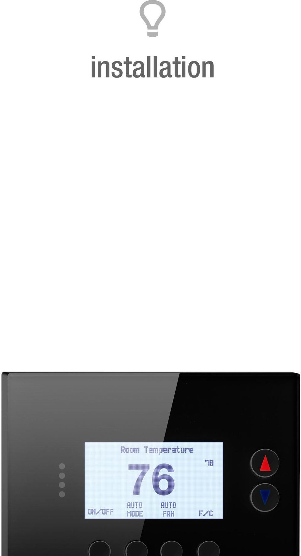
5 installation
6 Installation Page 6 HVAC System Setup Overview The thermostat requires that you setup the type and configuration of your HVAC system for proper operation. This is done in the Thermostat Info screen Setup button or the Installer Settings screen on the thermostat. The Installer Settings is a hidden screen. To access it, press the main menu button and when the main menu screen appears, press and hold the middle two buttons for 5 seconds. Thermostat Main Menu Installer Settings Screen Done Menu Selection User Settings Away Setpoints ZWave Install Thermostat Info Select Installer Settings Display Lock N Service Mode System Settings Max Heat SP 90 Done + _ Select Press and hold two middle buttons to enter the Installer Settings screen Installer Settings Before operating the system, you must configure the thermostat for the correct HVAC system type. You will need to know the following information to correctly configure the thermostat. The HVAC setup is in the Mechanical Settings menu screen. HVAC system type: What type HVAC system do you have? Standard or Heat pump For Standard systems: Fan Type: Do you have Gas heat or Electric heat? For Heat Pump systems: Change over valve (or reversing valve) type: Does your system change over with cooling operation or with heating operation? Check your existing thermostat connects to help determine this. If the original system had an orange wire connected to an O terminal, then you have a changeover with cool system. If you have a brown wire connected to the B terminal, then you have a change over with heat system.

7 Installation Page 7 Installer Settings Menu Items Display Lock Y = Display LOCKED N = Display UNLOCKED Range: Y or N Default: N Allows you to lock or unlock the thermostat buttons. When the buttons are locked, you can still access the main menu, but you will not be allowed to select any menu options. The Installer Settings hidden button operation is always operational, allowing you to return to this screen and turn Display Lock off. Service Mode Range: Y or N Test Mode Y = Test mode on. Reduces all delays to 10 seconds for quicker system testing. N = Test mode off. Normal system delays. Default: N CAUTION: in test mode all system safety delays are shorten. Do not operate the system compressor in test mode. Disconnect Y1 or Y2 outputs if using test mode on a live system. System Settings Submenu Sets the HVAC operational settings below. Mechanical Settings Submenu Sets the HVAC system type and configuration. Type Range: Gas/Elec or Heat pump Default: Gas/Elec Selects HVAC type, Gas/Electric or Heat pump Fan Type Range: Gas or Elec Default: Gas Selects the Fan type if system is Gas or Electric C/O Type Range: w/cool or w/heat Default: w/cool Selects the Heat Pump Changover Valve type 2nd Stage Heat Range: Y or N Default: N Enables the 2nd Stage Heat operation

8 Installation Page 8 Aux Heat (HP) Range: Y or N Default: Y Enables the Auxiliary Heat operation. Typically the Aux Heat will be heat-strips in a Heat Pump system Schedule Enable Range: Y or N Default: N When enabled, the local thermostats scheduler function is enabled 2nd Stage Cool Range: Y or N Default: N Enables the 2nd Stage Cool operation Recovery Enable Range: Y or N Default: N For Heat Pump Systems - Intelligent setback recovery is an automatic advance start of heating to allow the system to be at a setpoint by the scheduled time, without the use of Aux heating Delta Settings The Delta T Setting is the delta, or difference between, the setpoint and current temp for determining when a heat or cool call comes on. The delta is the number of degrees away from setpoint. H/C Delta Range: 3-15 degrees Default: 3F (1C) Sets the minimum separation between heating and cooling setpoints. Attempts to lower the cooling below the heating setpoint by this amount will PUSH the heating setpoint down to maintain this separation. Same for setting the heating setpoint above the cooling setpoint, it will PUSH the cooling setpoint up to maintain this separation. Heating Delta Stage 2 ON Range: 1-8 degrees Default: 2 Sets the delta from setpoint that stage 2 heating starts. Heating Delta Stage 3 ON Range: 1-8 degrees Default: 3 Sets the delta from setpoint that stage 3 heating starts. Heating Delta Stage 1 ON Range: 1-8 degrees Default: 1 Sets the delta from setpoint that stage 1 heating starts. Heating Delta Stage 1 OFF Range: 0-8 degrees Default: 0 Sets the delta from setpoint that stage 1 heating stops. Stage 1 turns off at setpoint + Delta Stage 1. Heating Delta Stage 2 OFF Range: 0-8 degrees Default: 0 Sets the delta from setpoint that stage 2 heating stops. Stage 2 turns off at setpoint + Delta Stage 2. Heating Delta Stage 3 OFF Range: 0-8 degrees Default: 0 Sets the delta from setpoint that stage 3 heating stops. Stage 3 turns off at setpoint + Delta Stage 3.

9 Installation Page 9 Cooling Delta Stage 1 ON Range: 1-8 degrees Default: 1 Sets the delta from setpoint that stage 1 cooling starts. Cooling Delta Stage 1 OFF Range: 0-8 degrees Default: 0 Sets the delta from setpoint that stage 1 Cooling stops. Stage 1 turns off at setpoint - Delta Stage 1 Cooling Delta Stage 2 ON Range: 1-8 degrees Default: 2 Sets the delta from setpoint that stage 2 cooling starts. Cooling Delta Stage 2 OFF Range: 0-8 degrees Default: 0 Sets the delta from setpoint that stage 2 Cooling stops. Stage 2 turns off at setpoint -Delta Stage 2. Max Heat SP Range: 40F to 109F (4C-43C) Default: 90F (32C) Sets the maximum heating setpoint value. Will not ramp or accept setpoints higher that this maximum. Min Cool SP Range: 44F to 113F (6C-45C) Default: 60F (15C) Sets the minimum cooling setpoint value. Will not ramp or accept setpoints lower than this minimum. Minimum Run Time (MRT) Range: 1-9 minutes Default: 3 Sets the minimum run time before a heating/cooling cycle can turn off. Sets heating/cooling cycle time. Prevents rapid cycling. Minimum Off Time (MOT) Range: 5-9 minutes Default: 5 Sets the minimum off time before another heating/cooling cycle can begin. Provides compressor short cycle protection. Temp Response Range: 1-6 Default: 2 Adjust the temperature sensor sensitivity. Sets how fast the sensor responds to change. Fan Cycler The fan cycler function cycles the HVAC system fan for an ON period followed by an Off period continuously. Used to provide minimum air ventilation requirements. When the Fan ON time is set to a value greater than 0, an additional Cycler FAN mode is present when pressing the FAN button. Fan ON Time Range: minutes Default: 0 (=OFF) Fan OFF Time Range: minutes Default: 10

10 Installation Page 10 Restore Defaults Range: Yes, No / Default: No Restores all settings to factory defaults. Press Yes to restore defaults. Press No to exit and not restore defaults. Relay Status Display the status (on/off) of the thermostat output relays Installer Settings Summary Setting Range Default Display Lock Y or N N Locks out front buttons Service Mode Submenu Test Mode Y or N N Reduces delays for testing System Settings Submenu Mechanical Settings Submenu Sys Type Std or HP Std Fan Type Gas or Elec Gas C/O Type w/heat or w/cool w/cool 2nd Stage Heat Y or N N Aux Heat Y or N Y 2nd Stage Cool Y or N N H/C Delta 3 15 deg 3 Heat Delta Stage 1 On Heat Delta Stage 1 Off Heat Delta Stage 2 On Heat Delta Stage 2 Off Heat Delta Stage 3 On Heat Delta Stage 3 Off Cool Delta Stage 1 On Cool Delta Stage 1 Off Cool Delta Stage 2 On Cool Delta Stage 2 Off Max Heat SP F (4-42C) 90F Min Cool SP F (6-45C) 60F Min Run Time 1-9 min 3 Min Off Time 1-9 min 5 Temp Response Fan Cycler Submenu Fan Cycler ON time min 0 0 = Fan Cycler OFF Fan Cycler Off Time min 10 Restore Defaults Yes or No No Exit = no

11 Installation Page 11 USER SETTINGS Range Default Filter Service Submenu Service Interval Disabled, hrs 300 Maint Service Submenu Maint Interval Disabled, hrs 3000 Screen Timeout (to minimized screen) 0, sec 0 0 = off, will not timeout F/C Mode F or C F Sensor Calibration Submenu Internal -7 to +7 0 Backlite/Display Submenu Backlight Timeout 0, = backlite off Backlight On Brightness 0-100% 100% Backlight Off Brightness 0-100% 0% Contrast %

12 wiring
13 Wiring Page 13 Standard Gas/Electric HVAC System Wiring Cooling 24V Fan Cooling stage 1 Cooling stage 2 Remote Sensor 2 Remote Sensor 2 Sensor shield Humidity Relay Com Optional 24R Connection for single transformer HVAC Systems RC and RH are jumpered together on thermostat board. Cut RC/RH jumper JP1 for separate heating & cooling transformers 24RC G Y1 Y2 RS2 RS2 RSC HC Thermostat Back 24C 24RH W1 W2/O RS1 RS1 RSC H1 24VAC Com 24V Heating Heating stage 1 Heating stage 2 Remote Sensor 1 Remote Sensor 1 Sensor shield Humidity Relay Default Setup: Gas/Elec Gas Heat 1 Stage Heating 1 Stage Cooling No setup required for this configuration. Shielded cable Shielded cable Remote Outside Sensor Remote Indoor Sensor Contact Closure Input Humidifier/Dehumidifier Standard HVAC System Thermostat Connection C 24VAC Common R 24VAC Return W1 Heat Stage 1 W2 Heat Stage 2 G Fan Y1 Compressor Stage 1 Y2 Compressor Stage 2 Setup To set the HVAC system type, go to the Thermostat Info screen and press Setup button. Type - Set the HVAC System Type: set to Gas/Elec Fan Type - Set the HVAC Fan Type: Set to Gas for typical gas furnance (fan is controlled by the furnance) or set to Elec for electrical heat (fan call with heat) C/O type - Not used for standard systems. Ignore this setting. 2nd Stage Heat - Enable second stage heating outputs. If you have a single stage heating system, leave this set to N. If you have a 2 stage heating system, set to Y to enable. Aux Heat (HP) - Not used for standard systems. Ignore this setting. 2nd Stage Cool - Enable second stage cooling outputs. If you have a single stage cooling system, leave this set to N. If you have a two stage cooling system, set to Y to enable.

14 Wiring Page 14 Heat Pump HVAC System Wiring Cooling 24V Fan Cooling stage 1 Cooling stage 2 Remote Sensor 2 Remote Sensor 2 Sensor shield Humidity Relay Com Thermostat Back For Heat Pump systems, connect the 24R connection to either the 24RC or 24RH 24RC G Y1 Y2 RS2 RS2 RSC HC Shielded cable Remote Outside Sensor Contact Closure Input Humidifier/Dehumidifier 24C 24RH W1 W2/O RS1 RS1 RSC H1 Heat Pump HVAC System Thermostat Connection C 24VAC Common R 24VAC Return W1 Aux Heat O G Fan 24VAC Com 24V Heating Aux Heating Change Over Valve Remote Sensor 1 Remote Sensor 1 Sensor shield Humidity Relay Shielded cable Remote Indoor Sensor Change Over Valve Y1 Compressor Stage 1 Y2 Compressor Stage 2 Note! If you get heating when you expected cooling, change the C/O type to the opposite setting. Setup To set the HVAC system type, go to the Thermostat Info screen and press Setup button. Type - Set the HVAC System Type: set to Heat Pump Fan Type - Automatically set for heat pump systems. Ignore this setting. C/O type - Change Over (reversing) Valve Type. Heat pumps change from heating to cooling by reversing operation.you must configure the thermostat s changeover valve setting to work correctly with your HVAC system. Check your system information to be sure and note the color of original thermostat wire and the terminal it was connected to. No matter what the old stat connection was (O or B), connect the wire to the thermostats W2/O terminal. The setting of the C/O Type will set the correct system operation. For change over with cool systems (Orange wire, O terminal): set C/O type to w/cool (most common and default setting). For change over with heat systems (Brown wire, B terminal): set C/O type to w/heat. 2nd Stage Heat - Enable second stage heating outputs. If you have a single stage heating system, leave this set to N. If you have a 2 stage heating system, set to Y to enable. Aux Heat (HP) - If you have auxiliary heat strips, set this to Y to enable. 2nd Stage Cool - Enable second stage cooling outputs. If you have a single stage cooling system, leave this set to N. If you have a two stage cooling system, set to Y to enable.

15 CORPORATE 16 South Maryland Ave. Port Washington, NY

16

37-7498. Professional Contractor INSTALLATION GUIDE
 37-7498 Professional Contractor INSTALLATION GUIDE Wireless Setup Connect Exit Next Exit 3 EASY STEPS Installing Sensi thermostat isn t that different than installing a non Wi-Fi thermostat. 1. Install
HEAT HEAT COOL HEAT PUMP COOL
 OWNER S MANUAL RESIDENTIAL THERMOSTAT P/N P374-1800 HEAT COOL HEAT PUMP Su AUTO 0I20: Pm 74 COOL HEAT 27 7-DAY MABLE DIGITAL THERMOSTAT 3 Configurable Outputs Accepts Optional Humidity Module: Control
INSTALLATION AND OPERATION MANUAL
 RCS MODEL ZC4 4 ZONE HVAC INSTALLATION AND OPERATION MANUAL DCN: 141-0020-02 /0/03 INTRODUCTION The 4 Zone HVAC Controller series allows up to 4 standard electronic thermostats to independently control
Sensi TM. Wi-Fi Programmable Thermostat MANUAL OPERATION. Version: March 2016 2016 Emerson Electric Co. All rights reserved.
 Sensi TM Wi-Fi Programmable Thermostat MANUAL OPERATION Version: March 2016 2016 Emerson Electric Co. All rights reserved. Contents MANUAL OPERATION GUIDE Buttons and Icons 3 Basic Functionality 4 Manual
HVAC-32A. Operation Manual. Specifications. Digital Multistage Air Conditioning Controller with inbuilt Outside Air Economy function
 Specifications Supply Voltage 240VAC @ 0.07Amps or 24VAC @ 0.380Amps Relays 240V @ 12A max (resistive) / Comp1,2,3, Aux Ht, Rv O/B) Fuses (Equipment) 15 Amps Maximum 3AG Control Range Minus 10 to 50C Control
its ELECTRIC POSITION for electric heat, or set the units fan control appropriately to ELECTRIC or another appropriate setting.
 Troubleshooting Poor Temperature Regulation This page lists problems that may affect the temperature performance of your LUX thermostat with suggested resolutions. For more detailed information please
HP 5 Microprocessor Control for Mammoth Water Source Heat Pumps
 HP 5 Microprocessor Control for Mammoth Water Source Heat Pumps Operation and Maintenance Manual Model: 71028004 Applies to: Single Circuit Water-to-Water Twin Circuit Units Without DDC Controls MAMM WHSP
Install Guide CT100. Caution. Caution ENGLISH. disconnect the power supply before beginning work.
 Install Guide CT100 PG 1 Caution top cover Your thermostat is a precise instrument, handle it with care. Turn off electricity to the system before installing or servicing thermostat or any part of the
Installation Instructions
 Installation Instructions Model TSTATG2111 Use with most systems: 2-Heat, 1-ool 1- Day Prog ram m ab l e Digital Thermostat u p t o 2 - H e a t & 1 - o o l ontrol up to 2 Heat & 1 ool Stages Backlit Display
HEAT PUMP PROGRAMMABLE THERMOSTAT
 HEAT PUMP PROGRAMMABLE THERMOSTAT SA PM 3 COOL TEMP Form 44014-01 r010408 Model 43168 Owners Manual 1 Congratulations! Heat Pump Programmable Thermostat Model 43168 THERMOSTAT CONTROLS Switches & Buttons...15
Variable Air Volume - VAV
 Mode Enable Sensor Options Variable Air Volume - VAV The temperature of this sensor will determine if the unit is in heating, cooling or vent mode during occupied operation. The following options are available:
Install Guide CT101. Caution. Caution
 Install Guide CT101 PG 1 Caution top cover Your thermostat is a precise instrument, handle it with care. Turn off electricity to the system before installing or servicing thermostat or any part of the
Overview - Danfoss Link and living software versions
 Danfoss Link CC Mk II (with minisd card) software..35.3.7.4.5 0--00 The initial Danfoss Link CC software: Supports all features from the original Devilink software. New functionality providing control
Table of Contents. 1 - Specifications...3. 2 - Installation...3. 3 - Wiring...5. 4 - User controls...7
 THERMOSTATS Table of Contents Page 1 - Specifications...3 1.1 - Product range...3 ARTTH001 (DSL-610)...3 ARTTH002 (DSL-700)...3 ARTTH003 (DSL-600)...3 1.2 - Technical data...3 1.3 - Power failures...3
Installation Guide. LR-HWLV-HVAC TouchPRO Wireless. System Types
 Installation Guide LR-HWLV-HVAC TouchPRO Wireless Touchscreen Thermostat System Types Gas, oil, or electric heat with air conditioning Warm air, hot water, high efficiency furnaces, heat pumps, steam,
NOTE: Append this Operation IB to the Install IB to make one IB-booklet. Need a divider tab between the 2 sections. Blank page remove.
 Product Name: CT101 Document Title: CT101 Operation Guide Document Type Code: IBOE Part Number: 1202-004-002 20apr12 Iris inclusion text added mtf 9apr12 bs edits mtf 14mar12 ch edits mtf 13mar12 initial
Heating and Cooling Basics Thermostat Control
 Heating and Cooling Basics Thermostat Control UNI-LINE PRODUCT KNOWLEDGE 2012 Invensys. All Rights Reserved. The names, logos, and taglines identifying the products and services of Invensys are proprietary
Mode Switch. Fan Switch Menu button Program button
 Operation 3M-30 Day Time of day Target Temperature Time Slot Touch Screen Current Room Temperature Thermostat Mode Statement of use: The 3M-30 can be used with millivolt, 24VAC, single and 2 stage conventional
Installation Guide. VisionPRO. TH8000 Series. Need Help? This manual covers the following models. System Types
 Installation Guide VisionPRO TH8000 Series Touch-screen Programmable Thermostat This manual covers the following models TH8110U: For 1 Heat/1 Cool systems TH8320U: For up to 3 Heat/2 Cool systems TH8321U:
INSTALLER S & OWNER S MANUAL
 INSTALLER S & OWNER S MANUAL HVAC INSTALLER: PLEASE LEAVE MANUAL FOR HOMEOWNER DEH 3000 DEH 3000 Part No. 4028539 Dehumidifier & Ventilation System Controller P.O. Box 8680 Madison, WI 53708 TOLL-FREE
Nest Learning Thermostat Pro installation & configuration guide
 Nest Learning Thermostat Pro installation & configuration guide Need help? Help online: http://support.nest.com/certified Nest Certified Professional support: 1-855-VIP-NEST (1-855-847-6378) Hours: 5am-9pm
Installation Instructions
 TP-PRH-A, TP-NRH-A Performance Series Edge Thermidistat Control Installation Instructions Programmable Control A07049 A07048 Non Programmable Control Designed and Assembled in the USA. NOTE: Read the entire
Install Guide 3M-50. Caution. Caution
 PG 1 Install Guide 3M-50 aution Your thermostat is a precise instrument, handle it with care. Turn off electricity to the HVA system before installing or servicing thermostat or any part of the system.
QUICK INSTALLATION GUIDE
 QUICK INSTALLATION GUIDE Read Installer Notes before removing cover from Thermostat. 1F85RF-275 Wireless Remote Kit INSTALLER NOTES IMPORTANT Do not apply power to the thermostat or wireless sensor until
ComfortLink II Installation Guide. 3 Zone Panel (optional) 4 Zone Sensor with Display (optional) 5 Zone Sensor (optional) 6 Zone Dampers (optional)
 4 Zone Sensor with Display (optional) 5 Zone Sensor (optional) 6 Zone Dampers (optional)") 18-HD64D1-3 ComfortLink II Installation Guide Other Installation Guides may be necessary, based on system configuration. A complete list of other optional components is shown below. 1 Control 2 Relay Panel
18-HD64D1-3 ComfortLink II Installation Guide Other Installation Guides may be necessary, based on system configuration. A complete list of other optional components is shown below. 1 Control 2 Relay Panel
Communicating Wall Control Installation Manual TSTAT0101SC
 Communicating Wall Control Installation Manual TSTAT0101SC U.S. Patent No. 7,243,004 U.S. Patent No. 7,775,452 616 01 1017 02 08/07/12 Safety Considerations... 7 Introduction... 8 Quick Start... 9 Set
PRODUCT PRODUCT CODE TECHNICAL INSTRUCTIONS PAGE
 Table of Contents PRODUCT PRODUCT CODE TECHNICAL INSTRUCTIONS PAGE # Electric Room Comfort Controller NEW! RDY2000 Room Comfort Controller RDY 129-905 D-3 Electric for Specialized Applications Surface
1 For All Non-Programmable Digital Thermostat
 OWNER'S MANUAL P/N P474-0100 1 For All Non-Programmable Digital Thermostat TOTALINE 68 Dual Setpoint Very easy to program Thermoglow Backlight No batteries required Auto-Changeover Locking Keypad Meets
Operation Guide 3M-22
 Operation Guide 3M-22 TEMP UP Target Temp Time Reset TEMP DOWN Control Panel Heat/Cool Mode Switch Fan Switch Battery Compartment Statement of use: The 3M-22 can be used with - millivolt, 24VAC single
T6861 Series Large LCD Digital Thermostat 110/220 VAC 2-pipe/4-pipe fan coil control
 T Series arge CD Digital Thermostat 0/0 VAC -pipe/-pipe fan coil control Data sheet Application T digital thermostats are designed for application of -speed fan and s in fan coil system. Including: -pipe
INSTALLER S SYSTEM SETUP GUIDE
 2009 Lennox Industries Inc. Dallas, Texas, USA INSTALLER S SYSTEM SETUP GUIDE icomfort Thermostat Touch Screen Programmable Communicating Thermostat CONTROLS 506052 01 11/09 Litho U.S.A. Shipping and Packing
The THERMOSTAT THE EVOLUTION OF CAPABILITIES INTO A PLATFORM FOR ENERGY MANAGEMENT
 The THERMOSTAT THE EVOLUTION OF CAPABILITIES INTO A PLATFORM FOR ENERGY MANAGEMENT Presented by: Michael Kuhlmann President Residential Control Systems Inc The Basics Thermostat Functions Measure Room
TABLE 1: Wiring Terminals. Connect to... 1C 1H 2C 2H 1H1C 2H1C 2H2C 3H2C
 Installation TURN OFF POWER TO THE SYSTEM AT THE MAIN POWER PANEL TO AVOID ELECTRICAL SHOCK. Installation should be carried out by an electrician or a qualified technician. 1.1 Find a Location for the
Integration Note. Manufacturer: OVERVIEW AND SUPPORTED FEATURES. OMNISTAT 2 (RC-1000 and RC-2000) WIRED MODELS ONLY.
 WIRED MODELS ONLY.") Manufacturer: Model Number(s): Minimum Core Module Version: Comments: HAI Document Revision Date: 4/18/2013 OMNISTAT 2 (RC-1000 and RC-2000) WIRED MODELS ONLY Firmware V. 1.03 Tested Integration Note OVERVIEW
Manufacturer: Model Number(s): Minimum Core Module Version: Comments: HAI Document Revision Date: 4/18/2013 OMNISTAT 2 (RC-1000 and RC-2000) WIRED MODELS ONLY Firmware V. 1.03 Tested Integration Note OVERVIEW
User Guide ecobee3. 2014 ecobee 250 University Ave Suite 400 Toronto Ontario M5H 3E5 Canada Toll free 1.877.932.6233 www.ecobee.
 User Guide ecobee3 2014 ecobee 250 University Ave Suite 400 Toronto Ontario M5H 3E5 Canada Toll free 1.877.932.6233 www.ecobee.com e3-ug-r001 1 Table of Contents Overview... 4 Getting Help... 4 Touch Screen...
FAQs. Conserve package. Gateway... 2 Range Extender... 3 Smart Plug... 3 Thermostat... 4 Website... 7 App and Mobile Devices... 7
 FAQs Conserve package Gateway... 2 Range Extender... 3 Smart Plug... 3 Thermostat... 4 Website... 7 App and Mobile Devices... 7 FAQs Gateway Can I have someone install my system for me? If you are concerned
AC-115 Compact Networked Single Door Controller. Installation and User Manual
 AC-115 Compact Networked Single Controller Installation and User Manual December 2007 Table of Contents Table of Contents 1. Introduction...5 1.1 Key Features... 6 1.2 Technical Specifications... 7 2.
TICS - Integrated Control Strategy TICS - Total Integrated Control Strategy Mid Range System
 TICS - Total Integrated Control Strategy Mid Range System Underfloor Heating & Cooling Control Solutions Energy efficient Heating and cooling TICS - Mid Range System Mid Range System TICS Mid Range Install
ELECTRIC POSITION for electric heat, then confirm with Fan Test below.
 Troubleshooting Poor Temperature Regulation This page lists problems that may affect the temperature performance of your LUX thermostat with suggested resolutions. For more detailed information please
SERVICE MANUAL FOR 6535 SERIES TWO TON HIGH EFFICIENCY PACKAGED HEAT PUMPS
 SERVICE MANUAL FOR 6535 SERIES TWO TON HIGH EFFICIENCY PACKAGED HEAT PUMPS TABLE OF CONTENTS 1. Warnings...2 2. Accessibility Of Appliance...3 3. Unit Dimensions And Specifications...3 4. Unit Specifications
Installation Instructions
 TP --- PAC, TP --- PHP TP --- NAC, TP --- NHP Performance Series AC / HP Thermostat Installation Instructions A07049 Programmable Control A07048 Non-Programmable Control Designed and Assembled in the U.S.A.
PSPA711a. LUXPRO PSPA711a INSTALLATION AND OPERATING INSTRUCTIONS. Mt. Laurel, New Jersey 08054, USA www.luxproproducts.com
 PSPA711a LUXPRO PSPA711a INSTALLATION AND OPERATING INSTRUCTIONS 52070 1 COMPATIBILITY...................................... 2 2 FEATURES............................................ 2 3 ELECTRICAL RATINGS................................
T5000 T000 LCD Digital Fan Coil Thermostat
 T5000 T000 LCD Digital Fan Coil Thermostat T000 LCD Digital Fan Coil Thermostat T000 LCD Digital Fan Coil Thermostats are designed to control heating, cooling, or year round air conditioning unit in Commercial,
How To Control A Thermostat
 CONTENTS Installation Instructions for Heating & Air Conditioning 1F72 5/2 Day Programmable Heat Pump Thermostat Preparations... 1 Thermostat Details... 1 Removing Old Thermostat... 1-2 Mounting and Wiring...
Programmable Thermostat MODEL 3312026.XXX With Dehumidify 3312024.XXX With Out Dehumidify
 Comfort Control Center 2 Thermostat Operating Instructions Programmable Thermostat MODEL 3312026.XXX With Dehumidify 3312024.XXX With Out Dehumidify TABLE OF CONTENTS About your new thermostat Features...2
1F82-261 Programmable Electronic Digital Heat Pump Thermostat INSTALLATION AND OPERATION INSTRUCTIONS
 FAILURE TO READ AND FOLLOW ALL INSTRUCTIONS CAREFULLY BEFORE INSTALLING OR OPERATING THIS CONTROL COULD CAUSE PERSONAL INJURY AND/OR PROPERTY DAMAGE. DESCRIPTION ELECTRICAL DATA Electrical Rating: 20 to
Thermostatic Wiring Principles by Bob Scaringe Ph.D., P.E.
 Thermostatic Wiring Principles by Bob Scaringe Ph.D., P.E. Basic Thermostat Types Many technicians have great difficulty understanding how to properly wire a thermostat or how to replace a thermostat with
USER MANUAL WARNING! CONTENTS MODEL 1 SPECIFICATIONS READ ALL INSTRUCTIONS BEFORE PROCEEDING. Non-Programmable Single Stage Heat/Cool Thermostat
 Builder MODEL 1010 Series Non-Programmable Single Stage Heat/Cool Thermostat USER MANUAL Compatible with low voltage single stage gas, oil or electric heating or cooling systems, including single stage
WHITE-RODGERS COMFORT-SET 90 SERIES
 INSTALLATI DESCRIPTI WHITE-RODGERS COMFORT-SET 90 SERIES MULTI-STAGE INSTALLATI/CFIGURATI This White-Rodgers Automatic Setback Digital Thermostat uses microcomputer technology to provide precise time and
1F82-0261 5/1/1 Day Programmable. 1F82-0261 Thermostat Thermostat Configuration Options Heat Pump. Maximum Stages Heat/Cool 2/1
 Blue 2 Heat Pump Thermostat Heat Pump Installation and Operating Instructions Save these instructions for future use! FAILURE TO READ AND FOLLOW ALL INSTRUCTIONS CAREFULLY BEFORE INSTALLING OR OPERATING
COMFORT CONTROL - 4 HEAT (GAS, OIL*, OR ELECTRIC)/3 COOL/HEAT PUMP COMMUNICATING PROGRAMMABLE 3 WIRE HOOKUP
/3 COOL/HEAT PUMP COMMUNICATING PROGRAMMABLE 3 WIRE HOOKUP") COMFORT CONTROL - 4 HEAT (GAS, OIL*, OR ELECTRIC)/3 COOL/HEAT PUMP COMMUNICATING PROGRAMMABLE 3 WIRE HOOKUP ALL phases of this installation must comply with NATIONAL, STATE, AND LOCAL CODES INSTALLER S
COMFORT CONTROL - 4 HEAT (GAS, OIL*, OR ELECTRIC)/3 COOL/HEAT PUMP COMMUNICATING PROGRAMMABLE 3 WIRE HOOKUP ALL phases of this installation must comply with NATIONAL, STATE, AND LOCAL CODES INSTALLER S
Installation Questions
 Installation Questions How do I determine what type of heat I have? There may be several ways to determine what type of heat you have. First, if you can access the unit that is responsible for creating
Water-Source Heat Pump
 Application Jauary 1999 Water-Source Heat Pump Application Economizer (Optional) BO-6,7 Discharge Air Temperature (Optional) Heating/Cooling Coil AI-6 Outdoor Air Temperature (Optional) Aux Input AI-5
Zoning Reference Guide
 Zoning Reference Guide Part No. RG-0508-001 Table of Contents Introduction 1 Braeburn Zone Systems: Comfort on Demand 1 What is a Zoning System? 2 The Braeburn Advantage 4 The Best Value in Zoning Today
Operation manual. Daikin Altherma hybrid heat pump EHYHBH05AA EHYHBH08AA EHYHBX08AA. Operation manual Daikin Altherma hybrid heat pump.
 EHYHBH05AA EHYHBH08AA EHYHBX08AA English Table of contents Table of contents 1 About this document 2 2 About the system 2 2.1 Components in a typical system layout... 2 3 Operation 3 3.1 Overview: Operation...
REGULINE 600VA / 1000VA REGULATOR USER MANUAL
 REGULINE 600VA / 1000VA REGULATOR USER MANUAL TUNÇMATİK REGULINE SERIES AUTOMATIC VOLTAGE REGULATOR Models: REGULINE 600VA / REGULINE 1000VA Principle of Operation Automatic Voltage Regulators regulate
Monitoring Network DMN
 Monitoring Network DMN User Manual Table of contents Table of contents... 2 1. Product features and capabilities... 3 2. System requirements... 5 3. Getting started with the software... 5 3-1 Installation...
SMS Alarm Messenger. Setup Software Guide. SMSPro_Setup. Revision 090210 [Version 2.2]
![SMS Alarm Messenger. Setup Software Guide. SMSPro_Setup. Revision 090210 [Version 2.2]](/thumbs/29/13662687.jpg "SMS Alarm Messenger. Setup Software Guide. SMSPro_Setup. Revision 090210 [Version 2.2]") SMS Alarm Messenger SMSPro_Setup Revision 090210 [Version 2.2] ~ 1 ~ Contents 1. How to setup SMS Alarm Messenger?... 3 2. Install the SMSPro_Setup software... 5 3. Connection Type... 6 4. Connection Port
SMS Alarm Messenger SMSPro_Setup Revision 090210 [Version 2.2] ~ 1 ~ Contents 1. How to setup SMS Alarm Messenger?... 3 2. Install the SMSPro_Setup software... 5 3. Connection Type... 6 4. Connection Port
1 4. 3 4-2 ABNORMAL OPERATION. 4-2-1 Error code Display. Specifics Error Code. Subsection Error Code. Subsection and Specifics Error code target
 4-2 ABNORMAL OPERATI 4-2-1 An is represented by 3 digit characters. The first 2 digit means the subsection, and the last 1 digit means the specifics. Ex.) Indoor unit Network communication Error Subsection
Configuring Alarms & Relays in the Enhanced Transformer Advantage
 Configuring s & Relays in the Enhanced Transformer Advantage The Transformer Advantage product family offers a variety of relay options. Some choices are made when the Advantage is specified and ordered.
COMPTROL 5000 INDEX 52. Issue 5.99 AIR CONDITIONING MICROPROCESSOR OPERATING INSTRUCTIONS. STULZ GmbH, Hamburg
 COMPTROL 5000 INDEX 52 Issue 5.99 AIR CONDITIONING MICROPROCESSOR STULZ GmbH, Hamburg OPERATING INSTRUCTIONS Contents Page INTRODUCTION... 4 NOTES ON SAFETY... 4 PAGE CODE... 4 DESCRIPTION OF THE CONTROLLER...
ETC TWO STAGE ELECTRONIC TEMPERATURE CONTROL
 RANCO INSTALLATION INSTRUCTIONS ETC TWO STAGE ELECTRONIC TEMPERATURE CONTROL Relay Electrical Ratings PRODUCT DESCRIPTION The Ranco ETC is a microprocessor-based family of electronic temperature controls,
Installing the Tracer ZN517 Unitary Controller Ordering number: 4950 0496, 4950 0596
 Installing the Tracer ZN517 Unitary Controller Ordering number: 4950 0496, 4950 0596 Product overview The Tracer ZN517 controller is a field-installed, application-specific controller that provides directdigital
Using the STC-1000+ firmware
 Using the STC-1000+ firmware Project home at Github Features Both Fahrenheit and Celsius versions Up to 6 profiles with up to 10 setpoints. Each setpoint can be held for 1 999 hours (i.e. up to ~41 days).
HCS-3300/3302/3304 USB Remote Programmable Laboratory Grade Switching Mode Power Supply
 1. INTRODUCTION HCS-3300/3302/3304 USB Remote Programmable Laboratory Grade Switching Mode Power Supply User Manual This family of efficient, upgraded SMPS with small form factor, auto cross over CV CC,
Temperature Control from Lutron
 TouchPRO Wireless thermostat seetemp wall control in White Temperature Control from Lutron Home Control+ app Use Lutron s Home Control+ app to manage your home s temperature while at home or while you
YOUR THERMOSTAT REPLACES Assemble tools required as shown below. HAND OR POWER DRILL WITH 3/16 INCH DRILL BIT, IF NEEDED
 1F85-275 Heating & Air Conditioning 5-1-1 Programmable/Non-programmable, Auto Changeover, Multi-Stage/Heat Pump Thermostat INSTALLATION INSTRUCTIONS Operator tor: Save these instructions for future use!
INSTALLATION MANUAL RS4220 RS5220 RS6220 RS4110 RS5110 RS6110
 RS4110 RS5110 RS4220 RS5220 RS6220 INSTAATIN MANUA 352-00060-001 Rev. A RS4000 Series RS5000 Series RS6000 Series Thank you for purchasing a Robertshaw thermostat. This manual will describe how to install
LGAC-KNX PROGRAMMING MANUAL. Integrations V1.0 TECHNICAL SUPPORT. Tel (+34) 985 113 339 [email protected]
 985 113 339 tecnico@ingeniumsl.com") Integrations LGAC-KNX V1.0 PROGRAMMING MANUAL Parque Tecnológico de Asturias, Parcela 50, 33428 Llanera Asturias - Spain Tel (+34) 985 118 859 Fax (+34) 984 283 560 [email protected] www.ingeniumsl.com
Integrations LGAC-KNX V1.0 PROGRAMMING MANUAL Parque Tecnológico de Asturias, Parcela 50, 33428 Llanera Asturias - Spain Tel (+34) 985 118 859 Fax (+34) 984 283 560 [email protected] www.ingeniumsl.com
Blue Easy Reader Thermostat 1F95EZ-0671. Homeowner s Guide
 Blue Easy Reader Thermostat 1F95EZ-0671 Homeowner s Guide Message to Homeowners Congratulations on choosing the Emerson Blue Easy Reader Thermostat. Blue Easy Reader is designed to be the easiest thermostat
C-Bus Application Messages & Behaviour Chapter 25 Air Conditioning
 C-Bus Application Messages & Behaviour Chapter 25 Air Conditioning Document Number: CBUS-APP/25 Comments on this document should be addressed to: Engineering Manager Clipsal Integrated Systems PO Box 103
TC-9102 Series Surface Mount Temperature Controllers
 TC-9102 Series Surface Mount Temperature Controllers General Description & Applications The TC-9102 Series Temperature Controller offers a versatile solution for a wide variety of applications that may
OWNERS MANUAL. Status Monitor. for Windows 95, 98, ME, NT 4, 2000 & XP. SIGNALCRAFTERS TECH, INC. www.signalcrafters.com
 OWNERS MANUAL Status Monitor for Windows 95, 98, ME, NT 4, 2000 & XP SIGNALCRAFTERS TECH, INC. www.signalcrafters.com 57 Eagle Rock Avenue, East Hanover, NJ 07936 Tel: 973-781-0880 or 800-523-5815 Fax:
AUTOMATIC TRANSFER SWITCH CONTROL UNIT OPERATOR S MANUAL
 ATS-220 AUTOMATIC TRANSFER SWITCH CONTROL UNIT OPERATOR S MANUAL For Use in 208 to 240 Volts Single and 3 Phase ATS Systems With 110Volt AC or DC Control Motors and selenoids 4501 NW 27 ave Miami FL 33142
4 Alarm and info. Alarm. Yes Warning. No Information No Reset alarms > No Current list > Alarm log list > Delete alarm log > No
 6. 6.1 and info (Menu 4) NB are shown in the event of unit faults or irregular operation Check the Current list (Menu 4) for alarm messages and refer to the list of alarms given at the end of these instructions.
RZAHUC program version 1.1 Regulation for Reznor Air Handling Units
 INSTALLATION INSTRUCTIONS OPTION 1xxx 1104_1000_EN Comfort Regulation (Carel pco) Detailed instructions RZAHUC program version 1.1 Regulation for Reznor Air Handling Units INDEX 1. Introduction... 4 1.1.
1-877-654-9394. UP400 Programmable Thermostat Installation Instructions & User Guide. For Installation Help. White-Rodgers.com
 UP400 Programmable Thermostat Installation Instructions & User Guide For Installation Help 1-877-654-9394 White-Rodgers.com 2011 Printed in China White-Rodgers 8100 West Florissant Avenue St. Louis, MO
INSTALLATION GUIDE. www.security.soundstream.com FCC ID NOTICE
 AL.1 AUTO SECURITY SYSTEM INSTALLATION GUIDE www.security.soundstream.com FCC ID NOTICE This device complies with Part 15 of the FCC rules. Operation is subject to the following conditions: 1. This device
Features and Benefits
 Refrigeration 2 eatures and Benefits Based on IR32 Parameters Real Time lock ( RT ) Model Specific (defrost based on real time 7 day 24 hour) HAP (Hazard Analysis and ritical ontrol Point) Alarm Available
Liebert Deluxe System/3
 Precision Cooling For Business-Critical Continuity Liebert Deluxe System/3 Operation and Maintenance Manual 50 and 60 Hz, 6-30 Ton DX Systems (DH/DE/VH/VE); 12-60 Ton CW Systems (FH/UH) TABLE OF CONTENTS
General Information. Do programmable thermostats really save energy?
 General Information Do programmable thermostats really save energy? Yes, programmable thermostats can save energy which in turn saves you money on your utility bill. The US Department of Energy states
Controller Automation, Model II+
 Controller Automation Page 2 of 2 Automation with the RADAK II+ power controller II+ I/O Points: Inputs 5 Programmable Digital inputs 2 Dedicated digital inputs (Channel select and External SCR control
MicroTech III Unit Controller for Water Source Heat Pump Units
 Operation & Maintenance Data OM 931-1 Group: WSHP Part Number: 910100893 Date: April 2009 MicroTech III Unit Controller for Water Source Heat Pump Units 2009 McQuay International Table of Contents Introduction...
Flush-mounted room thermostats
 s 3 076 RDF300, RDF300.02, RDF340 RDF400.01 RDF600 RDF600 Flush-mounted room thermostats for 2-pipe, 2-pipe with el. heater and 4-pipe fan coil units for use with compressors in DX type equipment RDF300
GETTING STARTED WITH THE MIPOWER MANAGEMENT SYSTEM
 GETTING STARTED WITH THE MIPOWER MANAGEMENT SYSTEM This Quick Start guide will help you start using the MiPower Management System provided by Grayson Collin Electric Cooperative. You should create your
WIRING HARNESS FOR AS635P4. BLUE PLUG RED, BLUE, BLACK, WHITE - Plug in dual stage sensor harness
 WIRING HARNESS FOR AS635P4 ANTENNA NOT USED 5 PIN WHITE PLUG 2 PIN WHITE PLUG GREEN - PARKING BRAKE INPUT (-) BLUE - NOT USED 3 PIN BLUE PLUG RED, BLUE, BLACK, WHITE - Plug in dual stage sensor harness
Operation manual. Daikin Altherma low temperature monobloc EBLQ05CAV3 EBLQ07CAV3 EDLQ05CAV3 EDLQ07CAV3
 EBLQ05CAV3 EBLQ07CAV3 EDLQ05CAV3 EDLQ07CAV3 English Table of Contents Table of Contents 1 About this document 2 2 About the system 2 2.1 Components in a typical system layout... 2 3 Operation 3 3.1 Overview:
Safety & Installation Instructions
 Home omfort ontrol Model 8910 READ AND SAVE THESE INSTRUTIS Safety & Installation Instructions Table of contents Installation Thermostat installation location recommendations.. 2 Thermostat mounting...
Automatic start of a generator
 Automatic start of a generator General description This application note will help you to set your Xtender for an automatic start of a generator as per different parameters such as the output power, the
LS1024B / LS2024B/ LS3024B. Solar Charge Controller USER MANUAL
 EPSOLAR LS1024B / LS2024B/ LS3024B Solar Charge Controller USER MANUAL Thank you very much for selecting our product! This manual offers important information and suggestions with respect to installation,
Technical Information
 Date of last update: Oct-11 Ref: D7.8.4/1011/E Application Engineering Europe CORESENSE DIAGNOSTICS FOR STREAM REFRIGERATION COMPRESSORS CoreSense Diagnostics for Stream Refrigeration Compressors... 1
Inwall Room Temperature Unit
 Inwall Room Temperature Unit TM11B01KNX TM11B11KNX TM11B21KNX Product Handbook Product: Inwall Room Temperature Unit Order Code: TM11B01KNX TM11B11KNX TM11B21KNX Application Program ETS: TM11B_1KNX Inwall
NL708 (XWA11V) Walk-In Temp / Door /Alarm / Light Module
 Walk-In Temp / Door /Alarm / Light Module") NL708 (XWA11V) Walk-In Temp / Door /Alarm / Light Module 1. General Description 1 2. General Warnings 1 3. Interface 2 4. Temp Alarms Setting 3 5. Programming 3 6. Light Management 4 7. Installation and
NL708 (XWA11V) Walk-In Temp / Door /Alarm / Light Module 1. General Description 1 2. General Warnings 1 3. Interface 2 4. Temp Alarms Setting 3 5. Programming 3 6. Light Management 4 7. Installation and
User Manual. ATX12V / EPS12V Power Supply TG-I460R (460W+460W) TG-I550R (550W+550W) Switching Power Supply User Manual
 TG-I550R (550W+550W) Switching Power Supply User Manual") ATX12V / EPS12V Power Supply TG-I460R (460W+460W) TG-I550R (550W+550W) User Manual Table of Contents 1 Introduction 2 General specification 3 Installation 4 Pin assignment & function of connectors 5 Drawing
ATX12V / EPS12V Power Supply TG-I460R (460W+460W) TG-I550R (550W+550W) User Manual Table of Contents 1 Introduction 2 General specification 3 Installation 4 Pin assignment & function of connectors 5 Drawing
R&D Electronics 8440 N. Waukegan Rd., Morton Grove, IL 60053 -- (847) 583-9080 -- Issue 12/08/06 om_207f.doc --
 583-9080 -- Issue 12/08/06 om_207f.doc --") R&D Electronics 8440 N. Waukegan Rd., Morton Grove, IL 60053 (847) 5839080 Issue 12/08/06 om_207f.doc MODEL AH 207 Heat Call MICRO PROCESSOR SYSTEM Temperature Averaging OWNERS MANUAL Model AH207, 207M
R&D Electronics 8440 N. Waukegan Rd., Morton Grove, IL 60053 (847) 5839080 Issue 12/08/06 om_207f.doc MODEL AH 207 Heat Call MICRO PROCESSOR SYSTEM Temperature Averaging OWNERS MANUAL Model AH207, 207M
INSTALLATION INSTRUCTIONS MC95HAE-1 MASTER CONTROLLER
 INSTALLATION INSTRUCTIONS MC95HAE-1 MASTER CONTROLLER Bard Manufacturing Company, Inc. Bryan, Ohio 43506 Since 1914...Moving ahead just as planned. Manual : 2100-360B Supersedes: 2100-360A File: Volume
MAKING MODERN LIVING POSSIBLE. living connect. Installation and User Guide. Danfoss heating
 MAKING MORN LIVING POSSIBLE Danfoss heating living connect Installation and User Guide Contents 1.0 System overview... 3 2.0 Overview of display and control buttons... 3 3.0 Installation - step by step...
HCE80/HCC80/HCE80R/HCC80R
 HCE80/HCC80/HCE80R/HCC80R UNDERFLOOR HEATING-ZONEING CONTROLLERS PRODUCT DATA FEATURES Easy and fast installation because the new wiring design Pluggable terminals for fast wiring connection because clamp
Functional Profile: Heat Pump with Temperature Control
 Heat Pump with Temperature Control: 8051 LONMARK Functional Profile: Heat Pump with Temperature Control LONMARK Functional Profile: Heat Pump with Temperature Control 1 8051-10 1996, LONMARK Interoperability
Digi-Motor Installation Guide
 Digi-Motor Installation Guide Installation Video...located at marsdelivers.com Digi-Motor Installation Guide Digi-Motor For technical assistance with your Azure Digi-Motor, call the MARS technical support