The GeoMedia Fusion Validate Geometry command provides the GUI for detecting geometric anomalies on a single feature.
|
|
|
- Monica Thompson
- 8 years ago
- Views:
Transcription
1 The GeoMedia Fusion Validate Geometry command provides the GUI for detecting geometric anomalies on a single feature. Below is a discussion of the Standard Advanced Validate Geometry types. Empty Geometry refers to features that have an empty geometry component. (e.g. A composite or collection without any components or a geometry that is returned as an empty variant). Unknown Geometry Type refers to those features whose geometry type does not correspond to a type recognized by GeoMedia. More specifically, when the top-level blob header does not conform to any of the geometry CLSID defined in GDO. Invalid Geometry refers to those features whose geometry type does not match the geometry s delineation (e.g. an area whose subtype is not gdbareal or gdbanyspatial) or whose geometry specification is invalid for GeoMedia. Invalid Geometric Component refers to those features whose geometry is syntactically correct (i.e. passed the check as specified by the Invalid Geometry anomaly), but whose specification does not define a valid geometric component. Included in the definition of invalid geometries are the following: Invalid Arc the radius, start point, and end point are not valid. Invalid Boundary - the boundaries exterior or interior components are not polygons. Discontinuous Composite - the composite does not form a connected path. Uncontained Holes refers to area features with inner boundaries (holes) that are not contained (totally or partially) within the outer boundary. Unclosed Areas refers to area features whose boundary does not close. In other words, the first and last point of the boundary do not have the same coordinate values. 22

2 The process identifies the original feature geometry. Specifically, the first and last points of the boundary are identified. The anomaly geometry is a Geometry Collection containing two points corresponding to the first and last point of the area. Overlapping Holes refers to area features whose inner boundaries (holes) overlap one another. Zero-Length Lines refers to linear features whose coordinates all occupy the same xy location. The process identifies the original feature geometry. The anomaly geometry is a polyline containing the points in the original geometry. Zero-Coverage Areas refers to areas features that have no area (i.e. the vertices are all collinear). The process identifies the original feature geometry. The anomaly geometry is a polyline containing the points in the original geometry. Loop in Area refers to area features that contain a loop in either its outer or inner boundaries. No measurement is required as any loop is considered an anomaly. Kickback refers to linear or area features where the geometry doubles back on itself. 23

3 The line above is defined by a sequence of 10 vertices (A-B-C-D-C-D-E-F-G-H). The sequence D-C-D defines the kickback. A kickback is corrected by removing the vertices that create the kickback. In the above example, the second set of vertices at C and D are removed. The line is defined by the sequence of 8 vertices (A-B-C-D-E-F-G-H). This is a simple case of a Kickback. The process identifies the original feature geometry. Specifically, the vertex or set of two vertices that defined the kickback. The anomaly geometry is either a single point for a duplicate point (corresponds to the location of the duplicate point) or a Geometry Collection containing two vertices that represent the kickback. Below is a discussion of the Advanced Validate Geometry Specialized Anomaly types Kink (or Spike) refers to linear or area features where there is a sudden divergence of the vertices that define the geometry. A measurement is required to distinguish between kinks and what are considered normal characteristics of the feature. In the above line, the vertex sequence A-B-C defines a sudden divergence of the line. This divergence can be a kink. Loop in Line refers to linear features whose geometry creates a loop whose area is greater than some specified tolerance. 24
 or a Geometry Collection containing two vertices that represent the kickback.")
4 Unlike Loop in Area, not all loops in line features are anomalies. Only those loops whose size is less than some specified parameter are considered anomalies. In the above definition, small loops are considered anomalies, while larger ones are considered a normal characteristic. Since the loop is considered an abnormal characteristic, the vertices placed to create the loop can be considered as invalid. Removing these vertices and thus removing the loop can be considered the proper way to correct this anomaly. Short Vector refers to line or area features with two sequential vertices less than some userspecified tolerance from one another. In the above example, the line has two sequential vertices (A and B) that are less than some specified tolerance from one another. This defines the Short Vector Anomaly. Correcting the Short Vector anomaly requires removal of one of the vertices. Although subtle differences could result depending on which vertex is removed it appears that those differences can be ignored. In the above example, resolution is achieved by deleting point A. Fragmented Geometry refers to a feature whose geometry is a collection of distinct geometries. The collection could be any combination of area, lines and/or points. The geometries belonging to the collection do not need to be discontiguous for it to be considered a fragmented geometry anomaly. An automated resolution is available for those feature recordsets with an auto-number key field. If the recordset has a key field or fields other than auto-number, no automatic resolution is available. New records are created for each separate geometry in the collection. Optionally, the original record can be kept and used as one of the new features created. The attribute values for the new records are copied from the original record and a geometry is created that corresponds with one of the distinct elements in the collection. If the original record is kept, its geometry is modified to correspond to one of the geometry components. Duplicate Feature refers to two features whose attributes match and whose geometries are either identical or have similar size, shape, and location within some specified tolerance. The 25

5 example below illustrates two line and two area features whose geometries do not match, but which may still be considered duplicates. Although the two line and area geometries above do not match exactly, they have similar size, shape, and location, and may be considered duplicates. Determination of whether two features are duplicates can be made by creating zones around the features and analyzing the spatial relationship of the two zones to one another. The picture below shows the lines above with buffer zones around each of them. For points to be considered duplicates, one point only need be within the specified buffer distance of another for it to be considered a duplicate (i.e. no calculation of the overlap between the zones is required). The certainty value for a point being a duplicate of another is either 0 (not within buffer distance) or 100 (within buffer distance). Due to the complexity of analyzing Geometry Collections, they will be considered for exact duplicates only at this time. Geometry Collections will not be processed for near duplicates. The attribute check is performed optionally. Either all attributes must match for a feature to be considered a duplicate, or no attributes are checked, in which case the geometry only is processed. When attributes are checked, all fields with the exception of key fields and geometry fields must have the exact same values. 26

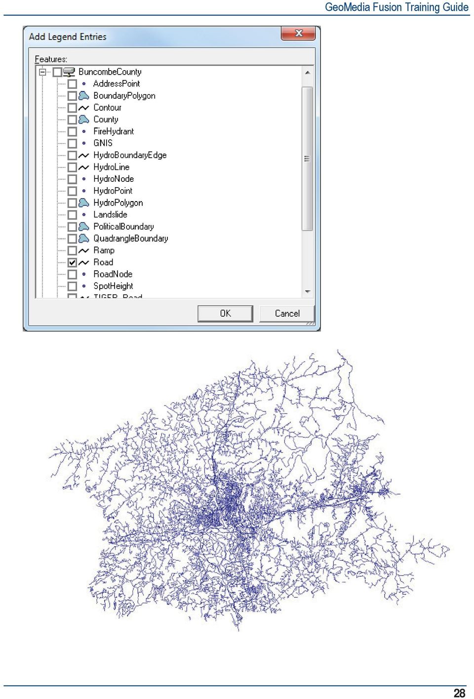
6 Void Area refers to a bounded region that does not belong to any area feature. Void Area would be an anomaly for map data that is required to be continuous coverage. In the example above, two area features are coincident in such a way as to create a bounded region that does not belong to either area feature. This bounded region is an example of a Void Area Anomaly. The unbounded regions of the data under consideration that do not belong to an area are not detected as a Void Area. The data would have to be modified so that these regions become bounded before they would be identified as a Void Area Anomaly. The results are output as a query and can be displayed in a map window, data window, and/or queue. The command uses the AdvancedValidateGeometryPipe and the DuplicateFeaturePipe (through the AdvancedValidateGeometryProps Control) to determine the anomalies on the selected feature classes. Any changes to the geometries of the features for which anomalies are detected will automatically update in any open map or data windows and any dynamic queues. Superfluous Geometry refers to those instances where the geometry of a feature contains a component which is not needed to portray the feature. Included in Superfluous Geometry are zero-length arcs and composites or collections with only one component. 1. Select Geomedia Professional and open the Geoworkspace of C:\Training/Buncombe/BuncombeCounty.gws. 2. Select Legend > Add Legend Entries and select the BuncombeCounty connection and the feature class of Road. 27

7 28
8 3. Select Toolbox > Geometric Validation > Validate Geometry. 4. Select the Input tab and select the BuncombeCounty connection feature class of Road. 29

9 5. Select the Anomalies tab and review the Standard and Specialized entries. 30

10 6. Check all of the Standard and Specialized entries. 7. Select the Output tab and keep the Output anomalies to queue checked to Queue of Anomalies and Output anomalies as query checked. 31

11 8. Select the OK button on the Advanced Validate Geometry dialog. 9. The Queued Edit Map Window, the Queued Edit Data Window, and the Queued Edit control will activate when the processing concludes. 10. Scroll through the Queued Edit list of Queue of Anomalies and review the detected Geometric anomalies. 32

12 11. Notice that Kinks, Duplicate Feature, Fragmented Geometry, and Null Geometry anomalies have been detected. 33

13 12. Select the Toolbox > Validate Geometry > Anomalies tab and check the Specialized Kink, Duplicate Feature, Fragmented Geometry, and Null Geometry options. 13. Select the Input tab and select the BuncombeCounty connection Road feature class. 34

14 14. Select the Anomalies tab and set the Anomaly properties: Auto correct fields to Yes for the selected anomalies. This will automatically resolve the Geometric anomalies. 15. Select the OK button on the Advanced Validate Geometry dialog. 35

15 16. The Queued Edit Map Window, Queued Edit Data Window, and Queue of Anomalies are now redisplayed with 0 anomalies. 17. Close the Queued Edit Map Window and exit the Queued Edit command. GeoMedia Professional only allows for connectivity to be validated between two feature classes (a source and a target). Connectivity of the source feature is compared with the target feature. Fusion allows for connectivity between multiple feature classes to be checked. The connectivity of each feature in each class is checked between all other features in the specified classes. Fusion also provides an advanced feature selection mode where, depending on the anomaly type, connectivity is checked between two groups of feature classes. GeoMedia Pro checks for connectivity in a pair-wise fashion; one feature in the source feature class against one feature in the target feature class. This can result in over reporting due to the fact that other features in the target class are not checked simultaneously against the feature. More Fusion anomaly types are detected. An output to a queue option is available. GeoMedia Pro detects anomalies between features by a pair-wise analysis of the geometry. Only two geometries are compared at a time without regard to any other related geometries. 36

16 Undershoots In the example below, feature A is connected to feature B, which then crosses feature C. A pair-wise analysis of the features as done in GM Professional leads to the conclusion that feature A undershoots feature C. Fusion does not see this as an undershoot. It looks at the entire connected topological network and determines that no undershoot exists. Fusion looks at the geometry of all the features involved, not just a pair-wise analysis. This can cause the results returned by the products to vary. For those anomaly types that can be corrected, the user can specify to correct them as they are encountered, in which case they are not output to the queue. Note that correction of the undershoot as done in GeoMedia Professional could lead to features A and B no longer remaining coincident at their endpoints. Since feature B is not considered, feature A is extended to feature C to correct the undershoot, causing the two features to no longer be connected at their endpoints. Geomedia Pro looks for undershoots by taking an endpoint of a line and comparing with other features. If a line can be drawn normal to a segment on another feature and if the distance is less than the specified 37

17 tolerance, an undershoot is reported. Fusion measures the distance from the endpoint to the intersection of another segment along the original trend of the line. This difference can be outlined below. Feature A is being compared against feature B for an undershoot. Geomedia Pro looks for the perpendicular distance between the endpoint of feature A and a segment on feature B. Because this perpendicular line does not intersect feature B, no undershoot is detected or reported. Fusion measures the distance along the original trend of the line (shown in green). If the distance from the endpoint to this intersection is less than the tolerance, an undershoot is reported. In another example above, the endpoint of line A is within the specified distance (undershoot tolerance) of line C. Therefore, the relationship of line A to line C represents an undershoot. Line B is not within the specified tolerance of line C; therefore it is not an undershoot. The undershoot distance is calculated by projecting the line (Line A or Line B) along its original direction until it meets the undershot line (Line C). A perpendicular projection is not made. Undershoots can be corrected by extending the line to meet the undershot line. (In this case, extending A to meet C). However not all situations are this straightforward, which could require the user to review and edit the features in order to resolve them. The two features and the location are identified where the undershoot occurs. The endpoint of the undershooting feature along with location on the undershot feature where projection would occur. Overshoots Given the same example above, the effect of the pair-wise comparison can be seen for overshoots as well. A pair-wise analysis of the features as done in GM Pro leads to the conclusion that feature B overshoots feature C 38

18 Fusion does not see this as an overshoot. It looks at the entire connected network and makes the decision that no undershoot exists. Correction of the overshoot of feature B to feature C would lead to a similar undesirable result where feature B is terminated at the intersection to feature C and becomes disconnected from feature A. Correcting undershoots and overshoots could lead to the following results for this case. In another example (below), line A extends past line C a distance less than the specified distance (undershoot tolerance). Therefore, the relationship of line A to line C represents an overshoot. Line B extends past line C a distance greater than this tolerance, and therefore does not represent an overshoot. Overshoot Tolerance Line C Line A Line B Overshoots can be corrected by deleting the part of the line that extends past the overshot line. (In this case, deleting the part of line A that extends past C). However, not all situations are this straightforward, which could require the user to review and edit the features in order to resolve. An overshoot could also be a case of Unbroken Intersecting Geometry. If this is the case, the overshoot should be corrected, which will in effect correct Unbroken Intersecting Geometry. An overshoot that is 39
, line A extends past line C a distance less than the specified distance (undershoot tolerance). Therefore, the relationship of line A to line C represents an overshoot.")
19 also an Unbroken Intersecting Geometry should be identified solely as an Overshoot and corrected as such. An overshoot could and will in all likelihood be also Non-coincident. However correcting the overshoot will correct the Non-coincident Intersecting Geometry. Node Mismatch The effect of the pair-wise comparison for node mismatches does not cause Geomedia Professional to report anomalies that do not exist as for overshoots or undershoots. It does, however, cause anomalies to be over-reported. In the above example, the endpoints of 2 lines are all within a specified node mismatch tolerance of one another. Because of the pair-wise comparison done in GeoMedia Professional, this one anomaly will be reported twice (AB, BA). Fusion would report this anomaly one time. Only being able to select two feature classes and only comparing one feature class to another leads to different results for GeoMedia Professional than for Fusion. In the above example, node B belongs to feature class 1, and is within the tolerance of both node A and node C of feature class 2. Node A and Node C are also within the node mismatch tolerance. GeoMedia Professional will report four node mismatches (AB, BA, BC, CB). It does not report AC as a mismatch, as they are from the same feature class. Fusion processes the feature classes together, comparing FC1 to FC2 and FC1. This results in a single anomaly being reported with all three nodes as the mismatch. This allows for the mismatching 3 nodes to be resolved as a group. Since they are not a single anomaly in Geomedia Professional and resolved as such, the effects of correcting this situation in Pro can lead to varying results. For example, if the mismatch AB is corrected first, the mismatch BC may no longer exist. This is because B has been moved, and may no longer be in tolerance to C. This could result in the following result if auto-corrected. 40

20 Node C may no longer be within the node mismatch tolerance, and thus no longer be a mismatch with the adjusted nodes A and B. Because Fusion sees this as one anomaly with three nodes, it is corrected by averaging the coordinates of all three points so that the three lines meet at a common point. Common Point Here is another example of endpoints of lines, intersections, and/or point features that are within a specified distance of one another. 41

21 In the above example, three lines terminate within a specified distance of one another. Pairwise, the distance from each node to the other nodes is less than the specified tolerance value. Therefore, this situation is a node mismatch. Node mismatches can be corrected in a couple of different ways. First, by averaging the coordinate values of all the nodes in question and moving the offending nodes to that location. Average of A,B and C If one feature takes precedence over the others, then the endpoints of the other features can be moved to the endpoint of higher precedence. This may require the operator to make a choice. In our example, nodes B and C are moved to A, which is the node that is of higher priority. A An automatic option is available to correct the simpler cases. Only cases where the anomalous features are the endpoints of line or point nodes are corrected. If one of the nodes is defined by an intersection, no automatic resolution is possible. Also, no secondary mismatches can exist. In other words, for a group of features that mismatch, each feature in that group must meet the mismatch criteria with every other feature in that group and must not mismatch with features outside the group. When this occurs, the node mismatch can be corrected by averaging the coordinates of all nodes and moving the nodes to this new location. 42
22 Unbroken Intersecting Geometry The effect of pair-wise comparison causes no differences between GeoMedia Professional and Fusion for the Unbroken intersecting geometry, other than how the anomalies are reported. For example, when two lines cross and both are unbroken, Pro will report this as two anomalies in the data window. Unbroken Intersecting Geometry refers to a linear feature that crosses over another linear feature or area boundary instead of being broken into separate features at the intersection point. Unbroken Intersecting Geometry can be corrected by splitting the features that cross over into multiple features. In the above example, Line 1 and Line 2 are both split into two lines. The intersection point serves as the point where the two lines are split. Non-coincident Intersecting Geometry The effect of pair-wise comparison for non-coincident intersecting geometry is the same as that for the Unbroken intersecting geometry. When two lines cross and both are non-coincident Pro will report this as two anomalies in the data window. Fusion will report this as a single queue item identifying that both features need to have a vertex added at the intersection. No real differences other than how the anomalies are reported to the user. Non-coincident Intersecting Geometry refers to the situation where a line or areas cross over one another without corresponding vertices at the intersection points. 43
23 Non-coincident Intersecting Geometry can be corrected by inserting vertices on the features at the location of the intersection. Non-coincident intersecting geometry anomalies not only occur at the point of intersection between two features, but also occur when features share a linear segment. If points on the shared segment don t belong to all features that share that segment, these points are considered anomalies. Shared linear geometry 44
24 Tolerance Nearly Coincident Correcting Nearly Coincident Geometry will require the user to review and make a decision as to whether the features will need to be separated, brought together to share geometry, or left alone. 1. Select Toolbox > Geometric Validation > Validate Connectivity. 2. Select Road as the input feature class. 45
25 3. Select the Anomalies tab and check all of the Standard Anomaly types as shown. 4. Check the Standard Anomaly types and change the Overshoot, Undershoot, and Node Mismatch Tolerance values to
26 *HR0HGLD )XVLRQ 7UDLQLQJ *XLGH 5. Click the OK button on the Advanced Validate Connectivity dialog to begin processing. 6. Note that 470 anomalies are detected and queued in the AnomaliesQueue queue, and the anomalies are also loaded in the activated Queued Edit Map Window and Queued Edit Data Window. 7. Select Legend > Add Legend Entries and add the Road feature class to the Queued Edit Map Window. The Road feature class will now be displayed with the anomaly in the Map Window. 47
27 8. The symbology of Road feature class and the AnomalyGeometry of Anamolies Queue item may have to be changed so the two entries are legible in the Queued Edit Map Window. 9. Scroll through the AnomaliesQueue queue and review the various connectivity anomalies, such as Overshoots, Undershoots, and Unbroken Intersections. 10. The Queued Edit Options icon of Queuing Options > General > Show Description box may have to be selected do the Anomaly description can be reviewed. 48
28 11. Select Toolbox > Geometric Validation > Validate Connectivity, select the Road feature class, select the Anomalies tab, and change all of the 5 Standard Anomaly type Auto correct entries to Yes. 49
29 12. Click OK on the Advanced Validate Connectivity dialog to begin processing the Road features with the Auto correct entry set to Yes. 13. Note that 5 unbroken intersections and 4 node mismatches remain. This is because Road cul-desacs connected to an endpoint are considered to be an unbroken intersection. The node mismatches can t be resolved because there are 3 or more nodes detected and Validate Connectivity doesn t know which items to resolve. 50
30 Sliver refer to a two-dimensional closed space that exists between line and/or area boundaries. A sliver is considered an anomaly when its dimension does not exceed some measurement. Slivers as defined are two-dimensional closed regions formed by the intersection of lines or area geometries. The following measurements can be made on a closed region to distinguish slivers (an anomaly) from what one might consider a normal characteristic Area, Perimeter, Length and Width. 51
31 The area of the closed region is shown in shown below.. The perimeter is the length of the boundary of the region as The width (or average width) can be calculated by dividing the area by the length. The length can be estimated by calculating a longest path centerline for the area. In the picture below, the dashed line represents the centerline. The measurements area, length, perimeter, width, and area/perimeter^2 can be used individually or in combination to determine a sliver. Examples: A combination of the Area and Perimeter. If the area is less than a certain threshold and the perimeter is greater than another threshold, a region may be considered a sliver. A combination of the Length and Width. If the length is greater than a threshold and the width is less than a threshold, a region may be considered a sliver. There are different methods and parameters that can be used to measure faces to determine if they are a sliver. These methods and possible ways to correct slivers are outlined in Appendix. Shared Edge refers to the situation where a line or area boundary shares an edge (coincident linear geometry) with another line or area boundary. An anomaly exists when the edge is less than some specified length (tolerance). 52
32 Shared Edge E1 In the above example, Line A and Area C share edge E1. The length of E1 is less than the specified tolerance; therefore, it is considered an anomaly. Line B and Area C share edge E2 whose length is greater than the specified tolerance; therefore, it is not an anomaly. Correcting shared edge anomalies would require operator review to consider whether the features should be moved apart, their geometry edited, or left alone. Dead End refers to a line feature that does not terminate (both start and end) on another feature. If the length of this line feature is less than some specified tolerance, then it is considered an anomaly. 53
33 Dead end anomalies may be corrected by simply removing the feature. Otherwise, operator review may be required. 1. Select Toolbox > Geometric Validation > Validate Connectivity. 2. Select the Input tab and select the BuncombeCounty connection PoliticalBoundary feature class as the input feature for processing. 3. Select the Anomalies tab and check all of the Specialized anomaly options. Specify a value of 5000 as the Area in the Anomaly properties field for both slivers and gaps. 54
34 4. Select the OK button on the Advanced Validate Connectivity dialog. 5. Notice that 8 slivers have been detected and loaded into the Queued Edit AnomaliesQueue3 queue. The Queued Edit Map Window and Queued Edit are now activated and the anomalies are shown in the Queued Edit Map Window. 6. Add the feature class of PoliticalBoundary to the Queued Edit Map Window legend. The symbology of Political Boundary and AnomalyGeometry of Anomalies Queue2 may have to changed so the features are legible in the Queued Edit Map Window. 7. Scroll through the AnomaliesQueue2 anomaly entries and review the PoliticalBoundary feature slivers. There is currently not an option to automatically resolve sliver anomalies so it will be necessary to use GeoMedia Professional editing tools (Merge, etc.) to manually fix the slivers. 55
35 8. Close the Queued Edit Map Window and exit the Queued Edit command. Attribute Validation provides a set of commands to assist you in creating attribute validation rules that can be executed against a warehouse connection that contains feature classes and attributes. The result is a validation queue of feature classes and attributes that failed during the validation of the rules, and/or a validation log file. 56
Topology. Shapefile versus Coverage Views
 Topology Defined as the the science and mathematics of relationships used to validate the geometry of vector entities, and for operations such as network tracing and tests of polygon adjacency Longley
Working with Geodatabase Topology
 Developed and Presented by Juniper GIS 1/38 Course Objectives Understanding how Geodatabase Topology works Geodatabase Rules Creating Geodatabase Topology Editing with Geodatabase Topology Geometric Networks
Tutorial: 2D Pipe Junction Using Hexa Meshing
 Tutorial: 2D Pipe Junction Using Hexa Meshing Introduction In this tutorial, you will generate a mesh for a two-dimensional pipe junction, composed of two inlets and one outlet. After generating an initial
Convert 2D to 3D in AutoPOL Bend Simulator
 Convert 2D to 3D in AutoPOL Bend Simulator This document gives an introduction of how to convert 2D DXF/DWG files into 3D models in AutoPOL Bend simulator. The AutoPOL 3D concept A 3D model with correct
Canterbury Maps Quick Start - Drawing and Printing Tools
 Canterbury Maps Canterbury Maps Quick Start - Drawing and Printing Tools Quick Start Guide Standard GIS Viewer 2 Canterbury Maps Quick Start - Drawing and Printing Tools Introduction This document will
Editing Common Polygon Boundary in ArcGIS Desktop 9.x
 Editing Common Polygon Boundary in ArcGIS Desktop 9.x Article ID : 100018 Software : ArcGIS ArcView 9.3, ArcGIS ArcEditor 9.3, ArcGIS ArcInfo 9.3 (or higher versions) Platform : Windows XP, Windows Vista
Using Map Topology Editing Tools
 Using Map Topology Editing Tools What You Will Need in ArcView This tutorial, written by Colin Childs, is a companion to the article ArcGIS Topology for ArcView Users, also by Colin Childs, that appeared
University of Arkansas Libraries ArcGIS Desktop Tutorial. Section 5: Analyzing Spatial Data. Buffering Features:
 : Analyzing Spatial Data Buffering Features: A buffer operation is one of the most common spatial analysis tools. A buffer is a map feature that represents a uniform distance around a feature. When creating
A HYBRID APPROACH FOR AUTOMATED AREA AGGREGATION
 A HYBRID APPROACH FOR AUTOMATED AREA AGGREGATION Zeshen Wang ESRI 380 NewYork Street Redlands CA 92373 Zwang@esri.com ABSTRACT Automated area aggregation, which is widely needed for mapping both natural
10.0-2. Finite Element Modeling
 What s New in FEMAP FEMAP 10.0 and 10.0.1 include enhancements and new features in: User Interface on page 3 Meshing on page 23 Mesh Associativity on page 33 Properties on page 33 Functions on page 35
Data Validation Online References
 Data Validation Online References Submitted To: Program Manager GeoConnections Victoria, BC, Canada Submitted By: Jody Garnett Brent Owens Refractions Research Inc. Suite 400, 1207 Douglas Street Victoria,
Chapter 1. Creating Sketches in. the Sketch Mode-I. Evaluation chapter. Logon to www.cadcim.com for more details. Learning Objectives
 Chapter 1 Creating Sketches in Learning Objectives the Sketch Mode-I After completing this chapter you will be able to: Use various tools to create a geometry. Dimension a sketch. Apply constraints to
7 Enclosed Areas. When you have completed this chapter, you will be able to:
 7 Enclosed Areas Our designs so far have consisted entirely of open linework, except for a brief introduction to Fill Attributes on page 3-15. Closed linework may delineate an Area, such as a section of
SOLIDWORKS: SKETCH RELATIONS
 Sketch Feature: The shape or topology of the initial sketch or model is important, but exact geometry and dimensions of the initial sketched shapes are NOT. It recommended to work in the following order:
Pro/ENGINEER Wildfire 5.0 Introduction to Surface Modeling
 Introduction Several advanced surface types are available as listed below. Variable Section Sweep Boundary Blend Section to Surfaces Blend Surface to Surface Blend A surface is created by sweeping a single
Introduction to CATIA V5
 Introduction to CATIA V5 Release 16 (A Hands-On Tutorial Approach) Kirstie Plantenberg University of Detroit Mercy SDC PUBLICATIONS Schroff Development Corporation www.schroff.com www.schroff-europe.com
SpaceClaim Introduction Training Session. A SpaceClaim Support Document
 SpaceClaim Introduction Training Session A SpaceClaim Support Document In this class we will walk through the basic tools used to create and modify models in SpaceClaim. Introduction We will focus on:
Data Validation and Quality Assurance with FME
 Technology Brief Data Validation and Quality Assurance with FME First, Some Background Mark Stoakes, head of the Professional Services department at Safe Software, recently gave a presentation on FME and
Web Editing Tutorial. Copyright 1995-2010 Esri All rights reserved.
 Copyright 1995-2010 Esri All rights reserved. Table of Contents Tutorial: Creating a Web editing application........................ 3 Copyright 1995-2010 Esri. All rights reserved. 2 Tutorial: Creating
Petrel TIPS&TRICKS from SCM
 Petrel TIPS&TRICKS from SCM Knowledge Worth Sharing Create Fault Polygons and Map This is the first in a series of TIPS&TRICKS focused on the geophysical and seismic aspects of Petrel. Petrel combines
TELECOM FIBER EDITING TOOLS REFERENCE GUIDE Version 1.2
 TELECOM FIBER EDITING TOOLS REFERENCE GUIDE Version 1.2 Prepared by: Esri 380 New York Street Redlands, California 92373-8100 Phone: (909) 793-2853 Table of Contents 1. Overview and Getting Started...
SolidWorks Implementation Guides. Sketching Concepts
 SolidWorks Implementation Guides Sketching Concepts Sketching in SolidWorks is the basis for creating features. Features are the basis for creating parts, which can be put together into assemblies. Sketch
Composite Surfaces Tutorial
 Composite Surfaces Tutorial 4-1 Composite Surfaces Tutorial This tutorial will use the same model as the Materials & Loading Tutorial (with some modifications), to demonstrate how to perform a circular
GIS Data in ArcGIS. Pay Attention to Data!!!
 GIS Data in ArcGIS Pay Attention to Data!!! 1 GIS Data Models Vector Points, lines, polygons, multi-part, multi-patch Composite & secondary features Regions, dynamic segmentation (routes) Raster Grids,
Raster to Vector Conversion for Overlay Analysis
 Raster to Vector Conversion for Overlay Analysis In some cases, it may be necessary to perform vector-based analyses on a raster data set, or vice versa. The types of analyses that can be performed on
GIS Spatial Data Standards
 GIS Spatial Data Standards Manatee County, FL GIS Section, Information Services Department TABLE OF CONTENTS I. Introduction 2 A. Purpose 2 B. Reference 2 II. Spatial Reference Information 2 A. Projection:
Part Number: PMT1080-ENG Rev. 1
 2010 Dassault Systèmes, All Rights Reserved DraftSight and the DraftSight logos are trademarks of Dassault Systèmes or its subsidiaries in the US and/or other countries. Other brand or product names are
Getting Started With DraftSight A Guide For AEC Users
 Getting Started With DraftSight A Guide For AEC Users DraftSight.com Facebook.com/DraftSight Welcome to DraftSight a valuable tool for any AEC professional! DraftSight is more than a free, professional-grade
1. Launch ArcCatalog, then navigate to the following location using the directory tree on the left side of the screen:
 Vector Data Analysis I: Buffering Today we will use ArcMap and ArcToolbox to manipulate vector-based geographic data. The results of these simple analyses will allow us to visualize complex spatial relationships.
Understand the Sketcher workbench of CATIA V5.
 Chapter 1 Drawing Sketches in Learning Objectives the Sketcher Workbench-I After completing this chapter you will be able to: Understand the Sketcher workbench of CATIA V5. Start a new file in the Part
Creating a File Geodatabase
 Creating a File Geodatabase Updated by Thomas Stieve January 06, 2012 This exercise demonstrates how to create a file geodatabase in ArcGIS 10; how to import existing data into the geodatabase, and how
What s New V 11. Preferences: Parameters: Layout/ Modifications: Reverse mouse scroll wheel zoom direction
 What s New V 11 Preferences: Reverse mouse scroll wheel zoom direction Assign mouse scroll wheel Middle Button as Fine tune Pricing Method (Manufacturing/Design) Display- Display Long Name Parameters:
SE OF THE PROGRAM...5
 MyHatch User guide PREFACE... 2 GOAL OF THE SOFTWARE... 2 DEFINITION OF HATCHES IN AUTOCAD... 2 MYHATCH PROGRAM... 2 DEFINITION OF HATCH PATTERNS... 3 USE OF THE PROGRAM... 5 INSTALLATION... 5 TOOLBAR
Lab 3. GIS Data Entry and Editing.
 Lab 3. GIS Data Entry and Editing. The goal: To learn about the vector (arc/node) and raster data types entry and editing. Objective: Create vector and raster datasets and visualize them. Software for
MA 323 Geometric Modelling Course Notes: Day 02 Model Construction Problem
 MA 323 Geometric Modelling Course Notes: Day 02 Model Construction Problem David L. Finn November 30th, 2004 In the next few days, we will introduce some of the basic problems in geometric modelling, and
Spatial Database Support
 Page 1 of 11 Spatial Database Support Global Mapper can import vector data from and export vector data to the following spatial databases: Esri ArcSDE Geodatabase Esri File Geodatabase Esri Personal Geodatabases
Basic AutoSketch Manual
 Basic AutoSketch Manual Instruction for students Skf-Manual.doc of 3 Contents BASIC AUTOSKETCH MANUAL... INSTRUCTION FOR STUDENTS... BASIC AUTOSKETCH INSTRUCTION... 3 SCREEN LAYOUT... 3 MENU BAR... 3 FILE
3D-GIS in the Cloud USER MANUAL. August, 2014
 3D-GIS in the Cloud USER MANUAL August, 2014 3D GIS in the Cloud User Manual August, 2014 Table of Contents 1. Quick Reference: Navigating and Exploring in the 3D GIS in the Cloud... 2 1.1 Using the Mouse...
Event Manager. LANDesk Service Desk
 Event Manager LANDesk Service Desk LANDESK SERVICE DESK EVENT MANAGER GUIDE This document contains information that is the proprietary and confidential property of LANDesk Software, Inc. and/or its affiliated
10. THERM DRAWING TIPS
 10. THERM DRAWING TIPS 10.1. Drawing Tips The THERM User's Manual describes in detail how to draw cross-sections in THERM. This section of the NFRC Simualation Training Manual presents some additional
Intellect Platform - The Workflow Engine Basic HelpDesk Troubleticket System - A102
 Intellect Platform - The Workflow Engine Basic HelpDesk Troubleticket System - A102 Interneer, Inc. Updated on 2/22/2012 Created by Erika Keresztyen Fahey 2 Workflow - A102 - Basic HelpDesk Ticketing System
Spatial Adjustment Tools: The Tutorial
 Spatial Adjustment Tools: The Tutorial By Peter Kasianchuk, ESRI Educational Services In this exercise, you will perform some spatial adjustment and data management operations data to be used in analysis
4 Manipulating Elements
 4 Manipulating Elements In the context of this course, Manipulation of elements means moving, copying, rotating, scaling and some other similar operations. We will find that manipulations are always a
Software: AutoCAD Civil 3D 2014, NRCS C3D 2014 template, ESRI ArcMap. Notation:Button to Press Displayed Text Icon Action {Text to Enter} Menu Item
 Overview: Use the following processes for exchanging georeferenced data between AutoCAD Civil 3D 2014 and ArcMap. The work must be based in any real world coordinate system. (This example uses NAD 83 UTM
Introduction to Autodesk Inventor for F1 in Schools
 Introduction to Autodesk Inventor for F1 in Schools F1 in Schools Race Car In this course you will be introduced to Autodesk Inventor, which is the centerpiece of Autodesk s digital prototyping strategy
Pro/ENGINEER Wildfire 4.0 Basic Design
 Introduction Datum features are non-solid features used during the construction of other features. The most common datum features include planes, axes, coordinate systems, and curves. Datum features do
Tutorial. IMPORTING AND EXPORTING AutoCAD FILES (DWG)
") In addition to Canvas numerous import and export capabilities, you can also import AutoCAD 2007 files into Canvas 11, edit them, and export to PDF format. Objectives After this exercise you will be able
In addition to Canvas numerous import and export capabilities, you can also import AutoCAD 2007 files into Canvas 11, edit them, and export to PDF format. Objectives After this exercise you will be able
FDOT Roadway Design and 3D Modeling
 State of Florida Department of Transportation FDOT Roadway Design and 3D Modeling CE-11-0138, CE-11-0139, and CE-11-0140 User Training Manual October 30, 2014 ENGINEERING / CADD SYSTEMS OFFICE TALLAHASSEE,
TABLE OF CONTENTS. INTRODUCTION... 5 Advance Concrete... 5 Where to find information?... 6 INSTALLATION... 7 STARTING ADVANCE CONCRETE...
 Starting Guide TABLE OF CONTENTS INTRODUCTION... 5 Advance Concrete... 5 Where to find information?... 6 INSTALLATION... 7 STARTING ADVANCE CONCRETE... 7 ADVANCE CONCRETE USER INTERFACE... 7 Other important
Computational Geometry. Lecture 1: Introduction and Convex Hulls
 Lecture 1: Introduction and convex hulls 1 Geometry: points, lines,... Plane (two-dimensional), R 2 Space (three-dimensional), R 3 Space (higher-dimensional), R d A point in the plane, 3-dimensional space,
Making Visio Diagrams Come Alive with Data
 Making Visio Diagrams Come Alive with Data An Information Commons Workshop Making Visio Diagrams Come Alive with Data Page Workshop Why Add Data to A Diagram? Here are comparisons of a flow chart with
Geodatabase Tutorial. Copyright 1995-2010 Esri All rights reserved.
 Copyright 1995-2010 Esri All rights reserved. Table of Contents A quick tour of the Building a geodatabase tutorial..................... 3 Exercise 1: Organizing your data in the Catalog......................
Introduction to Autodesk Inventor for F1 in Schools
 F1 in Schools race car Introduction to Autodesk Inventor for F1 in Schools In this course you will be introduced to Autodesk Inventor, which is the centerpiece of Autodesk s Digital Prototyping strategy
Etch Drawing Preparation
 Etch Drawing Preparation Introduction Most etching companies prefer you to supply the drawing for your design in the form of a computer file. While some will still accept drawn or printed artwork, it is
Introduction to ANSYS ICEM CFD
 Workshop 8.2 3D Pipe Junction 14.5 Release Introduction to ANSYS ICEM CFD 2012 ANSYS, Inc. April 1, 2013 1 Release 14.5 3D Pipe Junction 3D Pipe Junction This is a simple 4-way pipe intersection with two
HOLES 5.1. INTRODUCTION
 HOLES 5.1. INTRODUCTION One of the major open problems in the field of art gallery theorems is to establish a theorem for polygons with holes. A polygon with holes is a polygon P enclosing several other
TOWARDS AN AUTOMATED HEALING OF 3D URBAN MODELS
 TOWARDS AN AUTOMATED HEALING OF 3D URBAN MODELS J. Bogdahn a, V. Coors b a University of Strathclyde, Dept. of Electronic and Electrical Engineering, 16 Richmond Street, Glasgow G1 1XQ UK - jurgen.bogdahn@strath.ac.uk
IES <Virtual Environment> Tutorial. ModelIT (Version 6.0)
") IES Tutorial ModelIT (Version 6.0) 1 Introduction: ModelIT Tutorial This document shows you how to use ModelIT, IES s 3D building geometry modelling tool. The tutorial is intended
IES Tutorial ModelIT (Version 6.0) 1 Introduction: ModelIT Tutorial This document shows you how to use ModelIT, IES s 3D building geometry modelling tool. The tutorial is intended
Basic 2D Design Be sure you have the latest information!
 Basic 2D Design mastercam x getting started tutorials Basic 2D Design December 2011 Be sure you have the latest information! Information might have been changed or added since this document was published.
Constrained Tetrahedral Mesh Generation of Human Organs on Segmented Volume *
 Constrained Tetrahedral Mesh Generation of Human Organs on Segmented Volume * Xiaosong Yang 1, Pheng Ann Heng 2, Zesheng Tang 3 1 Department of Computer Science and Technology, Tsinghua University, Beijing
Creating a 2D Geometry Model
 Creating a 2D Geometry Model This section describes how to build a 2D cross section of a heat sink and introduces 2D geometry operations in COMSOL. At this time, you do not model the physics that describe
Utilizing Microsoft Access Forms and Reports
 Utilizing Microsoft Access Forms and Reports The 2014 SAIR Conference Workshop #3 October 4 th, 2014 Presented by: Nathan Pitts (Sr. Research Analyst The University of North Alabama) Molly Vaughn (Associate
Conjectures. Chapter 2. Chapter 3
 Conjectures Chapter 2 C-1 Linear Pair Conjecture If two angles form a linear pair, then the measures of the angles add up to 180. (Lesson 2.5) C-2 Vertical Angles Conjecture If two angles are vertical
Crystal Reports Payroll Exercise
 Crystal Reports Payroll Exercise Objective This document provides step-by-step instructions on how to build a basic report on Crystal Reports XI on the MUNIS System supported by MAISD. The exercise will
Raising the Roof Creating Roofs in Revit David Cohn
 David Cohn AB322-1 Roofs are one of the most complex architectural elements to model, but with Revit you can create just about any type of roof. This class will explore the best methods for creating various
Introduction to AutoCAD lar 543 spring 2008
 Introduction to AutoCAD lar 543 spring 2008 for landscape architects Makie Suzuki, Chihiro Shinohara in this session we cover: - introduction - basic operation - basic drawing tools - basic editing In
HowTo Rhino & ICEM. 1) New file setup: choose Millimeter (automatically converts to Meters if imported to ICEM)
 New file setup: choose Millimeter (automatically converts to Meters if imported to ICEM)") HowTo Rhino & ICEM Simple 2D model 1) New file setup: choose Millimeter (automatically converts to Meters if imported to ICEM) 2) Set units: File Properties Units: Model units: should already be Millimeters
HowTo Rhino & ICEM Simple 2D model 1) New file setup: choose Millimeter (automatically converts to Meters if imported to ICEM) 2) Set units: File Properties Units: Model units: should already be Millimeters
STL GENERATION INTRODUCTION TO STL. Written by Greta D Angelo
 STL GENERATION Written by Greta D Angelo In this section: An introduction on.stl files How to make good.stl files How to make.stl on different softwares (Solidworks, PTC Creo, Rhinoceros 5, Autodesk Inventor)
Introduction to the TI-Nspire CX
 Introduction to the TI-Nspire CX Activity Overview: In this activity, you will become familiar with the layout of the TI-Nspire CX. Step 1: Locate the Touchpad. The Touchpad is used to navigate the cursor
Geometry: Unit 1 Vocabulary TERM DEFINITION GEOMETRIC FIGURE. Cannot be defined by using other figures.
 Geometry: Unit 1 Vocabulary 1.1 Undefined terms Cannot be defined by using other figures. Point A specific location. It has no dimension and is represented by a dot. Line Plane A connected straight path.
Vector storage and access; algorithms in GIS. This is lecture 6
 Vector storage and access; algorithms in GIS This is lecture 6 Vector data storage and access Vectors are built from points, line and areas. (x,y) Surface: (x,y,z) Vector data access Access to vector
Roof Tutorial. Chapter 3:
 Chapter 3: Roof Tutorial The majority of Roof Tutorial describes some common roof styles that can be created using settings in the Wall Specification dialog and can be completed independent of the other
7 Raster-to-Vector Conversion
 7 Raster-to-Vector Conversion Preview In this lesson, you will learn how to: Set up the Vectorize for Advanced Conversion Use Themes in a Digitizing or Conversion Project Use the Vectorize Place Element
Triangulation by Ear Clipping
 Triangulation by Ear Clipping David Eberly Geometric Tools, LLC http://www.geometrictools.com/ Copyright c 1998-2016. All Rights Reserved. Created: November 18, 2002 Last Modified: August 16, 2015 Contents
Excel -- Creating Charts
 Excel -- Creating Charts The saying goes, A picture is worth a thousand words, and so true. Professional looking charts give visual enhancement to your statistics, fiscal reports or presentation. Excel
Using Ad-Hoc Reporting
 Using Ad-Hoc Reporting The purpose of this guide is to explain how the Ad-hoc reporting function can be used to produce Management Information from client and product data held in the Key. The guide will
LYON COUNTY GEOMOOSE 2 HELP DOCUMENT
 LYON COUNTY GEOMOOSE 2 HELP DOCUMENT TABLE OF CONTENTS Lyon County Geomoose 2 Help Document... 1 Introduction... 3 Quick Reference Chart... 4 The Interface... 4 The Table of Contents... 5 Quick Reference
ModelBuilder - Creating Tools Tutorial
 ModelBuilder - Creating Tools Tutorial Copyright 1995-2010 Esri All rights reserved. Table of Contents Tutorial: Creating tools with ModelBuilder......................... 3 Copyright 1995-2010 Esri. All
Importing and Opening an Alignment
 Chapter 6 Alignment Files An alignment defines the route of a road, utility line, water way, etc., and is typically comprised of both horizontal and vertical elements. Also, an alignment may include cross-sectional
ArcGIS. Tips and Shortcuts. for Desktop
 ArcGIS Tips and Shortcuts for Desktop Map Navigation Refresh and redraw the display. F5 Suspend the map s drawing. F9 Zoom in and out. Center map. Roll the mouse wheel backward and forward. Hold down Ctrl
MGL Avionics. MapMaker 2. User guide
 MGL Avionics MapMaker 2 User guide General The MGL Avionics MapMaker application is used to convert digital map images into the raster map format suitable for MGL EFIS systems. Note: MapMaker2 produces
Setting Up Global Navigator Alerts
 Setting Up Global Navigator Alerts The Alerts feature allows the Global Navigator Administrator to set up warning levels to indicate to the supervisor or manager split and/or agent conditions that may
Algolab Photo Vector
 Algolab Photo Vector Introduction: What Customers use Photo Vector for? Photo Vector (PV) is a handy tool for designers to create, cleanup, make fast corrections, edit designs with or without further conversion
E-mail Listeners. E-mail Formats. Free Form. Formatted
 E-mail Listeners 6 E-mail Formats You use the E-mail Listeners application to receive and process Service Requests and other types of tickets through e-mail in the form of e-mail messages. Using E- mail
CHAPTER 8, GEOMETRY. 4. A circular cylinder has a circumference of 33 in. Use 22 as the approximate value of π and find the radius of this cylinder.
 TEST A CHAPTER 8, GEOMETRY 1. A rectangular plot of ground is to be enclosed with 180 yd of fencing. If the plot is twice as long as it is wide, what are its dimensions? 2. A 4 cm by 6 cm rectangle has
CATIA for Design and Engineering. Version 5 Releases 14 & 15. David S. Kelley. Central Michigan University SDC
 CATIA for Design and Engineering ersion 5 Releases 4 & 5 David S. Kelley Central Michigan University SDC PUBLICATIONS Schroff Development Corporation www.schroff.com www.schroff-europe.com TUTORIAL Extruded
Using an Access Database
 A Few Terms Using an Access Database These words are used often in Access so you will want to become familiar with them before using the program and this tutorial. A database is a collection of related
To draw a line. To create a construction line by specifying two points
 Drawing Lines, Polygons and Rectangles The line is the basic object in AutoCAD. You can create a variety of lines: single lines, multiple line segments with and without arcs, multiple parallel lines, and
2010 Document Template Administration. User Guide. Document Template Administration
 User Guide Document Template Administration Page 1 Document Template Administration and Related Features: Features and Related Topics: 1 Document Template Administration:...3 2 Creating a New E-Mail Document
CATIA Drafting TABLE OF CONTENTS
 TABLE OF CONTENTS Introduction...1 Drafting...2 Drawing Screen...3 Pull-down Menus...4 File...4 Edit...5 View...6 Insert...7 Tools...8 Drafting Workbench...9 Views and Sheets...9 Dimensions and Annotations...10
Use this translator to save ArchiCAD layouts/views in DXF/DWG format if you plan to continue
 Tip Sheet ArchiCAD 11 Mark Horrocks Graphisoft New Zealand May 2007 DWG Translator In Architectural practice you often send and receive content from co-working Structural, Mechanical or Electrical Engineers.
Creating and Manipulating Spatial Weights
 Creating and Manipulating Spatial Weights Spatial weights are essential for the computation of spatial autocorrelation statistics. In GeoDa, they are also used to implement Spatial Rate smoothing. Weights
39 Symmetry of Plane Figures
 39 Symmetry of Plane Figures In this section, we are interested in the symmetric properties of plane figures. By a symmetry of a plane figure we mean a motion of the plane that moves the figure so that
Chapter 3.1 Angles. Geometry. Objectives: Define what an angle is. Define the parts of an angle.
 Chapter 3.1 Angles Define what an angle is. Define the parts of an angle. Recall our definition for a ray. A ray is a line segment with a definite starting point and extends into infinity in only one direction.
Creating Smart Models From Scan Data
 Rapidform Tech Tip Creating Smart Models From Scan Data Related Product Version Rapidform XOR3 Goal To create a smart model from scan data. A smart model is a parametric model that uses parameters intelligently
Configuration Manager
 After you have installed Unified Intelligent Contact Management (Unified ICM) and have it running, use the to view and update the configuration information in the Unified ICM database. The configuration
11 Printing Designs. When you have completed this chapter, you will be able to:
 11 Printing Designs Creating printed documents is the end we have worked towards from the beginning of this course. We have already been introduced to it very briefly with Printing - A First Look on page
ACCESS 2007. Importing and Exporting Data Files. Information Technology. MS Access 2007 Users Guide. IT Training & Development (818) 677-1700
 677-1700") Information Technology MS Access 2007 Users Guide ACCESS 2007 Importing and Exporting Data Files IT Training & Development (818) 677-1700 training@csun.edu TABLE OF CONTENTS Introduction... 1 Import Excel
Information Technology MS Access 2007 Users Guide ACCESS 2007 Importing and Exporting Data Files IT Training & Development (818) 677-1700 training@csun.edu TABLE OF CONTENTS Introduction... 1 Import Excel
Persistent Data Structures
 6.854 Advanced Algorithms Lecture 2: September 9, 2005 Scribes: Sommer Gentry, Eddie Kohler Lecturer: David Karger Persistent Data Structures 2.1 Introduction and motivation So far, we ve seen only ephemeral